
 Submit a Paper
 Propose a Special lssue
 Open Access
ARTICLE
Numerical Simulation of Turbulent Heat Transfer in Concentric Annular Pipes
1 School of Energy and Power Engineering, University of Shanghai for Science and Technology, Shanghai, 200093, China
2 School of Energy and Power Engineering, Northeast Electric Power University, Jilin, 132012, China
* Corresponding Author: Mo Yang. Email:
(This article belongs to the Special Issue: Advances in Heat and Mass Transfer: Integrating Numerical Methods with Artificial Intelligence, Machine Learning, and Data-Driven Approaches)
Frontiers in Heat and Mass Transfer 2025, 23(4), 1151-1163. https://doi.org/10.32604/fhmt.2025.067925
Received 16 May 2025; Accepted 14 July 2025; Issue published 29 August 2025
 View Full Text
 Download PDF
Abstract
In concentric annular pipes, the difference in curvature between the inner and outer wall surfaces creates significant variations in the heat transfer characteristics of the two surfaces. The simplifications of the Dittus-Boelter equation for circular pipes make it unsuitable for the complex flow induced by the geometry and heat transfer coupling effects in annular pipes. This prevents it from accurately predicting the turbulent heat transfer in concentric annular pipes. This paper used realizable κ–ε and low Reynolds number models to conduct numerical simulations of turbulent convective heat transfer in concentric annular pipes and circular pipes. The results indicated that the local heat transfer coefficient and Nusselt number of the inner wall surface of the annular pipe were both higher than those of the outer wall surface. The Darcy resistance coefficient decreased upon increasing the Reynolds number and increased with the inner diameter-to-outer diameter ratio. When using the equivalent diameter as the characteristic scale, the turbulent heat transfer correlation obtained from circular pipes produced significant errors when used to approximate the turbulent convective heat transfer in concentric annular pipes. This error was greater for the inner wall surface, especially when the inner and outer diameters were relatively small, as the Nusselt number error on the inner wall surface reached 60.62%. The error of the Nusselt number on the outer wall surface reached 19.51%.Keywords
Concentric annular pipes are used in heat exchange equipment, fluid machinery, nuclear power devices, and reactor core channels [1,2]. Accurately predicting the flow and heat transfer within these pipes is important for designing and optimizing heat exchange equipment. Previous research on turbulent convective heat transfer in pipelines has focused on circular pipes and has produced many widely used empirical correlations, such as the Dittus-Boelter (D&B) equation [3], the McAdams equation [4], the Wiegand equation [5], and Gnielinski equation [6,7]. For non-circular pipes in engineering applications, the equivalent diameter is often used as the characteristic length, and approximate calculations are conducted using turbulence heat transfer correlations for circular pipes [8,9]. It is unclear how much error this approach produces, or if this is sufficient to meet the requirements of engineering applications.
A review of the literature showed that using the equivalent diameter and correlation from experiments with circular pipes to calculate turbulent flow and heat transfer in different pipelines produces non-negligible errors. Sun [10] investigated the shortcomings of using the hydraulic diameter as the equivalent diameter and indicated that employing the equivalent diameter as the characteristic length produced significant errors in the drag coefficient and Nusselt number. Wang et al. [11] investigated the convective heat transfer and flow resistance characteristics in elliptical pipes and showed that using the equivalent diameter method to calculate the heat transfer coefficient inside elliptical pipes produced significant errors. Qiao [12] conducted numerical simulations of turbulent flow and heat transfer in rectangular pipes and also found that for rectangular pipes, the use of this approximation produced an error of up to 29.5%. Kong et al. [13] studied turbulent heat transfer in high-temperature and high-pressure gas pipelines. Their results indicated that using the Dittus-Boelter equation to calculate the heat transfer coefficient of a pipeline-type high-temperature and high-pressure gas electric heating system may lead to significant errors. The coefficient was substantially lower than the actual operating data and also lower than the results obtained from simulations. Wang et al. [14] conducted simulations on the turbulent flow and heat transfer of variable-property air in different regular polygonal pipes and circular pipes. The results showed that calculating heat transfer in non-circular pipes using the equivalent diameter and correlations from circular pipe experiments led to significant errors. For regular polygonal pipes, this error reached 27.5%. Yang et al. [15] conducted numerical simulations of turbulent convective heat transfer in circular pipes and longitudinal multi-tube bundles. They used classic empirical correlations from turbulent heat transfer experiments in circular pipes to calculate the convective heat transfer coefficients for longitudinal tube bundles. They showed that this approach yielded results that deviated significantly from those of the numerical simulations, with discrepancies reaching as high as 142.5%. Yang et al. [16] conducted a numerical simulation of turbulent convective heat transfer in an elliptical pipe. Their results showed that the relative error between the simulated Nusselt number and the value calculated using the equivalent diameter and the D&B formula reached 28.4%.
The Dittus-Boelter equation is a classic correlation for turbulent heat transfer and is based on two assumptions: axisymmetric flow in a circular pipe and that the boundary layer develops independently on a single wall surface [3,17]. In a concentric annular pipe, the boundary layers of the inner and outer wall surfaces interfere with each other, especially in narrow gaps. The different curvatures of the inner and outer walls create deviations in the velocity and temperature distribution from the fully-developed turbulence within a circular pipe. Curvature can also either suppress or enhance the turbulence intensity depending on the direction of curvature and alter the turbulence vortex structure. These factors create deviations in the Nusselt number from the values predicted by the Dittus-Boelter equation.
Due to the different curvatures of the inner and outer wall surfaces of concentric annular pipes, the centrifugal forces are different. Centrifugal forces cause shifts in the fluid flow, creating variations in the boundary layer thickness, velocity gradient, turbulence intensity, and entrance length of the inner and outer wall surfaces. For example, multi-tube coaxial heat exchangers [18–20], porous tube heat exchangers [21,22], and large tube heat exchangers [23–26] show significant differences in the heat transfer characteristics of their inner and outer wall surfaces. These differences are produced by the complex fluid flow and heat transfer and differences in thermal exchange properties of different fluids, porous medium materials, or arrangements. Considering the inner and outer walls separately enables the more accurate design of cooling/heating systems, avoiding local overheating due to insufficient heat exchange or thermal stress concentration caused by excessive heat exchange.
For concentric annular pipes, taking the equivalent diameter as the characteristic scale and using the turbulent heat transfer formula for circular pipes to approximate the calculation produces non-negligible errors. To achieve stable operation and efficient heat exchange of heat exchange equipment, it is more appropriate to separately consider the inner and outer wall surfaces. However, no research has directly addressed the convective heat transfer of turbulent flow within concentric annular pipes while separately considering the inner and outer wall surfaces. Both the Dittus-Boelter equation and the Gnielinski equation produce the same Nusselt number for both the inner and outer wall surfaces of concentric annular pipes.
This article employs numerical simulations to solve the Reynolds-averaged Navier-Stokes (N-S) equations using realizable κ–ε and low-Reynolds number models to simulate turbulent convective heat transfer in concentric annular pipes. This paper investigates the differences in heat transfer characteristics between the inner and outer surfaces of concentric annular pipes, as well as errors associated with using equivalent diameter and turbulent heat transfer correlations for circular pipes. The results provide a basis for further optimizing the thermal management of the concentric annular pipes.
2 Physical Models and Numerical Methods
Fig. 1 shows that the fluid flows perpendicularly to the cross-section of the pipe. When the fluid flows from a large space into the pipe and exchanges heat with the pipe wall, both the flow boundary layer and the thermal boundary layer start at zero, gradually thicken, and ultimately converge at the center symmetry plane of the pipe. The merging of the velocity boundary layer and thermal boundary layer indicates that the flow and heat transfer inside the pipeline have fully developed. From this point on, the heat transfer coefficient of the local surface remains constant. The area between the entrance section and the fully developed section is called the entrance section. When the flow develops to a certain extent, intense disturbances and the evolution of fluid micro-clusters cause the influence of the entrance section to gradually weaken. To eliminate the influence of the entrance section and ensure sufficient flow and heat transfer, the experimental pipe section in this study was set to l = 100de. de is the equivalent diameter, which is a characteristic scale for calculating the heat-transfer Nusselt number. For circular pipes, the equivalent diameter is taken as the diameter of the circular pipe. For non-circular pipes, the equivalent diameter is calculated as follows:
where Ac represents the flow cross-sectional area of the pipeline; P represents the wetted perimeter, which is the length of the contact surface between the pipe wall and the fluid.
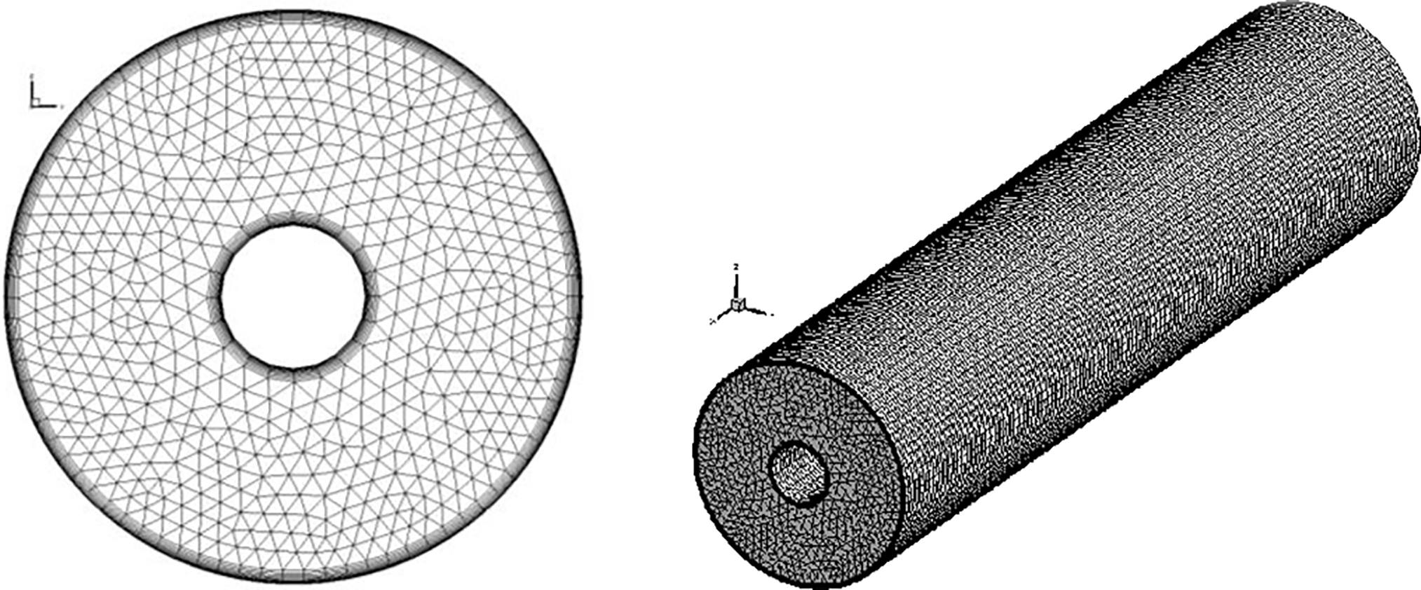
Figure 1: Physical model and meshing (not to scale)
In addition to the physical models mentioned above, this paper makes the following assumptions: the working fluid is a Newtonian fluid; there is no radiation; the effects of gravity and other body forces are neglected. The average value of physical quantities in the flow field does not change over time, i.e., the flow field is in a steady state.
2.2 Governing Equations and Boundary Conditions
The tensor forms of the continuity equation, momentum equation, and energy equation for this three-dimensional elliptical problem are shown in Eqs. (2)–(4). There are also equations for turbulent kinetic energy, its dissipation rate from the realizable κ–ε model, as well as those for the turbulent viscosity coefficient.
In Eqs. (2)–(12) [27,28], σκ and σε represent the turbulent Prandtl number for turbulent kinetic energy and its dissipation rate, respectively. As the default constant in Fluent, C2 = 1.9, σT = 0.85, σκ = 1.0, and σε = 1.2.
Using the velocity inlet, the outlet was set to a pressure outlet. The pipe walls were stationary walls, and the fluid velocity at the walls was zero, indicating no-slip conditions. The heating section had a constant wall temperature boundary condition.
2.3 Computational Models and Numerical Methods
In practical calculations, a turbulence model is selected based on the specific problem, preferably one that is simple to apply, versatile, non-computationally intensive, and highly accurate. For heat transfer in turbulent flow in pipes, Shao et al. [29] compared the frictional resistance obtained from various turbulence models with experimental values. They found that the κ–ε model and Reynolds stress model were suitable for turbulent flow in smooth pipe regions when using near-wall model methods for the near-wall region. Hossein Zolfagharnasab et al. [30] found that the realizable κ–ε model encountered fewer convergence difficulties compared with the Reynolds stress model when studying porous embedded shell-and-tube heat exchangers. Refs. [27,28] showed that the three κ–ε models shared the same basic framework and were all centered on solving the transport equations for turbulent kinetic energy and its dissipation rate. However, the three models differed in their ability to handle turbulent characteristics and in their model constants. The standard κ–ε model assumes that turbulence is isotropic, and the model constants are a set of fixed empirical values. The RNG κ–ε model considers that turbulence is anisotropic, and its model constants are determined through theoretical derivation and numerical computation. This allows them to be adapted to different flow conditions. The realizable κ–ε model performs better when dealing with flows with a higher degree of streamline curvature because it can automatically adjust the characteristics of turbulence according to the flow conditions, making it more in line with actual physical processes. Similarly, its model constants fully account for the physical nature of turbulence during derivation, which allows the model constants to better adapt to various complex flow conditions. This article presents a numerical simulation of turbulent convective heat transfer within a concentric annular pipe using the realizable κ–ε model based on the above considerations.
A low Reynolds number model was used in the near-wall region. The finite volume method was employed to solve the discretized equations, a third-order accurate QUICK format was used to discretize the convection terms, and a staggered grid along with the SIMPLE algorithm was adopted for the coupled solution of velocity and pressure. During the calculations, the velocity and pressure correction values were subjected to sub-relaxation. The velocity relaxation factor and pressure relaxation factor met the criterion of αu + αp = 1 [31].
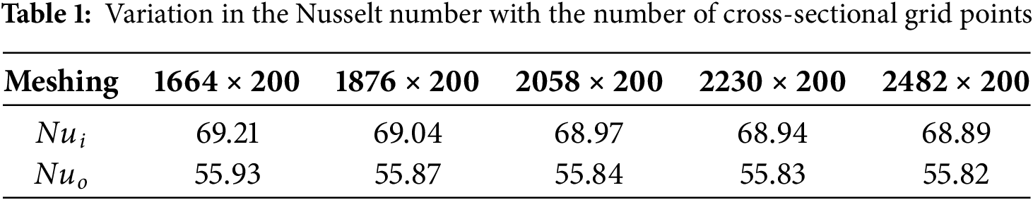
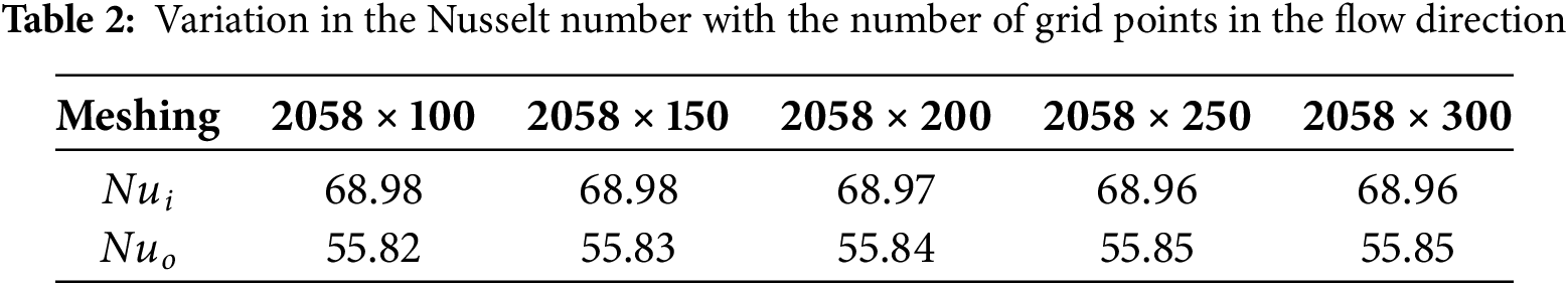
To ensure accuracy calculation results, this paper conducted a grid independence verification for each set of operating conditions after assessing the dimensionless distance between the first internal node and the wall, denoted as
The average temperature of the fluid on the cross-section and the logarithmic mean temperature difference are given as follows:
The local convective heat transfer coefficient and Nusselt number are given as follows:
where q represents the heat flux density through the wall surface; Tw represents the wall surface temperature; λ denotes the thermal conductivity of the fluid.
The Darcy resistance coefficient and Reynolds number for turbulent flow in the pipe is given as follows:
where µ represents the dynamic viscosity of the fluid.
The Blasius formula, Filonenko formula, Dittus-Boelter formula, and Gnielinski formula are as follows:
When heating the fluid, n = 0.4; when cooling the fluid, n = 0.3.
In the range of 104 – 1.2 × 10⁵, seven different Reynolds number groups were selected for numerical simulations of turbulent convective heat transfer in a circular pipe. The numerical results indicated that the relative errors between the Darcy resistance coefficient and the values calculated using the Blasius equation [14] and the Filonenko equation [6] were within 8.04% and 10.03%, respectively. The absolute values of the relative errors between the Nusselt number for turbulent heat transfer and the value calculated using the Dittus-Boelter equation and Gnielinski equation were 6.43% and 6.96%, respectively. The numerical simulation results were in good agreement with those from experimental correlation calculations, indicating that the numerical methods and mesh division strategy used in this study are reliable. Fig. 2 compares the Nusselt number for turbulent heat transfer in a circular pipe obtained from the realizable κ–ε model simulations with the values calculated from experimental correlations.

Figure 2: Comparison of simulated Nusselt numbers for a circular tube versus experimental correlation values
Simulations were used to study the turbulent convective heat transfer in five concentric annular pipes with inner-to-outer diameter ratios of 0.1, 0.2, 0.25, 0.5, and 0.8, as well as a circular tube. Fig. 3 compares the simulated Darcy friction factors for six types of pipes with their values calculated from experimental correlations. Fig. 3 shows that the Darcy resistance coefficient of the concentric circular pipe decreased as the Reynolds number increased. At the same Reynolds number, the Darcy friction factor increased as the inner-to-outer diameter ratio increased. At low Reynolds numbers, the slope of the curve was relatively large, and there were significant differences in Darcy friction coefficients among the various pipes. As the Reynolds number increased, the curve tended to flatten out, and the differences in Darcy resistance coefficients among the pipes diminished. The simulated Darcy resistance coefficients for six types of pipes followed the same trend as those calculated from the experimental correlation, further demonstrating the accuracy of the numerical method used in this paper.
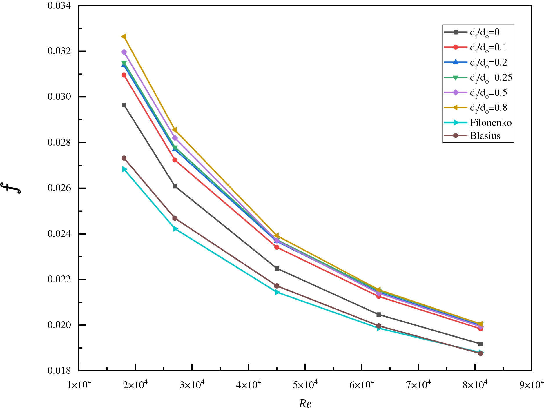
Figure 3: Comparison of the simulated Darcy resistance coefficients of six channels with experimental correlation values
Fig. 4 shows variations in the local surface heat transfer coefficient on the inner and outer wall surfaces using a concentric annular pipe with an inner-to-outer diameter ratio of 0.25 as an example. For the concentric annular pipe, the local heat transfer coefficient of the inner wall surface was generally higher than that of the outer wall surface. After a noticeable peak in the local surface heat transfer coefficient on the inner wall surface, it gradually stabilized, while the outer wall surface showed a gentler trend. The lengths of the entrance sections for the inner and outer wall surfaces were different. The outer wall surface reached a fully developed state more quickly, while the inner wall surface required a longer entrance section. After entering the fully developed stage, the local surface heat transfer coefficients on both the inner and outer walls stabilized, as did the heat transfer. Due to geometric constraints, the local turbulence intensity on the inner wall surface of the concentric annular duct was higher, and the heat transfer capability was significantly better than that of the outer wall surface. The heat transfer coefficient of the outer wall surface was low. Industrial design must consider potential uneven thermal stress distributions to avoid local overheating or corrosion.
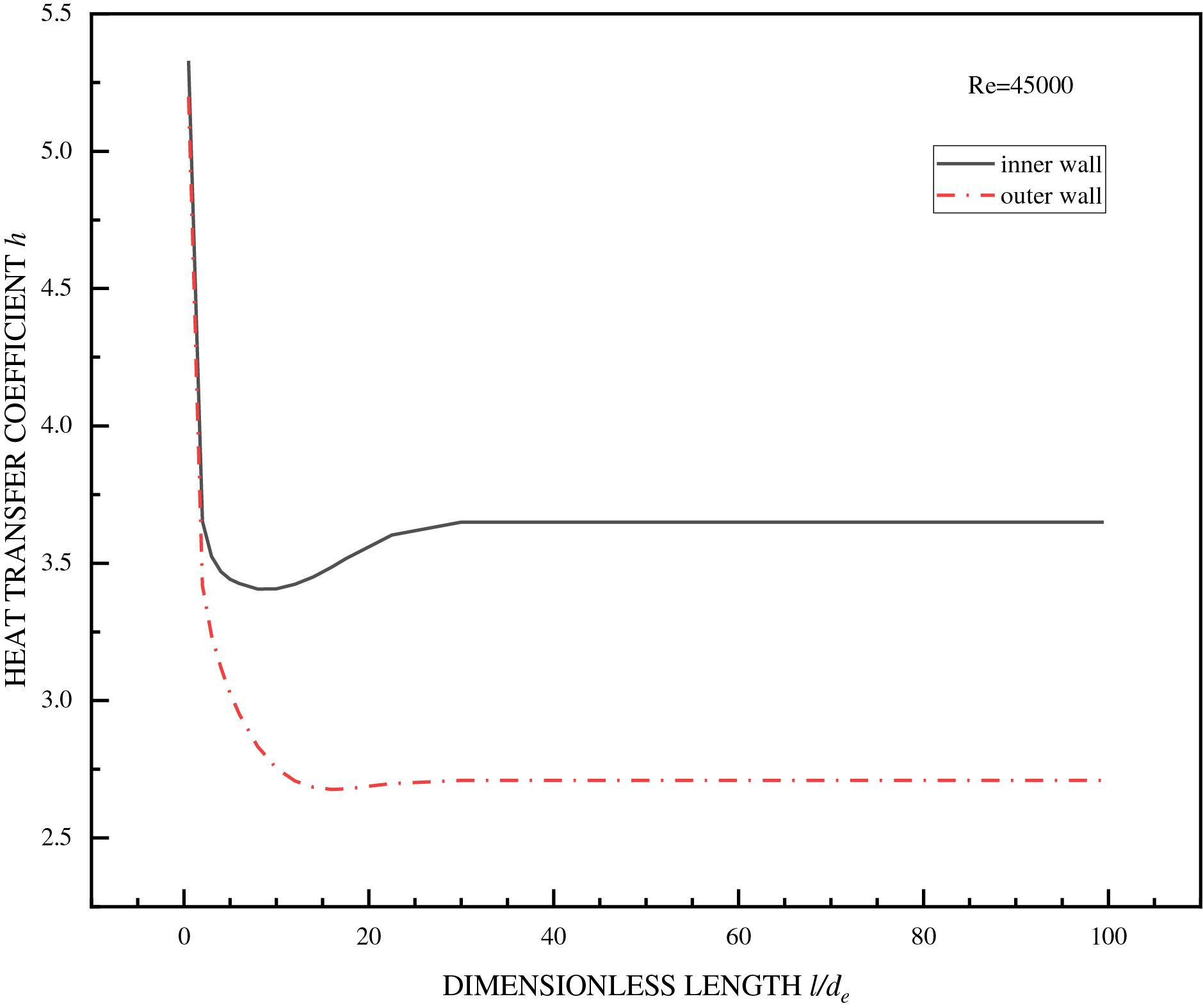
Figure 4: Comparison of heat transfer coefficients on the inner and outer wall surfaces of concentric annular pipes
Fig. 5 shows a scatterplot of the dimensionless ratio of the Nusselt number on the inner and outer surfaces of five concentric annular ducts to the Nusselt number of a circular duct under the same Reynolds number. The Nusselt number of the circular pipe was used as the datum line, with a value of 1. A fitted line was obtained to reflect the ratio of the heat transfer characteristics between the concentric annular pipe and the circular pipe. In Fig. 5, Nucir was the value calculated using the Dittus-Boelter equation. In the concentric annular pipe, the heat transfer Nusselt number on the inner wall decreased upon increasing the inner-to-outer diameter ratio, while that on the outer wall increased. However, its rate of change was not as significant as that of the inner wall, as shown by the notably smaller slope of the curve in Fig. 5b than that in Fig. 5a.


Figure 5: Dimensionless ratio of Nusselt number in concentric annular pipes to that in a circular pipe: (a) inner wall surface; (b) outer wall surface
The numerical calculation results indicated that significant errors were produced when using the equivalent diameter as the characteristic scale to calculate the turbulent convective heat transfer in a concentric annular pipe with the correlation obtained from a circular pipe produced. When the inner and outer diameters were small, this error was more pronounced on the inner wall surface, where the Nusselt number error reached 60.62%. The error of the Nusselt number on the outer surface reached 19.51%. Edris Bagheri [32] conducted direct numerical simulations on the turbulent convective heat transfer in concentric annular pipes. Their results showed that the different curvature caused the boundary layer on the outer wall surface to be thicker than that on the inner wall surface. The heat transfer capability of the inner and outer wall surfaces was significantly different. However, the author found that the Nusselt numbers of the inner and outer wall surfaces of the concentric annular pipe calculated using the Dittus-Boelter equation were the same. This also confirmed that using the equivalent diameter and the Dittus-Boelter equation for approximate calculations in turbulent heat transfer of concentric annular pipes introduced significant errors, consistent with our findings.
This article employed realizable κ–ε and low-Reynolds-number models to perform numerical simulations of turbulent convective heat transfer in concentric annular pipes with different inner-to-outer diameter ratios and circular pipes. The results showed that the local heat transfer coefficient and Nusselt number on the inner wall surface of the concentric circular pipe were both higher than those on the outer wall surface. The heat transfer capability of the inner wall surface was significantly better than that of the outer wall surface, and the lengths of the entrance sections for the inner and outer wall surfaces were different. The outer wall surface reached a fully developed state more quickly, while the inner wall surface required a longer entrance section. The Darcy resistance coefficient decreased upon increasing the Reynolds number and increased upon increasing the inner-to-outer diameter ratio. Using the correlation calculated with equivalent diameter and circular pipe experiments to determine the turbulent convective heat transfer in a concentric annular pipe resulted in significant errors. This error was more pronounced on the inner wall surface, especially when the inner and outer diameters were relatively small, and the Nusselt number error on the inner wall surface reached 60.62%.
Acknowledgement: Not applicable.
Funding Statement: Supported by the Major Program of the National Natural Science Foundation of China (Grant No. 51736007).
Author Contributions: The authors confirm contribution to the paper as follows: Conceptualization, methodology, validation, formal analysis, data curation, writing—original draft preparation, visualization, Jinping Xu; Software, Zhiyun Wang, Jinping Xu; Investigation, resources, Mo Yang, Jinping Xu; Writing—review and editing, Mo Yang, Zhiyun Wang, Jinping Xu; Supervision, project administration, Mo Yang. All authors reviewed the results and approved the final version of the manuscript.
Availability of Data and Materials: Data available within the article.
Ethics Approval: Not applicable.
Conflicts of Interest: The authors declare no conflicts of interest to report regarding the present study.
Nomenclature
| Heat capacity (J/(kg·K)) | |
| Equivalent diameter (m) | |
| Turbulent kinetic energy (m2/s2) | |
| Duct length (m) | |
| Wetted perimeter (m) | |
| Pressure (Pa) | |
| Nusselt number | |
| Reynolds number | |
| Prandtl number | |
| Heat flux (W/m2) | |
| Velocity (m/s) | |
| Temperature (K) | |
| Greek Symbols | |
| Turbulent dissipation rate (m2/s3) | |
| Thermal conductivity (W/(m∙K)) | |
| dynamic viscosity (kg/(m∙s)) | |
| Eddy or turbulent viscosity (kg/(m∙s)) | |
| Density (kg/m3) | |
| Turbulent kinetic energy Prandtl number | |
| Turbulent dissipation rate Prandtl number | |
| Turbulent energy Prandtl number | |
| Subscripts | |
| Inner wall | |
| Outer wall | |
| Circular pipe | |
References
1. Xu K, Hao YP, Wu DY. Resistance calculation and simulation analysis of annular pipeline. J Chang Inst Technol. 2015;16(2):51–5. doi:10.3969/j.issn.1009-8984.2015.02.014. [Google Scholar] [CrossRef]
2. Lu YJ, Peng YS, Ge ZH, Zhao PH. Large eddy simulation to study turbulent heat transfer of liquid metal in an annular pipe. J Univ Sci Technol China. 2015;45(11):917–22. doi:10.3969/j.issn.0253-2778.2015.11.006. [Google Scholar] [CrossRef]
3. Dittus FW, Boelter LMK. Heat transfer in automobile radiators of the tubular type. Int Commun Heat Mass Transf. 1985;12(1):3–22. doi:10.1016/0735-1933(85)90003-x. [Google Scholar] [CrossRef]
4. Bejan A. Street network theory of organization in nature. J Adv Transp. 1996;30(2):85–107. doi:10.1002/atr.5670300207. [Google Scholar] [CrossRef]
5. Peterson GP, Ortega A. Thermal control of electronic equipment and devices. In: Hartnett PJ, Irvine TF, editors. Advances in heat transfer. Amsterdam, The Netherlands: Elsevier; 1990. p. 181–314. doi:10.1016/s0065-2717(08)70028-5. [Google Scholar] [CrossRef]
6. Gnielinski V. New equations for heat and mass transfer in turbulent pipe and channel flow. Int Chern Eng. 1976;16:359–68. [Google Scholar]
7. Gnielinski V. On heat transfer in tubes. Int J Heat Mass Transf. 2013;63:134–40. doi:10.1016/j.ijheatmasstransfer.2013.04.015. [Google Scholar] [CrossRef]
8. Lienhard JH. A Heat transfer textbook. 3rd ed. Cambridge, MA, USA: Phlogiston Press; 2001. [Google Scholar]
9. Al-Lami AJS, Kenig EY. New pressure drop and heat transfer correlations for turbulent forced convection in internally channeled tube heat exchanger ducts. Case Stud Therm Eng. 2024;54:103993. doi:10.1016/j.csite.2024.103993. [Google Scholar] [CrossRef]
10. Sun DX. The applicable range, defect and correction of equivalent diameter used hydraulic diameter. J Eng Thermophys. 1987;8(4):357–62. (In Chinese). [Google Scholar]
11. Wang SS, Xu WQ, Hu YH. Characterization of convective heat transfer and flow resistance in elliptical tubes. Industrial Heating. 2010;39(4):13–6. (In Chinese). doi:10.3969/j.issn.1002-1639.2010.04.004. [Google Scholar] [CrossRef]
12. Qiao L. Numerical simulation of turbulent flow and heat transfer in a channel with rectangular cross section [dissertation]. Shanghai, China: University of Shanghai for Science and Technology; 2015. (In Chinese). [Google Scholar]
13. Kong QY, Li ML, Xiao Y, Liu JT. Analysis and study of turbulent heat transfer in high temperature and high pressure gas tubes. Energy Conserv Basic Sci. 2023;42(7):39–42. (In Chinese). doi:10.3969/j.issn.1004-7948.2023.07.011. [Google Scholar] [CrossRef]
14. Wang P, Yang M, Wang Z, Zhang Y. A new heat transfer correlation for turbulent flow of air with variable properties in noncircular ducts. J Heat Transf. 2014;136(10):101701. doi:10.1115/1.4027855. [Google Scholar] [CrossRef]
15. Yang M, Lv HT, Zhao YS, Lu TK, Dai ZH. Numerical experiments on turbulent convective heat transfer in a longitudinally swept tube bundle and its correlation equation. J Univ Shanghai Sci Technol. 2017;39(2):110–3. (In Chinese). doi:10.13255/j.cnki.jusst.2017.02.002. [Google Scholar] [CrossRef]
16. Yang M, Wang X, Wang Z, Li Z, Zhang Y. Correlation for turbulent convection heat transfer in elliptical tubes by numerical simulations. Front Heat Mass Transf. 2018;11:1–6. doi:10.5098/hmt.11.7. [Google Scholar] [CrossRef]
17. Babus’Haq RF. Forced-convection heat transfer from a pipe to air flowing turbulently inside it. Exp Heat Transf. 1992;5(3):161–73. doi:10.1080/08916159208946439. [Google Scholar] [CrossRef]
18. Sadeghi HM, Babayan M, Chamkha A. Investigation of using multi-layer PCMs in the tubular heat exchanger with periodic heat transfer boundary condition. Int J Heat Mass Transf. 2020;147(5):118970. doi:10.1016/j.ijheatmasstransfer.2019.118970. [Google Scholar] [CrossRef]
19. Yin Y, Nong Y, Li Y, Liu S. Enhanced heat transfer and flow resistance characteristics of twisted tube double-pipe heat exchangers. CIESC J. 2024;75(10):3528–35. doi:10.11949/0438-1157.20240459. [Google Scholar] [CrossRef]
20. Sun L, Fu B, Wei M, Zhang S. Analysis of enhanced heat transfer characteristics of coaxial borehole heat exchanger. Processes. 2022;10(10):2057. doi:10.3390/pr10102057. [Google Scholar] [CrossRef]
21. Konduru RN, Farges O, Schick V, Hairy P, Gaillard Y, Parent G. Experimental and numerical investigation of porous heat exchangers with Kelvin cell structured foam at high temperatures: coupled conduction-convection and radiation heat transfer. Int J Heat Mass Transf. 2024;224(25):125253. doi:10.1016/j.ijheatmasstransfer.2024.125253. [Google Scholar] [CrossRef]
22. Eldin SM, Alanazi M, Alanazi A, Alqahtani S, Alshehery S, Anqi AE. Economic and thermal analysis of a tubular thermoelectric power generator equipped with a novel fin-pin-porous based heat exchanger; comparative case study with conventional smooth channel. Case Stud Therm Eng. 2023;48(8):103166. doi:10.1016/j.csite.2023.103166. [Google Scholar] [CrossRef]
23. Li N, Chen J, Cheng T, Klemeš JJ, Varbanov PS, Wang Q, et al. Analysing thermal-hydraulic performance and energy efficiency of shell-and-tube heat exchangers with longitudinal flow based on experiment and numerical simulation. Energy. 2020;202:117757. doi:10.1016/j.energy.2020.117757. [Google Scholar] [CrossRef]
24. Ahmad Jamil M, Goraya TS, Shahzad MW, Zubair SM. Exergoeconomic optimization of a shell-and-tube heat exchanger. Energy Convers Manag. 2020;226(93):113462. doi:10.1016/j.enconman.2020.113462. [Google Scholar] [CrossRef]
25. Safari V, Kamkari B, Abolghasemi H. Investigation of the effects of shell geometry and tube eccentricity on thermal energy storage in shell and tube heat exchangers. J Energy Storage. 2022;52:104978. doi:10.1016/j.est.2022.104978. [Google Scholar] [CrossRef]
26. Serrano D, Sánchez-Delgado S, Pérez-Álvarez R, Acosta-Iborra A. Experimental determination of the convection heat transfer coefficient in an eccentric annular duct. Exp Therm Fluid Sci. 2022;136:110664. doi:10.1016/j.expthermflusci.2022.110664. [Google Scholar] [CrossRef]
27. Tao WQ. Numerical heat transfer. 2nd ed. Xi’an, China: Xi’an Jiaotong University Press; 2001. p. 227–370. (In Chinese). [Google Scholar]
28. Jiang F, Huang P. Fluent advanced applications and case analysis. Beijing, China: Tsinghua University Press; 2008. p. 14–5. [Google Scholar]
29. Shao J, Li XH, Guo ZJ, Liu RJ, Tian XL. Study on the applicability of different turbulence models in numerical simulation of pipeline flow. Chem Equip Pip. 2016;53(4):66–71. (In Chinese). [Google Scholar]
30. Hossein Zolfagharnasab M, Zamani Pedram M, Hoseinzadeh S, Vafai K. Application of Porous-Embedded shell and tube heat exchangers for the Waste heat Recovery Systems. Appl Therm Eng. 2022;211(11):118452. doi:10.1016/j.applthermaleng.2022.118452. [Google Scholar] [CrossRef]
31. Demirdzic I, Gosman AD, Issa RI, Peric M. A calculation procedure for turbulent flow in complex geometries. Comput Fluids. 1987;15(3):251–73. doi:10.1016/0045-7930(87)90009-0. [Google Scholar] [CrossRef]
32. Bagheri E, Wang BC. Direct numerical simulation of turbulent heat transfer in concentric annular pipe flows. Phys Fluids. 2021;33(5):055131. doi:10.1063/5.0047531. [Google Scholar] [CrossRef]
Cite This Article
 Copyright © 2025 The Author(s). Published by Tech Science Press.
This work is licensed under a Creative Commons Attribution 4.0 International License , which permits unrestricted use, distribution, and reproduction in any medium, provided the original work is properly cited.
 Downloads
 Citation Tools