
 Submit a Paper
 Propose a Special lssue
 Open Access
ARTICLE
An Investigation on the Thermal-Hydraulics Performance of a Bubble Column Reactor Fitted with Tube Bundle under Different Gas Sparger Configurations
1 College of Mechanical and Electronic Engineering, Fujian Agriculture and Forestry University, Fuzhou, 350002, China
2 Fujian Key Laboratory of Agricultural Information Sensing Technology, Fujian Agriculture and Forestry University, Fuzhou, 350002, China
* Corresponding Author: Changliang Han. Email:
Frontiers in Heat and Mass Transfer 2025, 23(4), 1103-1128. https://doi.org/10.32604/fhmt.2025.068181
Received 22 May 2025; Accepted 25 June 2025; Issue published 29 August 2025
 View Full Text
 Download PDF
Abstract
Bubble column reactors fitted with tube bundles (BCR TB) belong to common heat transfer equipment in the field of chemical engineering, yet the complicated thermal-hydraulics performance of BCR TB has not been deeply revealed. To fill this gap, the present study proposes a novel variable bubble size modeling approach based on the Euler-Euler two-fluid framework, which is coupled with the population balance model considering comprehensive interphase forces. On the basis of verifying numerical reliability using experimental data, the mechanism of bubble swarm flow around the tube bundle and the effects of gas sparger configurations on the thermal-hydraulics performance of BCR TB are investigated. Results indicate that the entire tube bundle can be divided into three distinct zones, namely the sparger effect zone, fully developed zone and interface effect zone in view of the local mixture-to-wall heat transfer coefficient. The maximum peak value of the mixture-to-wall heat transfer coefficient always appears at 210° of heat exchange tubes. When the orifice diameter is 4 mm, the axial gradient of gas holdup is relatively large due to more intense shearing and fragmentation effects. Interestingly, the fractions of medium-sized and large-sized bubbles are not sensitive to orifice angle. Both the mixture-to-wall heat transfer coefficient and the friction factor decrease initially and then increase when the installation height increases. Under the optimized gas sparger structure configuration, the mixture-to-wall heat transfer coefficient increases by 10.23%, accompanied by the reduction of pressure drop by 8.14%, ultimately attaining a system energy conversion efficiency of 97.88% and performance evaluation criterion of 1.087. Finally, a new dimensionless and semi-theoretical Nusselt correlation incorporating a structural correction factor with an average absolute deviation of 5.15% is developed. The findings can offer useful guidance for the optimal design of BCR TB.Graphic Abstract
Keywords
Bubble column reactors (BCRs) are widely utilized in various industrial settings and feature a cylindrical column with a gas sparger located at its bottom [1,2]. Under normal conditions, BCRs offer numerous advantages, such as low operating costs, high liquid holdup, and excellent mixing characteristics [3–5]. The above-mentioned reactors can be broadly classified into those with internal components and those without. However, the majority of existing studies have focused on BCRs without internals, primarily air-water systems [6–9]. Our previous findings indicate that adding internals (such as a tube bundle) to BCR can significantly improve thermal efficiency and reduce flow dead zones [10]. It is asserted that the BCR with tube bundle (BCR TB) facilitates heat and mass transfer through the bubble swarm flow around tubes. Moreover, the thermal-hydraulics performance of BCR TB is very complex since it is always operated under a heterogeneous regime, which is characterized by multiscale bubble swarm size distribution (BSD) and intense turbulence. Furthermore, the thermal efficiency of BCR TB is also very sensitive to gas sparger configurations. However, the quantitative analysis concerning these factors has not been fully conducted thus far, particularly involving orifice diameter (D), orifice angle (θ) and installation height (H, vertical distance between branch tube and the first row of tube bundle). Therefore, systematic investigations into multiscale bubble swarm flow around a tube bundle and the thermal-hydraulics behavior under different gas sparger configurations are essential for optimizing BCR TB performance.
Previously, a large number of studies about the thermal-hydraulics performance of BCR without internals have been conducted thanks to advanced numerical and experimental methods [11–14]. Li et al. [15] developed an improved population balance model (PBM) to thoroughly consider the hydrodynamic behavior of pilot-scale slurry BCR. The influences of gas sparger parameters on system properties were analyzed. It turned out that an increase in orifice and ring diameters could be beneficial to increasing gas holdup (εg) and enhancing bubble swarm breakage effects. The Euler-Euler two-fluid approach was proposed by Varallo et al. [16] to investigate the hydrodynamic performance of BCR under the heterogeneous regime. The obtained outcomes indicated that introducing lift force was helpful in predicting the radial distribution of εg, particularly the complete model significantly improved BSD prediction accuracy. Yang et al. [17] adopted PBM to study the resistance correction of a rising bubble swarm inside a BCR. It was concluded that there existed wake acceleration effects for the bubble swarm. In addition, this coupled model could well predict the complicated mass transfer behavior of high-viscosity liquids. Draw and Rzehak [18] studied the hydrodynamic performances of gas-liquid two-phase flow inside a BCR. The following conclusions were drawn under the condition of low εg, the gas phase pressure gradient played a leading part in the relative velocity. At high εg, the bubble swarm coalescence effect needed to be considered. It was also found that the lift force exerted a significant influence on the distribution of εg. Khan et al. [19] conducted a comparative analysis of different drag models for the prediction of gas-liquid two-phase flow inside a BCR. It was discovered that for smaller bubble swarm sizes, the Ishii and Zuber model could exhibit comparable prediction accuracy to the Tomiyama model. Zhang et al. [20] explored the universality of PBM for the prediction of BCR performance. Under different operating parameters, the εg, BSD, interfacial area and volumetric mass transfer coefficient showed good consistency with experimental data. These results demonstrated that the numerical methodology could effectively describe the breakage and coalescence effects of a rising bubble swarm. An et al. [21] carried out an investigation into the effects of mild agitation on the bubble swarm inside a slurry BCR. Under the heterogeneous regime, the bubble swarm size diminished initially and then augmented. Bae et al. [22] investigated the effect of micro-bubble formation and dual gas on the mixture-to-wall heat transfer coefficient (h) of pressurized BCR. The study concluded that h decreased with increasing micro-bubble concentration and further decreased with reduced opening ratios under the pressurized conditions.
For BCRs with internals, Guan et al. [23] studied the effect of helical finned tube internals on the gas-liquid flow inside a laboratory-scale BCR. It was observed that compared with bare tube internals, the BSD was more uniform when helical finned tube internals were installed. Decreasing the liquid phase velocity could effectively reduce back-mixing and enhance mixing efficiency through small-scale vortices. Abdel-Gawad et al. [24] experimentally investigated the heat and mass transfer performance of BCR fitted with horizontal helical tubes under the bubbling flow regime. Results indicated that the helical tubes were beneficial for alleviating the axial dispersion problem and raising the system production rate. Córcoles et al. [25] conducted an investigation on the thermal-hydraulics behavior of a bubbling fluidized bed fitted with a tube bundle. Results demonstrated that for different tube bundle configurations, h was the lowest in the top zone of tubes. It also indicated that h of the staggered layout was higher. Shen et al. [26] performed a study on the heat transfer process of liquid metal flowing around a helical tube bundle. Both the friction factor (f) and Nusselt number (Nu) increased when the helical angle was augmented. A smaller tube pitch could effectively improve the heat transfer capacity of liquid metal. Ji et al. [27] discussed the effects of baffle structures on the heat transfer properties of heat exchangers fitted with an elastic tube bundle. It showed that increasing baffle height could suppress vibration and fluid pressure drop (ΔP). Meanwhile, an increase in the baffle curvature might impair the thermal efficiency. An et al. [28] conducted a numerical simulation about the distribution of solid particles inside a slurry BCR by utilizing PBM. Results displayed that the PBM could be used to enhance the prediction precision of BSD in a solid-free system to a certain extent. PBM coupled with an attenuation factor accurately predicted εg and critical ΔP variations. Fard et al. [29] investigated the large-scale vortical flow phenomenon induced by a bubble swarm inside a BCR. It was discovered that the large eddy numerical model could well reproduce the experimental phenomena in the core regions.
To sum up, although extensive research concerning the hydrodynamic and thermodynamic behavior of BCR has been conducted, most studies only considered drag force and lift force, while the lubrication force and turbulent diffusion force are always ignored. This treatment results in significant deviations in predicting the underlying mechanism of multiscale bubble swarm flow around a tube bundle, especially the influences of gas sparger configurations on the thermal-hydraulics performance of BCR TB require further investigation. To fill these gaps, in the present work, a novel variable bubble size modeling (VBSM) approach based on the Euler-Euler two-fluid model coupled with PBM is developed (see Fig. 1), which considers the comprehensive interphase force interactions of the bubble swarm. In view of this methodology, three typical heat transfer zones of BCR TB are identified as the first step. Distributions of local h, vertical velocities of gas phase (vy,g) and bubble swarm streamlines are also investigated. Then the variation trends of thermal-hydraulics parameters (εg, BSD, h and f) under different gas sparger structural parameters are clarified. The energy conversion efficiency (η) and performance evaluation criterion (PEC) are quantified for the optimized parameters. Finally, a new dimensionless and semi-theoretical Nusselt correlation incorporating a structural correction factor is proposed for BCR TB. This work provides a robust framework for studying multiscale bubble swarm flow around a tube bundle and offers critical insights for the optimal design of BCR TB systems.
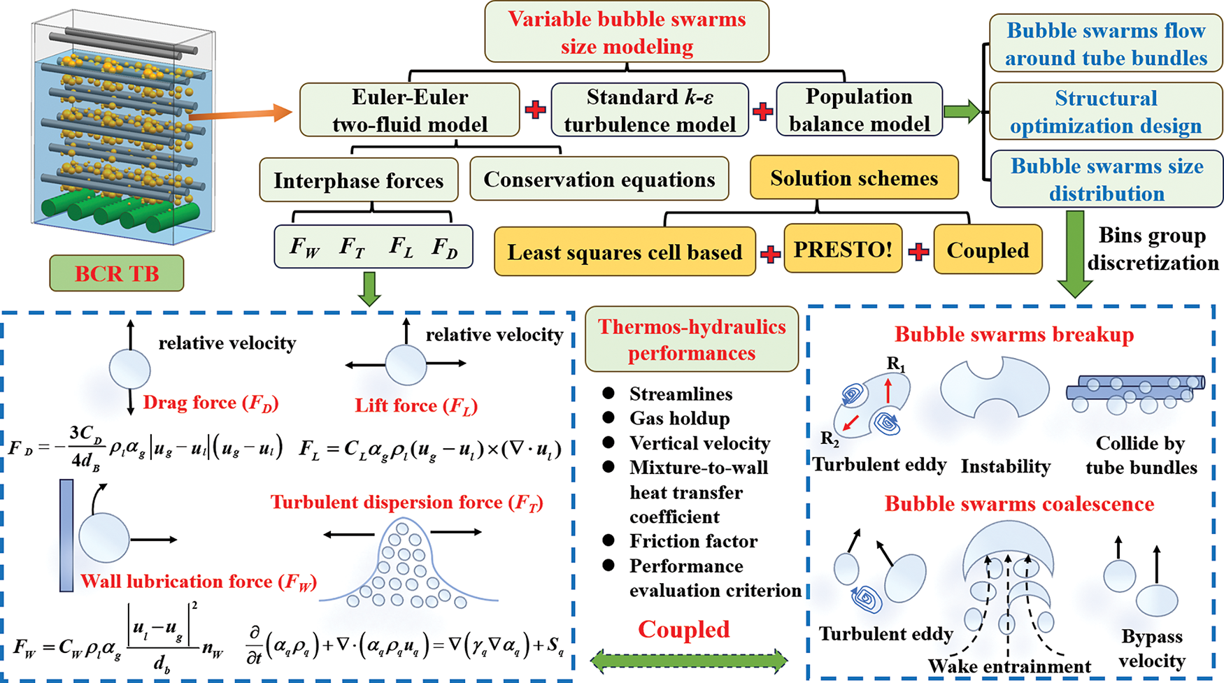
Figure 1: Schematic diagram of developed variable bubbles size modeling approach
Fig. 2 illustrates the entire computational domain of the present BCR TB. The high-temperature gas phase is ejected through a gas sparger into BCR TB containing liquid phase at room temperature. Gas phase heats liquid phase in the form of a bubble swarm and simultaneously exchanges heat with the tube bundle walls. Due to the obstruction of the tube bundle, the fragmentation and coalescence phenomena occur frequently, which bring about complicated heat transfer mechanisms of multiscale bubble swarm flow around tube bundle. As depicted in Fig. 2a, the overall physical structure mainly consists of three configurations, namely gas sparger, tube bundle and column. Along the flow direction (from bottom to top) of the multiscale bubble swarm, the tube bundle zone comprises 16 rows and 3 columns of heat exchanging tubes. For the sake of convenience, the tube bundle is clearly numbered from 1 to 8. Three representative cross-sectional planes are selected for subsequent analysis. In addition, the label of each tube is defined as “Tube row-column”. Fig. 2b displays that the gas sparger mainly consists of 3 branch tubes, each of which contains 3 uniformly distributed orifice rows. Notably, air and water are respectively specified as the incompressible gas phase and liquid phase. It is assumed that the thermal properties of gas phase change minimally due to moderate hydrostatic pressure variations along the height of column. The thermal properties of liquid phase are evaluated at the atmospheric pressure.
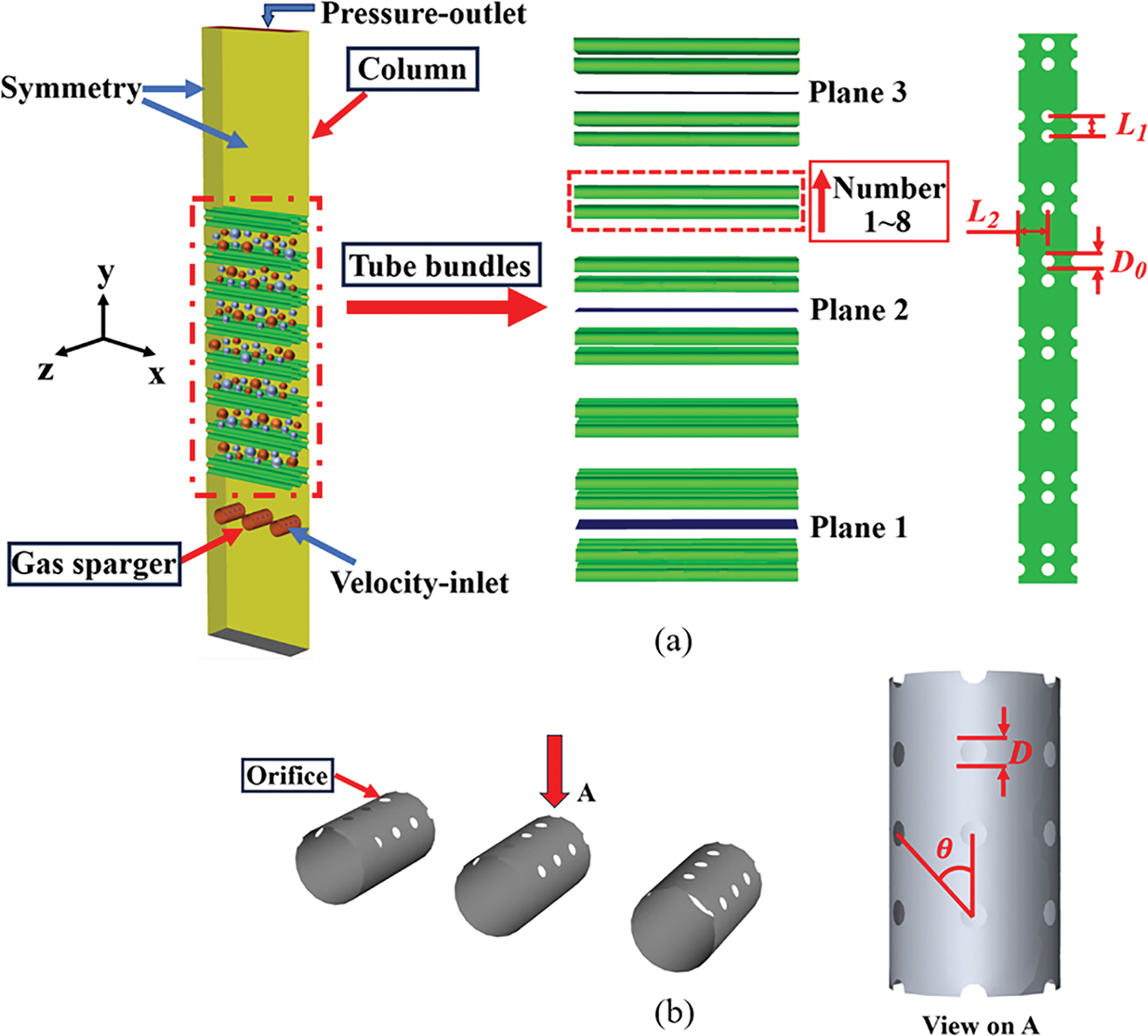
Figure 2: Schematic diagram of computational domain. (a) Entire physical structure. (b) Composition of gas sparger
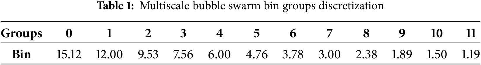
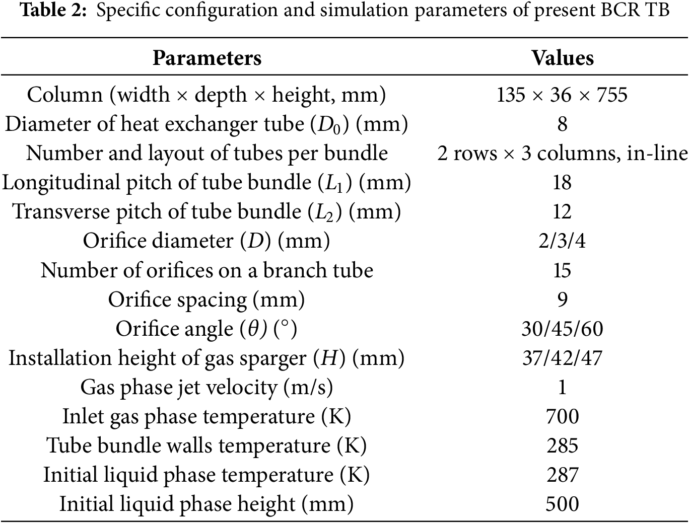
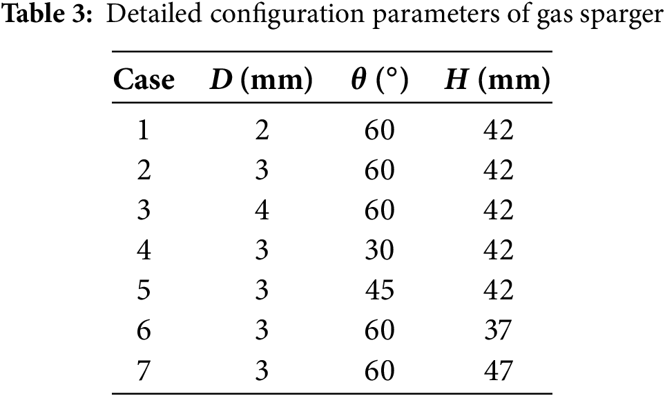
Reasonable boundary conditions are the foundation for obtaining proper numerical results. In the present paper, the velocity-inlet boundary condition is assigned at the orifices, where the inlet volume fraction of the gas phase is set to 1. The turbulence intensity level is set to 5%. It shall be noted that while finer discretization of multiscale bubble swarm diameter improves BSD accuracy, it significantly increases computational costs. Therefore, the multiscale bubble swarm is divided into 12 diameter groups ranging from 1.19 to 15.12 mm, with the initial diameter assigned to Bin 7 (see Table 1). A pressure-outlet boundary condition is set for the top face of the column. The atmospheric pressure and the complete backflow condition of gas phase are fixed. No-slip and constant temperature boundary conditions are applied to tube bundle walls. Symmetry boundary conditions are applied to the front, back, left, and right faces of the column. The specific configuration and simulation parameters of BCR TB are summarized in Table 2. Additionally, seven gas sparger configurations are selected to investigate different thermal-hydraulics performance of BCR TB. Specific parameters are clearly listed in Table 3.
For the present multiscale bubble swarm flow around the tube bundle inside BCR TB, the physical process can be considered as a time-dependent and non-equilibrium multi-phase fluid flow. Compared with the common Volume of Fluid (VOF) and Mixture models, the Euler-Euler two-fluid framework is more suitable for describing this issue with higher prediction accuracy [30]. This methodology solves separate sets of governing equations for each phase, and the interphase coupling relationship is established through interaction coefficients.
2.2.1 Euler-Euler Two-Fluid Model
Continuity equation,
Momentum equation,
Energy equation,
The precise prediction of multiscale bubble swarm flow fields determines the reliability of simulation results. Based on previous research, the standard k-ε turbulence model is utilized to calculate the time-averaged Reynolds stress tensor [31]. This model can provide reasonably accurate predictions regarding BSD at a lower computational cost. The equations are shown as follows:
k equation,
ε equation,
G is the generation rate of turbulent kinetic energy. Cε1 = 1.44, Cε2 = 1.92, Cμ = 0.09, σk = 1.0, σε = 1.3.
It must be pointed out that the accuracy of numerical results is also highly associated with the selected interphase force models, such as drag and lift force models, wall lubrication force model, and virtual mass force model. Due to the excellent performance in predicting the polydispersity of bubble swarm under heterogeneous regimes, the Ishii and Zuber model [32] is selected to calculate the drag force. The model incorporates the interactions of bubble swarm through semi-empirical correlations. Its equation is given as follows:
Drag coefficient (CD) is the most critical parameter in calculating FD. The Schiller and Naumann model [33] can be suitable for computing CD, which divides the relative Reynolds number (Re) into two ranges. Its expression is shown as follows:
Lift force (FL) is perpendicular to the flow direction of the bubble swarm, which is mainly induced by the asymmetric flow of the bubble swarm. The present FL is employed as the term proposed by Jin et al. [34]. Its form is given as follows:
Given the ability to describe lateral forces caused by asymmetric flow of bubble swarm, the Tomiyama model [35] is adopted to calculate the lift force. This model explicitly correlates the lift coefficient (CL) with Re and modified Eötvös number (Eo), which makes it suitable for predicting bubble swarm flow around a tube bundle with larger velocity gradients. It can be given as follows:
Turbulent dispersion force (FT) results in the dispersion of bubble swarm from high-concentration regions to low-concentration regions. The diffusion-in-VOF model [36] is selected to describe FT because it explicitly relates the turbulent viscosity to bubble swarm concentration gradient. This approach is particularly suitable for modeling the dispersion of bubble swarms in high-turbulence regions, where small-scale eddies dominate the coalescence and breakup of bubble swarms. Its expression is as follows:
Among them, ∇(γq∇αq) is the turbulent diffusion term. γq is the diffusion coefficient, which can be calculated using turbulent viscosity:
Under the default conditions, σq = 0.75.
Wall lubrication force (FW) involves the concentration of multiscale bubble swarm near the walls without adhering to surface, which pushes bubble swarm away from wall. The FW model proposed by Antal et al. [37] is utilized to describe the repulsion phenomenon of bubble swarm. It calculates the repulsive force based on BSD and the distance to wall. The expression is given as follows:
CW refers to the wall lubrication force coefficient, its expression is obtained as follows:
CW1 = −0.01, CW2 = 0.05, db is the bubble swarm diameter, yw is the distance to wall.
A series of population balance equations are utilized to predict complex BSD inside tube bundle zone. The governing equations of PBM [38] are displayed as follows:
c(V – V′, V′) is the coalescence kernel function, b(V′) is the breakage kernel function, a (V, V′) is the coalescence efficiency of bubbles with volumes V′ and V, β(V|V′) is the probability that a bubble with volume V breaks into a bubble with volume V′.
The Luo coalescence model [39] is employed, which describes bubble swarm coalescence probability through the competition mechanism between turbulent eddy collision frequency and liquid film drainage time. This model is also suitable for characterizing the evolution of BSD dominated by the coupled breakage-coalescence effects. It quantifies coalescence behavior via the physical correlation between collision frequency and coalescence efficiency of the bubble swarm.
The Luo and Svendsen breakage model [40] predicts breakup behavior based on the dynamic equilibrium between turbulent eddy kinetic energy and surface energy, which can accurately capture the physical phenomenon of high-turbulence gas-liquid systems. It establishes a framework for breakup processes using breakage frequency and daughter BSD function as the core variables.
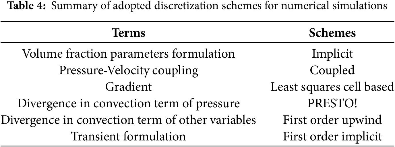
Transient 3D numerical simulation is conducted using commercial software ANSYS Fluent 2022. In the software, the above-mentioned governing equations are solved by the two-phase flow solver. This solver discretizes the equations based on the finite volume method, which is well-suited for transient two-phase flow simulation. The time step size is set to 0.005 s as an optimized value so that the Courant-Friedrichs-Lewy number [41] can be lower than 1. To highlight the variation trends and average behaviors of gas-liquid flow within a relatively long time-scale, the simulation results are presented as time-averaged values. Table 4 summarizes the discretization schemes adopted for the present numerical investigation.
To quantify the thermal-hydraulics performance of BCR TB, the key parameters, including η, f and PEC can be derived from numerical results. This section presents the mathematical formulas used to calculate these parameters. These formulas serve as the basis for evaluating the impact of gas sparger configurations and validating the proposed VBSM framework. The definitions of each parameter are clearly stated as follows:
The Nu is given as:
where λ is thermal conductivity of multi-phase fluids.
The time-average h is given as:
where q represents the heat flux, Tf and Tw respectively represent multi-phase fluids temperature and tube bundle walls temperature.
The f is estimated by:
where ΔP is the pressure drop of BCR TB, which can be obtained by:
where Pin and Pout refer to the fluid hydrostatic pressures at the inlet and outlet.
The η is estimated by:
where Qin and Qout represent the total heat at the inlet and outlet.
The PEC in the present work is given by:
where Nu0 and f0 represent the selected base-line values.
The absolute average of deviation (AAD) of Nu can be obtained by:
Gambit software (Gambit 2.4.6) is adopted for pre-processing to generate 3D hybrid mesh elements, as illustrated in Fig. 3. The majority of elements are hexahedral with low skewness, and their skewness is below the threshold of 0.4. In order to reduce the computational cost and improve computational accuracy, the block partitioning strategy is utilized to generate the elements near the gas sparger and tube bundle zones. Furthermore, a mesh independence analysis is conducted under the condition where D = 3 mm, θ = 60° and H = 42 mm. Five groups of mesh systems are generated with the number ranging from 82,941 to 935,860. The calculated Nu and f are shown in Fig. 4. When the number of elements increases from 390,851 to 935,860, the variations of Nu and f gradually stabilize. Therefore, in order to avoid excessive consumption of computational resources, the mesh system with 390,851 elements is used for the subsequent simulations.
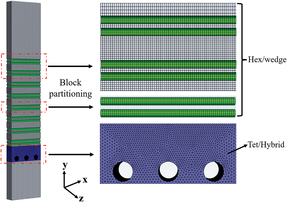
Figure 3: 3D hybrid mesh elements
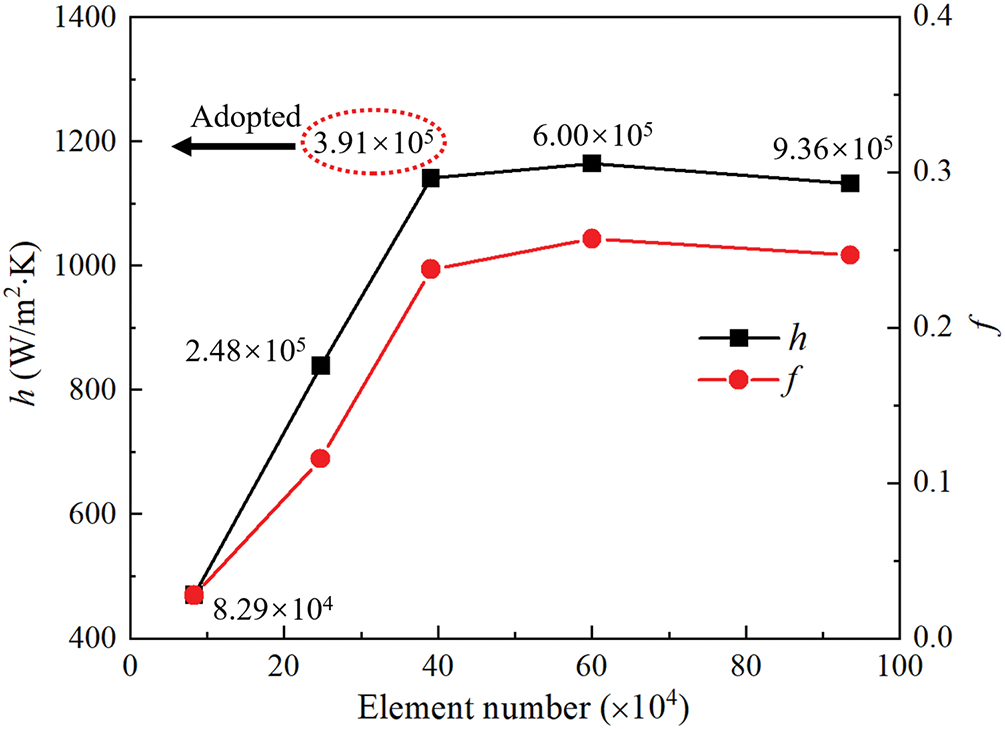
Figure 4: Mesh independence analysis
To ascertain the credibility and accuracy of the proposed VBSM, a validation study is performed using our previous experimental platform for BCR TB [42]. The numerical parameters are basically consistent with the experimental data. During the experimental process, conjugate heat transfer occurs among the gas phase, liquid phase, tube bundle walls and cold water. The obtained temperature values can be used as reasonable boundary conditions for numerical simulations. The detailed experimental procedure will not be repeated here. As is well known, εg is a comprehensive parameter that can be used to reflect the flow and heat transfer characteristics of multi-phase fluids. Fig. 5 illustrates the comparison of the average εg for different superficial gas phase velocities (Ug) and initial liquid phase heights (Hl,i) under the heterogeneous regime. It can be clearly seen that the calculated data utilizing the present VBSM are almost consistent with experimental results with small prediction deviations. As a matter of fact, the present VBSM can be applied to different BSD scenarios of BCR TB, which reflects the applicability of this advanced methodology to some extent. In summary, the complex thermal-hydraulics performance of BCR TB can be further investigated by utilizing the present VBSM.
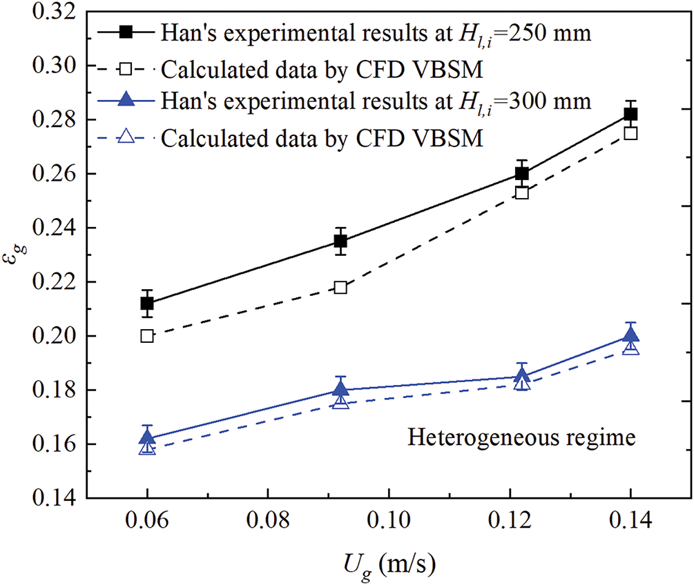
Figure 5: Comparisons of experiments results and calculated data about gas holdup by VBSM
3.1 Mechanism of Multiscale Bubble Swarms Flow around Tube Bundles
Similar to the thermal-hydraulics process of single-phase fluid flowing through tube bundle, the present tube bundle zone subjected to bubble swarm can be divided into three typical zones, namely the sparger effect zone, fully developed zone and free interface effect zone, as shown in Fig. 6. It can be seen that average h of the sparger effect zone is smaller than that of the fully developed zone. At this stage, gas phase has just been ejected from gas sparger, and both the size and the flow velocity of the multiscale bubble swarm are smaller due to the hindering effect. For the fully developed zone, bubble swarm flow trajectories are further altered due to the obstruction of the tube bundle. Near tube bundle walls, the radial velocity gradient in the liquid phase forms, which results in different pressures acting on the multiscale bubble swarm. Bubble swarm is deflected from a straight upward path by lateral forces and flow around tube bundle. Additionally, average h of the fully developed zone increases and reaches a relatively stable value after passing through 3 rows of tubes. Because at this point the coalescence rate of the multiscale bubble swarm (dominating over fragmentation) increases, which induces an increase in the fraction of large bubbles. For the free interface effect zone, average h further increases after 7 rows of tubes. The reason may be that when the multiscale bubble swarm approaches the unstable free interface, a large pressure gradient forms, which causes violent fluctuations in the gas-liquid interface and enhances heat transfer.
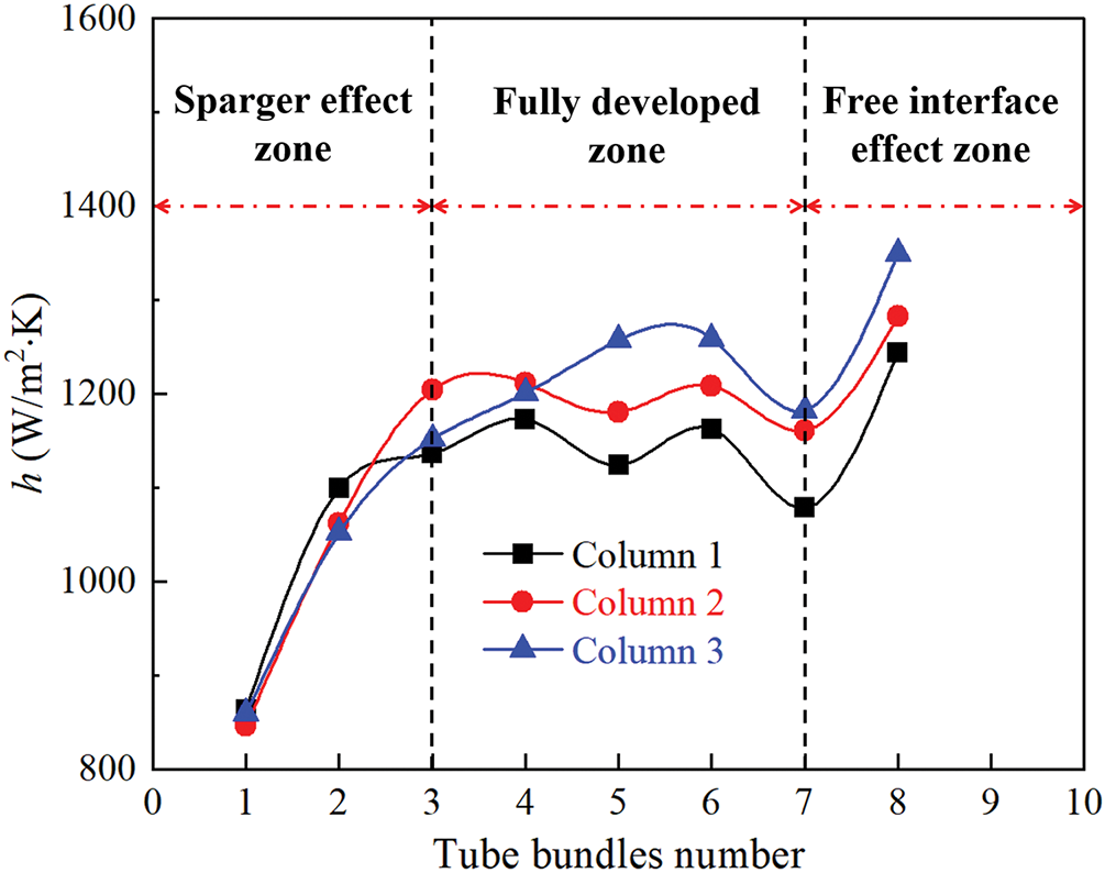
Figure 6: Mixture-to-wall heat transfer coefficient distribution on three columns of tube bundle
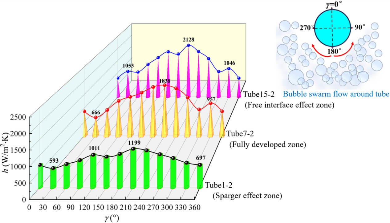
Fig. 7 displays the distributions of local h along the circumferential angle (γ) for different heat exchanging tubes; the selected tube bundle number is column 2. Results indicate that local h inside different zones generally shows a trend of increasing initially and then diminishing, with the peak value always appearing at 210°. The flow velocity is higher on the windward side, resulting in stronger turbulence intensity and higher h. When the multiscale bubble swarm reaches the leeward side, the flow velocity decreases and the turbulence level diminishes, which is conducive to reducing heat transfer efficiency. For tube 1-2 (sparger effect zone), as the flow velocity is relatively small and the bubble swarm size presents uneven distribution, the h of this zone is relatively low. In comparison, for tube 7-2 (fully developed zone), a fully heterogeneous flow forms, and breakup and coalescence effects of the bubble swarm mainly result from turbulent eddy collisions [43]. When flow velocity further increases, the multiscale bubble swarm is prone to deform and more likely to collide with tube bundle walls. For tube 15-2 (free interface effect zone), h further increases due to the rupture of bubble swarm near the free interface.
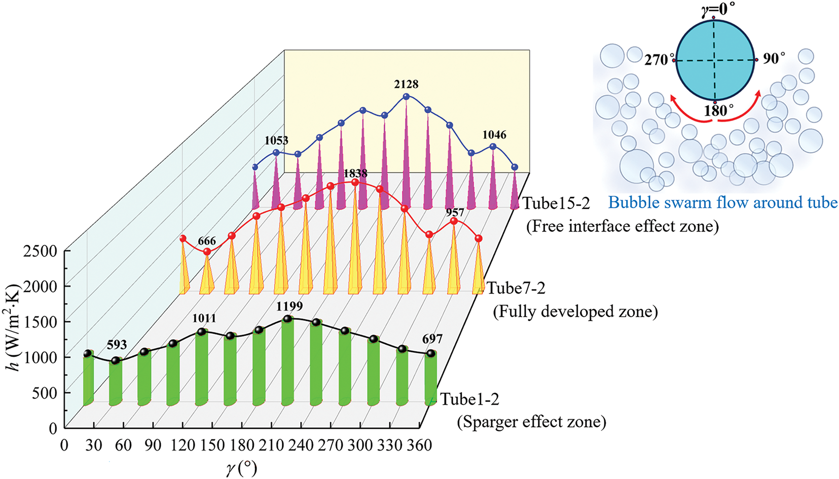
Figure 7: Distributions of local mixture-to-wall heat transfer coefficients for tube bundle
Fig. 8 depicts the predicted numerical contour of εg for BCR TB. Fig. 8a displays the overall εg at z = 9 mm. The results indicate that the tube bundle has a significant shear effect on the rising multiscale bubble swarm. The transverse lift force promotes the aggregation of large bubbles and pushes them towards the central area. A large number of bubbles emerge inside the entire tube bundle zone. Meanwhile, this shear effect leads to an enhanced mixing effect and the typical “bubble swarm column” phenomenon forms. The distributions of local εg on the three selected planes are shown in Fig. 8b. It can be seen that at plane 1 (sparger effect zone), the shape of bubble swarm is mainly flat, because bubble swarm is subjected to significant resistance. As the axial height increases, the shape undergoes significant changes due to the lift force. At plane 2 (fully developed zone), the shape of bubble swarm presents a circular ring. Bubble swarm tends to mix with each other. The interweaving of large and small bubbles inside this zone is beneficial for enhancing heat transfer. At plane 3 (free interface effect zone), the accumulating multiscale bubble swarm will disperse again due to the liquid phase reflux. Furthermore, an increase in turbulent kinetic energy facilitates the penetration of bubble swarm across the free interface.
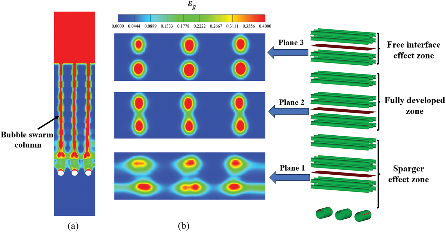
Figure 8: Predicted numerical contour of gas holdup. (a) Overall value on z = 9 mm. (b) Local value on different cross-sections
Fig. 9 shows the distribution of multi-phase fluid streamlines inside the tube bundle zone. From Fig. 9a, there exist typical vortical flow phenomena of multiscale bubble swarm which suggest obvious chaotic behaviors and intense radial migration. These vortices are almost dispersed throughout the entire zone. Further observation displays that the vortices with different sizes inside the fully developed zone are more pronounced, which is attributed to the self-aggregation effect. The distinctive feature is conducive to intense oscillatory fragmentation. Meanwhile, it can also reduce the boundary layer thickness of multiscale bubble swarm and enhance heat transfer. The simulated 2D vertical cut view of the axial liquid phase inside tube bundle zone is shown in Fig. 9b. It reveals that upward and downward velocity components near the tube bundle walls exist, which are accompanied by the formation of evident circulation phenomena, especially large circulations emerge with intense vorticity. Besides, the whole axial liquid phase velocity (vy,l) exhibits a periodic distribution.
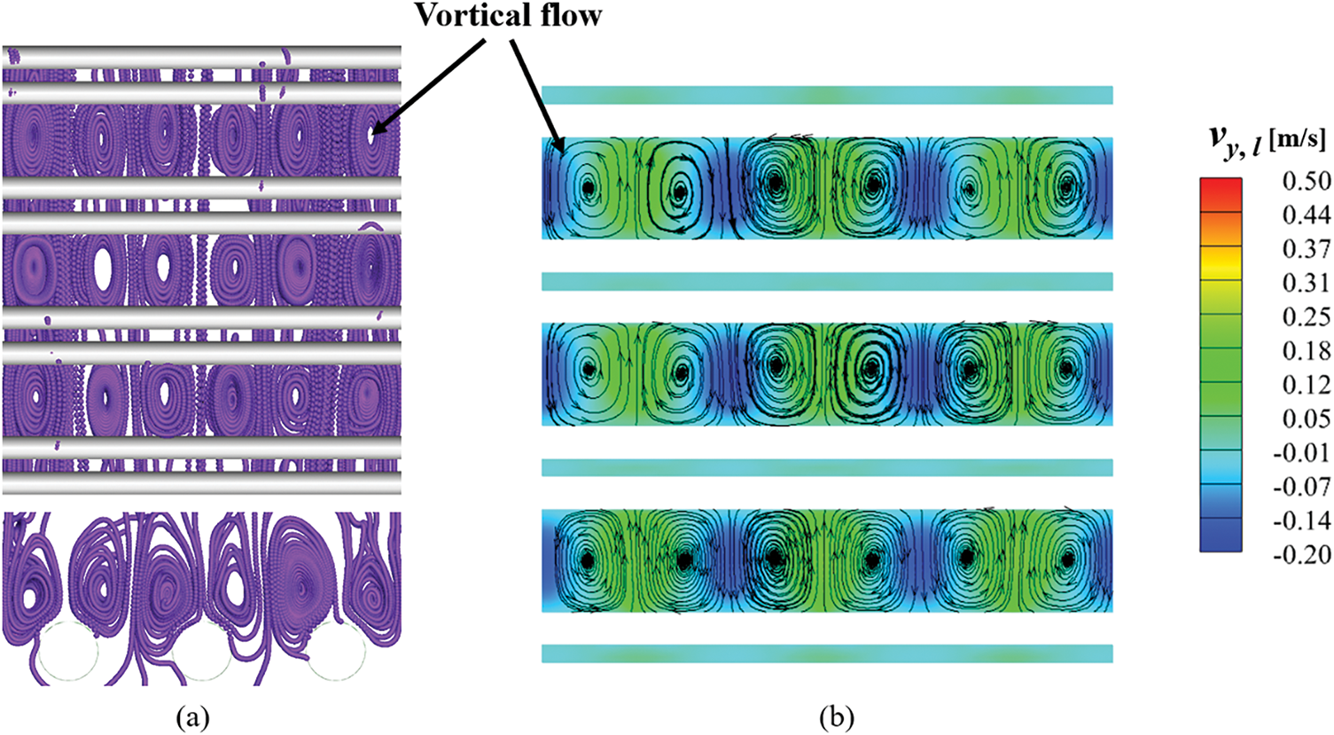
Figure 9: Distribution of multi-phase fluids streamlines. (a) 3D bubble swarm. (b) 2D vertical cut view of axial liquid phase
Fig. 10 depicts the distribution of vy,g along the horizontal direction of different cross-sections. It can be observed that vy,g exhibits a periodic distribution with a peak value reaching up to 70% of the inlet velocity. It is noted that the peak values almost appear directly above the gas sparger. The peak positions are approximately located near x = −0.045 m, x = 0 m and x = 0.045 m. At plane 1 (sparger effect zone), the frequency of bubble aggregation and fragmentation is higher, resulting in frequent collisions and lower vy,g. At plane 2 (fully developed zone), the aggregation frequency increases due to the “bubble swarm column” effect, which reduces rising resistance and consequently increases vy,g. At plane 3 (free interface effect zone), the multiscale bubble swarm in this zone must overcome significant resistance, leading to a decrease in vy,g. Quantitative calculations show that the average values of vy,g on three planes are respectively 0.42, 0.48 and 0.44 m/s.
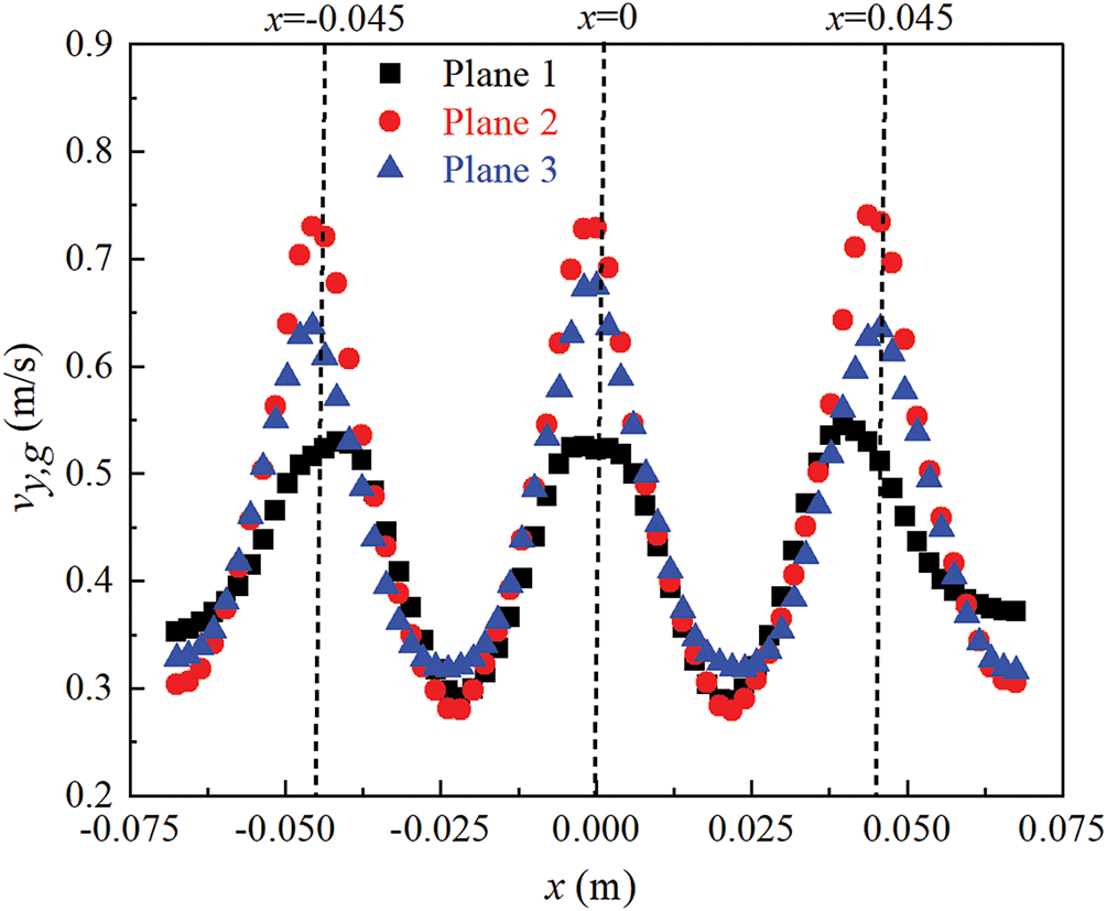
Figure 10: Vertical velocities of gas phase along horizontal direction on different cross-sections
Fig. 11 illustrates the horizontal BSD at three different cross-sections. It can be seen that BSD inside the sparger effect zone is considerably disordered. At this point, multiscale bubble swarm undergoes intense momentum exchange with the surrounding liquid. Furthermore, a multiscale bubble swarm is subjected to forces in different directions, which interfere with the coalescence process and make it difficult to form a regular distribution. Closer inspection shows that BSD inside the fully developed zone and free interface effect zone tends to be stable and presents three peak values. Furthermore, the bubble swarm size in both zones gradually increases, especially the growth rate in the fully developed zone is more significant. It can be attributed to the vortical flow within the tube bundle zone, which promotes the aggregation effect of bubble swarm. When the distance between bubbles is small enough, multiscale bubble swarm is more likely to coalesce under the action of surface tension.
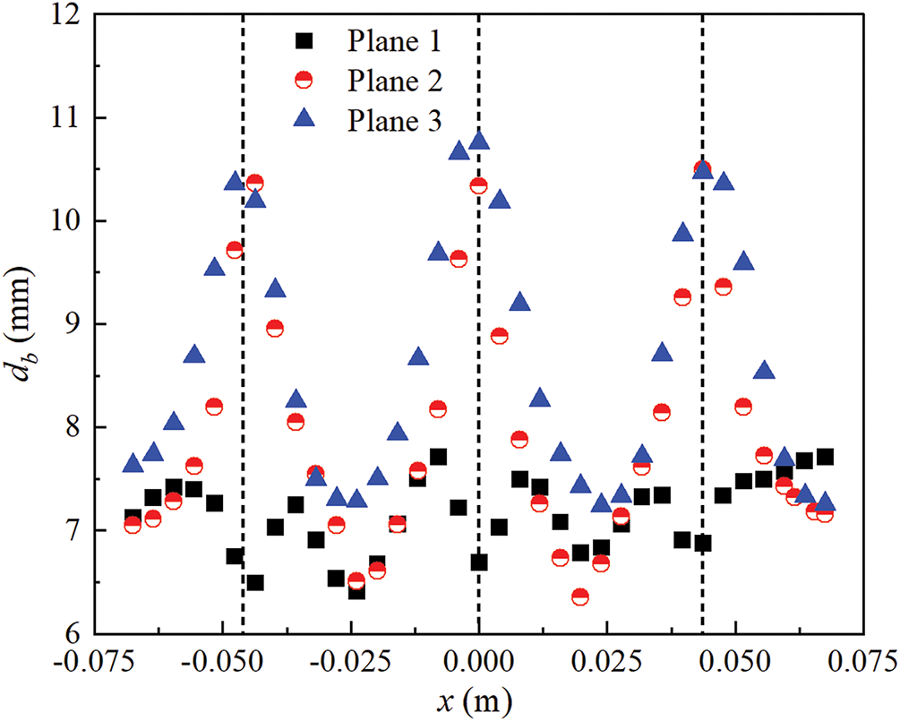
Figure 11: Bubble size distribution on different cross-sections along horizontal direction
3.2 Effects of Gas Sparger Configurations
3.2.1 Axial Gas Holdup Distribution
Fig. 12 provides a comparison of the predicted local and average axial εg under different gas sparger configurations. As shown in Fig. 12a, as D increases, the local and average axial εg first decrease slightly and then increase significantly. It occurs because an increase in D reduces the gas flow velocity. Accordingly, the upward velocity of the multiscale bubble swarm inside the liquid phase slows down. The increasing trend within sparger effect zone is more drastic compared to that of the fully developed zone and the free interface effect zone. When D = 4 mm, the axial distribution gradient of εg is larger, which indicates that this structural parameter is beneficial for enhancing heat transfer intensity. Fig. 12b considers the effect of θ on the local and average axial εg distribution. It shows that the distribution pattern of axial εg remains consistent across different θ. The variation of axial εg becomes moderate inside the sparger effect zone and the free interface effect zone. The larger θ, the smaller the average axial εg. That is because the initial injection area of the gas phase increases and results in a reduced probability of multiscale bubble swarm coalescence rate. When bubble swarm collides with tube bundle walls, such collisions promote the formation of higher εg. Fig. 12c displays the effects of H on the local and average axial εg distribution. It can be observed that as H increases, εg exhibits an initial decrease followed by an increase. This trend correlates with the prolonged residence time of multiscale bubble swarm. It has been calculated that the average εg values are respectively 0.095, 0.088 and 0.093.
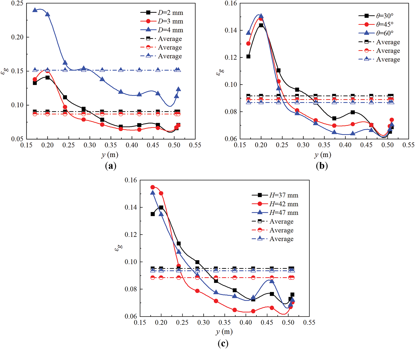
Figure 12: Comparison of predicted local and average axial gas holdup distribution. (a) Different orifice diameters. (b) Different orifice angles. (c) Different installation heights
3.2.2 Sauter-Mean Bubble Swarms Size
For the present multiscale bubble swarm flow around tube bundle, various Sauter-mean bubble swarm sizes can be classified as small-sized bubbles (db < 6 mm), medium-sized bubbles (6 mm < db < 10 mm) and large-sized bubbles (db > 10 mm) [44]. The comparison results of Sauter-mean bubble swarm size inside tube bundle zone are displayed in Fig. 13. From Fig. 13a, as D increases, the fraction of small-sized bubbles gradually decreases, and the fraction of medium-sized bubbles increases and then decreases, while the fraction of large-sized bubbles increases significantly. Further observation shows that when D = 4 mm, the Sauter-mean bubble swarm size tends to be consistent and uniform distribution, which is favorable for enhancing heat transfer. Fig. 13b compares Sauter-mean bubble swarm size under different θ. It can be seen that as θ increases, the fraction of small-sized bubbles reduces slightly, while θ has nearly no effect on the fractions of medium-sized and large-sized bubbles. In other words, multiscale bubble swarm aggregation and breakup effects are not sensitive to θ. As displayed in Fig. 13c, at determined H, there are mainly small-sized bubbles inside tube bundle zone, especially the fraction of large-sized bubbles is small. Additionally, the impact of H on the fraction of medium-sized bubbles is more pronounced.
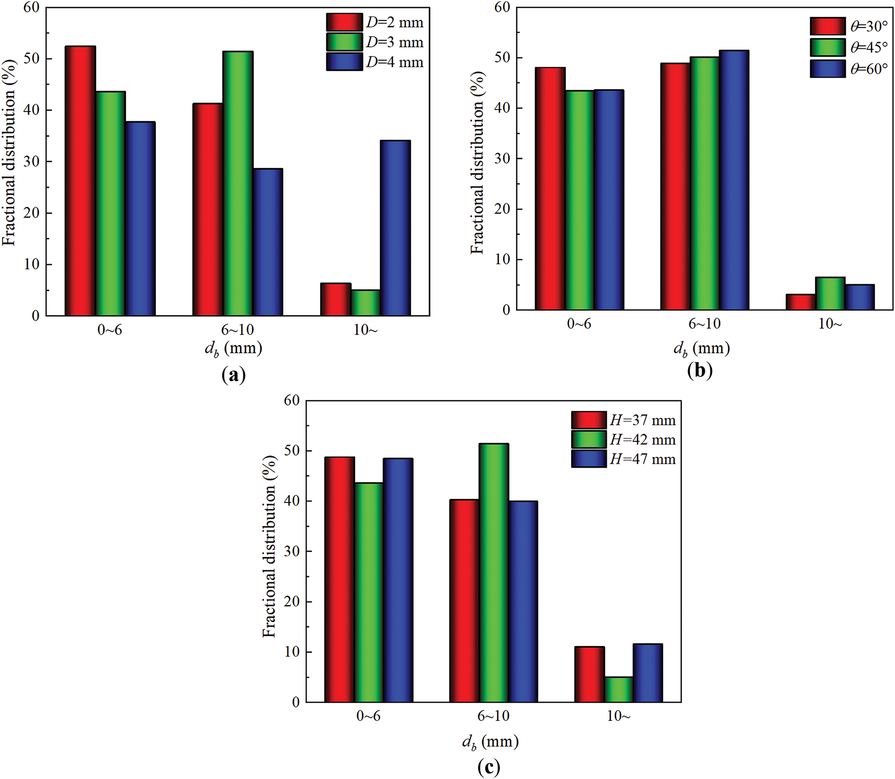
Figure 13: Comparison of predicted magnitude of Sauter-mean multiscale bubble swarm size distribution. (a) Different orifice diameters. (b) Different orifice angles. (c) Different installation heights
3.2.3 Mixture-to-Wall Heat Transfer Coefficient and Friction Factor
Fig. 14 shows the influences of gas sparger configuration parameters on h and f. From Fig. 14a, when D increases, the number of bubble swarm inside tube bundle zone increases and leads to an enhancement in h. However, an increase in D may increase the flow resistance of bubble swarm and result in a greater f. The trends in h and f under different θ are shown in Fig. 14b. As θ increases, both parameters inside the sparger effect zone gradually increase. Except for this zone, f gradually decreases with θ = 30° being an exception. Yet, the changing trend concerning f inside fully developed zone and free interface effect zone remains constant. The reason may be that the fraction of bubble swarm is not related to θ (see Fig. 13b). Fig. 14c illustrates multiscale bubble swarm exhibits the highest h when H = 42 mm, at this time f is also the highest. Hence, it is necessary to comprehensively consider these two aspects for the overall thermal-hydraulics performance of BCR TB.
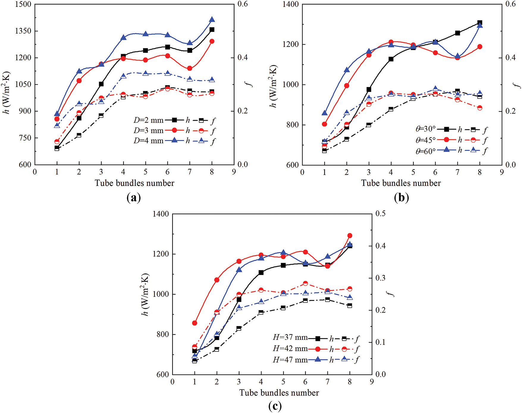
Figure 14: Comparison of predicted mixture-to-wall heat transfer coefficient and friction factor. (a) Different orifice diameters. (b) Different orifice angles. (c) Different installation heights
3.3 Comprehensive Thermos-Hydraulics Performance Analysis
As depicted in Fig. 15, Nu and ΔP exhibit similar changing trends under different gas sparger configuration parameters. Under the combined parameters of Case 3 (D = 4 mm, θ = 60°, H = 42 mm), Nu reaches the maximum value while ΔP is the minimum value. It may be that an increase in D leads to a more uniform BSD inside the tube bundle zone, which increases the effective heat transfer area. When D = 4 mm, the interfacial area of bubble swarm significantly increases and flow resistance is reduced. Furthermore, when compared with θ, the variation of H has a more significant impact on Nu and ΔP. The reason is that it affects the flow trajectory of bubble swarm and BSD as stated above.
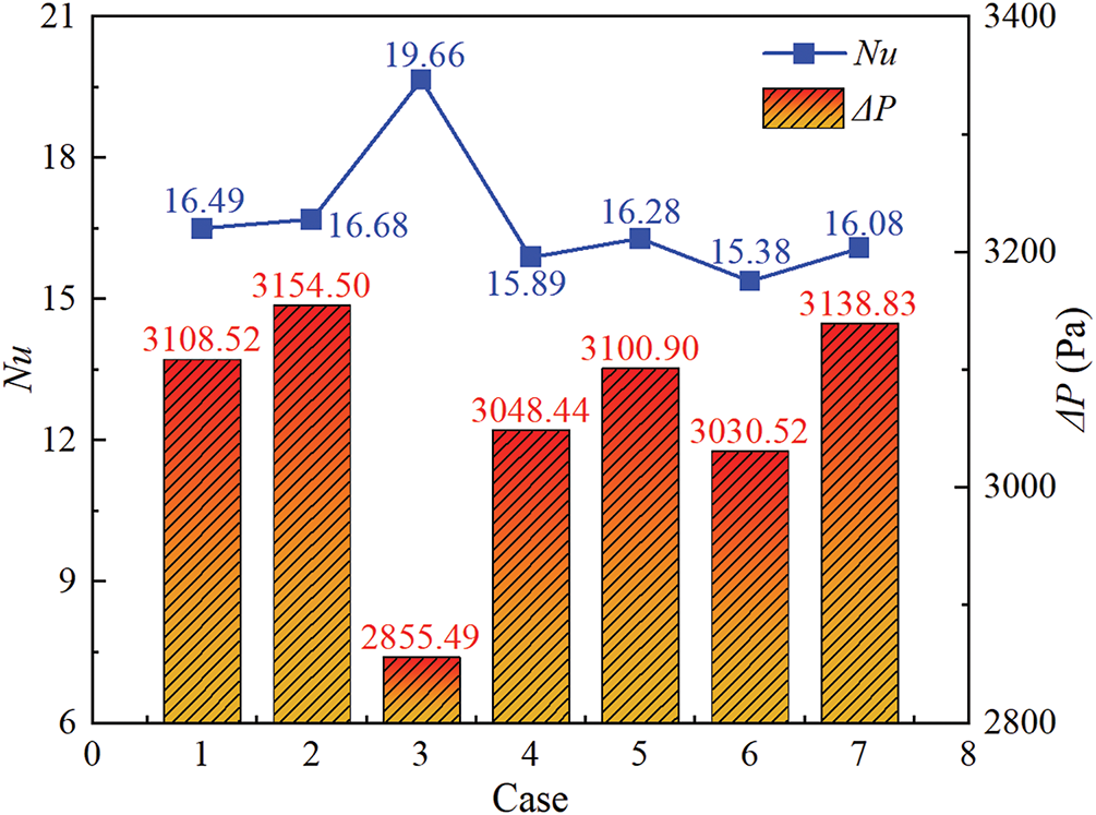
Figure 15: Variations of Nu and ΔP under different gas sparger configurations
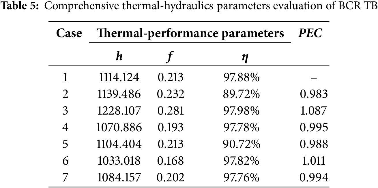
To further clarify the influence of gas sparger configurations on the thermal-hydraulics performance of BCR TB, an in-depth exploration is conducted in terms of η and PEC. Fig. 16 presents the variations in total heat at the inlet and outlet carried by the gas phase under different cases. It can be seen that under Case 3, the inlet and outlet heats carried by gas phase are respectively 272.71 and 5.52 W, and the maximum η of 97.98% can be achieved. Furthermore, Table 5 lists the comprehensive thermal-hydraulics parameters evaluation for BCR TB. Here, the configuration parameters of Case 1 are selected as the baseline, and PEC of six additional configurations is calculated and compared. Results show that the optimum PEC is 1.087. Notably, for combined parameters, D has a significant influence on PEC with the maximum deviation of 8.7%. In contrast, the variations of θ and H have a smaller impact on PEC, with a maximum deviation being only 1.7%.
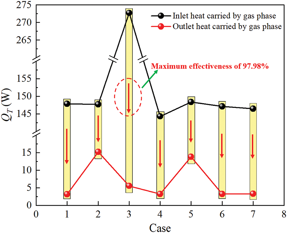
Figure 16: Variations of total heat at inlet and outlet carried by gas phase
3.4 Correlative Formula for Nusselt Correlation
Table 6 presents commonly used dimensionless Nu correlations for multi-phase fluid system. It is deduced by calculation that the AADs of Kim [45] and Ranz and Marshall [46] are 162.13% and 29.22%, respectively. Hence, the classical correlations are not suitable for predicting the thermal-hydraulics performance of present BCR TB. Furthermore, given that the heat transfer characteristics of BCR TB are influenced by the gas sparger configuration parameters, the present paper develops a new dimensionless and semi-theoretical correlation incorporating structural correction factors (D, θ, and H). The specific form of this correlation is given as:
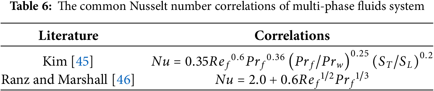
Fig. 17 presents the comparison results of predicted and numerical Nu. Evidently, the predicted Nu using the new correlation is in good agreement with simulated values within a tolerance of ±20%. Additionally, the AAD is calculated to be 5.15%. It implies that new correlation can be used for the optimal design of BCR TB to some extent. In future work, the ranges of investigated parameters will be expanded to improve the predictive ability of correlation equations.

Figure 17: Comparison results of predicted and numerical Nusselt number
In the present study, a novel variable bubble swarm size modeling approach is proposed to investigate the bubble swarm flow around the tube bundle inside BCR TB. Meanwhile, the effects of gas sparger configurations on the thermal-hydraulics performance are also comprehensively studied utilizing this advanced numerical method. The following conclusions can be drawn:
(1) A novel variable bubble size modeling approach, which combines the Euler-Euler two-fluid model, interphase force models, standard k-ε turbulence model and PBM, is more suitable for predicting the mechanism of multiscale bubble swarm flow around a tube bundle. The intrinsic relationship between gas sparger configurations and the thermal-hydraulics performance of BCR TB can be investigated with higher accuracy using this methodology.
(2) For multiscale bubble swarm flow around a tube bundle, the entire tube bundle can be divided into three typical zones, namely the sparger effect zone, the fully developed zone and the free interface effect zone. The average mixture-to-wall heat transfer coefficient of different zones generally increases first and then decreases, with the maximum peak value always appearing at 210° of heat exchange tubes. Under the action of the shear effects and transverse lift forces, a typical “bubble swarm column” phenomenon forms. There exists a typical vortical flow phenomenon around a tube bundle, which is conducive to enhancing heat transfer. On different cross-sections, the vertical gas phase velocities exhibit a periodic distribution along the horizontal direction, and the positions of peak values are always located directly above the gas sparger.
(3) When the orifice diameter is 4 mm, the multiscale bubble swarm exhibits stronger heat transfer intensity due to the larger axial gradient of the gas holdup. An increase in orifice diameter may increase the fluid flow resistance of the bubble swarm. For different orifice angles, the variations in axial gas holdup become moderate inside the sparger effect zone and free interface effect zone. The aggregation and breakup effects of a multiscale bubble swarm are not significantly affected by orifice angle. When the installation height increases to 42 mm, both the mixture-to-wall heat transfer coefficient and friction factor reach their maximum values.
(4) Compared with the orifice angle, the variation of installation height has a more significant influence on the Nusselt number and pressure drop. When the orifice diameter is 4 mm, the orifice angle is 60° and the installation height is 42 mm, the energy conversion efficiency and performance evaluation criterion of BCR TB are respectively 97.98% and 1.087. Moreover, a new dimensionless and semi-theoretical Nusselt correlation incorporating a structural correction factor with an average absolute deviation of 5.15% is developed. The present findings are empirical and require further verification with the aim of being confidently utilized by designers.
Acknowledgement: The authors would like to sincerely thank Fujian Agriculture and Forestry University for providing laboratory facilities support and financial support. The scientific calculations in this paper have been done on the HPC Cloud Platform of Fujian Provincial Key Laboratory of Agricultural Information Perception Technology.
Funding Statement: This work was supported by the project 2024J01421 supported by Fujian Provincial Natural Science Foundation.
Author Contributions: The authors confirm contribution to the paper as follows: conceptualization, investment, validation, writing—original draft, Yizhong Wu; supervision, resources, project administration, writing—review & editing, Changliang Han; validation, data curation, writing, Jianquan Xu; methodology, formal analysis, writing—review & editing, Long Ying; software, data curation, Kang Wang. All authors reviewed the results and approved the final version of the manuscript.
Availability of Data and Materials: Data can be provided on request.
Ethics Approval: Not applicable.
Conflicts of Interest: The authors declare no conflicts of interest to report regarding the present study.
Nomenclature
| BB,i, DB,i | Birth and death rate by bubble breakup, 1/s |
| BC,i, DC,i | Birth and death rate by bubble coalescence, 1/s |
| CD | Drag coefficient |
| CL | Transverse lift coefficient |
| CTD | Turbulent dispersion coefficient |
| CWL | Wall lubrication coefficient |
| de | Bubble diameter of e, mm |
| Eo | Eötvös number |
| FD | Drag force, N |
| FL | Transverse lift force, N |
| FT | Turbulent dispersion force, N |
| FW | Wall lubrication force, N |
| fv | Ratio of daughter bubbles to original bubbles |
| g | Gravity, m/s2 |
| H | Installation height of gas sparger, mm |
| H | Mixture-to-wall heat transfer coefficient, W/m2·K |
| K | Turbulent kinetic energy per unit mass, m2/s2 |
| Nu | Nusselt number |
| n (Vi, t) | Bubble density function |
| pc | Bubble collision efficiency |
| ΔP | Pressure drop, Pa |
| Q | Heat flux, W/m2 |
| Re | Reynolds number |
| T | Time, s |
| T | Temperature, K |
| V | Velocity, m/s |
| Greek Symbols | |
| εg | Gas holdup |
| τk | Stress, Pa |
| ξej | Ratio of bubble e to bubble j |
| ρ | Density, kg/m3 |
| ωc | Bubble coalescence efficiency |
| λ | Thermal conductivity, W/m·K |
| η | Energy conversion efficiency |
| Abbreviations | |
| AAD | Absolute average of deviation |
| BSD | Bubble swarm size distribution |
| BCR TB | Bubble column reactor fitted with tube bundle |
| PEC | Performance evaluation criteria |
References
1. Shen T, Lu D, Liu Z, Chen R, Gong M. Heat and mass transfer performance analysis of a vertical tubular ammonia/water bubble absorber based on CFD modeling. Appl Therm Eng. 2024;252(4):123622. doi:10.1016/j.applthermaleng.2024.123622. [Google Scholar] [CrossRef]
2. Pourghorban F, Rahimi-Ahar Z, Sadegh Hatamipour M. Performance evaluation of bubble column humidifier using various air distributors in a humidification-dehumidification desalination plant. Appl Therm Eng. 2023;227:120392. doi:10.1016/j.applthermaleng.2023.120392. [Google Scholar] [CrossRef]
3. Eder E, Hiller S, Brüggemann D, Preißinger M. Characteristics of air-liquid heat and mass transfer in a bubble column humidifier. Appl Therm Eng. 2022;209(4):118240. doi:10.1016/j.applthermaleng.2022.118240. [Google Scholar] [PubMed] [CrossRef]
4. Kotb M, Khalifa A, Hussein A, Alawad SM, Antar M. Performance and exergy analysis of vacuum-assisted sweeping air membrane distillation and bubble column dehumidifier. Appl Therm Eng. 2024;245:122800. doi:10.1016/j.applthermaleng.2024.122800. [Google Scholar] [CrossRef]
5. Ferrario A, Varallo N, Besagni G, Mereu R. Influence of the gas phase on a large-scale bubble column fluid dynamics: gas holdup, flow regime transitions, and bubble size distributions. Chem Eng Sci. 2025;302(1):120792. doi:10.1016/j.ces.2024.120792. [Google Scholar] [CrossRef]
6. Bhati A, Kar A, Bahadur V. Analysis of CO2 hydrate formation from flue gas mixtures in a bubble column reactor. Sep Purif Technol. 2024;330(7):125261. doi:10.1016/j.seppur.2023.125261. [Google Scholar] [CrossRef]
7. Zhu X, Feng X, Zou Y, Shen L. Effect of baffles on bubble behavior in a bubbling fluidized bed for chemical looping processes. Particuology. 2020;53(15):154–67. doi:10.1016/j.partic.2020.04.003. [Google Scholar] [CrossRef]
8. Bhusare VH, Dhiman MK, Kalaga DV, Roy S, Joshi JB. CFD simulations of a bubble column with and without internals by using OpenFOAM. Chem Eng J. 2017;317:157–74. doi:10.1016/j.cej.2017.01.128. [Google Scholar] [CrossRef]
9. Bokelmann C, Bromley J, Takors R. Pros and cons of airlift and bubble column bioreactors: how internals improve performance. Biochem Eng J. 2025;213(4):109539. doi:10.1016/j.bej.2024.109539. [Google Scholar] [CrossRef]
10. Han C, Huang Y, Guo W, Wu Y, Chen Z, Li X. Thermal-hydraulics performance evaluation of bubble swarms sweeping tube bundles in a direct contact gas-liquid-solid reactor. Appl Therm Eng. 2024;250(5):123478. doi:10.1016/j.applthermaleng.2024.123478. [Google Scholar] [CrossRef]
11. Kar A, Bahadur V. Analysis of coupled heat & mass transfer during gas hydrate formation in bubble column reactors. Chem Eng J. 2023;452(8):139322. doi:10.1016/j.cej.2022.139322. [Google Scholar] [CrossRef]
12. Mahmood AN, Abdulrahman AA, Sabri LS, Sultan AJ, Majdi HS, Al-Dahhan MH. Flow regimes in bubble columns with and without internals: a review. Fluid Dyn Mater Process. 2024;20(2):239–56. doi:10.32604/fdmp.2023.028015. [Google Scholar] [CrossRef]
13. Dhakane V, Mishra P, Yadav A. Computational fluid dynamics (CFD)-deep neural network (DNN) model to predict hydrodynamic parameters in rectangular and cylindrical bubble columns. Digit Chem Eng. 2024;13(3):100185. doi:10.1016/j.dche.2024.100185. [Google Scholar] [CrossRef]
14. Khadanga SP, Samal DK, Patnaik PK, Roy GK. Pressure-drop and mass transfer study in multi-stage PSRBC sparger bubble column—an experimental investigation. Int Commun Heat Mass Transf. 2024;153(1):107347. doi:10.1016/j.icheatmasstransfer.2024.107347. [Google Scholar] [CrossRef]
15. Li L, Zhang Q, Li X, Han C, Peng Z, Lian W, et al. Optimization of gas distributor to improve flow characteristics in a particular slurry bubble column reactor using CFD-PBM coupled method. Powder Technol. 2024;448:120244. doi:10.1016/j.powtec.2024.120244. [Google Scholar] [CrossRef]
16. Varallo N, Besagni G, Mereu R. Computational fluid dynamics simulation of the heterogeneous regime in a large-scale bubble column. Chem Eng Sci. 2023;280(12):119090. doi:10.1016/j.ces.2023.119090. [Google Scholar] [CrossRef]
17. Yang G, Zhang H, Luo J, Wang T. Drag force of bubble swarms and numerical simulations of a bubble column with a CFD-PBM coupled model. Chem Eng Sci. 2018;192:714–24. doi:10.1016/j.ces.2018.07.012. [Google Scholar] [CrossRef]
18. Draw M, Rzehak R. Euler-Euler simulation of a bubble column flow up to high gas fraction. Int J Multiph Flow. 2024;181:104969. doi:10.1016/j.ijmultiphaseflow.2024.104969. [Google Scholar] [CrossRef]
19. Khan H, Kováts P, Zähringer K, Rzehak R. Experimental and numerical investigation of a counter-current flow bubble column. Chem Eng Sci. 2024;285:119503. doi:10.1016/j.ces.2023.119503. [Google Scholar] [CrossRef]
20. Zhang H, Sayyar A, Wang Y, Wang T. Generality of the CFD-PBM coupled model for bubble column simulation. Chem Eng Sci. 2020;219:115514. doi:10.1016/j.ces.2020.115514. [Google Scholar] [CrossRef]
21. An Q, Li J, Zhang L, Wang N, Zhang P, Luo Z, et al. Study on flow characteristics and phase holdup in a slurry bubble column coupled with mild agitation. Particuology. 2024;91(3):226–34. doi:10.1016/j.partic.2024.03.006. [Google Scholar] [CrossRef]
22. Bae K, Kim JY, Go KS, Nho NS, Kim D, Bae JW, et al. Heat transfer with single- and dual-gas distribution in a pressurised bubble column. Chem Eng Sci. 2023;265(8):118264. doi:10.1016/j.ces.2022.118264. [Google Scholar] [CrossRef]
23. Guan X, Xu Q, Yang N, Nigam KDP. Hydrodynamics in bubble columns with helically-finned tube internals: experiments and CFD-PBM simulation. Chem Eng Sci. 2021;240(5):116674. doi:10.1016/j.ces.2021.116674. [Google Scholar] [CrossRef]
24. Abdel-Gawad EH, Saleh IH, Sedahmed GH, Abdel-Aziz MH, El-Ashtoukhy EZ, Fathalla AS, et al. Mass and heat transfer behavior of a bubble column fitted with horizontal spiral tubes in bubbly-flow regime. Int Commun Heat Mass Transf. 2024;151:107258. doi:10.1016/j.icheatmasstransfer.2024.107258. [Google Scholar] [CrossRef]
25. Córcoles JI, Díaz-Heras M, Domínguez Coy P, Almendros-Ibáñez JA. 3-D numerical simulation of the heat transfer of a fluidized bed with a horizontal tube bundle and Geldart D particles. Int J Heat Mass Transf. 2024;225:125406. doi:10.1016/j.ijheatmasstransfer.2024.125406. [Google Scholar] [CrossRef]
26. Shen C, Liu M, Liu L, Xu Z, Zeng C, Liu L, et al. Development of friction factor and heat transfer correlation of liquid metal flow in helical tube bundles. Ann Nucl Energy. 2024;201:110442. doi:10.1016/j.anucene.2024.110442. [Google Scholar] [CrossRef]
27. Ji J, Pan Y, Zhang J, Shi B, Bao L. Numerical study on the effect of baffle structure on the heat transfer performance of elastic tube bundle heat exchanger. Appl Therm Eng. 2024;238(8):122220. doi:10.1016/j.applthermaleng.2023.122220. [Google Scholar] [CrossRef]
28. An M, Guan X, Yang N. Modeling the effects of solid particles in CFD-PBM simulation of slurry bubble columns. Chem Eng Sci. 2020;223(14):115743. doi:10.1016/j.ces.2020.115743. [Google Scholar] [CrossRef]
29. Fard MG, Vernet A, Stiriba Y, Grau X. Transient large-scale two-phase flow structures in a 3D bubble column reactor. Int J Multiph Flow. 2020;127(1):103236. doi:10.1016/j.ijmultiphaseflow.2020.103236. [Google Scholar] [CrossRef]
30. Kappelt C, Rzehak R. Investigation of Fluid-dynamics and Mass-transfer in a bubbly mixing layer by Euler-Euler simulation. Chem Eng Sci. 2022;264:118147. doi:10.1016/j.ces.2022.118147. [Google Scholar] [CrossRef]
31. Shah F, Fall I, Zhang D. Breakage and coalescence mechanisms in multiphase flow comprehensive PBM-CFD review with turbulence modelling insights for gas-liquid system. Int Commun Heat Mass Transf. 2025;165(1):109093. doi:10.1016/j.icheatmasstransfer.2025.109093. [Google Scholar] [CrossRef]
32. Ishii M, Zuber N. Drag coefficient and relative velocity in bubbly, droplet or particulate flows. AlChE J. 1979;25(5):843–55. doi:10.1002/aic.690250513. [Google Scholar] [CrossRef]
33. Yan P, Jin H, He G, Guo X, Ma L, Yang S, et al. CFD simulation of hydrodynamics in a high-pressure bubble column using three optimized drag models of bubble swarm. Chem Eng Sci. 2019;199(4):137–55. doi:10.1016/j.ces.2019.01.019. [Google Scholar] [CrossRef]
34. Jin H, Yang S, Zhang W, Hou Y, He G, Ma L, et al. Numerical simulation of gas-liquid two-phase flow in the N2-acetic acid system under elevated pressures and temperatures based on CFD-PBM model. Chem Eng Res Des. 2024;204(11):20–31. doi:10.1016/j.cherd.2024.02.018. [Google Scholar] [CrossRef]
35. Tomiyama A, Kataoka I, Zun I, Sakaguchi T. Drag coefficients of single bubbles under normal and micro gravity conditions. JSME Int J Ser B. 1998;41(2):472–9. doi:10.1299/jsmeb.41.472. [Google Scholar] [CrossRef]
36. Lance M, de Bertodano ML. Phase distribution phenomena and wall effects in bubbly two-phase flows. Multiph Sci Technol. 1994;8(1–4):69–123. doi:10.1615/multscientechn.v8.i1-4.30. [Google Scholar] [CrossRef]
37. Antal SP, Lahey RT, Flaherty JE. Analysis of phase distribution in fully developed laminar bubbly two-phase flow. Int J Multiph Flow. 1991;17(5):635–52. doi:10.1016/0301-9322(91)90029-3. [Google Scholar] [CrossRef]
38. Kumar S, Ramkrishna D. On the solution of population balance equations by discretization—I. A fixed pivot technique. Chem Eng Sci. 1996;51(8):1311–32. doi:10.1016/0009-2509(96)88489-2. [Google Scholar] [CrossRef]
39. Li Y, Liu Z, Xu G, Li B. Effect of breakup and coalescence kernels on polydispersed bubbly flow in continuous casting mold. Int J Multiph Flow. 2024;177:104872. doi:10.1016/j.ijmultiphaseflow.2024.104872. [Google Scholar] [CrossRef]
40. Luo H, Svendsen HF. Theoretical model for drop and bubble breakup in turbulent dispersions. AlChE J. 1996;42(5):1225–33. doi:10.1002/aic.690420505. [Google Scholar] [CrossRef]
41. Hunter J, Sun Z, Xing Y. Stability and time-step constraints of implicit-explicit Runge-Kutta methods for the linearized korteweg-de vries equation. Commun Appl Math Comput. 2024;6(1):658–87. doi:10.1007/s42967-023-00285-7. [Google Scholar] [CrossRef]
42. Han CL, Ren JJ, Wang YQ, Bi MS. Experimental studies of shell-side fluid flow and heat transfer characteristics in a submerged combustion vaporizer. Int J Heat Mass Transf. 2016;101(1):436–44. doi:10.1016/j.ijheatmasstransfer.2016.05.080. [Google Scholar] [CrossRef]
43. Hinze JO. Fundamentals of the hydrodynamic mechanism of splitting in dispersion processes. AlChE J. 1955;1(3):289–95. doi:10.1002/aic.690010303. [Google Scholar] [CrossRef]
44. Yan HJ, Zhang HY, Liu L, Ziegenhein T, Zhou P. Effect of gas flow rate and nozzle diameter on bubble size and shape distributions in bubble column. Trans Nonferrous Met Soc China. 2024;34(5):1710–20. doi:10.1016/S1003-6326(24)66501-5. [Google Scholar] [CrossRef]
45. Kim T. Effect of longitudinal pitch on convective heat transfer in crossflow over in-line tube banks. Ann Nucl Energy. 2013;57(4):209–15. doi:10.1016/j.anucene.2013.01.060. [Google Scholar] [CrossRef]
46. Ranz WE, Marshall WR. Evaporation from drops. Chem Eng Prog. 1952;48:141–6. [Google Scholar]
Cite This Article
 Copyright © 2025 The Author(s). Published by Tech Science Press.
This work is licensed under a Creative Commons Attribution 4.0 International License , which permits unrestricted use, distribution, and reproduction in any medium, provided the original work is properly cited.
 Downloads
 Citation Tools