
 Submit a Paper
 Propose a Special lssue
 Open Access
ARTICLE

Gas Dynamics and Heat Transfer of Stationary Gas Flows in the Intake System with Different Designs of the Engine Cylinder Head
Turbines and Engines Department, Ural Federal University Named after the First President of Russia B.N. Yeltsin, Yekaterinburg, 620062, Russia
* Corresponding Author: Leonid Plotnikov. Email:
(This article belongs to the Special Issue: Issues of Hydro and Gas Dynamics, Heat and Mass Transfer in Mechanical Engineering and Energy)
Frontiers in Heat and Mass Transfer 2025, 23(5), 1443-1454. https://doi.org/10.32604/fhmt.2025.068060
Received 20 May 2025; Accepted 13 August 2025; Issue published 31 October 2025
 View Full Text
 Download PDF
Abstract
Industry and energy continue to require piston engines (PICE) at a high level worldwide. Therefore, science and technology must urgently work on improving the PICE working cycle. Improving the quality of the intake process of the working fluid into the cylinder is one of the most effective ways to improve the operational performance of PICE. The purpose of the study was to assess the impact of various cylinder head (CylH) designs on the gas-dynamic and heat-exchange qualities of air flows within an engine model’s intake system. Three different CylH designs were studied: the basic configuration and upgraded cylinder heads with a square valve and a square valve port. These designs are innovative. Laboratory conditions were used to conduct the studies for stationary air flow. The experiments covered the range of Reynolds numbers from 8500 to 96,000. The intake system’s gas dynamics and heat transfer were determined using the thermal anemometry method, which was based on constant-temperature hot-wire anemometers. It has been established that the use of upgraded CylHs causes an increase in the turbulence number of flow by an average of 13.5%. Additionally, it was found that the increase in the turbulence number of flow in the cylinder is about 19% when installing new CylH designs. It was shown that there was an increase in the heat transfer coefficient in the intake pipe by 10%–40% when installing modernized CylH designs in the intake system. The article focused on the problems of increasing the turbulence level and intensifying the heat transfer of stationary air flow in the intake system, specifically in PICEs. The study’s findings are novel in the areas of applied gas dynamics and PICEs.Keywords
Power and energy plants based on piston internal combustion engines (PICE) are in demand in the field of transport, distributed generation, hybrid systems and many other industries [1]. Therefore, increasing the energy efficiency of PICE remains a pressing task for science and engineering. Improving gas dynamics and heat exchange during the intake process (the process of filling the cylinder with the working fluid) by upgrading the design of the intake system elements is one of the effective ways to increase productivity and efficiency in PICE [2]. Accordingly, solving these scientific and technical problems is an important and promising direction in the development of piston engine engineering.
A brief overview of the current state of research on improving the intake process is presented below. Engineers and scientists pay great attention to the influence of the length and diameter of the intake pipe (InP) on the performance of the PICEs [3–6]. Thus, Harazi et al. studied the influence of the InP length on the volumetric efficiency of the intake process [3]. The authors managed to achieve an increase in volumetric efficiency by 1.3% by optimally adjusting the pipe length at different crankshaft speeds. Hemanandh et al. achieved an improvement in volumetric efficiency (up to 15%) by jointly tuning the length and cross-sectional area of the engine intake pipe [4]. Jemni et al. succeeded in creating acoustic supercharging by varying the geometric dimensions of the engine intake system [5]. The maximum improvement in volumetric efficiency was almost 40% in this case. Ali et al. increased engine power by almost 8% and torque by 6.5% by optimizing the length and diameter of the InP [6]. There are few experimental studies on the effects of longitudinal or transverse channel profiling.
It is known that the design of the channels in the cylinder head (CylH) also has a significant effect on the volumetric efficiency of the intake process and the technical characteristics of the PICE [7,8]. It has been shown that profiling the valve channels causes an increase in volumetric efficiency of up to 18% compared to the basic configuration [7]. At the same time, optimization of the design of the channels in the CylH caused an increase in engine power and torque by 15% [8]. The use of spiral and helical channels in the cylinder head of the PICE is a relevant direction for the development of engine engineering [9–12]. The use of such channels leads to the formation of a large vortex and large-scale flow turbulence in the cylinder, which improves the homogeneity of the working fluid and the quality of combustion. For example, Luong et al. were able to increase the swirl ratio in the cylinder by 15.2% by fine-tuning the geometry of the helical channel in the CylH of the PICE [9]. Wang et al. used a spiral channel to increase the swirl ratio in the cylinder by 16.5%, reduce specific fuel consumption by 1.8 g/(kW h), and increase power up to 3.5% [10]. Modern technologies allow creating almost any configuration of InPs, CylH channels and valves. Accordingly, there is a wide choice of designs of intake systems for PICEs. This work is based on this approach.
Refinement of the intake system design to reduce hydraulic resistance and improve flow characteristics is a separate scientific and technical direction for the development of the PICE [13–16]. The importance of this factor on the piston engine performance is shown in the article [13]. It has been established that a significant increase in hydraulic resistance at the intake can lead to a decrease in power by almost 10%, an increase in specific fuel consumption of up to 2.5%, and a decrease in the temperature of the PICE exhaust gases [13]. Pranoto et al. investigated the gas-dynamic structure of the air flow in the intake system to reduce stagnation zones and hydraulic resistance [14]. Pahmi et al. achieved an increase in volumetric efficiency by 15% and average cycle pressure due to gas-dynamic improvement of the elements of the engine intake system [15]. It should be noted that most studies of the intake process in PICEs are based on numerical modeling, including the use of original mathematical models with increased performance and/or accuracy [17,18]. The development and improvement of experimental methods for assessing the gas-dynamic characteristics of the intake system remain an important task for PICEs.
It should be noted that the improvement of the intake process and the design of the intake system also leads to an improvement in the environmental performance of the PICE [19–21]. Thus, Saaidia et al. achieved a reduction in the amount of nitrogen oxides (NOx) in the engine exhaust gases by 14%, hydrocarbon residue (CH) by up to 40%, and carbon monoxide (CO) by up to 40% by upgrading the intake system with its subsequent adjustment [19]. Zhang et al. performed a comprehensive improvement of the gas exchange systems of a Miller cycle diesel engine to improve environmental performance [20]. It should be noted that there are studies on the gas-dynamic improvement of the intake and exhaust systems to reduce the noise level of the PICE [22,23]. For example, Paranjape et al. were able to reduce the noise level during the intake process by 7 dB by optimizing the design of the gas exchange system elements [22]. It is obvious that the improvement of the configuration of the main elements of the intake system has not exhausted its potential for increasing the efficiency and environmental friendliness of the PICE.
It should be emphasized that scientific and technical tasks related to improving the intake process are relevant not only for traditional PIECs, but they are also in demand for modern aircraft engines of original designs [24,25] and rotary engines [26,27]. Accordingly, it is necessary to continue research on this topic and develop new configurations of PICE intake systems.
A review and analysis of the literature shows that there are virtually no experimental studies of gas dynamics and heat exchange flows for intake systems with profiled valves and channels in the CylH. This study aims to eliminate this gap. Thus, the main objectives of this study were as follows:
– to develop a full-scale model of the engine intake system with different cylinder head designs, as well as to create a measuring system for assessing the gas-dynamic and heat exchange characteristics of air flows in the pipe;
– to obtain experimental data on the gas dynamics and heat transfer of stationary air flows in the InP with different CylH designs and for different initial conditions;
– to estimate the turbulence number of air flows in the InP and cylinder of the engine with different CylH designs and for different average velocities in the system;
– to determine the heat transfer intensity of air flows in the engine intake pipe with different CylH designs and for different air flow rates through the system.
The scientific novelty of the study lies in obtaining new data on gas dynamics and heat exchange of flows in the intake system with original designs of the InP and CylH in a wide range of air flow rates, mainly for PICEs. New data on the gas dynamics and heat transfer of the air flow in the system expand the theoretical database in the field of applied gas dynamics and thermal physics. These data can also be useful for modeling.
The practical value of the article consists of the development and laboratory study of new designs of the intake system for PICEs. The proposed designs of the intake system can be used in automobile engines. The proposed designs will potentially lead to an improvement in the operational characteristics of PICEs.
2 Experimental Setup, Measuring Instruments, Experimental Methodology
The experimental setup was designed and manufactured to study the gas dynamics and heat transfer of stationary air flows in the intake manifold (Fig. 1). The setup included several main elements: (1) a full-scale model of the intake system of the PICE (the components were the InP, cylinder head of different configurations (see below), cylinder); (2) a pump with adjustable air flow; (3) a measuring system (thermal sensors, constant temperature anemometers, analog-to-digital converter, computer with software).
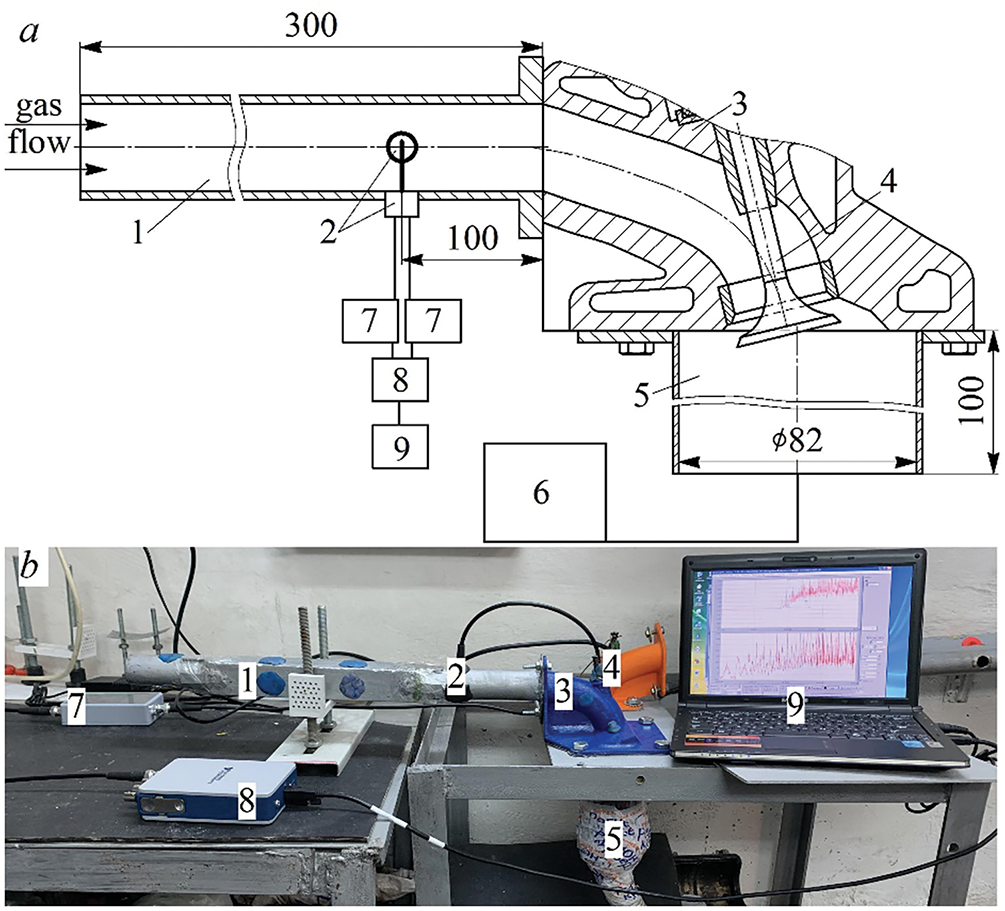
Figure 1: Diagram (a) and photograph (b) of the experimental setup: 1—inlet pipe; 2—measuring sensors; 3—channel in the CylH; 4—inlet valve; 5—cylinder; 6—pump; 7—hot-wire anemometer; 8—analog-to-digital converter; 9—laptop
The air movement in the intake system was carried out due to the vacuum in the cylinder, which was created by the pump. The cylinder diameter was 82 mm (a common car engine). The cylinder was made of ABS plastic using 3D printing. In the study, the average velocity w in the InP was from 4 to 45 m/s. The experiments covered the range of Reynolds numbers from 8500 to 96,000. This speed range covers the main operating modes of the PICE. The air temperature was 22 ± 1°C. This temperature is also the most common in the operation of the PICE of this size.
Several CylH configurations were manufactured for the study (Fig. 2). The basic cylinder head design had a valve with a round plate (the seat diameter was 32 mm) and a valve channel with a round cross-section with an internal diameter of also 32 mm (Fig. 2a). An alternative CylH design had a valve with a square plate (the seat side of the square was 28.35 mm) and a valve channel with a round cross-section with a diameter of 32 mm (Fig. 2b). The side of the square was chosen based on the equality of the cross-sectional areas with the basic valve configuration. The valve channel had a square shape only in the valve seat area with a smooth transition to a round section. The third version of the CylH design had a square valve (28.35 mm) and a square channel with a side of 32 mm (Fig. 2c). The geometry was selected based on the design capabilities and considering the preservation of the quality of the intake process.
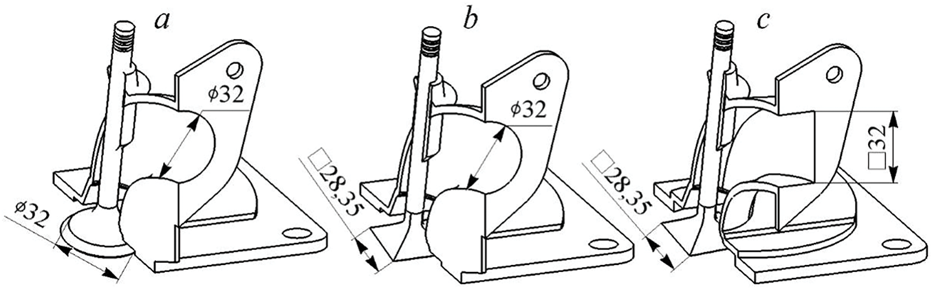
Figure 2: General view of the studied CylH designs: (a)—round valve and channel (basic configuration); (b)—square valve and round channel; (c)—square valve and square channel
The geometric dimensions of the InP and valve were selected based on the analysis of prototype engines. Most PICEs of this size (with a cylinder diameter of about 80–85 mm) have an InP with a diameter of about 32 mm.
The cylinder heads and valves were 3D printed from ABS plastic with an average roughness of 6.3 μm (technically smooth surface). The valve was in the fully open position during the tests (valve lift height was 10 mm). The cylinder head with a profiled valve channel can be manufactured using the method of casting in silicone molds for existing engines. This ensures high precision (surface roughness) and low manufacturing costs. The intake valve with a square plate and a profiled valve seat can be manufactured using 3D printing and additive technologies. This increases the cost of the parts, but ensures high precision and reliability of the design.
Instantaneous values of the flow velocity wx and the local heat transfer coefficient αх in the inlet pipe for different air flow rates through the system were determined in experiments using the thermal anemometry method. Two types of thermal thread sensors and constant temperature thermal anemometers were used for this purpose. A MiniCTA hot-wire anemometer from Dantec Dynamics (Denmark) with a sensing element (heated filament) approximately in the center of the pipe was used to determine wx. This hot-wire anemometer (MiniCTA) had the following main characteristics: maximum measurable speed up to 80 m/s; output voltage no more than 7 V; bandwidth no less than 10 kHz (for 50 m/s); sensor thread with a diameter of 5 μm and a length of 3 mm; response time no more than 1.8 ms.
In this study, the turbulence number TN was additionally determined based on the function f = wx (τ). TN was calculated as the ratio of the root-mean-square pulsation component of the velocity to the average velocity of the flow under study. The method for determining TN is described in more detail in [27,28].
The IRVIS TA-5.1 hot-wire anemometer (Russia) with an original (author’s) sensor was used to determine αх. This sensor was a fluoroplastic substrate (with a diameter of about 15 mm and a thickness of about 2 mm), on which a heated thread was placed with a slight tension. The main technical parameters of the hot-wire anemometer (IRVIS TA-5.1) were: output signal no more than 5 V; maximum flow velocity no more than 100 m/s; frequency response no less than 10 kHz; response time no less than 2.0 ms.
The method for measuring and determining the local heat transfer coefficient is described in detail in [29]. The mathematical expectation for the function f = αх (τ) was calculated for a certain period of time to obtain the average heat transfer coefficient α in the inlet pipe.
The general appearance and method of installing the sensors in the InP are shown in Fig. 3. The control section with the hot-wire anemometer sensors was in the InP at 100 mm from the window in the CylH.
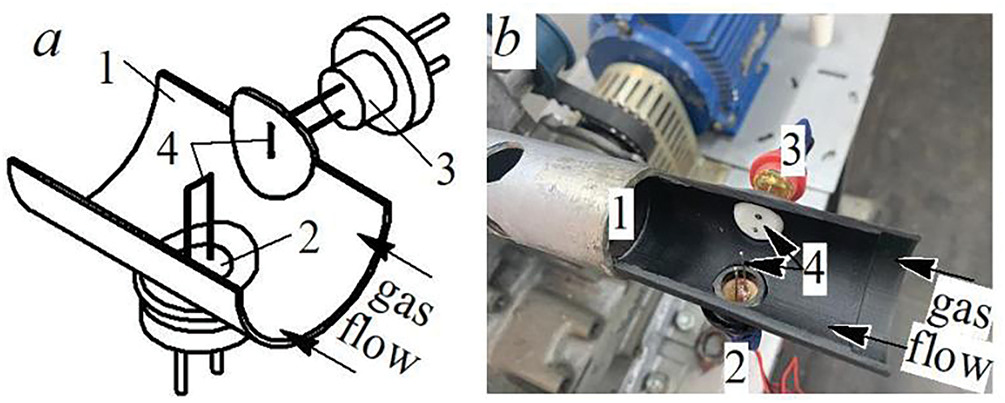
Figure 3: General view (a) and photograph (b) of the method of installing the hot-wire anemometer sensors in the inlet pipe: 1—pipe; 2—sensor for determining wx; 3—sensor for determining αх; 4—sensitive element of the sensors (thread)
The measuring system was automated, i.e., the collection and recording of experimental data was carried out in real time for several seconds (usually about 10 s) using an analog-to-digital converter and special software. The experiments were repeated at least 3–5 times to confirm the reproducibility of the results. The main physical quantities were also calculated at least 3 times for different series of experiments.
The relative uncertainty in determining the flow velocity wx in the experiments was 5.5%; the relative uncertainty in determining the αх was 10.8%.
3 Gas Dynamics and Heat Transfer of Stationary Flows in the Model of a Piston Engine Intake System
Instantaneous values of wx and αх of steady flow in the InP with different cylinder head designs for low air flow (average speed of about 13 m/s) are shown in Fig. 4.
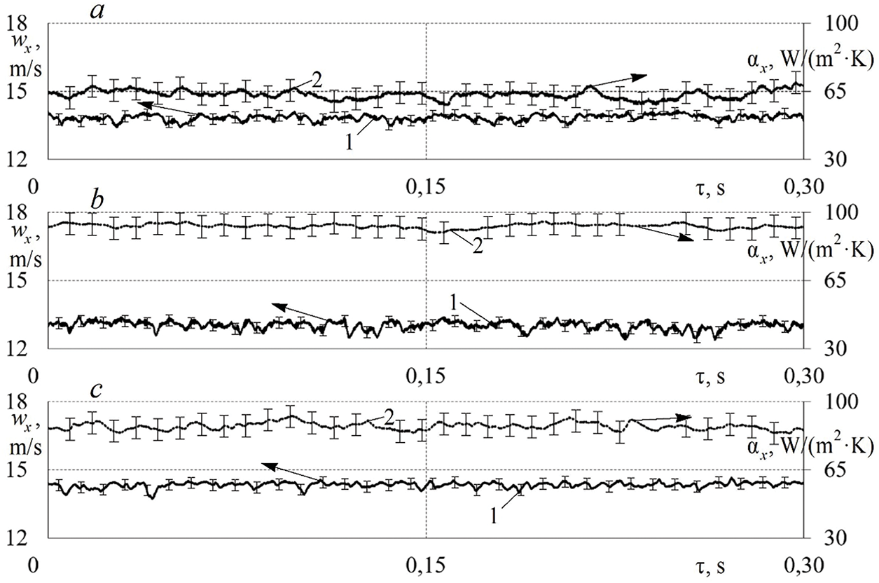
Figure 4: Change in local velocity wx (1) and local heat transfer coefficient αх (2) of stationary air flows over time τ in the intake system with different CylH designs for approximately the same average velocity in the pipe: (a)—basic design (w = 13.9 m/s); (b)—square valve (w = 13.0 m/s); (c)—square valve and channel (w = 14.3 m/s)
The use of a modernized CylH leads to minor changes in the function f = wx (τ). There are small fluctuations in wx around the average value for all the studied configurations. The use of a square valve causes a slight increase in the amplitudes of wx oscillations (Fig. 4b). Minor changes are caused by the presence of right angles in the channels and on the valve, which are external disturbing factors.
That the use of alternative CylH designs also caused minor visual changes in the function f = αх (τ). The use of a square valve and channel led to some smoothing of the function f = αх (τ), i.e., a decrease in the number of fluctuations of αх over time. There is a noticeable heat transfer intensification in the InP when using modernized cylinder heads. The average value of the heat transfer coefficient α in the InP is about 65 W/(m2·K) for the basic configuration, and α reaches 90 W/(m2·K) for the new CylH designs. Intensification of heat transfer of the flow in the modernized intake systems is associated with turbulent (disturbed) flow. From an applied point of view, the heat transfer intensification can lead to some heating of the air during the intake process, which can have a positive effect on the evaporation of fuel and improve the quality of mixing of fuel and air in the PICE cylinder. These physical phenomena are the determining factors for the completeness of combustion of the working fluid in the PICE cylinder. Therefore, the heat transfer intensification in the intake system is important for engine performance.
An increase in the average flow velocity in the pipe (up to w ≈ 32 m/s) caused a noticeable increase in the air flow velocity fluctuations (Fig. 5). The main trends in wx change in the intake system with different CylH designs are maintained with an increase in air flow (the average velocity in the pipe is about 32 m/s). The use of modernized CylH designs leads to a slight increase in air flow velocity oscillations in the InP compared to the basic configuration. The increase in oscillatory phenomena in the pipe may be associated with the formation of secondary and vortex structures in the intake system with a profiled channel and a valve in the CylH. Right angles in the pipe and on the valve remain the main factors of disturbance and restructuring of the flow.
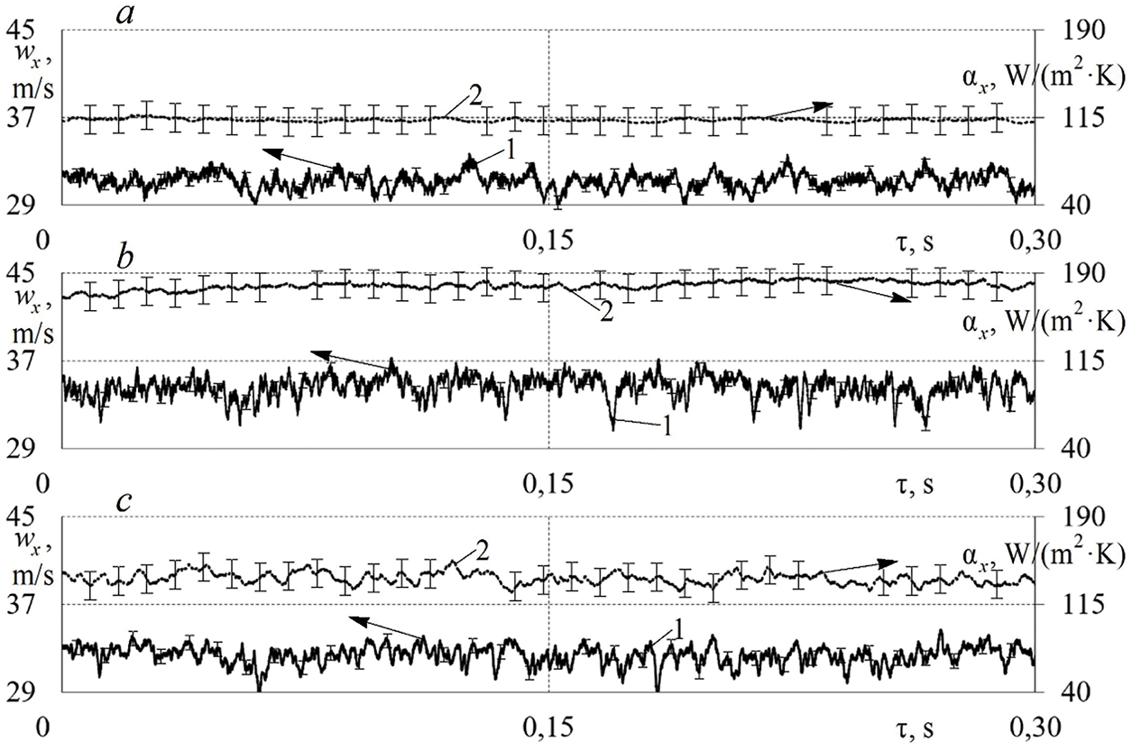
Figure 5: Change in local velocity wx (1) and local heat transfer coefficient αх (2) of stationary air flows over time τ in the intake system with different CylH designs for approximately the same average velocity in the pipe: (a)—basic design (w = 31.2 m/s); (b)—square valve (w = 34.6 m/s); (c)—square valve and channel (w = 32.4 m/s)
There is a change in the trend in the f = αх (τ) patterns when using alternative CylH designs for increased air flow through the intake system (compare Figs. 4 and 5). In this case (w ≈ 32 m/s), the use of a square valve and channel caused the formation of noticeable αх oscillations in the InP. There is also a significant intensification of heat transfer in the InP (an increase in α from 115 W/(m2·K) for the basic design to almost 200 W/(m2·K) for the upgraded configuration). Intensification of heat transfer is associated with the presence of disturbances in the flow and violation of the boundary layer. The results obtained indicate the presence of a significant influence of the CylH design on the gas-dynamic and heat exchange characteristics of stationary air flows in the intake system of the PICE.
The turbulence number TN was calculated for steady air flow in the intake pipe for three cylinder head designs (Fig. 6). TN values were calculated at least 3 times for different series of experiments to confirm the reproducibility of the results and improve accuracy. The use of modernized cylinder heads in the intake system causes an increase in TN by an average of 13.5% compared to the basic configuration (Fig. 6). The increase in TN can be explained by two factors: (1) an increase in the hydraulic resistance of the system and (2) the formation of secondary flows in the system due to the profiled channel and the plate valve. Flow disturbance, flow separation, and secondary structures were the key factors in the growth of TN values.
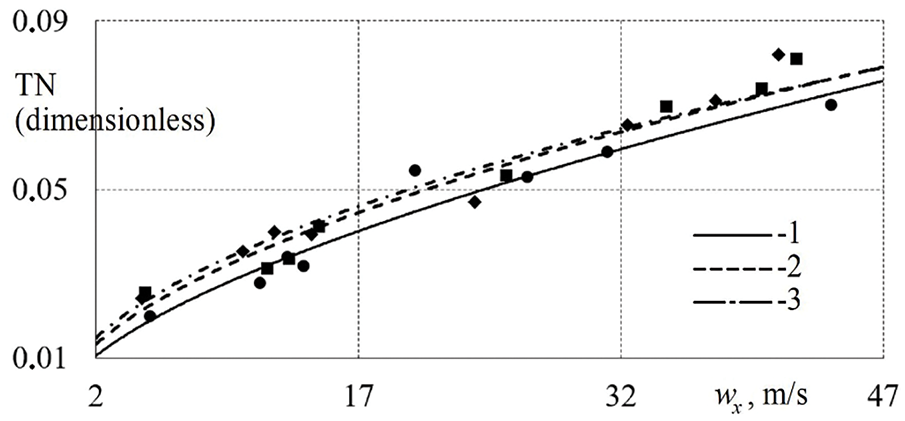
Figure 6: Dependence of the turbulence number TN in the pipe on the average air flow velocity w when using different CylH designs: 1—basic design; 2—square valve; 3—square valve and channel
Additionally, the TN values of the air flow in the engine cylinder were assessed for intake systems with different CylH designs (Fig. 7). These data are necessary to track the evolution of the gas-dynamic characteristics of the flow in the intake system and cylinder. For this purpose, the sensitive element of the hot-wire anemometer sensor was located in the center (on the axis) of the cylinder at a distance of 11.5 mm from the upper plane (under the intake valve). The experiments and calculations were also carried out at least 3 times.
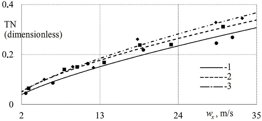
Figure 7: Dependence of the turbulence number TN of the flow in the cylinder on w when using different CylH designs: 1—basic design; 2—square valve; 3—square valve and channel
There was a tendency to increase the turbulence number TN of the flow in the cylinder when using modernized cylinder heads in the intake system (Fig. 7). In this case (in the cylinder), an increase in TN is observed on average by 19.3% for the new CylH configurations compared to the basic design. Accordingly, the turbulence of the flow in the cylinder increased somewhat compared to the InP when using new designs (the increase in TN in the pipe was 13.5%, and in the cylinder the increase in TN was 19.3%). The increase in TN is explained by the fact that the corners of the square valve are flow disturbers (flow breakdown occurs at the right angles of the valve with a square plate). Flow disturbances increase the pulsation component of the speed in the ICE cylinder.
Turbulence of the flow in the cylinder can have a positive effect in the form of improved mixing of fuel and air and obtaining a homogeneous working fluid. This can improve the quality and completeness of combustion of the fuel-air blend in the PICE. Accordingly, one can expect an improvement in the technical, economic, and environmental performance of the engine. The magnitude of the efficiency increase must be determined for each specific PICE separately.
The effect of CylH design modernization on the heat transfer intensity in the InP is shown in Fig. 8.
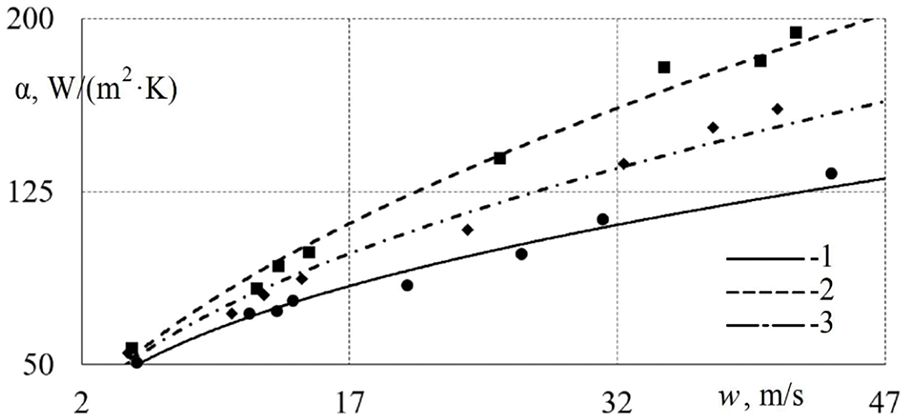
Figure 8: Dependence of the heat transfer coefficient α in the pipe on the average air flow velocity w when using different CylH designs: 1—basic design; 2—square valve; 3—square valve and channel
The use of modernized CylH designs causes an increase in the heat transfer coefficient α in the InP by an average of 15%–27% compared to the basic system configuration (Fig. 8). Thus, the use of a square intake valve in the CylH leads to an increase in α by 10%–39% compared to the basic design, and the installation of a CylH with a square valve and a square channel causes an increase in α by 7%–28%. In this case, the classical pattern is fulfilled that an increase in the turbulence number leads to a growth in the heat transfer coefficient [30]. This is usually explained by a violation of the boundary layer stability and the corresponding intensification of heat exchange between the flow and the pipe wall.
The studies were performed for single-phase flow (air flow) in this work. However, it is possible to analyze the influence of the obtained results on a potential two-phase flow (air flow with liquid fuel injection) based on literature data. Intensification of heat transfer in the intake system usually has a positive effect on the processes of evaporation, mixing, mixture formation, and combustion in piston engines [31,32]. Potentially, this can lead to an increase in specific power, a decrease in specific fuel consumption, and an improvement in the environmental friendliness of the exhaust gases of the PICEs. Improvement of the engine’s environmental performance is associated with an increase in the quality and completeness of fuel combustion [33].
The pattern associated with the heat transfer intensification in the InP in the case of using modernized cylinder heads is preserved when moving from the function α = f (w) to the dimensionless indicators Nu (Nusselt number) and Re (Reynolds number) (Fig. 9). This is due to the fact that the flow rates are low; the experiments are carried out at almost atmospheric pressure; the working medium is air (single-phase flow). Accordingly, there are no factors that could disrupt the relative values of the heat transfer level when switching to dimensionless parameters.
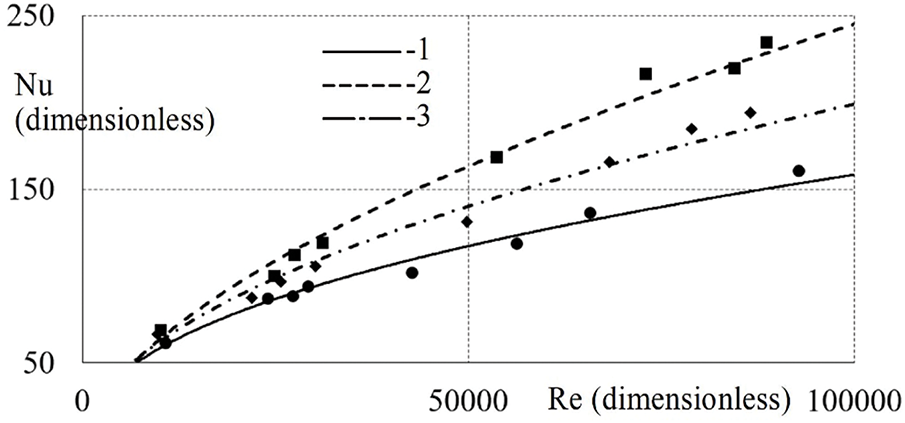
Figure 9: Dependence of the Nusselt number Nu in the pipe on the Reynolds number Re when using different CylH designs: 1—basic design; 2—square valve; 3—square valve and channel
The increase in Nu in the intake pipe is on average 15%–30% in the case of using new CylH designs compared to the basic configuration of the intake system.
The main conclusions of this study are as follows:
1. An experimental setup, instrumentation, and methodology for studying the gas dynamics and heat exchange of stationary air flows in the intake system with original CylH designs were created.
2. New experimental data on the change in wx and αх of the flow in different modifications of the intake system as applied to the PICE were obtained; the turbulence number TN was calculated for flows in the pipe and cylinder, and the heat transfer intensity in the pipe for the studied system configurations was determined.
3. The use of a square valve and a square channel in the CylH caused an increase in TN by an average of 13.5%; it was revealed that the increase in TN in the cylinder was about 19% when installing modernized CylH designs.
4. There was an intensification of heat transfer in the InP by 10%–40% when installing modernized CylH designs in the intake system;
5. The pattern of change in the heat transfer level in the InP in dimensionless form Nu = f (Re) for all studied configurations of the intake system was presented; heat transfer intensification was confirmed.
6. Applied issues of increasing the turbulence number and heat transfer intensification of stationary air flow in the intake system were discussed in relation to piston engines.
The described results relate to a single-phase, stationary air flow in a complex gas-dynamic system. Further research direction may be related to the study of proposed CylH designs for pulsating air flows (i.e., with rotating camshaft and opening/closing intake valve). Conducting tests on a working PICE with the developed intake system designs is also considered as part of the plans for new research.
Acknowledgement: Not applicable.
Funding Statement: The author received no specific funding for this study.
Availability of Data and Materials: The data that supports the findings of this study are available from the author upon reasonable request.
Ethics Approval: Not applicable.
Conflicts of Interest: The author declares no conflicts of interest to report regarding the present study.
References
1. Druzhinin AM. Piston engines of the new generation (without turbo supercharging). Ekaterinburg, Russia: Ridero; 2018. [Google Scholar]
2. Breeze P. Piston engine-based power plants. Cambridge, MA, USA: Academic Press; 2017. [Google Scholar]
3. Ahmad Harazi MF, Hairuddin AA, As’arry A, Masuri SU. Effects of different throttle opening and air intake lengths on the volumetric efficiency of SI engine using 1D simulation method. Pertanika J Sci Technol. 2024;32(4):1481–500. doi:10.47836/pjst.32.4.03. [Google Scholar] [CrossRef]
4. Hemanandh J, Ganesan S, Devaraj R, Venkatesan SP, Ramprakash G. Robust design approach for intake manifold of the 1 litre turbo charger intercooler diesel engines. Int J Ambient Energy. 2020;41(11):1214–26. doi:10.1080/01430750.2018.1507935. [Google Scholar] [CrossRef]
5. Ali Jemni M, HadjKacem S, Ammar M, Saaidia R, Brayek M, Abid MS. Variable intake manifold geometry influence on volumetric efficiency enhancement at gaseous engine starting speeds. Proc Inst Mech Eng Part E J Process Mech Eng. 2021;235(2):548–59. doi:10.1177/0954408920973129. [Google Scholar] [CrossRef]
6. Akbar Ali MH, Mohamad Razlan Z, Abu Bakar S, Eswanto E, Maruyama N, Mohamad MS, et al. Impact of intake manifold geometry on power and torque: a simulation-based study. J Adv Res Fluid Mech Therm Sci. 2025;128(1):169–80. doi:10.37934/arfmts.128.1.169180. [Google Scholar] [CrossRef]
7. Plotnikov L, Davydov D, Krasilnikov D, Shurupov V. Influence of the channel design on the heat exchange characteristics of pulsating flows in the supply system of an engine. Front Heat Mass Transf. 2024;22(5):1309–22. doi:10.32604/fhmt.2024.056680. [Google Scholar] [CrossRef]
8. Demİr Ü, Çetİnkaya O, Türkmen AC, Çelİk DDC. Experimental investigation of intake manifold design effect on diesel engine performance. Int J Automot Sci Technol. 2022;6(2):127–34. doi:10.30939/ijastech.1108430. [Google Scholar] [CrossRef]
9. Luong GH, Vo CT, Hoang DN. Impact of helical intake manifold geometries on swirl generation in cylinder of small diesel engine. Microactuators Microsens Micromech Mech Mach Sci. 2025;177(10):104–13. doi:10.1007/978-3-031-83357-1_11. [Google Scholar] [CrossRef]
10. Wang G, Yu W, Li X, Yang R. Influence of fuel injection and intake port on combustion characteristics of controllable intake swirl diesel engine. Fuel. 2020;262(8):116548. doi:10.1016/j.fuel.2019.116548. [Google Scholar] [CrossRef]
11. Velmurugan T, Durairaj S, Balaji E, Yuvaraj G. Design and CFD analysis of intake manifold with improved performance in IC engine. AIP Conf Proc. 2025;3137(1):040009. doi:10.1063/5.0263072. [Google Scholar] [CrossRef]
12. Choe SG, Choe TH, Ho IC, Mun MH, Kim IJ, Ri JH, et al. Effect of the geometrical shapes of the helical-spiral shroud intake valve on swirl generation in cylinder of diesel engine. Results Eng. 2023;18(747):101132. doi:10.1016/j.rineng.2023.101132. [Google Scholar] [CrossRef]
13. Dziubak T, Karczewski M. Experimental study of the effect of air filter pressure drop on internal combustion engine performance. Energies. 2022;15(9):3285. doi:10.3390/en15093285. [Google Scholar] [CrossRef]
14. Pranoto S, Ubaidillah, Lenggana BW, Budiana EP, Wijayanta AT. Fluid flow analysis at single and dual plenum intake manifolds to reduce pressure drops using computational approach. J Adv Res Fluid Mech Therm Sci. 2022;97(1):1–12. doi:10.37934/arfmts.97.1.112. [Google Scholar] [CrossRef]
15. Pahmi A, Hisyam Basri M, Mustaffa ME, Yaakob Y, Sharudin H, Ismail NI, et al. Intake pressure and brake mean effective pressure analysis on various intake manifold design. J Phys Conf Ser. 2019;1349(1):012080. doi:10.1088/1742-6596/1349/1/012080. [Google Scholar] [CrossRef]
16. Borisov I, Tuzharov K, Iliev S. CFD analysis on the effects of the intake manifold geometry on volumetric efficiency. AIP Conf Proc. 2024;3294(1):020017. doi:10.1063/5.0255591. [Google Scholar] [CrossRef]
17. Popov IA, Zhukova YV, Gureev VM, Chornyi AD, Popov IAJr. Numerical simulation of air intake of aviation piston engines. Russ Aeronaut. 2024;67(3):625–33. doi:10.3103/S1068799824030188. [Google Scholar] [CrossRef]
18. Han X, Liu D, Liu L, Fu S. Research on scavenging flow dynamics of marine two-stroke engines with a CFD-derived quasi-dimensional model. Int J Engine Res. 2024;25(8):1611–22. doi:10.1177/14680874241240193. [Google Scholar] [CrossRef]
19. Saaidia R, Ghriss O, Köten H, Alquraish M, Bouabidi M, El Haj Assad A, et al. Effects of intake manifold geometry in H2 & CNG fueled engine combustion. J Therm Eng. 2024;10(1):153–63. doi:10.18186/thermal.1429746. [Google Scholar] [CrossRef]
20. Zhang J, Wang S, Wang Z, Xie Z, Chang Y. Investigation of intake and exhaust performance in heavy-duty diesel engines with variable Miller cycle. Appl Therm Eng. 2025;265(2):125547. doi:10.1016/j.applthermaleng.2025.125547. [Google Scholar] [CrossRef]
21. Raja K, Selvam AJ. Experimental investigation of four stroke single cylinder SI engine by modified intake manifold by using computational fluid dynamics. Int J Ambient Energy. 2022;43(1):229–36. doi:10.1080/01430750.2019.1630310. [Google Scholar] [CrossRef]
22. Paranjape S, Thakur S, Emran A, Wagh S, Sharma V. Intake and exhaust system optimization of a single cylinder engine using 1D simulation approach. In: SAE Technical Paper Series. Pune, India: SAE International; 2024. doi:10.4271/2024-26-0212. [Google Scholar] [CrossRef]
23. Galambos S, Nikolic N, Ruzic D, Doric J. An approach to computational fluid dynamic air-flow simulation in the internal combustion engine intake manifold. Therm Sci. 2020;24(1 Part A):127–36. doi:10.2298/tsci180707063g. [Google Scholar] [CrossRef]
24. Cebula A, Kowalczyk S, Świątek P. A numerical analysis of the air flow through the IC engine intake manifold. Prog Comput Fluid Dyn Int J. 2019;19(1):63. doi:10.1504/pcfd.2019.10018846. [Google Scholar] [CrossRef]
25. Kim YJ, Yoon AS, Lee CE. Validation of CFD analysis on flow and combustion characteristics for a GP3 rotary engine. Energies. 2025;18(4):758. doi:10.3390/en18040758. [Google Scholar] [CrossRef]
26. Wang CD, Wei MX, Li BL, Xu ZX, Wei YY. Study and analysis of intake and exhaust system of electric turbocharged aviation piston engine. J Aerosp Power. 2025;40(2):171–9. doi:10.13224/j.cnki.jasp.20230245. [Google Scholar] [CrossRef]
27. Plotnikov L. The influence of longitudinal duct profiling on unsteady gas dynamics and the heat transfer of pulsating gas flows in the outlet system of reciprocating-engine. Therm Sci Eng Prog. 2024;55(17):102977. doi:10.1016/j.tsep.2024.102977. [Google Scholar] [CrossRef]
28. Plotnikov L. Gas dynamics and heat exchange of stationary and pulsating air flows during cylinder filling process through different configurations of the cylinder head channel (applicable to piston engines). Int J Heat Mass Transf. 2024;233(1):126041. doi:10.1016/j.ijheatmasstransfer.2024.126041. [Google Scholar] [CrossRef]
29. Plotnikov L, Plotnikov I, Osipov L, Slednev V, Shurupov V. An indirect method for determining the local heat transfer coefficient of gas flows in pipelines. Sensors. 2022;22(17):6395. doi:10.3390/s22176395. [Google Scholar] [PubMed] [CrossRef]
30. Terekhov VI. Heat transfer in highly turbulent separated flows: a review. Energies. 2021;14(4):1005. doi:10.3390/en14041005. [Google Scholar] [CrossRef]
31. Arabkhalaj A, Verwey C, Birouk M. Experimental study of butanol droplet combustion in a turbulent, elevated-pressure environment. Combust Flame. 2025;276:114150. doi:10.1016/j.combustflame.2025.114150. [Google Scholar] [CrossRef]
32. Shah F, Fall I, Zhang D. Breakage and coalescence mechanisms in multiphase flow comprehensive PBM-CFD review with turbulence modelling insights for gas-liquid system. Int Commun Heat Mass Transf. 2025;165(1):109093. doi:10.1016/j.icheatmasstransfer.2025.109093. [Google Scholar] [CrossRef]
33. Sun P, Cheng X, Yang S, Ruan E, Zhao H, Liu Y, et al. Artificial neural network models for forecasting the combustion and emission characteristics of ethanol/gasoline DFSI engines with combined injection strategy. Case Stud Therm Eng. 2024;54(5):104007. doi:10.1016/j.csite.2024.104007. [Google Scholar] [CrossRef]
Cite This Article
 Copyright © 2025 The Author(s). Published by Tech Science Press.
This work is licensed under a Creative Commons Attribution 4.0 International License , which permits unrestricted use, distribution, and reproduction in any medium, provided the original work is properly cited.
 Downloads
 Citation Tools