
 Submit a Paper
 Propose a Special lssue
 Open Access
ARTICLE

Simulation of Temperature Field in Oil-Based Drill Cuttings Pyrolysis Furnace for Shale Gas
School of Mechanical Engineering, Sichuan University of Science and Engineering, Yibin, 644000, China
* Corresponding Author: Guangwei Bai. Email:
(This article belongs to the Special Issue: Heat Transfer Analysis and Optimization in Energy Systems)
Frontiers in Heat and Mass Transfer 2025, 23(6), 1847-1864. https://doi.org/10.32604/fhmt.2025.070378
Received 15 July 2025; Accepted 19 September 2025; Issue published 31 December 2025
 View Full Text
 Download PDF
Abstract
To address the issue of uneven temperature distribution in shale gas oil-based drill cuttings pyrolysis furnaces, a numerical model was developed using Fluent software. The effects of nitrogen flow rate, heating tube spacing, and furnace dimensions on the internal temperature field were thoroughly analyzed from a mechanistic perspective. The results indicated that non-uniform radiation from the heating tubes and flow disturbances induced by the nitrogen stream were the primary causes of localized heat concentration. Under no-load conditions, the maximum deviation between simulated and on-site measured temperatures was 1.5%, validating the model’s accuracy. Furthermore, this study investigated the trade-offs between temperature uniformity, energy consumption, and construction costs. The findings provide a crucial design basis and a reliable simulation platform for developing and optimizing pyrolysis equipment.Keywords
Shale gas is a significant unconventional energy resource with extensive global reserves, estimated at approximately 7795 trillion cubic feet (TCF) of recoverable natural gas [1,2]. Its exploitation can substantially alleviate energy demand pressures. Oil-based drilling fluids (OBDF) are widely used in unconventional oil and gas exploration, such as shale gas development, due to their superior inhibition, lubrication, stability, contamination resistance, and ability to prevent mud hydration [3–5]. However, the drilling process generates oil-based drill cuttings (OBDC), which contain hazardous substances such as base oils, heavy metals, and organic compounds [6–8]. Improper disposal poses significant environmental risks, including water contamination and harm to flora, fauna, and human health [9]. Consequently, OBDC are classified as hazardous waste (HW08) under China’s “National Hazardous Waste List” (2025 Edition) and are subject to stringent regulation.
Various methods exist for OBDC treatment and resource recovery, including microwave heating [10], solvent extraction [11], microbial degradation [12], pyrolysis thermal desorption [13–15], Chemical cleaning [16], Ultrasound-Flotation- Advanced Oxidation [17], Agricultural cultivation method [18] and Burning method [19]. However, many of these technologies face limitations—such as low processing efficiency, high complexity and cost, an inability to recover base oil, and potential environmental risks—which have hindered their widespread adoption.
Pyrolysis offers advantages including short processing cycles, rapid treatment, broad applicability, low environmental sensitivity, and energy recovery potential, leading to its prevalent use in the Southern Sichuan Basin [20].
Pyrolysis process parameters critically influence OBDC treatment efficacy. Pyrolysis regimes are categorized as low-temperature (LTTD), medium-temperature, or high-temperature [21,22]. Common reactor designs include screw conveyors [23], rotary kilns [24], Coiled-tube pyrolysis furnace [25], Electromagnetic induction pyrolysis furnace [26], Fluidized bed pyrolysis furnace [27] and pyrolysis furnaces. Gao et al. [28] conducted a simulation of the thermal decomposition process of oil sludge in a rotary kiln, and found that at a temperature of 1400 K, the yield of gaseous products (CH4, C2H4, C2H6, CO and H2) reached its maximum. Zhao et al. [29] conducted a numerical simulation of the forced convective heat transfer within the spiral heat exchanger and obtained the correlation of the heat transfer coefficient for oil-based drill cuttings. Nguyen and San [30] found that the material of the heat exchanger’s wall surface can reduce the influence of thermal conductivity on the heat exchange efficiency.
In the southern Sichuan Basin, pyrolysis technology has become the mainstream treatment method due to its high crude oil recovery rate and low secondary pollution levels. The daily processing capacity of industrial-grade pyrolysis furnaces can reach 230 t. However, an operational issue persists: uneven temperature distribution inside the furnace. This problem directly reduces the oil vapor recovery rate (by up to 15%) and causes local overheating, leading to increased energy consumption and shortened equipment lifespan. The temperature unevenness inside the pyrolysis furnace is not determined by a single factor but results from multiple interrelated factors, which can be summarized as follows:
(1) Unevenness of radiation from the heating element: The thermal distillation furnace type pyrolysis furnace adopts W-shaped gas heating tubes (Fig. 1). Wang et al. [31] improved the working efficiency of the reheating furnace by changing the distribution position of the burners using the finite volume method (FVM). Garcia et al. [32] improved the heating characteristics of the step-beam type reheating furnace for steel by changing the position of the burner.
(2) Disturbance of the airflow (nitrogen gas): Nitrogen is a necessary gas for maintaining an oxygen-deficient environment, but its flow rate can significantly disrupt temperature stability. Ding et al. [33] increased the inlet gas flow velocity of the sulfurization reactor, thereby enhancing the heat transfer efficiency. Dhamodaran et al. [34] concluded that the flow rate of the inlet gas would affect the temperature field within the channel.
(3) The scale effect of the size of the pyrolysis furnace: Barroso et al. [35] increased the energy utilization rate of the pyrolysis furnace by increasing the ratio of the height to the diameter of the furnace. Wang and Liu [36] enhanced the heat exchange process of the oil-based drill cuttings by increasing the length of the pyrolysis furnace.
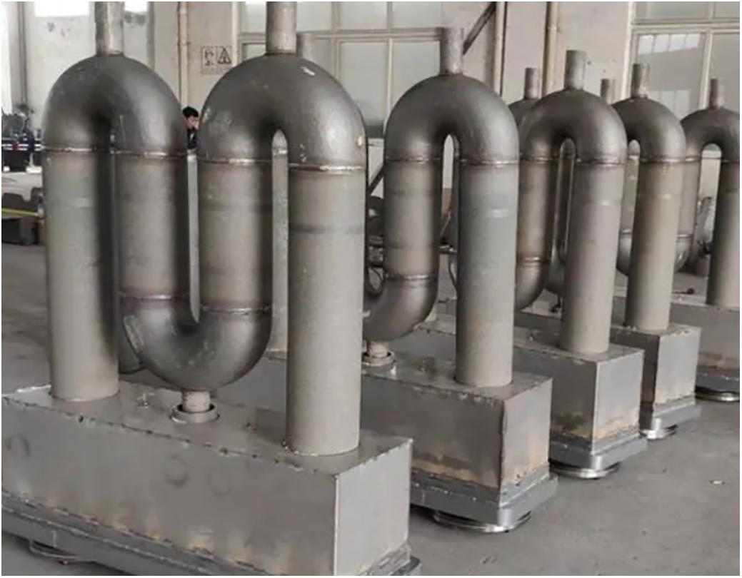
Figure 1: Schematic of the W-shaped gas heating tube
Therefore, this study adopts a simplified physical model of the pyrolysis furnace and uses Fluent software to simulate the effects of furnace length, width, heat source position, and nitrogen inlet velocity on the internal temperature field, providing a reference for developing an efficient and energy-saving pyrolysis desorption device.
Due to the extremely complex nature of the oil-based drill cuttings pyrolysis process, which involves multiphase flow, heat transfer, and chemical reactions, these factors interact with each other to form an internal temperature gradient field. To fundamentally clarify the influence of the furnace structure and flow field on the temperature distribution, this paper established a model under no-load conditions. This method can separate the key geometric and operational parameters (nitrogen flow rate, heating pipe spacing) from the complex effects of raw material pyrolysis, providing a clear and reliable basis for optimizing the basic design of the oil-based drill cuttings pyrolysis furnace. The data obtained from this simulation will provide the necessary foundation for subsequent coupled studies based on reaction models.
Due to the symmetrical spatial geometry and physical structure of the cracking equipment, in order to ensure the rationality of the calculation cycle and reduce the verification cost, this model simplifies the on-site test model of the cracking furnace (Fig. 2a) and the control panel (Fig. 2b), and converts it into a two-dimensional model. Now, we use Ansys Fluent for simulation to simulate the temperature field distribution during the equipment operation, in order to save a lot of costs and time. Since Fluent has powerful fluid calculation capabilities, it can accurately calculate various data such as temperature, pressure, heat, and mass, and can better control variables for research and calculation, thereby studying the influence of various factors on the temperature field.
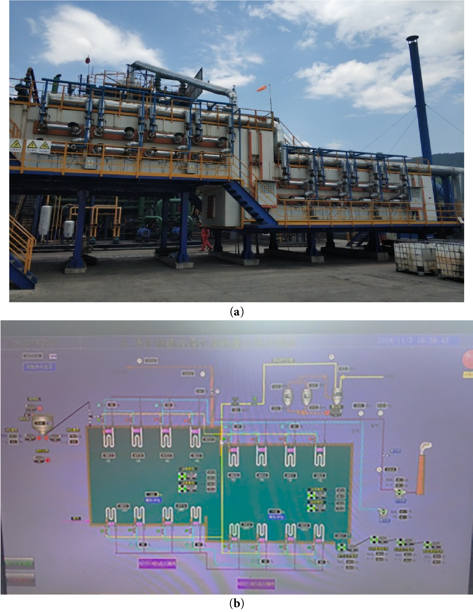
Figure 2: (a) Oil-based drill cuttings field test model; (b) Ontrol interface of the on-site pyrolysis treatment equipment
Mix the air and gas, and then send them into the gas heating tube for combustion. The generated heat continuously provides energy to the tube wall. The tube wall transfers the heat to the oil-based drill chips in the furnace through convection and radiation.
To maintain non-oxidative conditions during pyrolysis and prevent combustion in high-temperature zones, nitrogen was employed as an inert carrier gas in both numerical simulations and experiments. The use of nitrogen not only suppresses oxidation reactions—ensuring consistent pyrolysis kinetics—but also promotes rapid transport of oil vapors to the condensation and recovery system, thereby minimizing secondary cracking and enhancing oil recovery. Throughout the process, nitrogen was introduced into the furnace at a temperature of 500 K, with an inlet velocity ranging between 0.088 and 0.238 m/s.
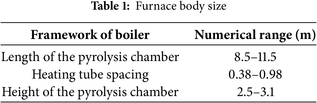
The main parameter ranges of the pyrolysis furnace as specified by the on-site layout are shown in Table 1, including the length L, width Z and spacing D of the heating tubes of the pyrolysis chamber. The interior dimensions of the furnace are large. The insulation layer of the furnace wall is made of a refractory layer (refractory bricks) as the inner lining, supplemented by a heat insulation layer (silica fume) for heat preservation. The conveyor belt is made of steel plates. The W-shaped gas heating tube is made of high chromium-nickel austenitic stainless steel (20cr20Ni).
The physical properties of the solid materials related to the model inside the furnace are shown in Table 2.
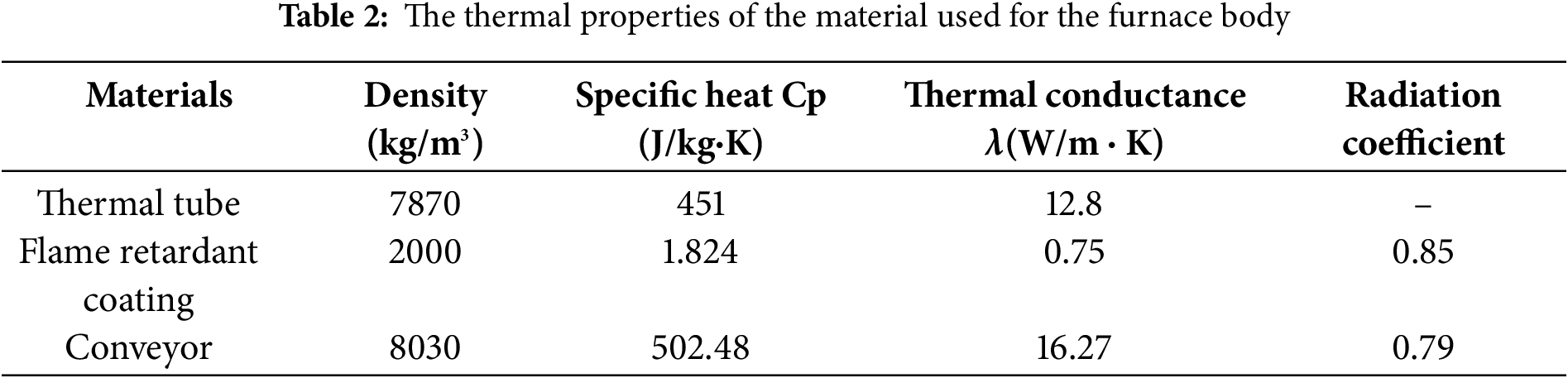
To enhance the fluid-solid coupling effect in the simulation, the W-shaped gas heating tubes were simplified to equivalent-diameter heating rods. The insulation layer was modeled as a refractory material and the conveyor belt as a solid steel plate.
The pyrolysis furnace constitutes the core equipment of the reaction system. Sixteen radiant tubes (arranged in four sets) are installed, evenly distributed above and below the conveyor belt to ensure uniform heating of the OBDC (Fig. 3). The furnace transports OBDC via a steel plate conveyor belt driven by an external motor. Radiant energy from the upper and lower heating tubes acts upon the OBDC surface, effecting pyrolysis.
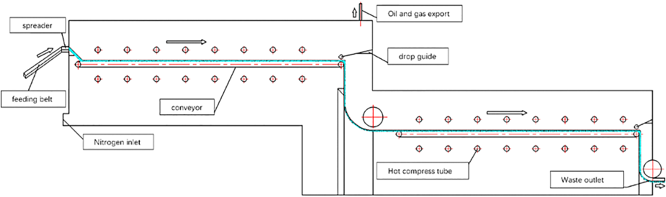
Figure 3: Schematic diagram of pyrolysis process
The industrial-scale pyrolysis furnace is large and utilizes gas combustion as the heat source. W-shaped gas heating radiant tubes provide energy to the furnace interior via radiation. Gas and air are injected through nozzles, ignited by burners, and combust internally, transferring heat to the tube walls. Crucially, the flue gas within the heating tubes does not contact the pyrolysis vapors, preserving recovered oil quality and preventing direct interaction between combustion products and OBDC.
The gas flow pattern within the furnace is illustrated in Fig. 4. Nitrogen (inert gas) is continuously introduced throughout the process for two primary purposes: (1) To purge excess air, maintaining an oxygen-deficient environment essential for safe operation; (2) To maintain stable pressure within the sealed furnace while pyrolysis vapors are extracted for recovery. During pyrolysis, OBDC release water vapor, oil vapors, and other gases, most of which flow towards the exhaust port leading to the condensation tower.
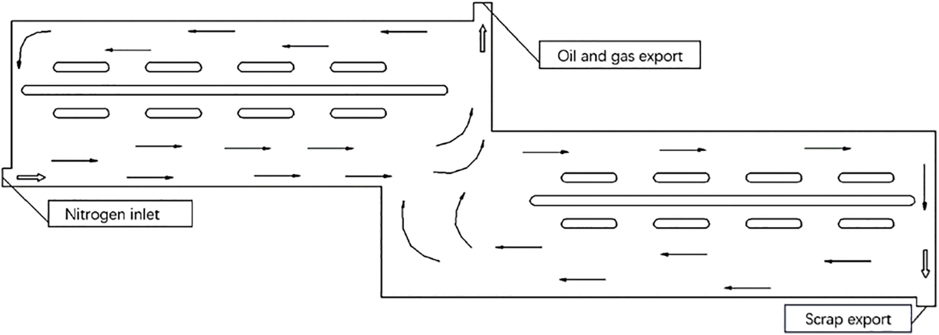
Figure 4: Schematic diagram of gas flow in the furnace
This model focuses on the basic heat transfer mechanisms (conduction, convection and radiation) within the furnace and the gas flow. It provides a robust platform for analyzing the influence of structural and operational parameters on the temperature field before introducing the additional complexity of reaction materials.
Inside the pyrolysis furnace, heat conduction occurs within the insulation layer of the furnace wall and in the solid area of the conveyor belt; convection occurs on the external and internal surfaces of the furnace chamber, the surface of the conveyor belt, and the surface of the gas heating pipe; radiative heat transfer occurs on the internal surfaces of the furnace chamber, the surface of the oil-based drill cuttings, the surface of the heating pipe, and the surface of the conveyor belt. The heat transfer process is shown in Fig. 5.
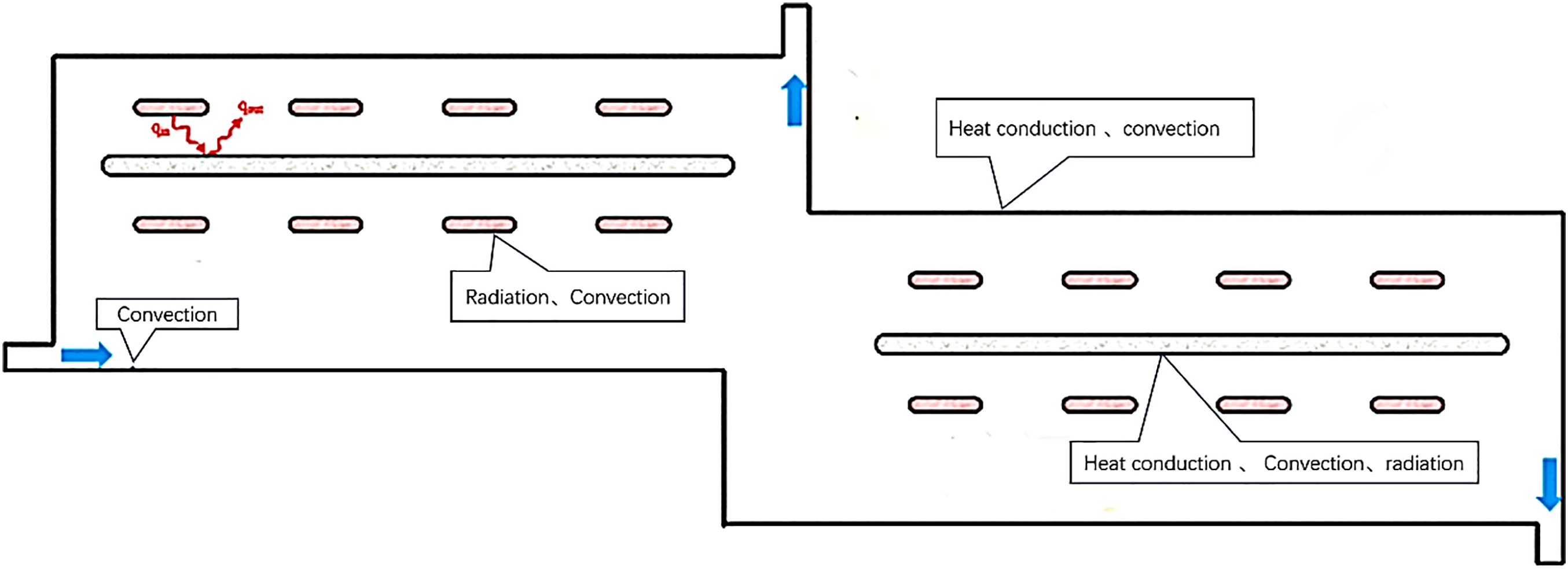
Figure 5: Schematic diagram of energy transfer process in pyrolysis furnace
① Heat conduction
The interior of the furnace chamber is wrapped by an insulating layer, and heat conduction mainly occurs within the solid material. The energy equation of transient heat conduction:
where,
• Flow and convection
Convective heat transfer occurs inside the thermal distillation furnace. Nitrogen is introduced from the gas inlet and circulates within the furnace, being discharged at the oil and gas outlet. During the convective process, a portion of the heat is usually carried away. To solve the temperature carried away in this part, it is often necessary to analyze the mass conservation control equation (continuity equation), momentum conservation control equation (N-S equation), and energy conservation control equation of the furnace gas.
Mass conservation control equation:
Momentum conservation control equation:
Among them,
Energy conservation control equation:
Among them,
The heat generated by the solid wall surface will be affected by convection. The furnace temperature is calculated by using the radiation transfer equation to obtain the absorption and emissivity of the furnace gas.
• Radiative transfer equation
The radiative heat transfer model will affect the reliability of the numerical simulation results of heat transfer. Five radiation models are presented in FLUENT: DTRM model, P1 model, Rossland model, Surface-to-Surface radiation model and Discrete Coordinate Model (DOM). The DO model is used in this simulation of the radiative heat transfer process in the tubular heating furnace. The DO model algorithm is applicable to all optical depth problems, and its transport equation is:
Among them,
For the DO model, the wall temperature is calculated based on the following equation, and the input radiant heat flow is:
Output radiant heat flow:
Among them,
When setting up the pyrolysis furnace model, the energy equation is activated first. The turbulence model is set to the K-epsilon model, the radiation option is enabled, and the Do model is selected. The solution method is set to “Coupled”, and the relaxation factors for momentum and pressure are set to 0.75. All other default values remain unchanged. The initial velocity (v) of nitrogen is set at 0.088, 0.138, 0.188, and 0.238 m/s. The entry temperature of the nitrogen is set at 500 K, while the other initial temperatures are set at 300 K.
In order to verify whether the number of grids has an impact on the calculation results, the length, width and distance between the heating tubes of the pyrolysis furnace are set to 10.5, 2.9 and 0.58 m, respectively, and the inlet speed of nitrogen is set to 0.188 m/s. The result of the independence of grid quantity is shown in Fig. 6. The grid quantity increased from 106,982 to 195,744, with a change rate of 82%. The internal average temperature fluctuated between T = 591.3 and 595.4 K. Therefore, the change in grid quantity has no effect on the temperature of the pyrolysis furnace. Therefore, in this article, the number of grids is set to 106,982.
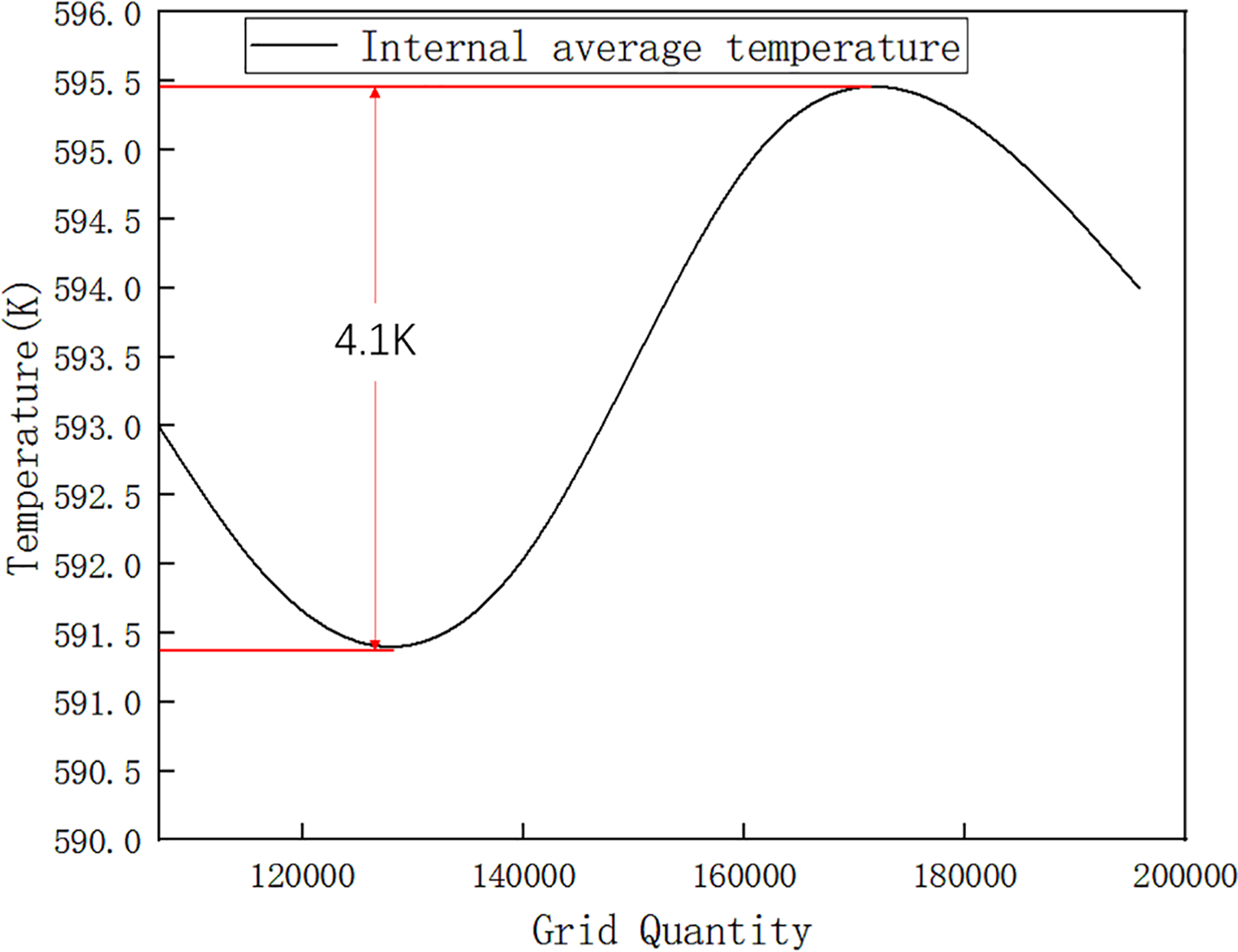
Figure 6: Relationship between the number of grids and the average temperature of the pyrolysis chamber
3.1 Pyrolysis Furnace No-Load Verification
Fig. 7a,b presents the temperature contour and the conveyor belt surface temperature profile, respectively, for a furnace with dimensions L = 10.5 m, Z = 2.9 m, D = 0.58 m, and a nitrogen inlet velocity V = 0.138 m/s under no-load conditions. Analysis of the temperature field reveals lower temperatures (light blue) near the conveyor belt. Higher temperatures were observed near the walls, with heat concentrated primarily along the left and bottom sections. This distribution arises from two factors: (1) Heat radiated from the tubes is absorbed effectively by the conveyor belt due to its high thermal conductivity. (2) The well-insulated furnace walls minimize heat loss, causing heat to accumulate within the chamber. The simulated temperatures at three monitoring points near the furnace outlet were compared with field measurements (Table 3). The deviations were 6.9, 9.6, and 4.3 K, corresponding to relative errors of 1.1%, 1.5%, and 0.7%, respectively. The high consistency between simulation and measurement under no-load conditions verified the accuracy of our heat transfer model and solver settings, laying a reliable foundation for subsequent parametric studies.
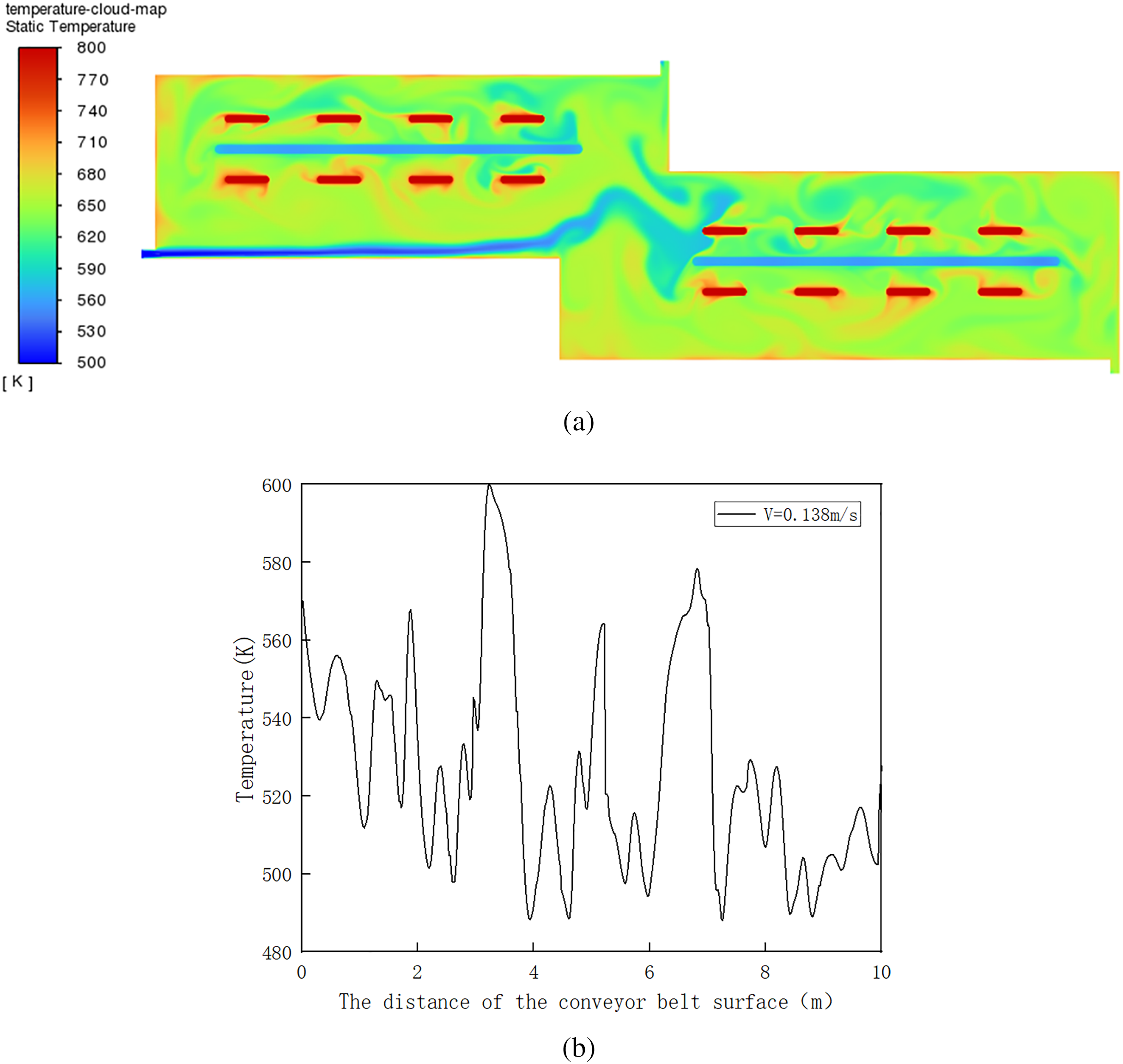
Figure 7: (a) Simulation cloud map of the pyrolysis furnace under no-load condition; (b) Temperature curve of the conveyor belt surface
3.2 The Influence of Nitrogen Gas Velocity on the Temperature Field
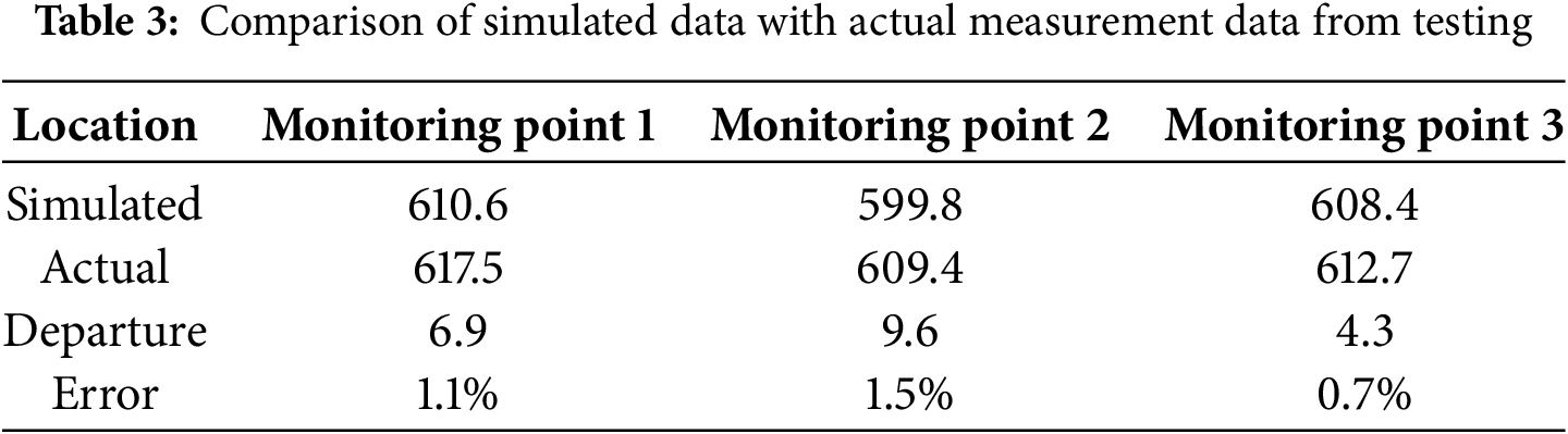
Fig. 8a,b displays the internal temperature contours and the conveyor belt surface temperature profiles, respectively, at different nitrogen inlet velocities. At velocities V = 0.088–0.138 m/s, heat remains concentrated near the left sidewall and furnace bottom. The internal temperature distribution is extremely sensitive to the inlet speed of nitrogen. When the nitrogen flow rate is too low (0.088–0.138 m/s), the kinetic energy of the flow is insufficient, which makes it impossible to effectively disrupt the convection and thermal stratification caused by heat radiation. As a result, the heat accumulates in the upper left part of the furnace, forming a local high temperature area. When the nitrogen velocity was increased to 0.188 m/s, the enhanced convection facilitated the intense mixing of the fluid, transferring thermal energy from the high-temperature regions (near the walls and the pipe) to the core area, thereby achieving the homogenization of the temperature field. However, an excessively high nitrogen flow rate (0.238 m/s) would result in a significant cooling effect. This is because a large amount of incoming cold nitrogen (with a temperature of 500 K) would absorb a considerable amount of heat to raise its own temperature, thereby reducing the average temperature of the entire furnace and increasing energy consumption. This non-linear effect indicates the existence of an optimal speed that can both ensure the efficiency of the mixture and also take into account the efficiency of heat energy utilization.
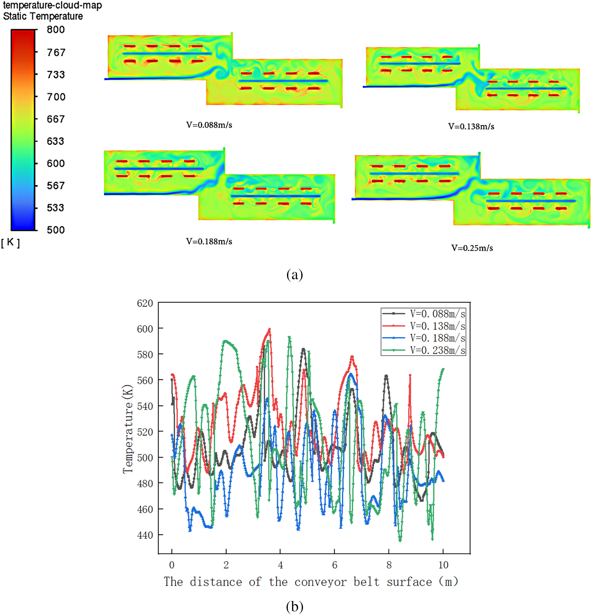
Figure 8: (a) Temperature cloud map of the pyrolysis chamber under different nitrogen flow rates; (b) Temperature curve of the conveyor belt surface
3.3 The Influence of Heating Tube Spacing on the Temperature Field
Fig. 9 presents the internal temperature contours and corresponding curves for the pyrolysis furnace under different heating tube spacings (D). When the heating pipe spacing is between D = 0.38 and 0.78 m, there is no obvious temperature concentration phenomenon inside the furnace. As the heating pipe spacing increases to D = 0.98 m, the heat mainly concentrates on the left side of the furnace wall. The spacing (D) of the heating tubes directly determines the distribution density of the radiant heat source. A too small spacing (D = 0.38 m), although it can ensure good temperature uniformity, will increase the manufacturing cost and may cause local overheating, thereby shortening the service life of the heating tubes. Appropriate increase in spacing (D = 0.78 m) can achieve a balance between uniformity and economic feasibility. On the contrary, if the spacing is too large (0.98 m), due to the decrease in heat flux, the temperature in the area far from the heat source will be too low. There will be a significant temperature gradient. The heat is mainly concentrated near the heat source, which indicates that there is a critical distance for the heating tube spacing. Beyond this distance, the temperature uniformity will deteriorate.
Figure 9: (a) Temperature maps of the pyrolysis chambers with different spacing of heating tubes. (b) Temperature curve of the conveyor belt surface
3.4 The Influence of the Length of the Pyrolysis Furnace on the Temperature Field
Fig. 10 shows the internal temperature maps and curves of the pyrolysis furnace at different lengths. When the length of the pyrolysis furnace L is 8.5 or 9.5 m, the heat is concentrated below and to the left of the furnace wall. The length of the pyrolysis furnace has a significant scale effect on the uniformity of the temperature field. The smaller size will enhance the influence of the boundary conditions at the inlet and outlet, making the temperature field more susceptible to local disturbances (such as the inlet speed of nitrogen). Increasing the size will provide a larger space for heat exchange and fluid mixing, which will weaken these boundary effects and result in a more stable and uniform temperature distribution in the central area. However, this stability comes at the cost of increased manufacturing costs, heat loss area, and higher energy consumption, reflecting the trade-off between performance and cost.
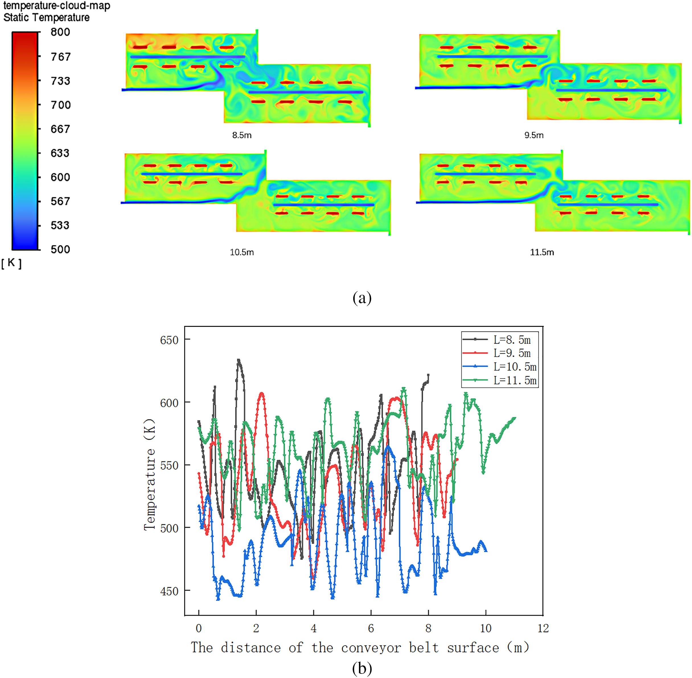
Figure 10: (a) Temperature maps of different lengths of the pyrolysis chambers in the pyrolysis furnace; (b) Temperature curve of the conveyor belt surface
3.5 The Influence of the Height of the Pyrolysis Furnace on the Temperature Field
Fig. 11 shows the internal temperature maps and curves of the pyrolysis furnace at different widths. When the height of the pyrolysis furnace H is 2.5–2.7 m, the heat is mainly concentrated in the upper left part of the wall surface. As the height increases, the concentration of heat decreases. Because, a smaller size will enhance the influence of the inlet and outlet boundary conditions, while an increased size will provide a larger space for heat exchange and fluid mixing, which will weaken these boundary effects and result in a more stable and uniform temperature distribution in the central area.
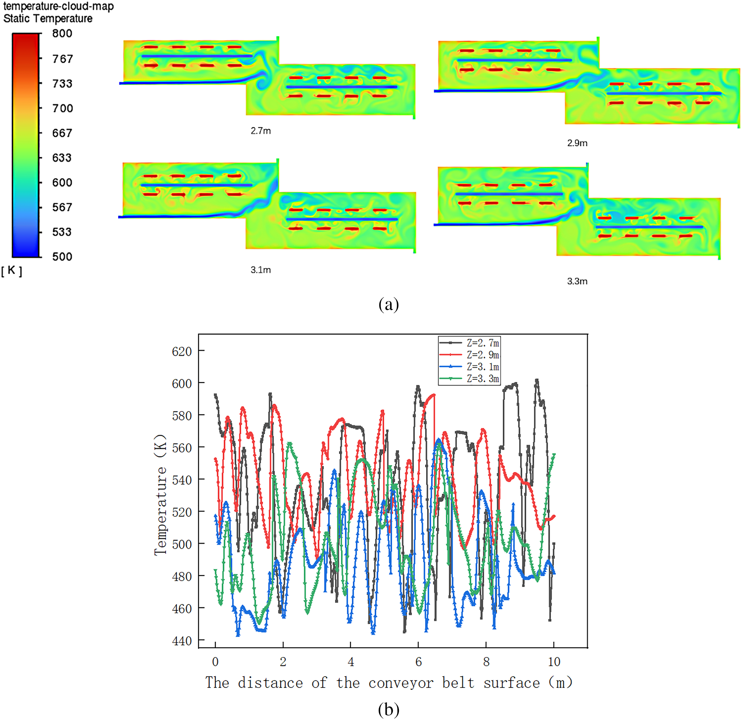
Figure 11: (a) Temperature distribution map of the internal environment of the pyrolysis furnace at different heights; (b) Temperature curve of the conveyor belt surface
3.6 Parameter Interaction and Discussion
The optimization of the pyrolysis furnace is a multi-objective problem involving multiple trade-offs among temperature uniformity, energy consumption and investment cost. Based on the above parameters, the impacts of each key factor are summarized as follows:
1. The influence of nitrogen flow rate (V) on temperature uniformity exhibits a non-linear characteristic: When the value is lower than this, heat will accumulate; when it is higher than this, the cooling effect will dominate, and both will lead to a deterioration in uniformity.
2. The spacing of heating tubes (D) is a key structural parameter that affects the construction cost and economy. Increasing the spacing can reduce costs, but once it exceeds the critical value (approximately 0.98 m), the temperature uniformity will significantly deteriorate due to the sparse distribution of heat sources. Set it at approximately 0.78 m, and this will ensure good temperature uniformity while achieving the best cost-effectiveness.
3. The length (L) of the pyrolysis furnace is the most effective structural parameter for improving temperature uniformity. Increasing the length can significantly enhance the temperature stability. However, this is also accompanied by a significant increase in equipment scale, energy consumption and capital investment. Therefore, a careful assessment needs to be made between performance and cost. The optimized length determined in this study is 10.5 m.
4. The increase in the height (H) of the pyrolysis furnace also helps to improve the temperature uniformity. However, the improvement effect is relatively limited compared to the length, and it will also increase energy consumption and construction costs. The optimization process needs to take into account the diminishing marginal returns effect. The optimal height determined in this study is 2.9 m.
In conclusion, the optimized configuration recommended by this study (V = 0.188 m/s, D = 0.78 m, L = 10.5 m, H = 2.9 m) represents a balanced solution under multiple constraints. Adjusting the nitrogen flow rate (V) and the distance between the heating tubes (D) is the most effective way to optimize without changing the main structure. The optimization of the furnace size (L, H) provides a crucial basis for the scaling-up design of industrial equipment.
(1) The temperature non-uniformity observed within the oil-based drill cuttings pyrolysis furnace is primarily attributable to the non-uniform radiative emission from the W-shaped gas heating tubes and the flow disturbances induced by the internal nitrogen stream. These factors, in conjunction with the substantial physical dimensions of the industrial-scale apparatus, complicate the attainment of consistent localized temperature regulation. Consequently, thermal energy accumulates preferentially in specific zones, thereby giving rise to an uneven overall temperature distribution throughout the furnace chamber.
(2) The pyrolysis device was simplified to a two-dimensional model, and the physical model of the pyrolysis chamber was established. The transient mode was selected for solving. The Laminar model was chosen for flow, and the DO model for radiation. The solution method was Coupled, with momentum and pressure relaxation factors set to 0.75. In the grid independence test, the length, width, and heating tube spacing of the pyrolysis furnace were set to 10.5, 2.9, and 0.58 m, respectively, with a nitrogen inlet velocity of 0.188 m/s. The grid count increased from 106,982 to 195,744 (82% change), but the average internal temperature fluctuated only between 591.3 and 595.4 K, indicating that grid number changes have no significant effect on the pyrolysis furnace temperature.
(3) Simulation of on-site data revealed that heat was mainly concentrated on the left and lower wall surfaces. Comparison with on-site measured temperatures showed a maximum error of 1.5%, confirming that the Fluent simulation accurately reflects the actual situation. Nitrogen inlet velocity significantly affects the internal temperature. Low nitrogen velocity causes heat concentration on the left and bottom of the furnace wall. Large heating tube spacing leads to heat accumulation, mainly on the left side of the furnace wall. Short pyrolysis chamber length results in uneven temperature distribution, concentrated on the left and bottom of the furnace wall; this weakens as length increases. Small furnace width causes heat concentration on the left and bottom; increasing width promotes uniform internal temperature. For this model, a nitrogen velocity V = 0.188 m/s, length L = 10.5 m, heating tube spacing D = 0.78 m, and height H = 2.9 m can avoid these problems.
(4) This study provides a validated and effective numerical model for optimizing the design of the OBDC pyrolysis furnace. The optimal parameter combination obtained through simulation provides a direct reference for the design of the pyrolysis furnace. In practical operation, based on the actual material processing volume, the nitrogen flow rate can be adjusted slightly around the suggested optimal value (0.188 m/s) to compensate for the cooling effect caused by the materials. The insights gained in this study regarding the relationship between the geometry of the furnace body, the flow field, and the temperature distribution have broad applicability and could potentially guide the design of other similar industrial heat processing systems.
Acknowledgement: Not applicable.
Funding Statement: This paper is funded by the key research on industrialization technologies of low-cost high-energy-density cathode materials (project number: 2023GY008) and the Sichuan Provincial Science and Technology Program (project number: 2024NSFSC1406).
Author Contributions: The authors confirm contribution to the paper as follows: Conceptualization, Pu Liu and Guangwei Bai; methodology, Pu Liu; software, Guangwei Bai; validation, Wei Li; formal analysis, Pu Liu; investigation, Pu Liu; resources, Guangwei Bai; data curation, Guangwei Bai; writing—original draft preparation, Wei Li; writing—review and editing, Guangwei Bai; visualization, Wei Li; supervision, Chuanhua Ge; project administration, Chuanhua Ge; funding acquisition, Pu Liu. All authors reviewed the results and approved the final version of the manuscript.
Availability of Data and Materials: Not applicable.
Ethics Approval: Not applicable.
Conflicts of Interest: The authors declare no conflicts of interest to report regarding the present study.
References
1. Yang H, Diao H, Zhang Y, Xia S. Treatment and novel resource-utilization methods for shale gas oil based drill cuttings—a review. J Environ Manag. 2022;317:115462. doi:10.1016/j.jenvman.2022.115462. [Google Scholar] [PubMed] [CrossRef]
2. Bellani J, Verma HK, Khatri D, Makwana D, Shah M. Shale gas: a step toward sustainable energy future. J Pet Explor Prod Technol. 2021;11(5):2127–41. doi:10.1007/s13202-021-01157-7. [Google Scholar] [CrossRef]
3. Gao D, Xie J, Huang S, Wu S, Wu P, Huang W, et al. Research and application of evaluation methods for functional characteristics of oil-based drilling fluid in shale gas wells. Geofluids. 2021;2021(1):8814032. doi:10.1155/2021/8814032. [Google Scholar] [CrossRef]
4. Davison JM, Jones M, Shuchart E, Gerard C. Oil-based muds for reservoir drilling: their performance and cleanup characteristics. SPE Drill Complet. 2001;16(02):127–34. doi:10.2118/72063-PA. [Google Scholar] [CrossRef]
5. Li J, Yang P, Guan J, Sun Y, Kuang X, Chen S. A new type of whole oil-based drilling fluid. Pet Explor Dev. 2014;41(4):538–44. doi:10.1016/s1876-3804(14)60064-1. [Google Scholar] [CrossRef]
6. Hu Y, Mu S, Zhang J, Li Q. Regional distribution, properties, treatment technologies, and resource utilization of oil-based drilling cuttings: a review. Chemosphere. 2022;308:136145. doi:10.1016/j.chemosphere.2022.136145. [Google Scholar] [PubMed] [CrossRef]
7. Wang C-Q, Ying Y, Mei X-D, Chen Z, Xu F-L. Human health risk assessment of volatile organic compounds in oil-based drill cuttings of shale gas. Environ Sci Pollut Res. 2024;31(10):16092–105. doi:10.1007/s11356-024-32322-0. [Google Scholar] [PubMed] [CrossRef]
8. Deming X, Chaoqiang W. Physical characteristics and environmental risks assessment of oil-based drilling cuttings residues used for subgrade materials. J Clean Prod. 2021;323:129152. doi:10.1016/j.jclepro.2021.129152. [Google Scholar] [CrossRef]
9. Henry L-A, Harries D, Kingston P, Roberts JM. Historic scale and persistence of drill cuttings impacts on North Sea benthos. Mar Environ Res. 2017;129:219–28. doi:10.1016/j.marenvres.2017.05.008. [Google Scholar] [PubMed] [CrossRef]
10. Hou Y, Qi S, You H, Huang Z, Niu Q. The study on pyrolysis of oil-based drilling cuttings by microwave and electric heating. J Environ Manag. 2018;228:312–8. doi:10.1016/j.jenvman.2018.09.040. [Google Scholar] [PubMed] [CrossRef]
11. Tong L, Qi J, Wei L, Liu J, Wang N, Dai S, et al. Sustainable treatment of oil-based drilling cuttings using a switchable fatty-acids-based hydrophobic deep eutectic solvent. Indust Eng Chem Res. 2024;63(50):22034–42. doi:10.1021/acs.iecr.4c03269. [Google Scholar] [CrossRef]
12. Rezaei Somee M, Shavandi M, Dastgheib SMM, Amoozegar MA. Bioremediation of oil-based drill cuttings by a halophilic consortium isolated from oil-contaminated saline soil. 3 Biotech. 2018;8(5):229. doi:10.1007/s13205-018-1261-8. [Google Scholar] [PubMed] [CrossRef]
13. Ma Y, Shao F, Fu S, Yue C, Xu D. Study of pyrolysis characteristics and kinetics of oil-based drill cuttings. J Therm Anal Calorim. 2023;148(18):9561–70. doi:10.1007/s10973-023-12318-7. [Google Scholar] [CrossRef]
14. Liuyang X, Yang H, Huang S, Zhang Y, Xia S. Resource utilization of secondary pyrolysis oil-based drilling cuttings ash for removing Cr (VI) contaminants: adsorption properties, kinetics and mechanism. J Environ Chem Eng. 2020;8(6):104474. doi:10.1016/j.jece.2020.104474. [Google Scholar] [CrossRef]
15. Wu J, Zhang S, Duan X, Li J, Wu T, Su Z, et al. Rotary thermal desorption technology for treatment of oil-based drilling cuttings in shale gas industry. Sep Purif Technol. 2024;337(2):126319. doi:10.1016/j.seppur.2024.126319. [Google Scholar] [CrossRef]
16. Yan X, Liu Y, Hou Z, Yuan L, Yang J, Dong W. Cleaning oil-based drilling cuttings with synthetic gemini surfactants. ACS Omega. 2024;9(9):10488–97. doi:10.1021/acsomega.3c08618. [Google Scholar] [PubMed] [CrossRef]
17. Xu Q, Ma L, Zhang L, Zhang Y, Song Y, Fang S. Ultrasonication-flotation-advanced oxidation tertiary treatment of oil-based drilling cuttings. Heliyon. 2023;9(11):e22004. doi:10.1016/j.heliyon.2023.e22004. [Google Scholar] [PubMed] [CrossRef]
18. Babaei AA, Safdari F, Alavi N, Bakhshoodeh R, Motamedi H, Paydary P. Co-composting of oil-based drilling cuttings by bagasse. Bioprocess Biosyst Eng. 2020;43(1):1–12. doi:10.1007/s00449-019-02195-6. [Google Scholar] [PubMed] [CrossRef]
19. Xiong D, Wang C. The pozzolanic activity of calcined oil-based drilling cuttings—aluminosilicate composites. Environ Sci Pollut Res. 2022;29(53):80222–36. doi:10.1007/s11356-022-23389-8. [Google Scholar] [PubMed] [CrossRef]
20. Zhang X, Yao A. Pilot experiment of oily cuttings thermal desorption and heating characteristics study. J Pet Explor Prod Technol. 2019;9(2):1263–70. doi:10.1007/s13202-018-0574-9. [Google Scholar] [CrossRef]
21. Liu H, Li J, Zhao M, Li Y, Chen Y. Remediation of oil-based drill cuttings using low-temperature thermal desorption: performance and kinetics modeling. Chemosphere. 2019;235(3):1081–8. doi:10.1016/j.chemosphere.2019.07.047. [Google Scholar] [PubMed] [CrossRef]
22. Liu P, Xiao Q, Dai N, Liu Z, Wang C. Study on pyrolysis of shale gas oil-based drilling cuttings: kinetics, process parameters, and product yield. ACS Omega. 2023;8(15):13593–604. doi:10.1021/acsomega.2c07379. [Google Scholar] [PubMed] [CrossRef]
23. Jamshidi N, Farhadi M, Ganji DD, Sedighi K. Experimental analysis of heat transfer enhancement in shell and helical tube heat exchangers. Appl Therm Eng. 2013;51(1):644–52. doi:10.1016/j.applthermaleng.2012.10.008. [Google Scholar] [CrossRef]
24. Lapaev II, Sorokin VV, Goloskin SE, Orlov AV. Lining of the rotary kilns for petroleum coke calcination. Refract Ind Ceram. 2019;60(1):1–5. doi:10.1007/s11148-019-00299-w. [Google Scholar] [CrossRef]
25. Güngör A, Khanlari A, Sözen A, Variyenli HI. Numerical and experimental study on thermal performance of a novel shell and helically coiled tube heat exchanger design with integrated rings and discs. Int J Therm Sci. 2022;182:107781. doi:10.1016/j.ijthermalsci.2022.107781. [Google Scholar] [CrossRef]
26. Zhang X, Yao A. Bench test on thermal desorption dispose of oily cuttings. J Pet Explor Prod Technol. 2019;9(1):663–8. doi:10.1007/s13202-018-0499-3. [Google Scholar] [CrossRef]
27. Gong Z, Wang Z, Wang Z, Fang P, Meng F. Study on the migration characteristics of nitrogen and sulfur during co-combustion of oil sludge char and microalgae residue. Fuel. 2019;238:1–9. doi:10.1016/j.fuel.2018.10.087. [Google Scholar] [CrossRef]
28. Gao N, Jia X, Gao G, Ma Z, Quan C, Naqvi SR. Modeling and simulation of coupled pyrolysis and gasification of oily sludge in a rotary kiln. Fuel. 2020;279:118152. doi:10.1016/j.fuel.2020.118152. [Google Scholar] [CrossRef]
29. Fei Z, Yanxia L, Zhongliang L, Yongzhi T. Flow and heat transfer characteristics of oil-based drilling cuttings in a screw-driving spiral heat exchanger. Appl Therm Eng. 2020;181:115881. doi:10.1016/j.applthermaleng.2020.115881. [Google Scholar] [CrossRef]
30. Nguyen D, San J. Decrement in heat transfer effectiveness due to solid heat conduction for a counter-current spiral heat exchanger. Appl Therm Eng. 2016;103(5):821–31. doi:10.1016/j.applthermaleng.2016.04.083. [Google Scholar] [CrossRef]
31. Wang J, Liu Y, Sundén B, Yang R, Baleta J, Vujanović M. Analysis of slab heating characteristics in a reheating furnace. Energy Convers Manag. 2017;149:928–36. doi:10.1016/j.enconman.2017.04.005. [Google Scholar] [CrossRef]
32. García AM, Colorado AF, Obando JE, Arrieta CE, Amell AA. Effect of the burner position on an austenitizing process in a walking-beam type reheating furnace. Appl Therm Eng. 2019;153:633–45. doi:10.1016/j.applthermaleng.2019.02.116. [Google Scholar] [CrossRef]
33. Dinh C, Liao C, Hsiau S. Numerical study of hydrodynamics with surface heat transfer in a bubbling fluidized-bed reactor applied to fast pyrolysis of rice husk. Adv Pow Technol. 2017;28:419–29. doi:10.1016/j.apt.2016.10.013. [Google Scholar] [CrossRef]
34. Dhamodaran M, Jegadeesan S, Praveen Kumar R. Computation of the fluid flow and the temperature field by finite element modeling. Cluster Comput. 2019;22(6):14505–11. doi:10.1007/s10586-018-2330-9. [Google Scholar] [CrossRef]
35. Barroso G, Nussbaumer T, Ulrich M, Reiterer T, Feldmeier S. Scale-up methodology for automatic biomass furnaces. J Energ Inst. 2020;93(2):591–604. doi:10.1016/j.joei.2019.06.006. [Google Scholar] [CrossRef]
36. Wang M, Liu Y. Heat transfer characteristics of oil-based drill cuttings in thermal desorption chambers. Processes. 2023;11(5):1374. doi:10.3390/pr11051374. [Google Scholar] [CrossRef]
Cite This Article
 Copyright © 2025 The Author(s). Published by Tech Science Press.
This work is licensed under a Creative Commons Attribution 4.0 International License , which permits unrestricted use, distribution, and reproduction in any medium, provided the original work is properly cited.
 Downloads
 Citation Tools