
 Submit a Paper
 Propose a Special lssue
 Open Access
ARTICLE

Study on Flame Shape and Induced Wind Velocity in Inclined Tunnel Fires with One Portal Sealed
1 School of Thermal Engineering, Shandong Jianzhu University, Jinan, 250101, China
2 School of Architectural Engineering, Zaozhuang Vocational College of Science and Technology, Zaozhuang, 277599, China
* Corresponding Authors: Han Zhang. Email: ; Fei Wang. Email:
(This article belongs to the Special Issue: Heat Transfer in Built Environments)
Frontiers in Heat and Mass Transfer 2025, 23(6), 1907-1932. https://doi.org/10.32604/fhmt.2025.071910
Received 15 August 2025; Accepted 04 November 2025; Issue published 31 December 2025
 View Full Text
 Download PDF
Abstract
A sealed portal could significantly alter the flame shape and smoke flow characteristics in inclined tunnel fires. In inclined tunnels, two typical sealing conditions could be defined, namely the upper portal sealed and the lower portal sealed. In this study, the effects of tunnel slope on flame shape, flame length, along with smoke mass flow rate and induced velocity at the tunnel portal, are numerically investigated. The results show that, in all scenarios, flames initially rise vertically but tilt toward the sealed portal during the quasi-steady stage, with the largest tilt angle observed in tunnels sealed at the lower portal. The slope significantly affects the flame tilt angle. The flame tilt angle in tunnels with the lower portal sealed varies irregularly with the slope, while it decreases as the slope increases in tunnels with the upper portal sealed. Subsequently, the smoke mass flow rate and induced velocity at the tunnel portal are analyzed in detail. Drawing on the obtained data, the flame length prediction models for impinging flames and non-impinging flames under different sealing conditions are developed, along with dimensionless models for smoke mass flow rate and induced wind velocity. These findings provide a theoretical foundation for the formulation of fire rescue strategies and emergency evacuation plans in inclined tunnels with one portal sealed.Keywords
Nomenclature
| Mass fraction | |
| Gas density ( | |
| Velocity field ( | |
| Molecular diffusivity | |
| Gas-phase chemical reaction mass production rate ( | |
| Interphase mass transfer rate ( | |
| Thermodynamic pressure ( | |
| Gravitational acceleration ( | |
| External body forces ( | |
| Viscous stress tensor ( | |
| Sensible enthalpy ( | |
| Material derivative of pressure ( | |
| Chemical reaction heat source ( | |
| Interfacial source terms ( | |
| Total heat flux ( | |
| Turbulent kinetic energy dissipation rate ( | |
| Dimensionless fire source characteristic diameter | |
| Heat release rate (HRR) of fire source ( | |
| Specific heat capacity of air at constant pressure ( | |
| Ambient temperature (K) | |
| Flame length ( | |
| Effective height ( | |
| Spread length ( | |
| Equivalent diameter of the fire source ( | |
| Dimensionless HRR | |
| Fitting coefficient for lower portal sealed | |
| Fitting coefficient for non-impinging flames | |
| Fitting coefficients for impinging flames | |
| Fitting coefficient for upper portal sealed | |
| Fitting coefficient (related to the slope) | |
| Fitting coefficient (related to the dimensionless HRR) | |
| Smoke mass flow rate entering the control body ( | |
| Air mass flow rate entering the control body ( | |
| Smoke mass flow rate flowing out of the control body ( | |
| Air mass flow rate flowing out of the control body ( | |
| Mass of the smoke entrained by the air ( | |
| Air mass flow rate entrained by the smoke ( | |
| Dimensionless induced air velocity | |
| Dimensionless tunnel height | |
| Induced velocity ( | |
| Tunnel width ( | |
| Dimensionless induced smoke flow velocity ( | |
| Dimensionless thermally-induced air inflow velocity ( |
With the rapid development of the global transportation industry and the continuous improvement of urbanization, the number of tunnels is increasing, and their structures are becoming more complex [1]. Consequently, the number of tunnel fire accidents is also on the rise. Once a tunnel fire occurs, it can lead to significant economic losses and casualties, posing a major safety hazard in underground transportation engineering. Crucially, the spread of fire smoke can greatly affect evacuation efficiency and fire rescue effectiveness [2].
Affected by factors such as terrain or investment, some tunnels have a certain slope at the beginning of design. In confined inclined tunnel spaces, smoke propagation often forms a more complex situation under the coupled action of multiple driving forces [3]. Numerous studies have been conducted on the effects of slope on smoke stratification and sedimentation, critical wind velocity, and smoke flow patterns in inclined tunnels [4–6]. These research results provide a powerful reference for fire smoke control in inclined tunnels. However, most of the related research is aimed at the fire scenario where the two portals are completely open under normal circumstances. In some special scenarios, the port of the tunnel may be sealed. Fires occurring under such conditions can cause smoke to impinging the ceiling and then spread longitudinally to the sealed portal. After impinge on the sealed wall, the smoke folds back, disrupting the stable smoke layer [7].
For fire conditions with a sealed tunnel portal, Wang et al. [8] and Han et al. [9] studied the temperature distribution and smoke movement patterns in downstream tunnels with different sealing ratios and slopes, and established empirical models for the temperature distribution of the tunnel ceiling downstream. Chen et al. [10,11] and Huang et al. [12] respectively used small-scale experiments and numerical simulations to study the fire source behavior and temperature distribution in tunnels with different sealing ratios at both portals. It was found that under asymmetric sealing conditions, the fire source always tilted towards the portal with the smaller sealing ratio, and an increase in the tunnel sealing ratio led to a continuous decrease in the fire source burning rate. Yao et al. studied the burning rate of the fire source, the fire plume shape, and the temperature distribution in tunnels with one sealed portal [4,13] and fully sealed tunnels [7,14] under low ventilation conditions. The results showed that under low ventilation velocity, the burning rate and flame shape were significantly affected by ventilation conditions, but the CO concentration did not increase with the decrease in oxygen concentration. Lin et al. [15,16] investigated the self-extinguishing phenomenon of flames in fully sealed tunnels through small-scale experiments and explored the burning rate of methanol fires and the variation curves of oxygen and carbon monoxide concentrations with the development of combustion. However, most of the aforementioned studies are carried out for the fire control method of portal suffocation, and the fire scenarios mainly focus on the extremely fuel-rich condition.
In recent years, with the emergence of some special narrow spaces, such as tunnel parking and train inspection libraries [9], the fire scenario with one portal sealed has begun to receive the attention of scholars [8–10]. By reviewing previous studies, previous research has predominantly examined the individual effects of either slope or sealing conditions; however, the interaction between tunnel inclination and portal sealing remains insufficiently explored. Our preliminary research has investigated the effects of different sealing conditions (lower or upper portal sealed) on the ceiling temperature distribution in inclined tunnel fires. It was found that the coupling effect of sealing condition and tunnel slope had a significant effect on the fire smoke diffusion [17]. Diverging from prior studies focused on horizontal or fully open tunnel configurations [10–12,18]. This work adds a systematic investigation of flame deflection, smoke mass flow rate (SMFR), and induced airflow under coupled slope-asymmetric sealing conditions. The study thus offers valuable perspectives on fire behavior in complex tunnel environments.
This study is organized as follows: Section 1 addresses the research gap on portal-sealed scenarios in inclined tunnel fires, highlighting the critical impinging of slope-sealing condition coupling effects on fire dynamics. Section 2 briefly introduces the physical model setup and lists the simulation settings. Section 3 reveals the key characteristics of fire smoke in sealed inclined tunnels, including flame shape and longitudinal SMFR, along with pressure distribution at the tunnel portal. Furthermore, by analyzing induced airflow velocity at the tunnel portal, this section establishes prediction models for both impinging and non-impinging ceiling flame lengths, along with a dedicated predictive model for induced airflow velocity at the open portal in inclined tunnels. The conclusion is drawn in Section 4. This study could provide an important basis for fire prevention and ventilation design in practical engineering applications, which is helpful to improve the safety level of tunnel fires.
Fire Dynamics Simulator (FDS), an open-source computational fluid dynamics (CFD) tool developed by the National Institute of Standards and Technology (NIST), specializes in modeling low-Mach number fire-driven flows. This software employs large eddy simulation (LES) to solve the Navier-Stokes equations for fluid dynamics, with primary emphasis on smoke transport and heat transfer in fire scenarios [9–12,19]. The present study utilized FDS version 6.7.1 with LES-based turbulence modeling [17]. The governing equations are defined as follows:
where
2.2 Physical Model Setup and Boundary Conditions [17]
A full-scale, single-lane tunnel physical model was established in our previous studies by using FDS [17,20]. As shown in Fig. 1a, the tunnel section was square, the size was 120 m (length) × 5 m (width) × 5 m (height). The roof, floor, side wall, and sealed portal of the tunnel were set as “WALL”, and the material was set as “CONCRETE”. The density was 2200 kg/m3, the heat transfer rate was 1.2 W/(m K), and the specific heat was 0.88 kJ/(kg K). As shown in Fig. 1, an additional extended computational domain (connected to the open portal of the tunnel) was set in the tunnel physical model to obtain higher solution accuracy. The size of the extended computational domain was 10 m (length) × 15 m (width) × 10 m (height). The extended domain was connected to the surrounding atmospheric environment, and its surface was sealed on the left side of the “OPEN” model, and the right outlet was open and connected to the extended computational domain. Several data slices, such as temperature, velocity, and pressure, were set in the model to output plane data. In the simulation, the initial ambient temperature was set to 20°C, and the ambient pressure was set to 101.35 kPa [9].
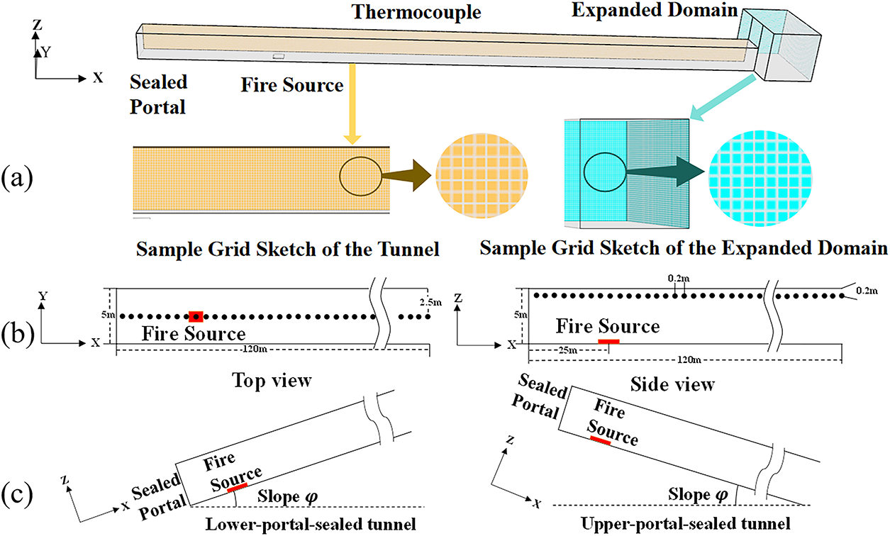
Figure 1: Schematic view of FDS model [17]. (a) Sample grid schematic of tunnel and expanded computational domain; (b) top view and side view of thermocouple arrangement; (c) schematic of tunnels with different slopes and portal sealing conditions
The fire source was modeled using a “BURNER” boundary condition with a prescribed HRR. The combustion of heptane employs a mixed-control chemical reaction, which involves three mixtures to address the combustion process. The reaction was set to “HEPTANE” with a soot yield of 0.015 and CO yield of 0.006, and the combustion area was 2 m (length) × 2 m (width) [17]. The corresponding combustion model is
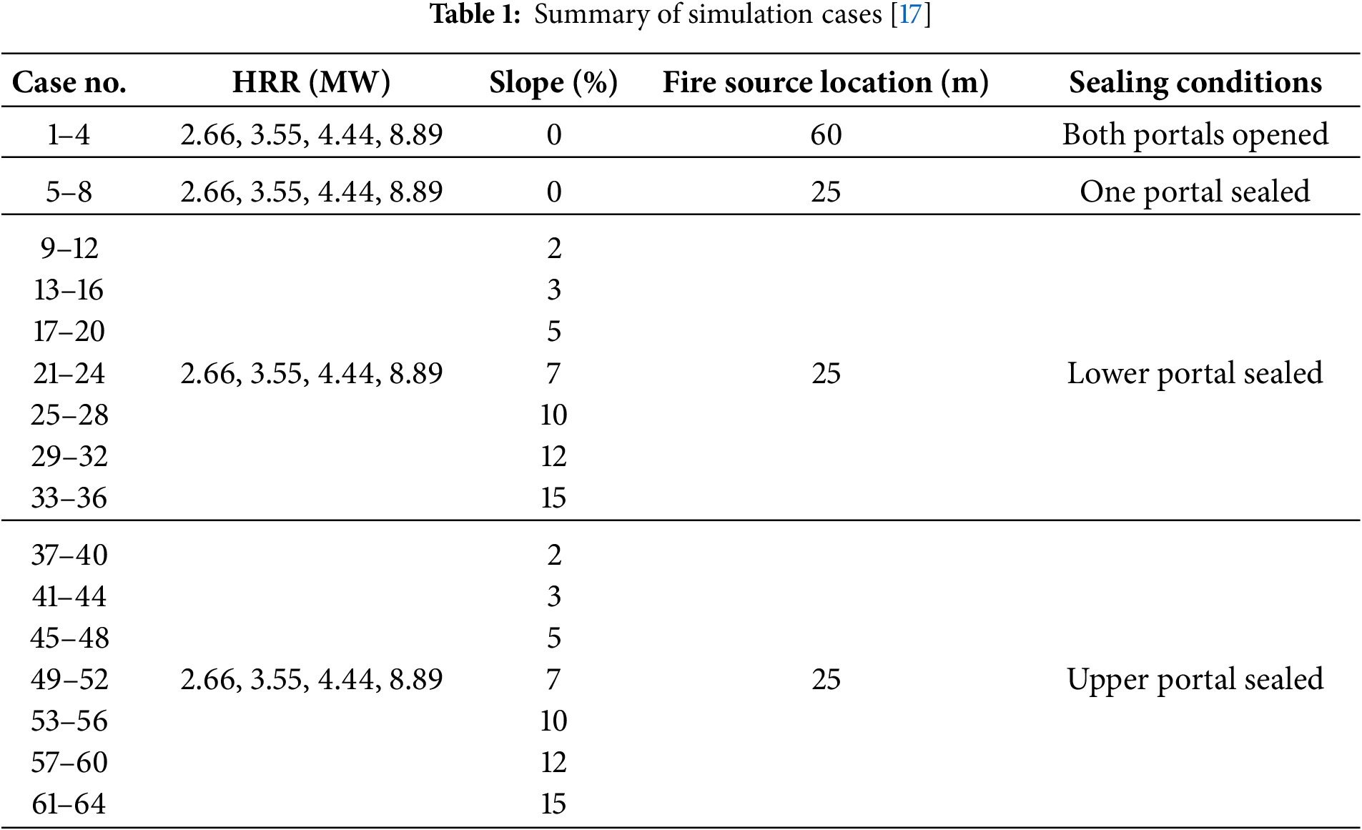
As shown in Fig. 1b, a series of thermocouples with an interval of 0.2 m were placed at 0.2 m below the center line of the tunnel roof to measure the longitudinal temperature below the ceiling. In addition, a thermocouple tree with a longitudinal interval of 5 m was placed, as shown in Fig. 1b (only two strings of thermocouple trees are shown in the figure), and the vertical interval in each string of thermocouple trees was 0.2 m. According to the relevant research [9,20,23], the slopes are 0%, 2%, 3%, 5%, 7%, 10%, 12%, and 15%, respectively. Two sealing conditions were examined, i.e., the lower portal sealed or the upper portal sealed. Additionally, horizontal tunnels with both portals open, as well as horizontally aligned tunnels with one sealed portal at 0% slope, were designated as control groups. In doubly open tunnels with 0% slope [17], to facilitate observation of the fire smoke’s symmetrical flow field, the fire source was positioned at the tunnel’s geometric center. To facilitate the observation of the symmetrical smoke flow field of the fire smoke, the fire source was placed at the geometric center of the tunnel [9,20,23]. In numerical simulations, four kinds of fire source HRRs (i.e., 2.61, 3.47, 4.34, and 8.68 kW), which correspond to full-scale HRRs of 2.66, 3.55, 4.44, and 8.89 MW, respectively, were set up, and the simulation cases are summarized in Table 1. The magnified sample grid sketch of the tunnel and the Expanded Domain is shown in Fig. 1, from which good grid uniformity could be observed.
In the numerical simulation, a grid independence test is an important step to ensure the accuracy and reliability of the calculation results. In this study, with reference to previous research results [7,9,24], when the ratio of the characteristic diameter of the fire source
In order to ensure the value is in the range of 4~16, the grid size range should be 0.09 to 0.59 m. Fig. 2 presents the variation law of flame length with slope under different mesh sizes. It could be seen from the figure that when the grid size increased from 0.1 to 0.2, the change in the simulated data is small, rising by 5%. However, when the grid size is adjusted to 0.3, the increase rises to 15%; and when the grid size is 0.5, it further increases to 37%. In conclusion, the simulated results with mesh sizes of 0.1 and 0.2 m are very close, while further increasing the mesh size will lead to significant errors.
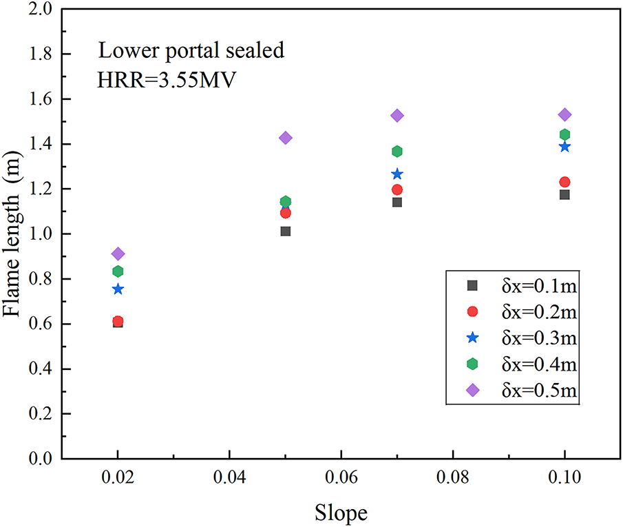
Figure 2: Variation law of flame length with slope under different mesh sizes
Fig. 3 presents a comparison of the temperature measurement values of thermocouple trees M and N under five mesh sizes when the HRR was 4.44 MW [17]. It can be observed from the comparison results that as the mesh size
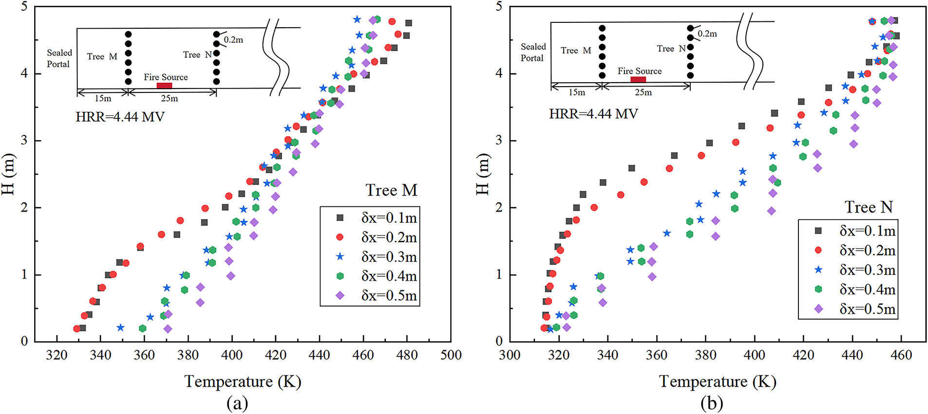
Figure 3: Comparison of temperature distributions under different mesh sizes. (a) comparison of thermocouple tree M; (b) comparison of thermocouple tree N
Fig. 4 shows the thermocouple temperature and HRR curves at different distances from the fire source under the condition with the lower portal sealed. It can be seen that although the sealed boundary restricts the ventilation conditions to a certain extent, the HRR and temperature in the typical operating conditions can reach a stable state within the set simulation time. The last 50 s of each simulation is taken as the quasi-steady state to calculate the average value. The magnified sample grid sketch of the tunnel and the Expanded Domain is shown in Fig. 1a, from which good grid uniformity can be observed.
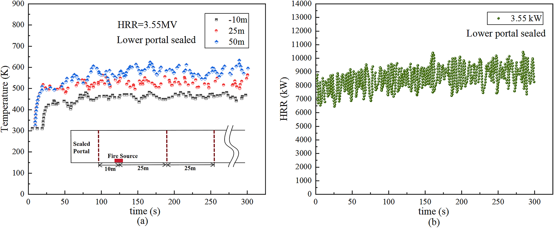
Figure 4: Thermocouple temperature and HRR curves at different distances from the fire source (a) and HRR (b) vs. time
Validating the capability of FDS in tunnel simulations is crucial for numerical studies [14–16]. Its simulation outcomes have shown strong consistency with actual experimental findings, and this reliability has been well confirmed by numerous research efforts. In FDS simulations, the time-averaged flame height can be determined from the integral distribution of the HRR along the vertical direction. Specifically, the height at which the cumulative heat release fraction reaches 95% to 99% is regarded as the flame height, and this study adopts 99% as the threshold. This definition has been validated through comparison with various flame height correlations [21]. Our previous studies have shown that when the excess temperature of 250–300 K are selected as the flame boundary temperatures, the flame lengths obtained are in excellent agreement with those derived from the Heskestad flame model. Among these, the values obtained at the excess temperature of T = 300 K are nearly identical to the results from the 99% fuel consumption method [25]. Furthermore, the reliability of FDS in simulating fire smoke spread has also been thoroughly established in previous studies for two typical tunnel configurations: tunnels with both portals opened and those with one portal sealed [12,26]. To validate the current model, the temperature distribution on the tunnel ceiling was selected for comparison with existing research results. To further verify the simulation accuracy in sealed tunnel scenarios, the numerical simulation results were compared with the 1:10 reduced-scale experimental data from Han et al. [9], which were obtained from an inclined tunnel with a sealed upper portal. Han et al. utilized a tunnel with dimensions of 11 m (length) × 1 m (width) × 0.5 m (height). A pool fire of varying size was used as the fire source, located 2.5 m from the sealed section. Table 2 lists the specific experimental conditions.
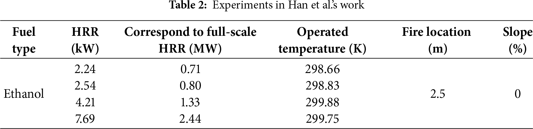
Fig. 5 presents a comparison of smoke temperatures beneath the tunnel ceiling at different longitudinal locations from Han et al.’s experiments and the numerical simulation results. It can be observed that the simulation results show great agreement with the experimental data. In fact, in addition to the above four working conditions, we have also conducted a large number of experimental validations [17,25,27–29]. The results all indicate that, numerical simulation can reasonably well predict the fire smoke movement and fire-induced temperature distribution in tunnel fires. The Mean Absolute Error (MAE) and Root Mean Square Error (RMSE) values are also presented in Fig. 5. It can be seen that the MAE of the simulated smoke temperature is below 15 K, and the RMSE is below 20%. This error level verifies a high degree of consistency between the numerical simulation and experimental results, indicating that the model is reliable. Therefore, employing FDS for subsequent research endeavors is both methodologically sound and technically reliable.
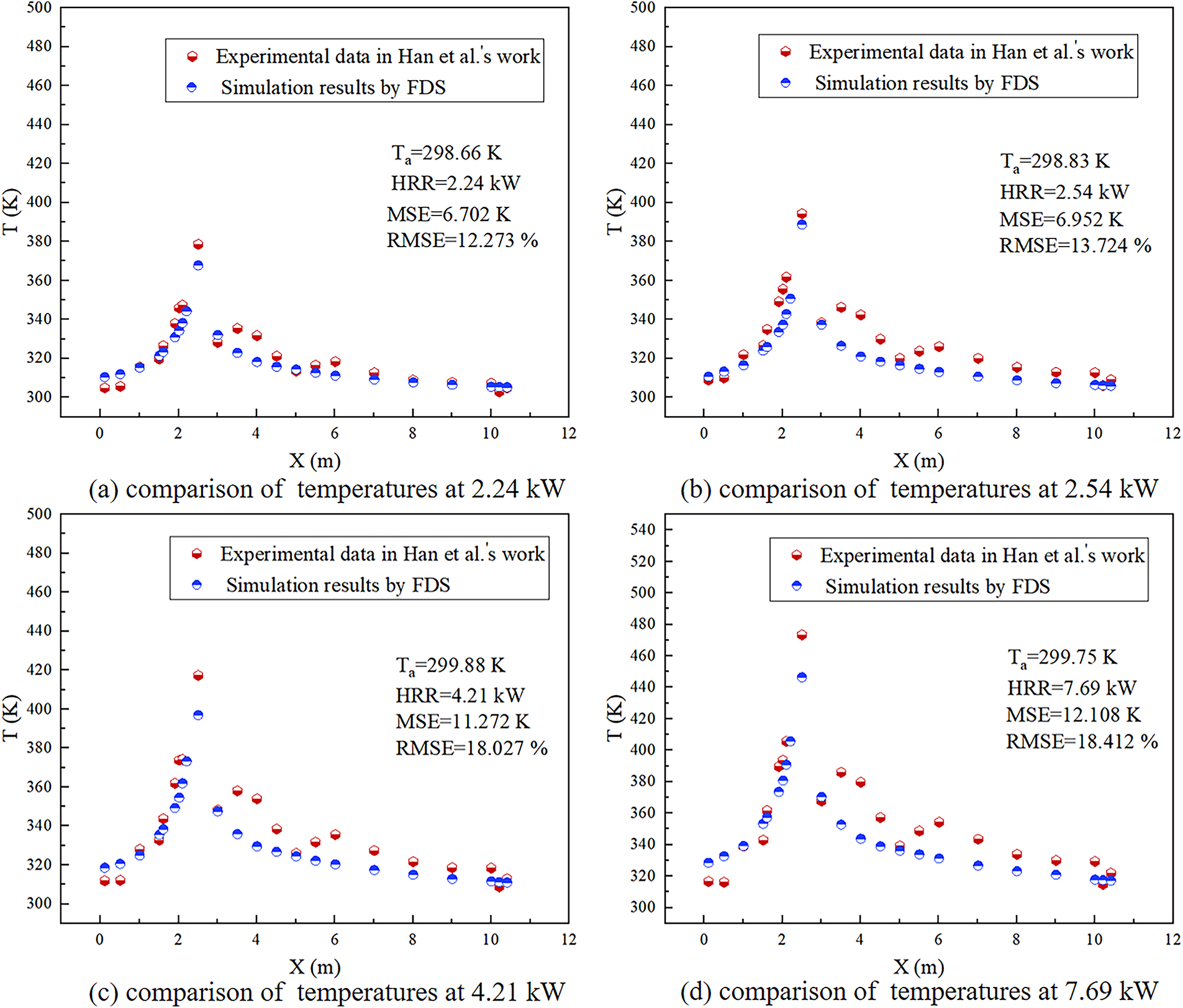
Figure 5: Validation of numerical method by experimental results
The deflection characteristics of flames and the quantitative analysis of flame length have important guiding significance for predicting fire scale, assessing fire risk, and guiding building fire protection design. Taking the simulation case with HRR = 2.66 MW as an example, Fig. 6 illustrates the flame shapes under different tunnel sealing conditions. In Fig. 6a,b, it can be found that during the initial combustion stage (10~20 s), the flame is perpendicular to the bottom of the tunnel, impinges on the ceiling, and is approximately axisymmetric. The temperature fields on both sides of the fire source are also evenly distributed. After reaching the quasi-steady-state phase (270~280 s), at this point, all parameters are basically stable, due to the presence of the sealed portal in Fig. 6b, the flame will undergo asymmetric entrainment after a period of time, and deflect toward the sealed portal. This is because the open portal predominantly supplies the air required for normal combustion, and restricted air entrainment on the sealed portal side results in entrainment asymmetry.
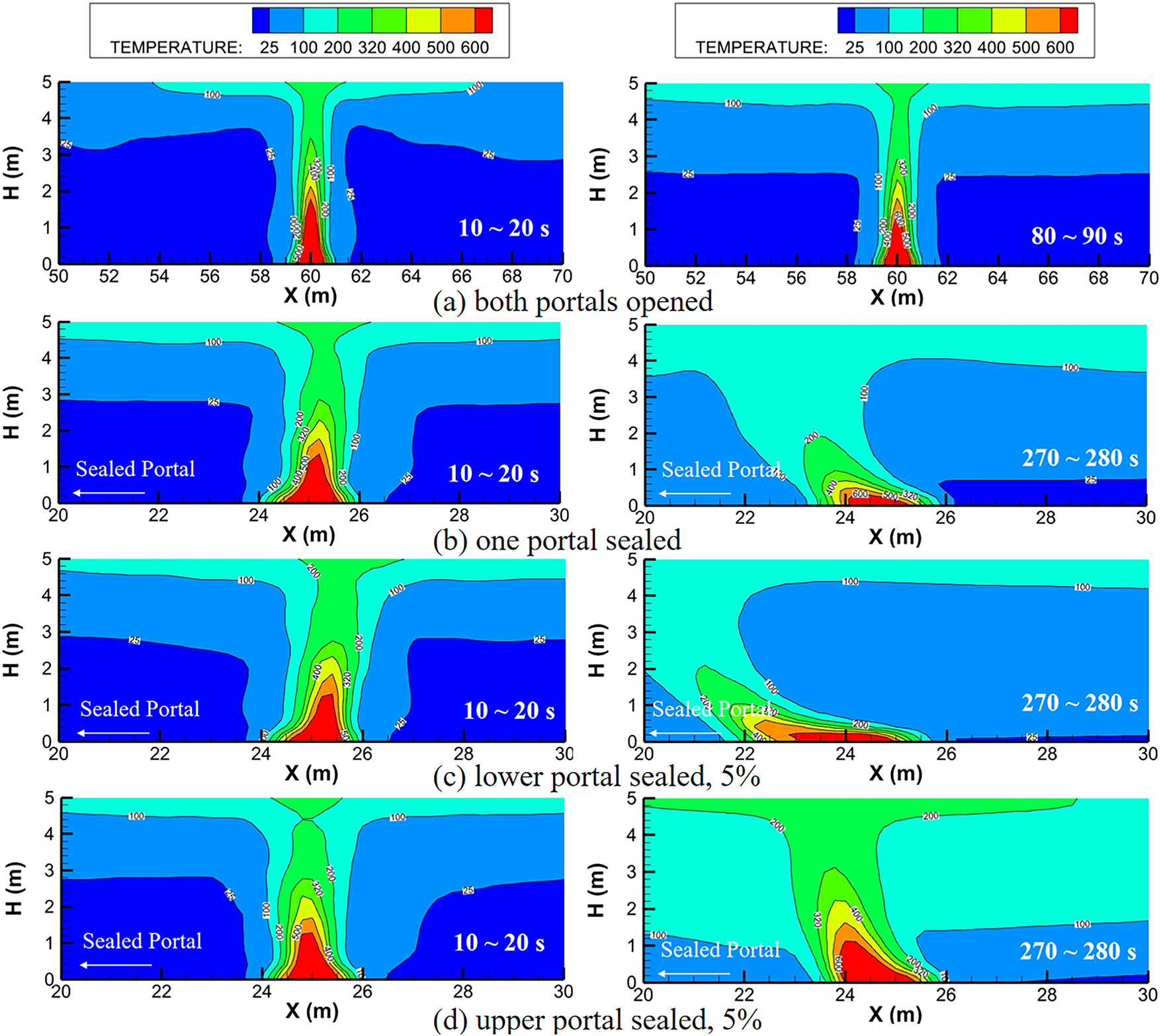
Figure 6: Flame shape under different sealing conditions
As illustrated in Fig. 6a, the flame in the tunnel with two open portals exhibits no deflection, with the temperature distribution remaining uniform on both sides. Additionally, in the tunnel with one portal sealed, the temperature field near the fire source is higher, and the smoke layer is thicker compared to the fully open tunnel. This difference mainly stems from the higher wind speed at the open portal, leading to the accumulation of high-temperature smoke. As illustrated in Fig. 6b–d, the flame assumes a relatively vertical shape and consistent surrounding temperature field distributions during the initial combustion stage, whether the upper or lower portal is sealed. At the steady state, however, flame deflection occurs universally. The main findings can be summarized as follows: (1) Inclined tunnels with lower portals sealed demonstrate the most significant flame deflection, exceeding that observed in horizontal tunnels with one portal sealed; (2) The steady state average temperatures in inclined tunnels consistently surpass those in horizontal tunnels, regardless of sealing position. This issue concerns the safety of personnel in the “sealed portal-fire source” area and requires special attention.
The flame tilt angle is defined for different flame development patterns. It is noteworthy that, with reference to previous research [25], a 300 K temperature rise is used as the flame boundary in this study. On this flame boundary line, the farthest distance from the ignition source point is considered the flame tip. Fig. 7 graphically defines the flame tilt angle
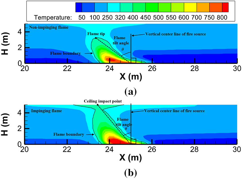
Figure 7: Definition of flame tilt angle in different flame development patterns. (a) schematic of flame tilt angle definition for non-impinging; (b) schematic of flame tilt angle definition for impinging ceiling flame
Fig. 8 shows the variation of flame tilt angle with slope under different sealing conditions. In the tunnels with a lower portal sealed, the flame tilt angle changes irregularly with the increasing slope. This may be because the flame base (lower part) deflects toward the sealed portal under the influence of confined longitudinal cold airflow, while the top of the flame (upper part) is inclined to the open portal due to the stack effect. Under different conditions, these two influencing factors do not have absolute advantages under the action of the slope, resulting in irregular changes in flame shape. In addition, the flame tilt angle in the inclined tunnel is larger than that in the horizontal tunnel, and the flame tilt angle at the same slope decreases with the increase of the HRR.
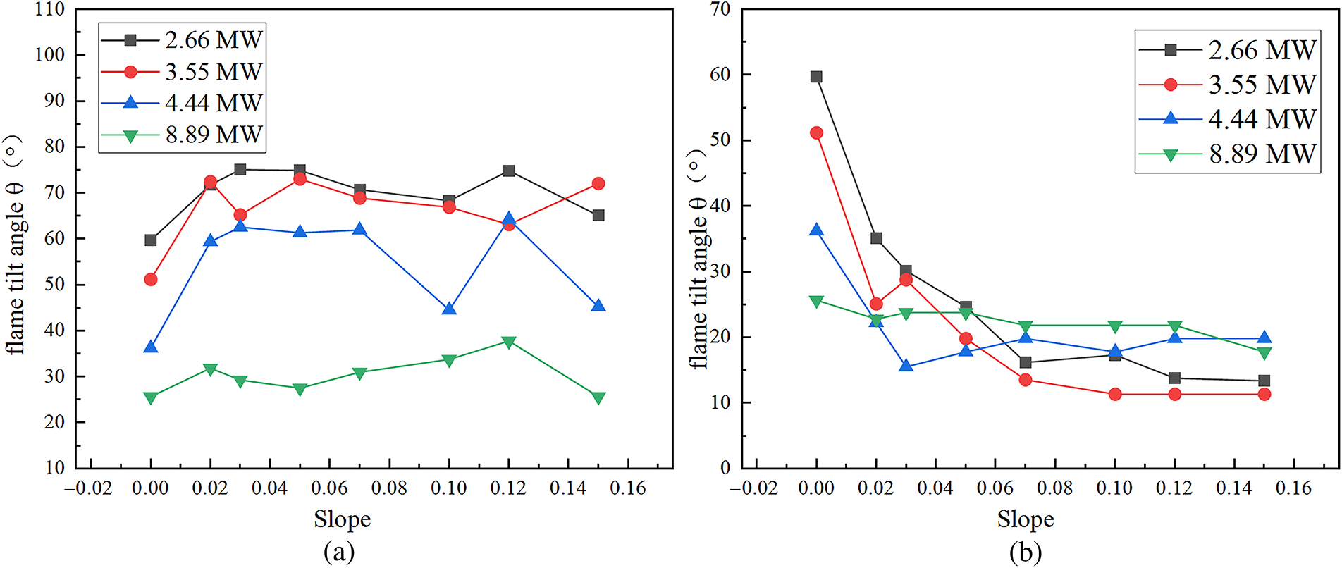
Figure 8: Variation of flame tilt angle with slope under different sealing conditions. (a) Lower portal sealed; (b) Upper portal sealed
In the tunnel with the upper portal sealed, the flame tilt angle decreases with the increase of slope. The flame tilt angle is jointly governed by the longitudinal cold airflow and the stack effect. When the slope increases, the stack effect increases. Under these sealing conditions, the influence of the stack effect predominates over that of the longitudinal airflow, and the stack effect becomes the dominant factor. In addition, the decrease of the inclination angle slows down with the increase of the HRR, and the flame tilt angle in the horizontal tunnel is larger than that in the inclined tunnel.
Fig. 9 shows the definition of flame length
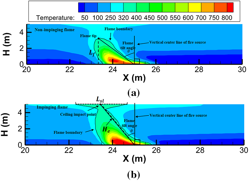
Figure 9: Definition of flame length for different flame patterns. (a) schematic of flame length definition for non-impinging flame; (b) schematic of flame length definition for impinging flame
Fig. 10 shows the calculation results of the flame length under different sealing conditions. The black demarcation line indicates the tunnel height (H = 5 m), conditions above this line represent scenarios with the ceiling impinging flames, while those below it correspond to the non-impinging flames. It can be found that the flame is comprehensively affected by the slope and sealing conditions, and there are both cases of impinging on the ceiling and non-impinging on the ceiling in the tunnels under the two sealing conditions. For example, at an HRR of 8.89 MW, flames impinge on the ceiling in both sealing conditions. However, at HRR values of 3.55 and 4.44 MW in the upper portal sealed tunnel, both impinging and non-impinging flames coexist. Therefore, HRR significantly influences flame length, with its impact exceeding that of slope. In lower portal sealed tunnels, variations in HRR and slope have minimal impact on the flame length of non-impinging flames, while the impinging flame length increases with the increase of the slope. A critical aspect of impinging flame behavior is whether flame quenching occurs upon contact with the tunnel ceiling. In this study, the concrete ceiling is modeled as an inert solid boundary without prescribed surface reactions [30]. Heat extraction at the interface occurs primarily through convective cooling, governed by the resolved flow dynamics, and conductive heat loss into the solid material [31]. Given the high flame temperatures observed in the simulations and the considerable thermal inertia of the concrete, complete flame quenching, specifically radical termination leading to flame extinction, at the ceiling surface is considered unlikely despite the presence of a steep temperature gradient. In tunnels with the upper portal sealed, for impinging flames, flame length increases with the increasing slope and HRR. Conversely, non-impinging flames exhibit significantly lower sensitivity to variations in both HRR and slope.
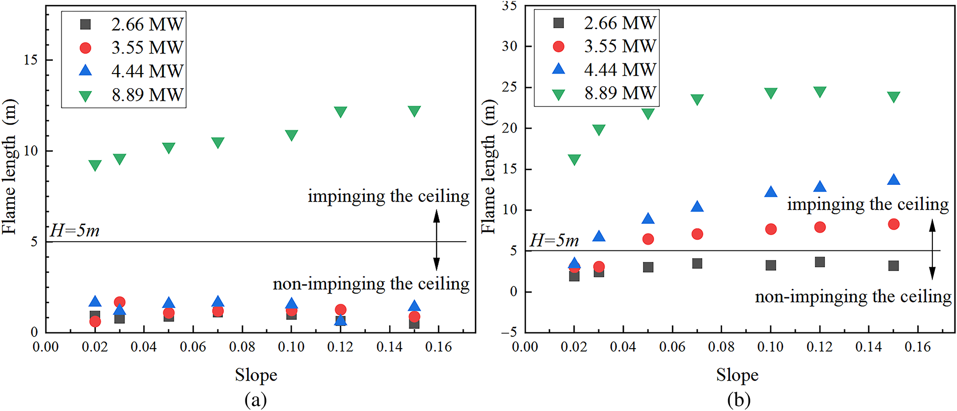
Figure 10: Flame length in tunnels under different sealing conditions. (a) lower portal sealed; (b) upper portal sealed
McCaffrey et al. [32,33] proposed a classical flame length model:
where D is the equivalent diameter of the fire source, m. In this study, the area of the rectangular fire source is 4
Therefore, under different sealing conditions, the flame length
Referring to Eq. (6), the flame length
Fig. 11 quantifies the relationship between the fitting coefficient
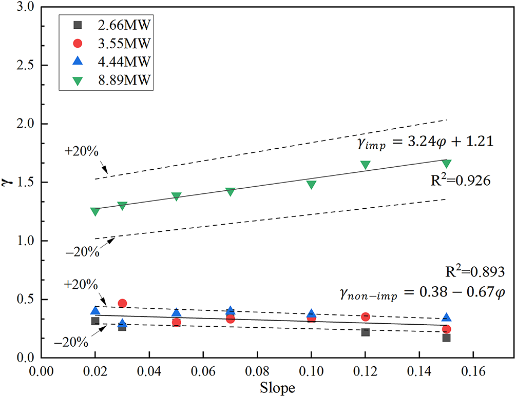
Figure 11: Relationship between fitting coefficient and slope
Substituting Eqs. (9) and (10) into Eq. (8) yields a flame length prediction model for both impinging flames and non-impinging flames in lower portal sealed tunnels.
Flame length for non-impinging flames:
Flame length for impinging flames:
Referring to Eq. (6), the flame length
The applicable slope range of this model is from 0° to 15°. In tunnels with the upper portal sealed, Fig. 12 shows the relationship between coefficient
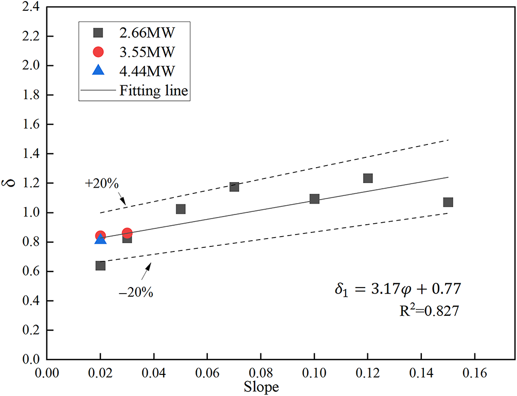
Figure 12: Relationship between fitting coefficient
Fig. 13 shows the relationship between fitting coefficient
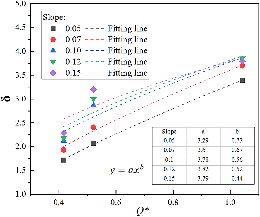
Figure 13: Relationship between fitting coefficient
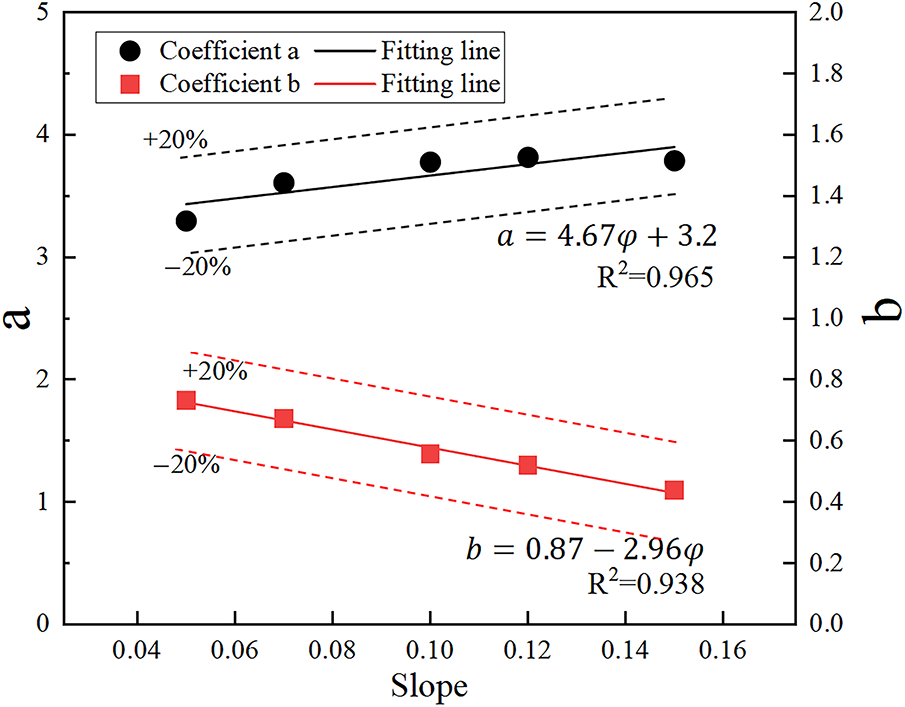
Figure 14: Relationship between coefficient
Substituting Eqs. (15) and (16) into Eq. (14) yields a flame length prediction model for both impinging and non-impinging flames in upper portal sealed tunnels.
Flame length for non-impinging flames:
Flame length for impinging flames:
The applicable slope range of this model is from 0° to 15°. In order to verify the reliability of the model, the numerical simulation data are compared with the model prediction values. As shown in Fig. 15, the predicted values of the model are in good agreement with the simulated measured values, and most of the errors are within 20%. Therefore, Eqs. (12), (13), (17) and (18) can satisfactorily predict flame lengths for both non-impinging and impinging flames in inclined tunnels with upper and lower portal sealed. Among them, Eq. (12) demonstrates the smallest prediction error and achieves the closest match to measured data.
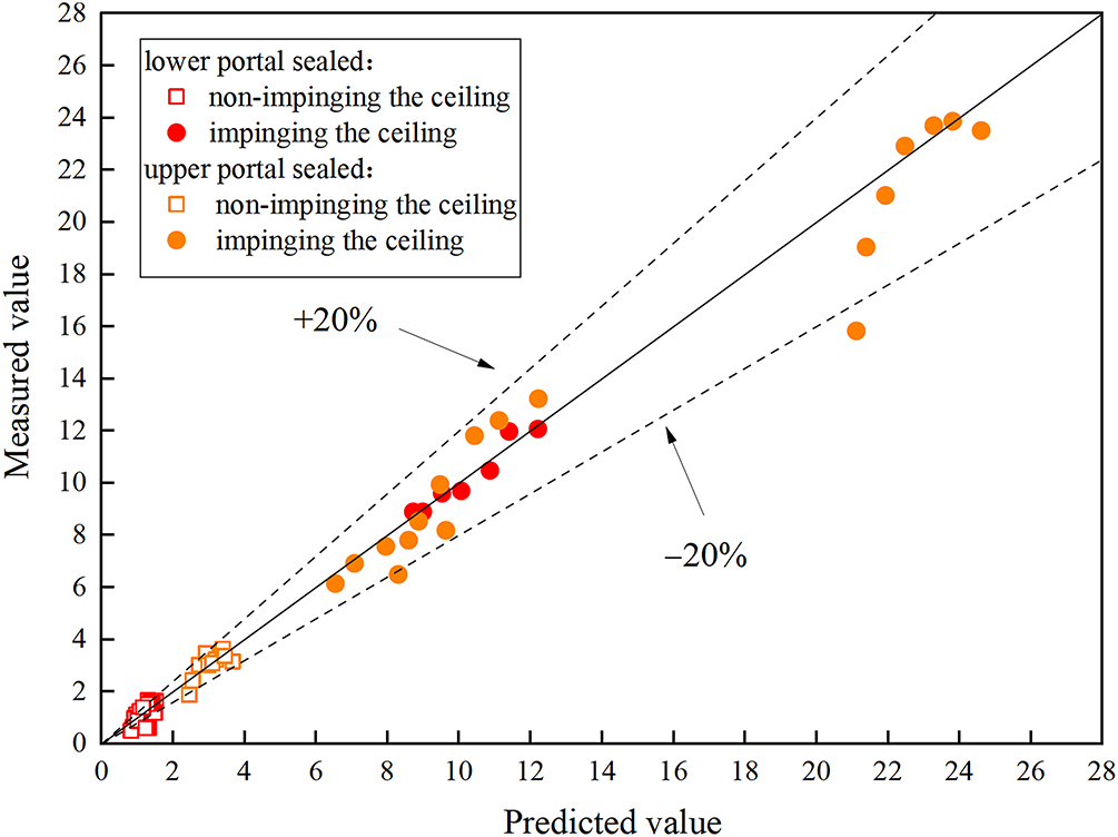
Figure 15: Comparison between predicted values of flame length models and measured values in numerical simulations
3.3 SMFR and Induced Velocity at Tunnel Portal
The SMFR is an important parameter of the longitudinal spread characteristics of smoke in the tunnel, which can be used to guide the design of tunnel ventilation and smoke exhaust. Studying its variation along the longitudinal direction of the tunnel can provide a certain theoretical basis and reference for the design of ventilation and smoke exhaust systems in inclined tunnels with one portal sealed, such as the design of smoke exhaust outlets in transverse smoke exhaust systems [34–36]. This study obtained the induced flow velocity by setting up velocity monitoring slices at the tunnel portal in FDS. Our previous research indicates that, when the upper portal is sealed, the interface between the smoke layer and the air layer is approximately horizontal, rendering it relatively difficult for smoke to spill out of the tunnel [17]. Furthermore, during the process of smoke filling the tunnel, it will engulf the flame, resulting in no clear flow direction and stratification (referring to stratification parallel to the floor) in the tunnel. Therefore, this paper only analyzes the smoke flow at the tunnel portal with the lower portal sealed.
Fig. 16 shows the longitudinal distribution of SMFR under different cases. The SMFR in inclined tunnels is larger than that in horizontal tunnels under the same HRR, and it increases as the slope increases. This is attributed to the enhanced entrainment caused by the increasing slope, leading to a gradual increase in the smoke overflow flow rate. In addition, for a small HRR, the SMFR exhibits a decreasing trend with the increase in longitudinal distance. At a larger HRR (such as 8.89 MW), the mass flow rate initially increases slightly and then decreases, but the overall trend remains decreasing. This represents a notably distinct phenomenon diverging from conventional scenarios. The underlying mechanism is that a higher HRR of the fire source corresponds to a greater SMFR. A higher HRR induces the ceiling jet to necessitate a greater distance for its development, thereby delaying the transition to one-dimensional propagation.
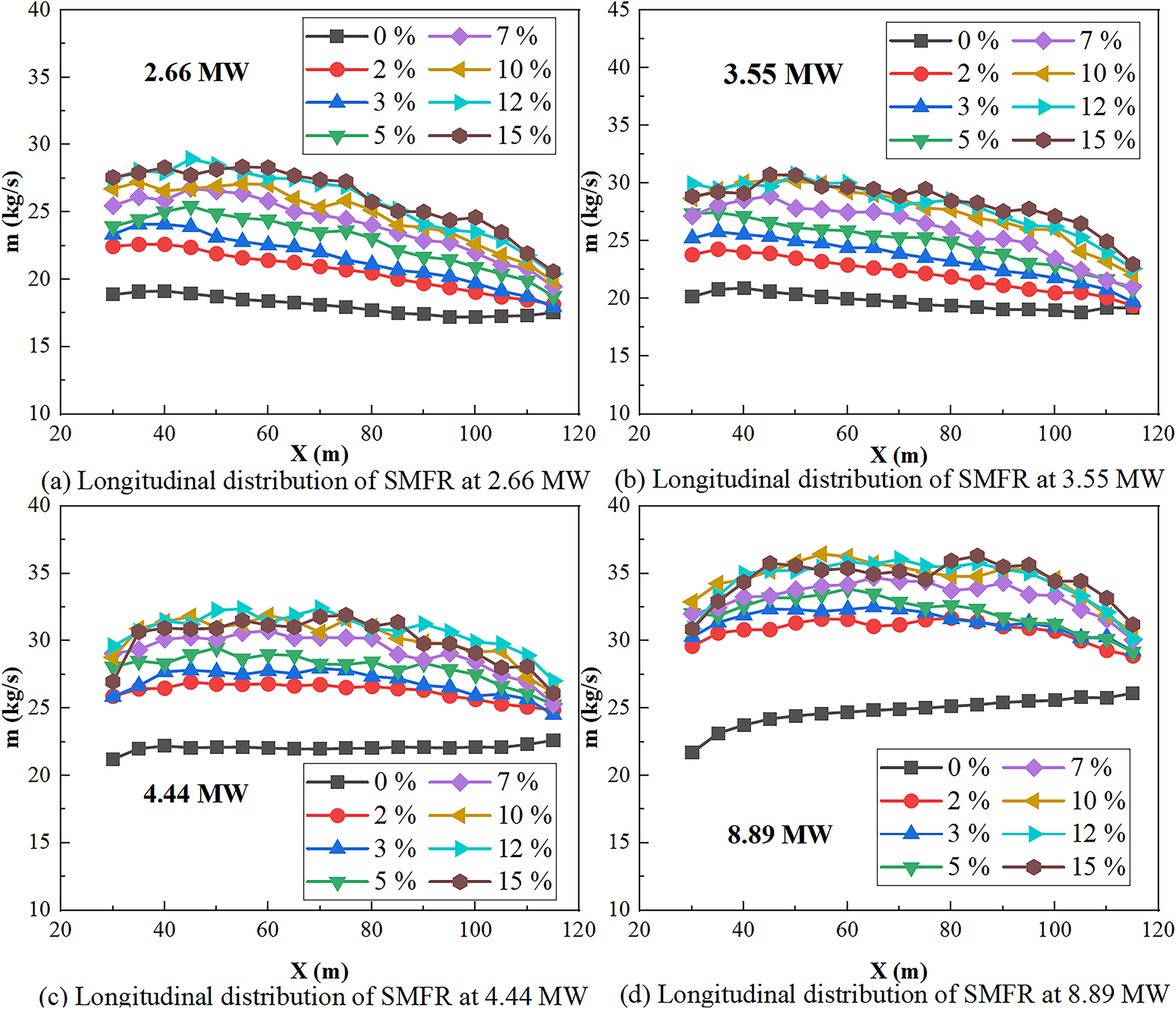
Figure 16: Longitudinal distribution of SMFR
The reduction in mass flow rate is a particularly interesting phenomenon, and the primary reasons for this phenomenon are as follows. When a fire ignites in an inclined tunnel with its lower portal sealed, smoke propagates toward the open portal under thermal buoyancy and the stack effect. In the process of smoke flow, convective shear between cold air incoming from the open portal and the smoke layer induces entrainment of effluent carried by the smoke by the cold airflow. This entrained mixture then reverses direction, flowing back toward the fire source. Concurrently, ambient air is continuously entrained into the smoke layer. Fig. 17 illustrates the entrainment mechanism diagram during smoke diffusion. In this figure, the smoke and air in a unit length of the tunnel are taken as a control body. The smoke mass entering the control body is
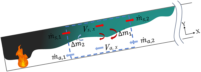
Figure 17: Schematic diagram of entrainment during smoke diffusion
During convective shear between the air and smoke layers, the entrainment of air by smoke (
Fig. 18 shows the neutral plane height at a certain location from the fire source. Specifically, at the smoke front (L meters from the fire source), the static pressure line of the cold air on the right side appears as a diagonal line with a negative angle, indicating that the pressure increases as the height decreases. Inside the hot smoke, due to the higher temperature and lower density of the smoke, the slope of its static pressure line differs from that of the cold air. According to the principle of pressure curve continuity, these two lines must intersect at a specific height; the cross-section corresponding to this height is the neutral plane, and this corresponding height is referred to as the neutral plane height
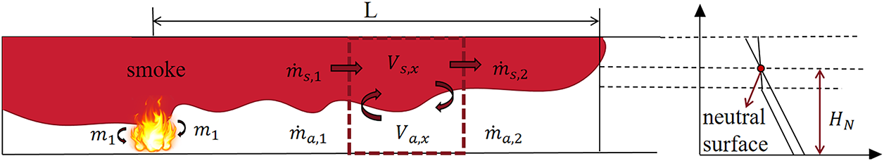
Figure 18: Pressure diagram at a certain location from the fire source
At any position x m, the movement velocity of the smoke layer can be expressed as a function of height z. By combining with the ideal gas state equation, we can obtain the following:
At the position of x = L, the SMFR between the heights of
In the equation,
It can be seen from Eqs. (22)–(24) that the change in mass flow rate is related to parameters such as temperature and neutral plane height. According to what has been stated previously, during the spread of smoke, it must be accompanied by heat loss and changes in the entrainment mechanism. Thus, it is reasonable to infer that the pressure profiles at different locations, including the position of the neutral layer, will change, thereby leading to changes in the mass flow rate.
Fig. 19 shows the variation of the SMFR at the tunnel portal with the slope. It can be found that the SMFR gradually increases with the increase of the tunnel slope. This is because an increase in the slope strengthens the stack effect, increasing the velocity of smoke as it exits the open portal of the tunnel and thereby increasing the mass of smoke passing through the open portal’s cross-section per unit time. Additionally, under the same slope, SMFR gradually increases with the HRR due to the generation of more smoke.
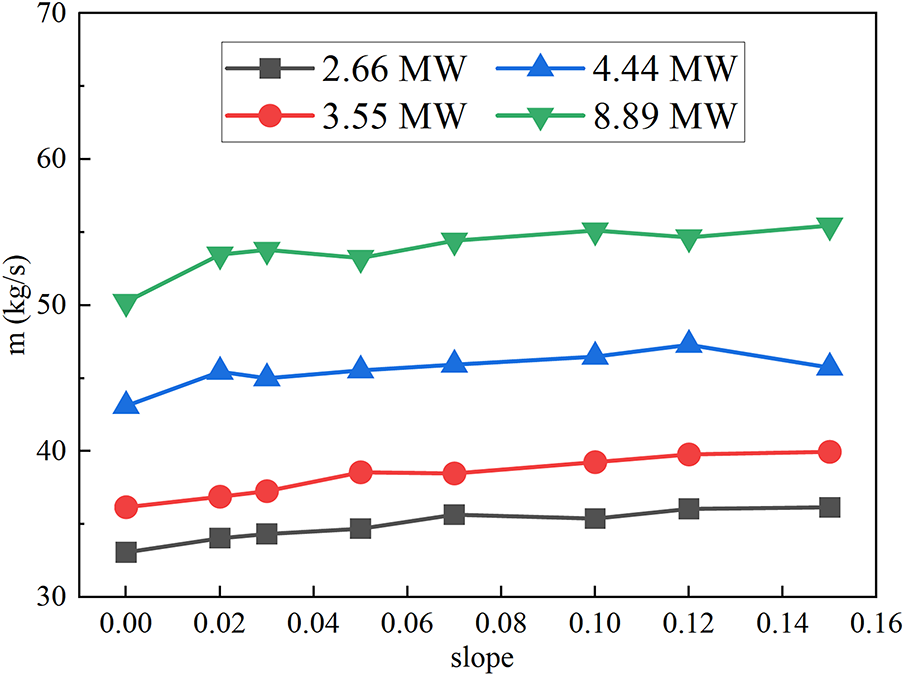
Figure 19: Variation pattern of SMFR vs. slope at the tunnel open portal
After a fire occurs in a horizontal tunnel sealed at one portal, the smoke has an initial propagation velocity due to the thermal buoyancy of the smoke, and the air entrained by the flame also has an initial flow velocity. However, when the tunnel is inclined, the stack effect affects the flow velocity of smoke and air. Gao et al. [20] pointed out that the induced velocity at the portal is investigated by analyzing the pressure and temperature distributions across the cross-section of the tunnel entrance. The pressure difference determines how the hot smoke and cold air pass through the tunnel portal. The surface with a pressure difference of 0 Pa can be defined as a neutral plane [20]. Above the neutral plane (>0 Pa), the hot smoke will be discharged outside the tunnel, and under the neutral plane (<0 Pa), the air will be entrained into the tunnel. In addition, considering the influence of HRR, tunnel size, and slope, a dimensionless induced air velocity prediction model suitable for inclined tunnels can be proposed:
where
Taking the scenarios with HRR = 2.66 MW as examples, Fig. 20 presents the contours of pressure and temperature distribution at the tunnel portal under different slopes, where the neutral plane, characterized by a pressure difference of 0 Pa cross-section of the tunnel’s open portal, is defined as the dividing line. As the slope increases, the height of the dividing line increases continuously. The average pressure above the dividing line decreases slightly with the increase of slope, and the average pressure under the dividing line increases with the increase of slope. In addition, the temperature stratification at the outlet is better, and the temperature of the smoke layer gradually decreases. Compared with other working conditions, the average temperature of the smoke layer at the portal of the horizontal tunnel is larger, and the smoke layer is thinner.
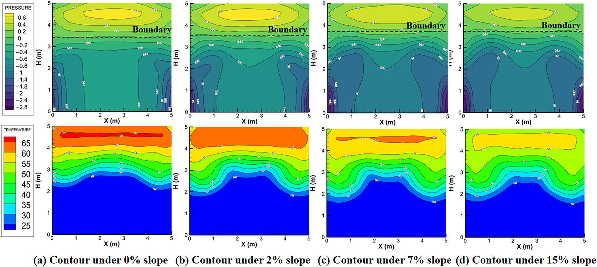
Figure 20: Contours of pressure and temperature distribution at the tunnel portal under different slopes
In this study, the induced smoke flow velocity
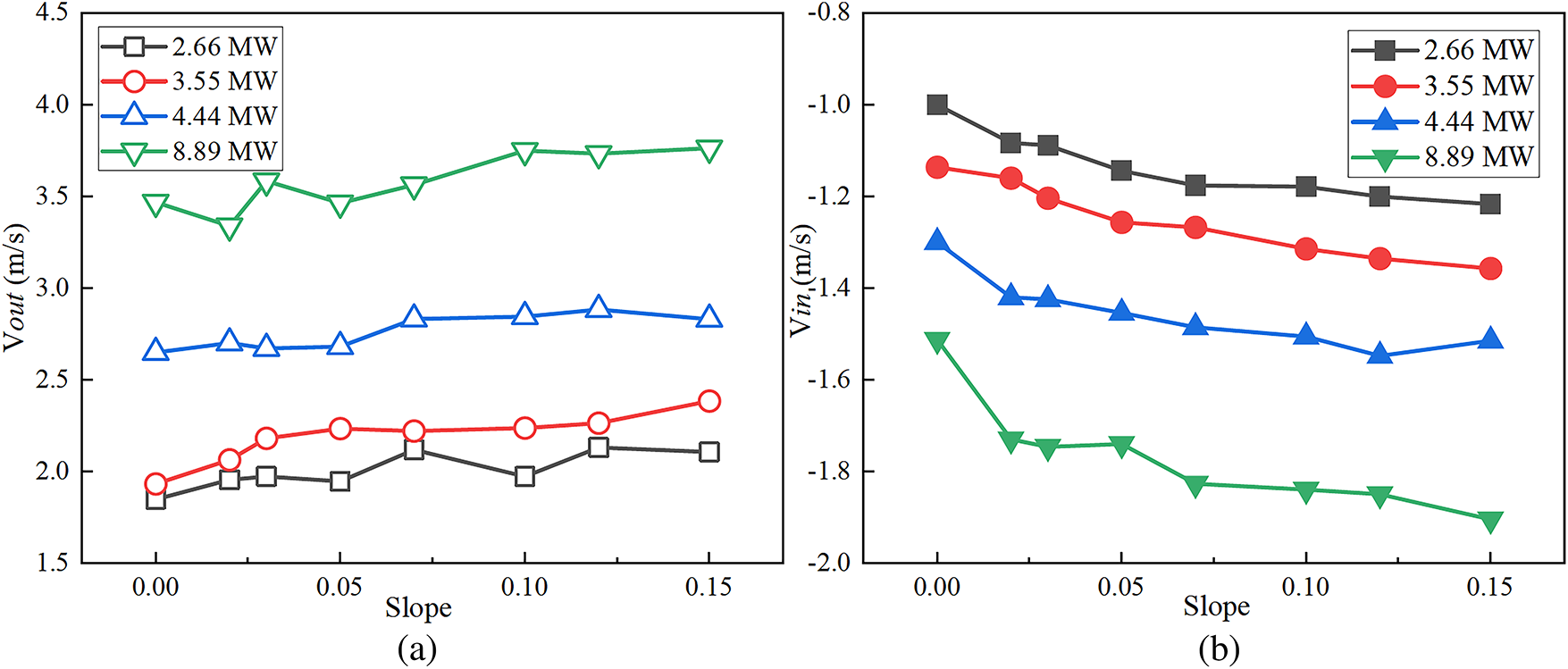
Figure 21: Variation of induced wind velocity at tunnel portal (X = 120 m). (a) at under different slopes and HRR; (b) at under different slopes and HRR
Based on the Eqs. (25)–(28), combined with the boundary conditions of numerical simulation, the dimensionless treatment of the calculated induced wind velocity and tunnel-related parameters is carried out. It should be noted that the velocity is inherently correlated with density in fluid dynamics principles. However, in the context of this tunnel fire simulation, the density variation can be taken as negligible (beyond a certain distance from the fire source, the rate of smoke temperature attenuation is negligible [38]). Fig. 22 shows the variation of dimensionless velocity
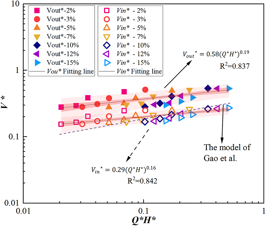
Figure 22:
Dimensionless induced smoke flow velocity:
Dimensionless thermally-induced air inflow velocity:
In Fig. 22, Eqs. (29) and (30) are also compared with the model of Gao et al. [20]. It can be found that Gao’s model is slightly smaller than the smoke velocity prediction model. This may be because Gao et al.’s research object is an inclined tunnel with both portals open, and the induced air velocity prediction model they proposed targets the lower portal. The inclination of the tunnel causes the stack effect; however, compared with tunnels with both portals open, the stack effect in the tunnel is enhanced due to the sealed lower portal, resulting in a higher smoke velocity. Regarding the air inflow velocity, in Gao’s study, the induced air velocity at the lower portal hinders smoke overflow, with only a small amount of smoke flowing out from the lower portal. Even in tunnels with larger slopes, a countercurrent length is formed with no smoke overflow, and the growth rate of air velocity below the neutral plane is slightly higher.
Fig. 23 shows the comparison between the predicted values of Eqs. (29) and (30) and the measured values from numerical simulations. The results show that the error of most predicted values can be controlled within 20%. Therefore, it is considered that the Eqs. (29) and (30) can well predict the smoke-induced velocity and air-induced velocity at the outlet of the lower portal sealed inclined tunnel.
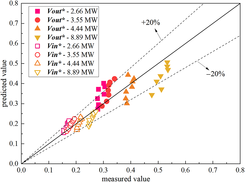
Figure 23: Comparison between predicted and measured values of dimensionless induced wind velocity
This study reveals the flame deflection, temperature distribution, and the effects of portal sealing conditions and tunnel slope on them in inclined tunnel fires by numerical simulations, which is of crucial guiding significance for predicting fire scale, assessing fire risk, optimizing tunnel ventilation design, guiding building fire protection design, and other aspects. However, this study still has several limitations that need to be addressed in future work to further refine and extend its findings. Firstly, it does not systematically examine the influence of tunnel cross-sectional shapes (e.g., circular, rectangular, or arched) on fire behavior under different sealing conditions. Moreover, it does not sufficiently consider the effect of broader variations in tunnel size on smoke dispersion and flame characteristics. Secondly, the models proposed in this study are not applicable to scenarios with extremely high HRR or tunnels with extremely steep slopes. Future research should prioritize integrated multi-parameter analyses of fire dynamics that incorporate these factors to enhance the applicability and engineering relevance of the conclusions.
Numerical simulations were used to investigate flame deflection, flame length, smoke mass flow rate, and induced velocities at tunnel portals in inclined tunnel fires, considering influencing factors such as slope and sealing conditions etc. The main conclusions are summarized as follows:
(1) In the initial combustion stage in all fire scenarios, the flames are vertically upward. When one portal is sealed, the flame tilts toward the sealed portal during the quasi-steady stage. When a slope exists, the deflection degree of the flame in the tunnel with the lower portal sealed is the largest, and the average temperature in the inclined tunnel is higher than that in the horizontal tunnel.
(2) The slope significantly affects the flame tilt angle. When the lower portal is sealed, the flame tilt angle varies irregularly as the slope increases. Conversely, when the upper portal is sealed, the flame tilt angle decreases with the increasing slope. The HRR exerts a more significant influence on flame length than the tunnel slope. Ultimately, prediction models of flame length for both impinging and non-impinging flames are developed based on the different sealing conditions.
(3) When the lower portal is sealed, the smoke mass flow rate increases with the increasing slope, and is greater than that in horizontal tunnels. At the tunnel portal, both the induced smoke flow velocity and the fire-induced air inflow velocity increase with the increasing tunnel slope and HRR. Based on the model of Gao et al., two dimensionless induced wind velocity prediction models, namely the dimensionless induced smoke flow velocity prediction model and the dimensionless thermally-induced air inflow velocity prediction model, are constructed.
The main conclusion on the variation patterns of flame deflection angle and flame length can serve as an important reference for predicting fire scale and assessing the probability of fire spread. In addition, the quantitative analysis of the smoke mass flow rate contributes to the ventilation and smoke exhaust design under specific sealing conditions. Furthermore, regulation of the induced velocity directly influences the extent of smoke spread and represents a key parameter in the design of longitudinal ventilation systems, thus directly affecting the smoke control effect of tunnel fires. These results provide practical guidance for enhancing tunnel fire safety design.
Acknowledgement: Thanks to the Ventilation Laboratory of the School of Thermal Energy Engineering for providing materials and equipment, and to Yang Haoran for offering valuable discussions and technical support during his time at Shandong Jianzhu University.
Funding Statement: This work was financially supported by National Natural Science Foundation of China (NSFC) under Grant No. 52208115, Science and Technology Support Plan for Youth Innovation of Colleges and Universities of Shandong Province of Chain (No. 2023KJ122), Leading Researcher Studio Fund of Jinan (No. 202333050), Natural Science Foundation of Shandong Province (ZR2024ME027), Young Talent of Lifting engineering for Science and Technology in Shandong, China (SDAST2024QTA077).
Author Contributions: The authors confirm contribution to the paper as follows: study conception and design: Shengzhong Zhao, Daiyan Chen, Han Zhang; data collection: Han Zhang, Daiyan Chen; analysis and interpretation of results: Shengzhong Zhao, Lin Xu, Junhao Yu; draft manuscript preparation: Daiyan Chen, Fei Wang and Zhaoyi Zhuang. All authors reviewed the results and approved the final version of the manuscript.
Availability of Data and Materials: The authors confirm that the data supporting the findings of this study are available within the article and its supplementary materials. The data that support the findings of this study are available from the corresponding author, [ZH/WF], upon reasonable request.
Ethics Approval: Not applicable.
Conflicts of Interest: The authors declare no conflicts of interest to report regarding the present study.
References
1. Yu L, Lei X, Huang P, Liu C, Zhang H, Yang F. Study on the combination effect of tunnel slope and longitudinal fire location on the asymmetric flow fields in a naturally ventilated tunnel. Tunn Undergr Space Technol. 2024;146:105623. doi:10.1016/j.tust.2024.105623. [Google Scholar] [CrossRef]
2. Yi L, Lan S, Wang X, Bu R, Zhou Y. Study on the smoke back-layering length in a tilted tunnel with vertical shaft under natural ventilation. Case Stud Therm Eng. 2022;39:102412. doi:10.1016/j.csite.2022.102412. [Google Scholar] [CrossRef]
3. Guo Q, Zhu H, Zhang Y, Yan Z. Theoretical and experimental studies on the fire-induced smoke flow in naturally ventilated tunnels with large cross-sectional vertical shafts. Tunn Undergr Space Technol. 2020;99(4):103359. doi:10.1016/j.tust.2020.103359. [Google Scholar] [CrossRef]
4. Yao Y, Li YZ, Ingason H, Cheng X. The characteristics of under-ventilated pool fires in both model and medium-scale tunnels. Tunn Undergr Space Technol. 2019;87:27–40. doi:10.1016/j.tust.2019.02.004. [Google Scholar] [CrossRef]
5. Oka Y, Atkinson GT. Control of smoke flow in tunnel fires. Fire Saf J. 1995;25(4):305–22. doi:10.1016/0379-7112(96)00007-0. [Google Scholar] [CrossRef]
6. Wu Y, Bakar MZA. Control of smoke flow in tunnel fires using longitudinal ventilation systems—a study of the critical velocity. Fire Saf J. 2000;35(4):363–90. doi:10.1016/s0379-7112(00)00031-x. [Google Scholar] [CrossRef]
7. Yao Y, He K, Peng M, Shi L, Cheng X, Zhang H. Maximum gas temperature rise beneath the ceiling in a portals-sealed tunnel fire. Tunn Undergr Space Technol. 2018;80:10–5. doi:10.1016/j.tust.2018.05.021. [Google Scholar] [CrossRef]
8. Wang Z, Han J, Wang J, Geng P, Weng M, Liu F. Temperature distribution in a blocked tunnel with one closed portal under natural ventilation. Tunn Undergr Space Technol. 2021;109:103752. doi:10.1016/j.tust.2020.103752. [Google Scholar] [CrossRef]
9. Han J, Liu F, Wang F, Weng M, Wang J. Study on the smoke movement and downstream temperature distribution in a sloping tunnel with one closed portal. Int J Therm Sci. 2020;149:106165. doi:10.1016/j.ijthermalsci.2019.106165. [Google Scholar] [CrossRef]
10. Chen C-K, Xiao H, Wang N-N, Shi C-L, Zhu C-X, Liu X-Y. Experimental investigation of pool fire behavior to different tunnel-end ventilation opening areas by sealing. Tunn Undergr Space Technol. 2017;63(1):106–17. doi:10.1016/j.tust.2017.01.001. [Google Scholar] [CrossRef]
11. Chen C-K, Zhu C-X, Liu X-Y, Yu N-H. Experimental investigation on the effect of asymmetrical sealing on tunnel fire behavior. Int J Heat Mass Transf. 2016;92:55–65. doi:10.1016/j.ijheatmasstransfer.2015.08.079. [Google Scholar] [CrossRef]
12. Huang Y, Li Y, Dong B, Li J, Liang Q. Numerical investigation on the maximum ceiling temperature and longitudinal decay in a sealing tunnel fire. Tunn Undergr Space Technol. 2018;72:120–30. doi:10.1016/j.tust.2017.11.021. [Google Scholar] [CrossRef]
13. Yao Y, Li YZ, Lönnermark A, Ingason H, Cheng X. Study of tunnel fires during construction using a model scale tunnel. Tunn Undergr Space Technol. 2019;89:50–67. doi:10.1016/j.tust.2019.03.017. [Google Scholar] [CrossRef]
14. Yao Y, Cheng X, Zhang S, Zhu K, Zhang H, Shi L. Maximum smoke temperature beneath the ceiling in an enclosed channel with different fire locations. Appl Therm Eng. 2017;111(4):30–8. doi:10.1016/j.applthermaleng.2016.08.161. [Google Scholar] [CrossRef]
15. Lin P, Zuo C, Xiong Y-Y, Wang K-H, Shi J-K, Chen Z-N, Lu X-X. An experimental study of the self-extinction mechanism of fire in tunnels. Tunn Undergr Space Technol. 2021;109(1):103780. doi:10.1016/j.tust.2020.103780. [Google Scholar] [CrossRef]
16. Lin P, Wang Z-K, Wang K-H, Gao D-L, Shi J-K, You S-H, et al. An experimental study on self-extinction of methanol fire in tilted tunnel. Tunn Undergr Space Technol. 2019;91:102996. doi:10.1016/j.tust.2019.102996. [Google Scholar] [CrossRef]
17. Zhao S, Zhang H, Xu T, Wang F, Xu L, Lei W. Study on the smoke diffusion and maximum ceiling gas temperature in an inclined tunnel with the upper or lower portal sealed. Fire Mater. 2025;49(6):918–35. doi:10.1002/fam.3303. [Google Scholar] [CrossRef]
18. Huang P, Ye S, Xie J, Chen M, Liu C, Yu L. Study on the maximum and longitudinal distribution of ceiling gas temperature in a naturally ventilated tunnel: the effect of longitudinal fire location. Int J Therm Sci. 2023;185(4):108037. doi:10.1016/j.ijthermalsci.2022.108037. [Google Scholar] [CrossRef]
19. Chen C, Zhang Y, Lei P, Jiao W. A study for predicting the maximum gas temperature beneath ceiling in sealing tactics against tunnel fire. Tunn Undergr Space Technol. 2020;98(6):103275. doi:10.1016/j.tust.2019.103275. [Google Scholar] [CrossRef]
20. Gao Z, Li L, Sun C, Zhong W, Yan C. Effect of longitudinal slope on the smoke propagation and ceiling temperature characterization in sloping tunnel fires under natural ventilation. Tunn Undergr Space Technol. 2022;123(3):104396. doi:10.1016/j.tust.2022.104396. [Google Scholar] [CrossRef]
21. Mcgrattan K, Mcdermott R, Weinschenk C, Overholt K, Hostikka S, Floyd J. Fire dynamics simulator technical reference guide volume 1: mathematical model. NIST Spec Publ. 2013;1018(1):175. [Google Scholar]
22. Mcgrattan K, Stroup D. Wall and corner effects on fire plumes as a function of offset distance. Fire Technol. 2021;57(3):977–85. doi:10.1007/s10694-020-01053-2. [Google Scholar] [CrossRef]
23. Ji J, Wan H, Li K, Han J, Sun J. A numerical study on upstream maximum temperature in inclined urban road tunnel fires. Int J Heat Mass Transf. 2015;88(7):516–26. doi:10.1016/j.ijheatmasstransfer.2015.05.002. [Google Scholar] [CrossRef]
24. Pan R-L, Zhu G-Q, Wang P-F, Zhou X, Liang Z-H, Liu H-N, et al. Experimental investigation of maximum temperature and longitudinal temperature distribution induced by linear fire in portals-sealed tunnel. Case Stud Therm Eng. 2021;23(1):100804. doi:10.1016/j.csite.2020.100804. [Google Scholar] [CrossRef]
25. Zhao S, Du K, Yao Y, Wang F, Weng M, Xu L, et al. Influence of sidewall restriction on flame characteristics of double fires in a channel. Tunn Undergr Space Technol. 2023;140(21):105297. doi:10.1016/j.tust.2023.105297. [Google Scholar] [CrossRef]
26. Gao Z, Li L, Zhong W, Liu X. Characterization and prediction of ceiling temperature propagation of thermal plume in confined environment of common services tunnel. Tunn Undergr Space Technol. 2021;110(3):103714. doi:10.1016/j.tust.2020.103714. [Google Scholar] [CrossRef]
27. Zhao S, Yang H, Li C, Obadi I, Wang F, Lei W, et al. Numerical investigation on fire-induced indoor and outdoor air pollutant dispersion in an idealized urban street canyon. Build Simul. 2022;15(4):597–614. doi:10.1007/s12273-021-0821-0. [Google Scholar] [CrossRef]
28. Zhao S, Xu L, Obadi I, Wang F, Liu F, Weng M. Plug-holing height and complete plug-holing phenomenon in naturally ventilated tunnel fires with vertical shaft. Tunn Undergr Space Technol. 2021;107:103631. doi:10.1016/j.tust.2020.103631. [Google Scholar] [CrossRef]
29. Zhao S, Li YZ, Kumm M, Ingason H, Liu F. Re-direction of smoke flow in inclined tunnel fires. Tunn Undergr Space Technol. 2019;86:113–27. doi:10.1016/j.tust.2019.01.006. [Google Scholar] [CrossRef]
30. Mingfei L, Lixin C, Junwei Z. Quenching characteristics of gas deflagration flame in crimped ribbon flame arrester. J China Coal Soc. 2022;47(4):1579–87. [Google Scholar]
31. Wang L, Ma H, Shen Z. The quenching of propane deflagrations by crimped ribbon flame arrestors. J Loss Prev Process Ind. 2016;43:567–74. doi:10.1016/j.jlp.2016.07.025. [Google Scholar] [CrossRef]
32. Hurley MJ, Gottuk DT, Hall JR, Harada K, Kuligowski ED, Puchovsky M, et al. SFPE handbook of fire protection engineering. 5th ed. New York, NY, USA: Springer; 2016. [Google Scholar]
33. Mccaffrey BJ. Purely Buoyant Diffusion Flames: Some Experimental Results. National Incident-Based Reporting System (NIBRS) 79-1910. 1979 [cited 2025 Nov 8]. Available from: https://nvlpubs.nist.gov/nistpubs/Legacy/IR/nbsir79-1910.pdf. [Google Scholar]
34. Li X, Zhu G, He L. Study on the smoke mass flow in T-shaped tunnel fire. Case Stud Therm Eng. 2024;61:104848. doi:10.1016/j.csite.2024.104848. [Google Scholar] [CrossRef]
35. Wang K, Tong W, Duan J, Ji J, Ge F, Wang Z. Full-scale experimental and numerical study of the influence of beams depth on the smoke flow characteristics in a long-closed channel with lateral opening. Tunn Undergr Space Technol. 2025;164(5–6):106794. doi:10.1016/j.tust.2025.106794. [Google Scholar] [CrossRef]
36. Li L, Du F, Yang Y, Wei L, Huang F, Gao Z, et al. Research on the smoke mass flow rate in one-dimensional spreading stage in tunnel with multiple fire sources. Case Stud Therm Eng. 2022;31(4):101801. doi:10.1016/j.csite.2022.101801. [Google Scholar] [CrossRef]
37. Karlsson B, Quintiere JG. Enclosure fire dynamics: enclosure fire dynamics. Boca Raton, FL, USA: CRC Press; 2000. [Google Scholar]
38. Zhao S, Du K, Yao Y, Xu T, Wang F, Xu L, et al. Influence of sidewall restriction on ceiling temperature distribution induced by double fires in a channel: experimental and numerical investigations. Tunn Undergr Space Technol. 2025;161:106553. doi:10.1016/j.tust.2025.106553. [Google Scholar] [CrossRef]
Cite This Article
 Copyright © 2025 The Author(s). Published by Tech Science Press.
This work is licensed under a Creative Commons Attribution 4.0 International License , which permits unrestricted use, distribution, and reproduction in any medium, provided the original work is properly cited.
 Downloads
 Citation Tools