
 Submit a Paper
 Propose a Special lssue
 Open Access
ARTICLE

Study on Temperature Field Distribution of Hydraulic Motor Pump and Heat Dissipation Simulation of Flow-Solid-Heat Coupled with Spoiler Cooling Device
1 School of Mechatronics Engineering, Henan University of Science and Technology, Luoyang, 471003, China
2 Henan Collaborative Innovation Center for Advanced Manufacturing of Mechanical Equipment, Luoyang, 471003, China
3 Xinxiang Aviation Industry (Group) Co., Ltd., Xinxiang, 453700, China
* Corresponding Author: Shuai Wang. Email:
Frontiers in Heat and Mass Transfer 2026, 24(1), 6 https://doi.org/10.32604/fhmt.2025.075249
Received 28 October 2025; Accepted 15 December 2025; Issue published 28 February 2026
 View Full Text
 Download PDF
Abstract
To explore the distribution law of the temperature field in the motor pump and the influence of the fan-shaped DC channel with spoiler in the pump housing on its heat dissipation performance. This study takes the arc-gear type hydraulic motor pump as the research object. In COMSOL, a coupled heat transfer simulation model of the motor pump’s fluid-solid coupling is established, and the internal temperature field characteristics are analyzed. To improve the heat dissipation effect of the motor pump, it is proposed to arrange spoiler in the fan-shaped DC channel of the pump housing to enhance heat dissipation. Three types of spoilers, namely, wing-shaped, inclined rectangle-shaped, and wave-shaped, are designed. The simulation results show that when the motor pump operates under rated conditions, due to the poor heat dissipation environment inside the motor pump, the high-temperature areas of the motor pump are concentrated in the rotor and permanent magnet parts. After arranging the spoiler, the turbulent kinetic energy and vorticity in the fan-shaped DC channel of the pump housing are significantly enhanced. All three spoiler structures can reduce the maximum temperature of each component of the motor. According to the comprehensive performance evaluation criterion (PEC), the inclined rectangle-shaped structure has the best comprehensive heat transfer performance (PEC = 1.114), while the wave-shaped structure has higher heat transfer efficiency but greater pressure loss. The wing-shaped structure has relatively limited enhancement effect on heat dissipation. This study systematically quantifies the influence of different spoiler structures on heat dissipation performance and flow resistance characteristics, providing a solution for enhancing the heat dissipation of the motor pump.Keywords
Hydraulic technology is one of the important alternative technologies in modern transmission and control technologies. It has advantages such as high power density, smooth transmission, and ease of automation [1]. It is widely used in military equipment, marine vessels, construction machinery, and industrial machinery, etc. As hydraulic technology continues to develop towards energy conservation, environmental protection, miniaturization, and human-machine friendliness, a new type of hydraulic power unit that integrates an electric motor and a hydraulic pump has emerged. The arc gear motor pump integrates a brushless DC motor and an arc gear pump. The motor and the hydraulic pump are coaxially placed in the same housing. Compared with the traditional three-stage structure, the motor pump has a smaller volume, lower noise, and can use the working medium of the hydraulic pump to cool the motor. The arc gear pumps are not sensitive to oil contamination, good self-priming performance, no oil trapping, and low noise. Integrating the motor and the arc gear pump can better utilize its advantages [2]. The integration and efficiency improvement of electric drive hydraulic systems have become a global research and development focus. Industry leaders such as Bosch Rexroth have launched the software-based H4U platform, dedicated to enhancing the energy efficiency and integration level of hydraulic systems through digitalization. In the academic circle, the Maha Fluid Dynamics Research Center at Purdue University in the United States has continuously produced cutting-edge achievements in multi-domain thermal simulation and performance optimization of hydraulic pumps. Its researchers have also proposed an innovative shaftless integrated electro-hydraulic unit design scheme [3]. RWTH Aachen University in Germany has conducted in-depth research on advanced electro-hydraulic systems integrating digital displacement technology [4]. The efforts of the industrial and academic sectors on a global scale have jointly pointed out the technical path for the development of hydraulic transmission towards high integration, intelligence and efficiency.
When the motor pump is in operation, it generates a large amount of heat. Due to the excessive concentration of heat sources within the motor pump and the insufficient effective heat dissipation area, the excessively high temperature can shorten the lifespan of the motor insulation materials and cause the permanent magnets to lose their magnetism [5]. Therefore, it is necessary to analyze the temperature rise of the motor pump. Global scholar has conducted extensive research on the temperature field analysis of motor pumps and the enhancement of heat dissipation through baffles. Zhang et al. [6] designed an axial piston motor pump, analyzed the temperature field characteristics of the motor pump, and analyzed the influence of the cross-sectional area and shape of the side flow channels on heat dissipation. Bai et al. [7] analyzed the temperature distribution law of the motor pump and the temperature rise under different flow channel structures and quantities. Ji et al. [8] first proposed an air-gap oil-immersed motor vane pump, and then designed an air-gap non-oil-immersed motor vane pump based on this and analyzed the steady-state temperature field of the motor pump. At the same time, a motor internal meshing gear pump integrated structure was also designed. A motor hollow rotor shaft was also designed to enhance oil suction and improve heat transfer efficiency. To improve the restricted flow within the shell flow channel, turbulence plates or vortex generators are added to the inner wall surface of the flow channel. The main purpose is to actively disrupt the flow boundary layer and thermal boundary layer, inducing the generation of strong turbulence, secondary flow and vortices, thereby greatly enhancing the mixing and energy exchange between the fluid and the solid wall, and significantly improving the convective heat transfer coefficient. Li et al. [9] arranged triangular small wings around the vortex generators in the semi-circularly wound jacket and compared the fluid flow and heat transfer performance of the jacket under four different arrangement methods. The research results show that the co-flow direction upward (CFU) configuration of DWP has more advantages than the co-flow direction in terms of enhancing heat conduction. When the attack Angle β of DWP is between 25° and 30°, the DWP structure with CFU-V can provide the best overall heat transfer performance. Zhu et al. [10] based on the thermal management of liquid-cooled batteries in electric vehicles, invented a unique liquid-cooled plate, with discrete, inclined and alternating ribs and grooves inside the plate. Through numerical research, the thermal performance between this rib-slot liquid-cooled plate and the traditional straight-slot liquid-cooled plate was analyzed. Majmader et al. [11] numerically studied the influence of bidirectional arranged ribs on the flow and heat transfer mechanism in the dual-channel cooling channel. Peng et al. [12] based on the cold plate battery with Tesla flow channels, studied the influence of the length, installation position and cooling fluid flow rate of the turbulence plates on the heat dissipation performance, and proposed an improved heuristic group intelligent multi-objective optimization algorithm to obtain the optimal turbulence plate parameters. Hao et al. [13] added turbulence plates to the cooling flow channel of the ring-shaped motor stator, analyzed the influence of different angles and spacings of the turbulence plates on the heat transfer efficiency. Wang et al. [14] analyzed the heat transfer efficiency of ribs with different heights, thicknesses and numbers in the mid-deep shaft sleeve. In conclusion, when designing new hydraulic motor pumps, it is necessary to analyze the temperature field situation. At the same time, to enhance heat dissipation, the turbulence plates are widely used in the field of enhanced heat transfer, and they can indeed enhance the heat transfer efficiency. However, the above-mentioned research has limitations when applied to the fan-shaped DC channel of the motor pump: structurally, there is a lack of dedicated spoiler configuration comparisons for this special flow channel; In terms of evaluation, more emphasis is placed on a single heat exchange index, without systematically weighing its impact on the system’s flow resistance. In terms of working conditions, the analysis under the strong coupling constraint of fluid-solid-heat is insufficient.
Regarding the adaptability of different turbulence plate structures within the special flow channels of the motor pump housing, their inhibitory effect on the overall comprehensive temperature rise of the entire machine, and the quantitative trade-off relationship between them and the system flow resistance, there is still a lack of systematic comparative studies. Based on the above issues, this research takes the new arc-gear hydraulic motor pump integrated structure as the research object, conducts COMSOL fluid-solid coupling numerical simulation to analyze its multi-physics field heat transfer process, and explores the temperature field distribution characteristics under different cooling modes. Wing-shaped, inclined trapezoidal, and wave-shaped turbulence plates are proposed and applied in the fan-shaped straight cooling flow channels of the pump housing, with the same blocking rate as a unified design value. Based on the comparison of temperature reduction and pressure loss, the influence of different turbulence plate structures on the flow line characteristics, turbulent kinetic energy distribution, and vorticity field in the fan-shaped direct current channels of the pump housing, as well as the highest temperature of each component and the pressure loss in the direct current channels, are further analyzed. The comprehensive performance evaluation criterion (PEC) is adopted to analyze the heat transfer performance and flow resistance characteristics of each scheme. This research aims to study the efficient thermal management technology of motor pumps and provide a method for efficient heat dissipation of motor pumps.
2.1 Analysis of Heat Transfer Mechanism in Motor Pump Structure
During the operation of the hydraulic motor pump, the losses resulting from the conversion of electromagnetic energy and frictional losses occur in the system in the form of heat. The heat loss mainly includes electromagnetic loss, mechanical loss and oil viscosity friction loss. This heat is absorbed by the working medium and carried into the hydraulic system. At the same time, it is transmitted out through the convection heat exchange between the motor pump housing and the surrounding air. Inside the motor pump, heat is also transferred between components through heat conduction. Due to the dual effects of the heat source and the cooling conditions, the motor pump reaches a steady-state thermal equilibrium state during steady-state operation. As shown in Fig. 1, the hydraulic oil enters the front cover of the motor housing from the right end oil inlet of the motor pump, and through the negative pressure generated by the operation of the gear pump, the hydraulic oil flows through the fan-shaped flow channel inside the motor pump housing to remove the heat generated by the motor. After passing through the flow channels of the housing, the hydraulic oil reaches the suction port of the gear pump and then enters the hydraulic system through the outlet port of the gear pump.
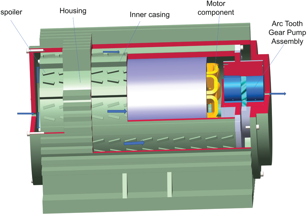
Figure 1: Schematic diagram of motor pump structure
The spoiler refers to a small protrusion, rib, guide vane or eddy current generator installed on the inner wall of the fan-shaped cooling channel of the motor pump housing or suspended in the channel. Its main purpose is to change the flow state of the hydraulic oil in the fan-shaped direct current channel, induce turbulence and secondary flow, and at the same time increase the heat exchange area.
When comparing different turbulence structures in the fan-shaped DC channels of the motor pump housing, the same blocking rate (also known as blocking ratio or area contraction rate) must be controlled. The same blocking rate is set to ensure that the spoiler of different structures cause the same initial obstruction to the flow passage. At the same flow resistance starting point, their heat transfer performance and flow resistance characteristics are compared. If comparisons are made under different blocking rates, performance differences may result from size rather than the structure itself, leading to distorted conclusions. The blocking rate is defined as the percentage of the projected area of the turbulence structure in the flow direction to the cross-sectional area of the flow passage.
There are various structural design schemes for the spoiler. For different structural forms of the spoiler, comparative analysis is conducted through COMSOL simulation calculations to compare the advantages and disadvantages of different structural forms. The shape of the cooling flow path of the motor housing is a fan shape. To facilitate the comparative analysis, the control flow sheet has the same length L, maximum width S, and the height of the spoiler is all 3 mm, ensuring that the projected area in the axial and radial directions of the motor is consistent. The structural forms are shown in Fig. 2.
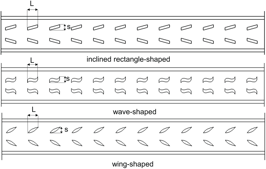
Figure 2: Schematic diagrams of three types of spoiler structures
2.3 COMSOL Numerical Calculation Method
To solve the steady-state temperature rise and temperature distribution of the new type of arc gear hydraulic motor pump, a multi-physical field numerical model including electromagnetic field, fluid field and temperature field is established. Electromagnetic field calculation is used to determine the electromagnetic loss generated during operation. This part ignores the influence of fluid and temperature fields on the electromagnetic field and adopts a unidirectional coupling method to load the electromagnetic loss as a heat source into the fluid and temperature field. The fluid and temperature field involves heat exchange between the fluid domain and the solid domain. It is solved by using the fluid-solid coupling heat transfer method, and its control equations include:
Fluid domain:
continuity equation:
In the formula:
In the formula:
In the formula:
In the formula:
In the formula:
In the formula:
This section elaborates on the system of control equations on which the simulation is based. The model is based on the fundamental laws of fluid mechanics and heat transfer, including the continuity Eq. (2) that describes the conservation of mass, the Navier-Stokes Eq. (3) that describes the conservation of momentum, the energy conservation Eq. (4), and the standard k-ω model (5) for simulating turbulence. Solid domain heat transfer is controlled by the heat conduction Eq. (6), and the fluid-solid coupling boundary is coupled through conditions (7)–(9).
Explanation of the reliability of the simulation method: The core of this study lies in solving the fluid-solid coupling heat transfer problem within the motor pump. Its reliability is based on the accurate setting of governing equations, boundary conditions, and material properties. The mathematical models used (such as the continuity equation, Navier-Stokes equation, energy equation, and the standard k-ω turbulence model) are the common basis for computational fluid dynamics and heat transfer. Although this study is solved using the COMSOL Multiphysics software, the effectiveness of the fluid-solid coupling heat transfer method applied in this study has been widely verified in similar problem research.
For example, Ji et al. [8] conducted simulations for a structurally similar hydraulic motor pump using a fluid-solid coupling heat transfer model based on ANSYS Fluent, and verified the temperature field prediction results through thermocouple experiments, with the maximum error within 10%. The study proved that for the fluid-solid coupling heat transfer problem of hydraulic motor pumps, the above control equations and modeling methods are reliable. This study strictly followed the same physical field description and modeling principles, only differing in the solver implementation. Mainstream commercial CFD software (such as ANSYS Fluent and COMSOL) have good consistency in solving such multi-physics field problems. Therefore, the simulation results in this study are reliable in revealing temperature distribution patterns and conducting scheme comparisons.
2.4 COMSOL Simulation Parameter Settings
When establishing the COMSOL multi-physics simulation model for this simulation, in order to balance the computational efficiency, the geometric structure was reasonably simplified, and the heat dissipation fins on the shell surface were ignored. The internal windings of the motor were simplified by equivalent blocks. The simulation model is shown in Fig. 3.
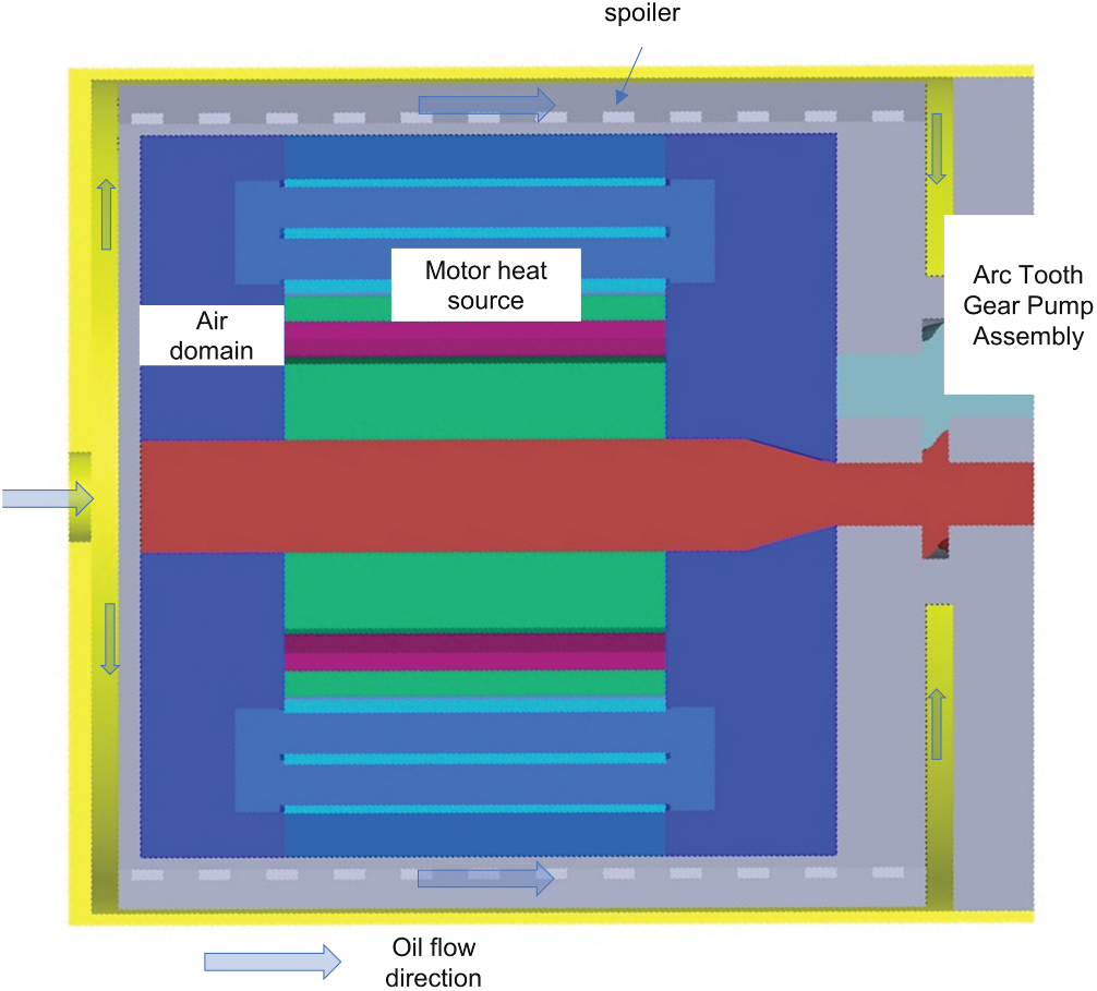
Figure 3: COMSOL simulation model diagram
To simplify the calculation, and since the subsequent strengthening of the cooling effect mainly targets the motor part, this study does not consider the flow field and heat source of the gear pump part. It only considers the motor part.
This research focuses on the heat dissipation enhancement mechanism of the motor part. This simplification is based on two considerations: First, the main heat of the gear pump is directly discharged from the system with the high-pressure oil, making a relatively small contribution to the steady-state temperature of the motor cavity. The core of this study lies in comparing the relative performance of different spoiler structures under the same boundary. Ignoring the common condition of the pump heat source, although it makes the absolute temperature value slightly ideal, does not affect the fair comparison of the heat transfer and flow resistance characteristics of each scheme, ensuring the validity of the mechanism analysis. The complete and systematic thermal coupling will be the focus of subsequent work.
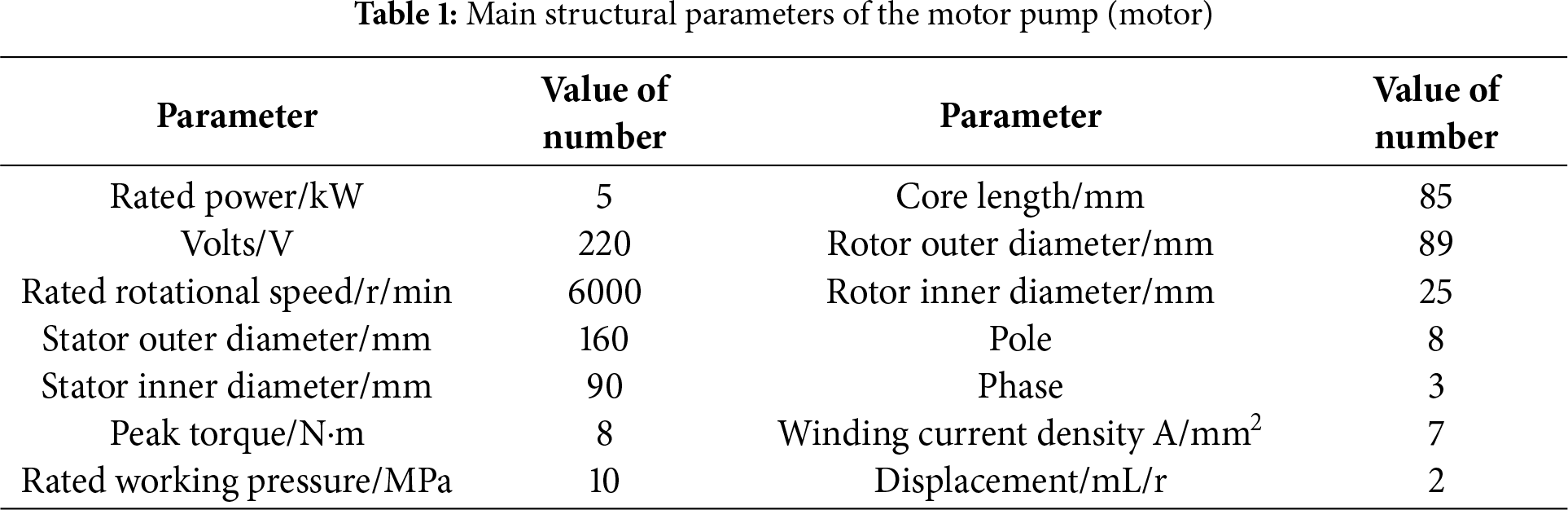
The main structural parameters of the motor pump are listed in Table 1, The losses of the permanent magnet synchronous motor mainly include copper loss of the winding, iron loss of the core, and eddy current loss of the permanent magnet. The formula for calculating the heat source intensity is:
Based on the structural parameters of the motor pump, a two-dimensional simulation model of the motor was established in ANSYS Maxwell. The transient solution module was selected, and the simulation time and step size were set. The electromagnetic losses of each part of the motor pump under the rated working condition are shown in Table 2 as follows Table 3.
In COMSOL, the rotating area is simulated using dynamic mesh and deformed geometry. According to the actual working conditions, the oil inlet is set as a pressure inlet (with a pressure of 0 Pa and an oil temperature of 20°C), and the outlet is set as a mass flow outlet (the flow rate is calculated based on the pump’s displacement, rotational speed, and oil density), with an outlet mass flow of 0.1544 kg/s. In COMSOL, the heat source intensity of each loss component of the motor is set according to the motor loss values in Table 2. Set the material properties of each component according to Table 3.
To reduce the influence of grid quality on the accuracy of the calculation results, this study conducted a grid independence verification. Two indicators that are important for heat dissipation and flow resistance performance were selected as monitoring variables: the maximum temperature of the stator and the pressure loss in the flow channel. Eight sets of different grid schemes were set up for calculation, with the range of grid node numbers being from 760,000 to 7,800,000. The analysis showed that as shown in Fig. 4. When the number of grid nodes reached 3.230000, further increasing the grid density had a relatively small impact on the maximum temperature of the stator and the pressure loss in the flow channel, which could meet the requirements for calculation accuracy. To balance the calculation efficiency and accuracy, all subsequent simulations in this study adopted a grid method with the same density as 323 million.
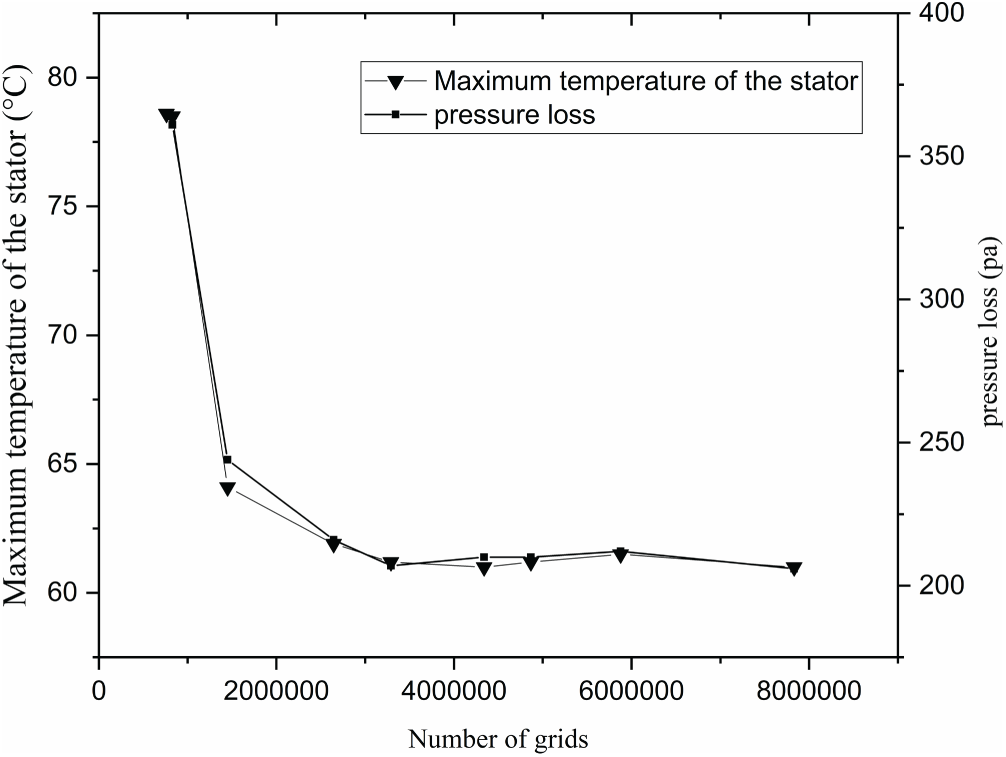
Figure 4: Grid independence verification curve
2.5 Comprehensive Evaluation Criteria for Heat Exchange Enhancement
To quantitatively evaluate the comprehensive performance of different turbulence control sheet structures, this study employs the Performance Evaluation Criterion (PEC) for comparative analysis. PEC is an authoritative indicator in the field of enhanced heat transfer [15] and its definition is:
PEC > 1 indicates that the comprehensive performance of this scheme is superior to the benchmark case. Given the complexity of the flow field and thermal field within the motor pump, it is cumbersome to directly obtain the precise average Nu and f values of the entire flow channel. Under the premise that the cooling medium, inlet temperature and mass flow rate in this study are strictly consistent, the following reasonable simplification can be made:
On the heat transfer side: For a flow channel with a fixed geometry, the total heat transfer quantity Q is directly proportional to the average convective heat transfer coefficient h (Q ∝ h), and h is directly proportional to Nu (h ∝ Nu). Therefore, the relative heat transfer intensity can be approximated as:
The increase ratio of the total heat exchange of the system
Flow resistance side: According to Darcy’s formula ΔP = f(L/D)(ρu2/2), under the same flow rate (i.e., the same flow velocity u) and the same flow channel geometry (L and D remain unchanged), the relative change in the friction factor can be directly reflected by the relative change in pressure drop:
3.1 Thermal Characteristics Analysis of Multi-Physical Field Coupling in Motor Pumps
The thermal performance of the motor pump housing was evaluated under natural air cooling, forced air cooling (with a wind speed of 2.5 m/s), and liquid cooling. As shown in Fig. 5 the maximum housing temperatures were 306°C, 196°C, and 27°C, respectively. The liquid cooling method achieved a dramatic reduction, lowering the peak temperature by approximately 91% compared to natural air cooling and 86% compared to forced air cooling.
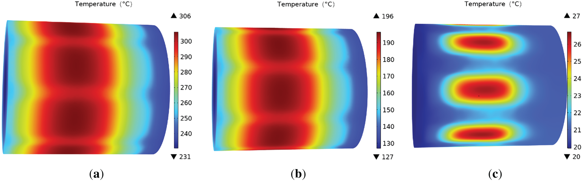
Figure 5: The temperature of the motor pump housing under three cooling methods. (a) natural air cooling; (b) forced air cooling (with a wind speed of 2.5 m/s); (c) liquid cooling
Fig. 6 shows the temperature cloud map of each heat source component of the motor pump without the flow guide vane. The stator has a relatively low average temperature due to direct heat conduction with the shell. The temperature of the stator yoke is lower than that of the teeth. The highest temperature occurs in the area where the stator teeth contact the air gap. This is because this area not only directly contacts the air gap but also receives radiant heat from the permanent magnet and the rotor. Therefore, the temperature of the stator teeth is the highest. The highest temperature of the stator winding (55.6°C) is located at the end of the winding, and the lowest temperature (52.9°C) is in the middle. This is because the heat in the middle can be dissipated through the rotor, while the end is in contact with air that has poor thermal conductivity, resulting in poor heat dissipation. The rotor and permanent magnet show a distribution pattern of higher temperature in the middle and lower temperature at both ends. Their temperatures are higher than those of the stator and winding. This is because the heat of the latter is mainly carried away by the oil in the flow channel, while the former mainly dissipates heat through convection with the air, which is less efficient.
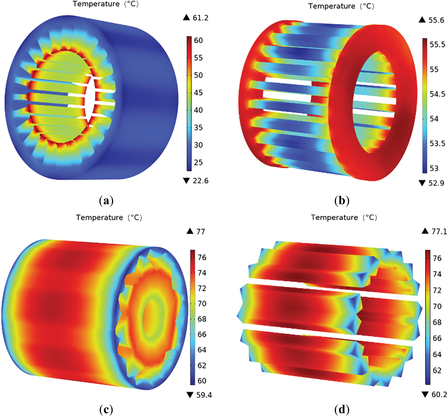
Figure 6: Temperature distribution characteristics of each component during the non-irradiation chip fabrication process. (a) stator; (b) winding; (c) rotor; (d) permanent magnet
The simulation results show that the liquid cooling method can effectively reduce the overall temperature of the motor pump. To further enhance the liquid cooling heat dissipation efficiency, this paper will next explore the enhanced heat dissipation scheme of installing turbulence plates in the shell flow channel.
3.2 Comparison of Heat Dissipation Performance of Different Spoiler Structures
To facilitate the observation of the flow field characteristics of the direct current channel part of the shell after adding the spoiler, the cross-section at a distance of 2 mm from the bottom surface of the flow channel in the fan-shaped direct current channel of the shell was captured in the COMSOL software, and the influence of different spoiler structures on the flow field characteristics was compared. As shown Fig. 7, when no flow deflectors were added, the streamlines were all smooth DC lines, and the hydraulic oil was in a stable laminar flow state within the shell’s DC section, with no obvious high-speed erosion zone or low-speed stagnation zone. The near-wall thermal boundary layer was relatively thick, which was not conducive to heat conduction. After adding the flow deflectors, due to the significant increase in flow resistance, the average flow velocity within the flow channel was lower compared to the baseline case without flow deflectors. However, the flow deflectors greatly promoted the turbulence of the flow. The strong pulsation and mixing in the flow field became the dominant factor for enhanced heat transfer. All three spoilers could to some extent change the flow field characteristics, but the disturbance effects were different. Among them, the wave-shaped and inclined rectangular flow deflectors caused the streamlines to undergo significant bending, which could draw the low-temperature main body to the vicinity of the high-temperature wall. The wing-shaped flow deflectors produced a small low-speed wake zone at the tail, and the disturbance was relatively weak.
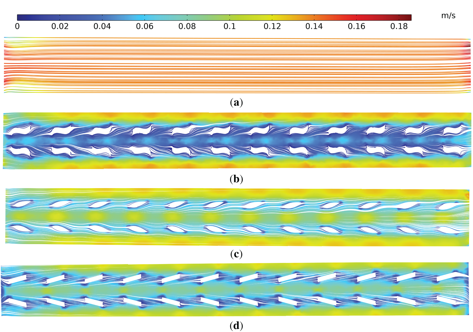
Figure 7: Streamline characteristics. (a) no spoiler; (b) wave-shaped; (c) wing-shaped; (d) inclined rectangle-shaped
Vorticity is a measure of the rotational motion of a fluid. The magnitude of the vorticity value can reflect the intensity of the vortices in the flow field and the degree of rotation of the fluid micro-tubes. It is a key parameter for analyzing the characteristics of turbulence and the mechanism of heat transfer enhancement [16]. To investigate the spatial distribution characteristics of vortices in different turbulence plates, the vorticity contour maps within the fan-shaped direct-flow channels of the shell were extracted in COMSOL. As shown in Fig. 8, without the t spoiler structure, there was no obvious vorticity value in the direct-flow channel. After adding the spoiler, certain vortical structures were generated. The wave-shaped spoiler can produce a wider vorticity area, which is consistent with the generation of higher turbulent kinetic energy. The oblique rectangular vorticity has a stronger directionality and can effectively guide the low-temperature fluid of the main flow towards the high-temperature wall. The wing-shaped structure also produced a strong vorticity, but its intensity and range were significantly weaker than the previous two structures, and the enhanced heat transfer capacity was relatively limited.
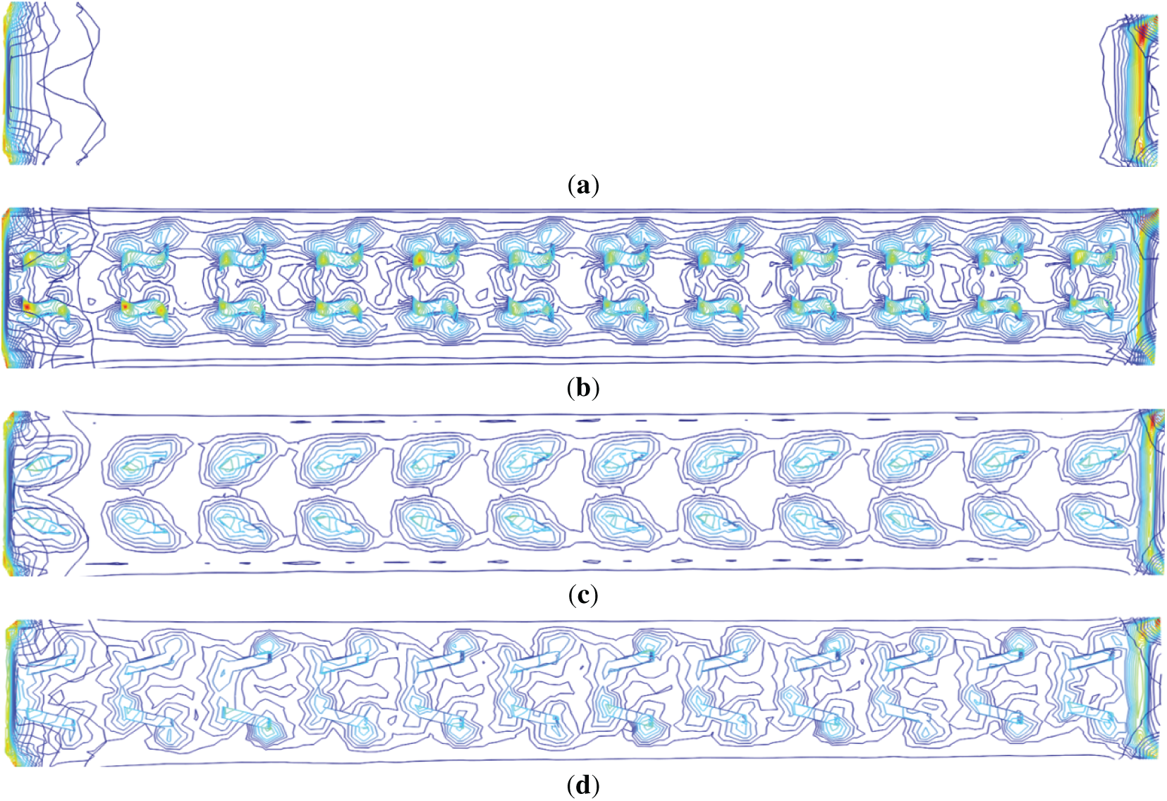
Figure 8: Vorticity contour map. (a) no spoiler; (b) wave-shaped; (c) wing-shaped; (d) inclined rectangle-shaped
In COMSOL, a central line is drawn along the direction of hydraulic oil flow within the shell flow channel, and the vorticity data of each scheme on this line are extracted for comparison. The intensity of the vorticity and the length of the maintaining distance directly determine the disturbance ability of the flow field and the effectiveness of enhancing heat transfer. As shown in Fig. 9, by observing the size of the vorticity at this straight line, the pattern of the vorticity size within the flow channel can be indirectly obtained. The peak points of each curve correspond to the most intense flow separation at the trailing edge of the spoiler and the core area where the vortex is initially rolled up. In this study, the overall vortex level of the wave-shaped structure is relatively strong, and the vortex level of the inclined rectangle is slightly stronger than that of the wing shape. Since this data is on a straight line, combined with the figure above, it can be known that the vortex intensity level of the wing shape is moderate but has poor diffusion. This conclusion is consistent with the subsequent analysis of turbulent kinetic energy and temperature field results, and jointly reflects the intrinsic flow mechanism of the performance differences of different spoiler.
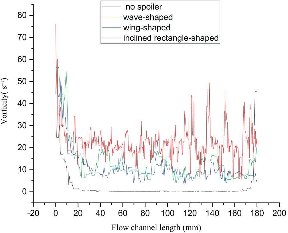
Figure 9: Vorticity distribution of different structures at the same straight line
Turbulent kinetic energy is an indicator for measuring the intensity of flow pulsation and directly affects the heat transfer efficiency [17]. To analyze the influence of different turbulence diffuser schemes on the distribution of turbulent kinetic energy, a straight line was taken from the center of the fan-shaped direct current channel along the shell in COMSOL, and the turbulent kinetic energy data of each scheme on this straight line was extracted. As can be seen from Fig. 10, when there is no spoiler, the turbulent kinetic energy only flows in the direction of the inlet and outlet of the direct current channel and is relatively high, and it quickly decays within the direct current channel. After adding the spoiler, the turbulent kinetic energy in the shell direct current channel always remains at a high level and can be sustained continuously, indicating that the flow pulsation has been enhanced, which is the direct cause of heat transfer enhancement.
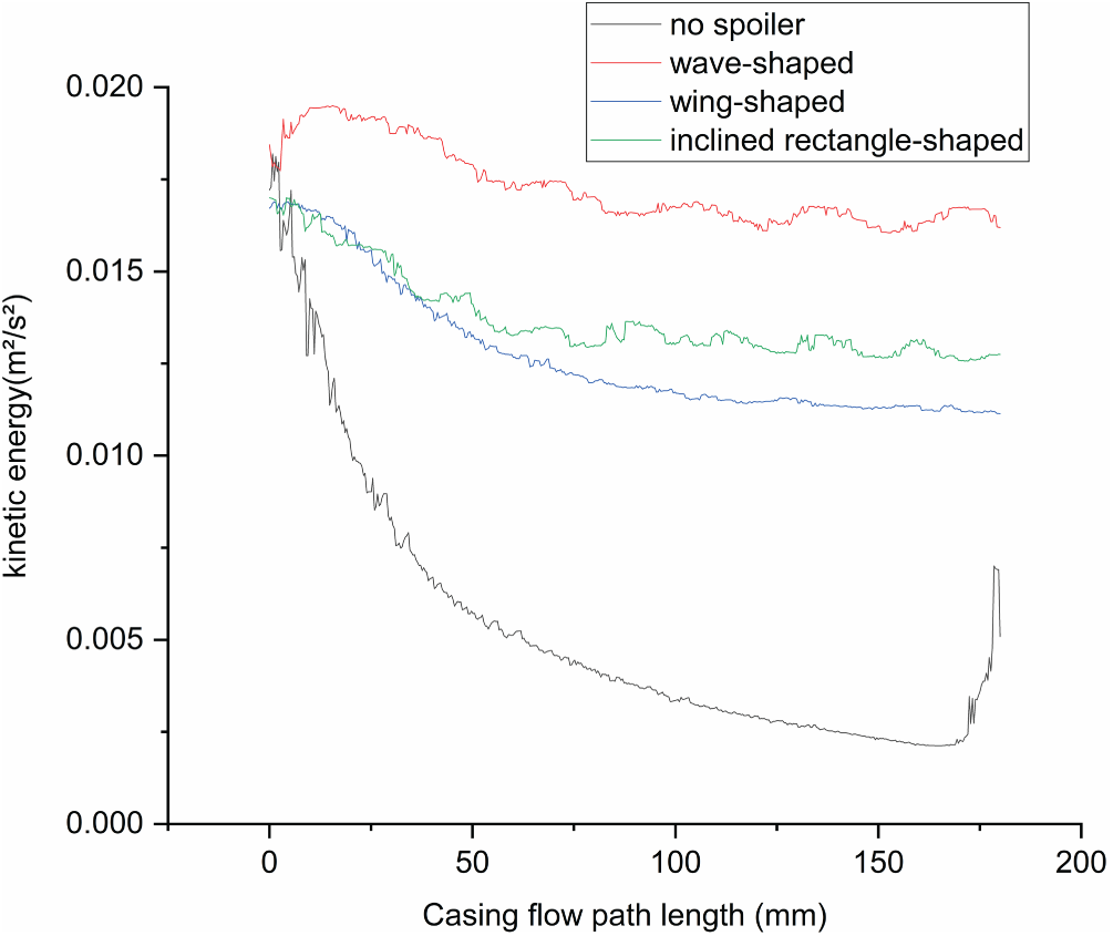
Figure 10: Turbulent energy distribution along the centerline
In COMSOL, simulations were conducted on the maximum temperatures of each component of the motor pump and the pressure loss within the fan-shaped DC channels of the shell in different fin structures. The results are shown in Fig. 11. All three spoilers can enhance the heat transfer efficiency and increase the pressure loss in the shell flow channels. Among them, the wave-shaped spoiler has the highest heat transfer efficiency, but also the largest pressure loss. The inclined rectangular spoiler has a relatively balanced heat transfer capacity and pressure loss. The wing-shaped spoiler only slightly improves the heat dissipation efficiency. Due to the poorer heat dissipation effect of the wing-shaped spoiler compared to the other two, the maximum temperature of the stator under the wing-shaped spoiler also decreases less. The main reason is that the wing-shaped structure increases the heat exchange area of the flow channel relatively little and has poorer fluid disturbance. The turbulent kinetic energy and vorticity of the wave-shaped scheme are relatively large, but the final steady-state temperature of the system is close to that of the inclined rectangular scheme. This is mainly because the bottleneck of the heat dissipation performance of this system mainly lies in the internal thermal conduction resistance. When the convective heat transfer is strengthened to a certain extent, the rate of heat conduction from the internal motor heat to the shell has become a limiting factor. At this point, further increasing the intensity of convective heat transfer has no obvious effect on reducing the temperature of the motor components, but causes a large pressure loss. It is particularly important to note that the performance evaluation of this study is based on a fixed flow condition, which is suitable for comparing the relative performance of different spoilers. In actual hydraulic systems, an increase in flow resistance will lead to a decrease in flow rate. The actual heat transfer performance of the wave-shaped spoiler needs to be further evaluated in combination with the flow-pressure characteristics of the system.
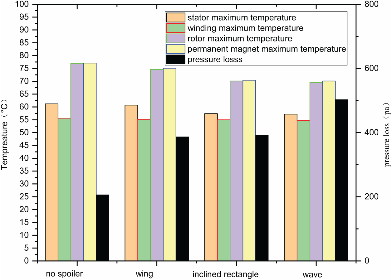
Figure 11: Analysis of pressure loss and maximum temperatures of each component
Comprehensive performance evaluation
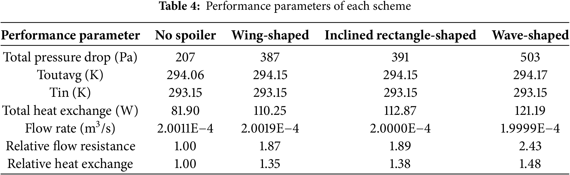
Based on the comprehensive heat transfer evaluation indicators mentioned in 2.5, macroscopic physical quantities such as total heat transfer and total pressure drop (from the motor pump inlet to the outlet of the shell’s direct current channel) were directly extracted from the fluid-solid coupling heat transfer simulation results of each scheme. The performance parameters of each scheme are shown in Table 4.
Under the condition of a fixed flow rate, as evaluated by the PEC criterion shown in Fig. 12, the inclined rectangle-shaped PEC has the highest value (1.114), indicating that its comprehensive effect is the best. The values of wing-shaped and wave-shaped PEC are close, but the wave-shaped pressure loss is relatively large and its comprehensive performance is poor.
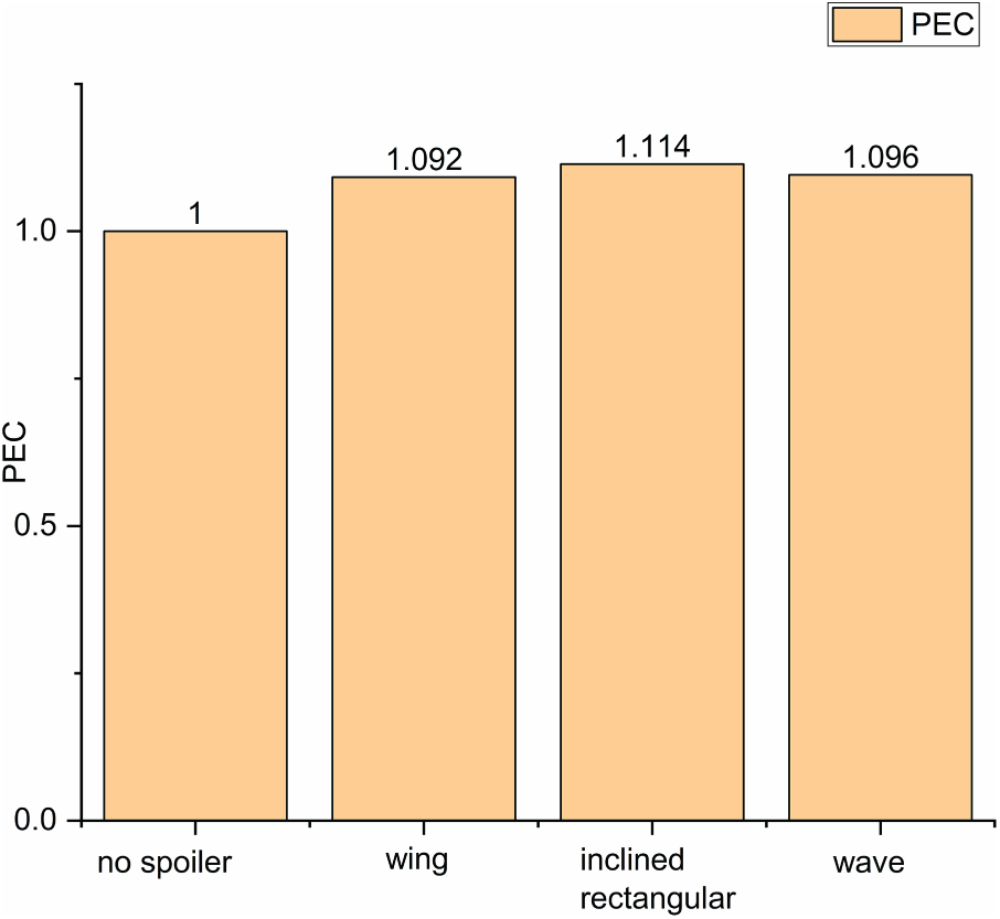
Figure 12: Comparison results of PEC values
Taking into account the improvement of heat dissipation, system energy consumption, and flow field characteristics, the inclined rectangular spoiler is the best choice for achieving a balance between heat dissipation performance and flow resistance cost. It is recommended for use in most hydraulic motor pump applications. The wave-shaped type has a relatively strong heat transfer capacity, but it has a large pressure loss. The wing-shaped performs reasonably under the PEC criterion, but its cooling effect on the key internal parts of the motor is weaker than that of the inclined rectangle. The main reason is that the airfoil structure only increases the heat transfer area in the flow channel, and has a poor effect on disturbing the hydraulic oil in the shell flow channel, with low levels of vorticity and turbulent kinetic energy. The overall performance is not good. From the perspective of engineering application, the heat dissipation enhancement brought by the inclined rectangular spoiler (with the total heat exchange increasing by approximately 38%) has direct practical value. Firstly, the significant reduction in the operating temperature of permanent magnets and windings can effectively delay insulation aging and lower the risk of high-temperature demagnetization of permanent magnets, directly enhancing the operational reliability and service life of motor pumps under rated and harsh working conditions. More importantly, under the premise of maintaining the same maximum temperature limit, the enhanced heat dissipation capacity makes it possible for the motor to withstand higher current density. This means that the motor pump is expected to achieve higher instantaneous torque or continuous power output without increasing its volume, thereby expanding its working performance boundary. Therefore, this optimization not only improves local heat transfer but also provides crucial thermal management support for enhancing the power density and overall performance of the motor pump.
Engineering application and cost-benefit analysis:
To evaluate the engineering value of the proposed scheme, a brief analysis is conducted from the aspects of manufacturing cost and performance benefit.
In terms of manufacturing costs, the inclined rectangular and airfoil spoilers have a simple structure and are suitable for one-piece molding with aluminum alloy or cast iron shells through casting processes, with almost no additional costs. Wavy structures have relatively high processing difficulty and cost due to their complex shapes.
In terms of performance benefits, the inclined rectangular spoilers can increase the total heat exchange by approximately 38%, significantly reduce the temperature of the permanent magnets and windings, which helps to extend the service life and enhance the reliability of the system under harsh operating conditions. Meanwhile, the enhanced heat dissipation capacity makes it possible to increase the motor power density under the same temperature rise limit, which is conducive to the miniaturization and lightweight design of the equipment. Although the channel pressure loss will increase by approximately 89% accordingly, this cost is acceptable for high-end applications that prioritize reliability.
In conclusion, the inclined rectangular spoiler achieves the best balance among heat dissipation performance, flow resistance cost and manufacturing cost, providing an efficient, economical and easy-to-implement solution for the engineering thermal management enhancement of motor pumps.
This study focuses on the heat dissipation issue of the new arc-shaped gear hydraulic motor pump. Using COMSOL, a fluid-solid coupling simulation model was established to conduct a comprehensive research from the basic thermal characteristic analysis to the design analysis of enhanced heat dissipation schemes. The main research contents are as follows:
(1) A fluid-solid coupling heat transfer simulation model for the motor pump was established: Through grid independence verification, the calculation accuracy was ensured. The complex multi-physics field heat transfer process inside the motor pump was simulated, providing a means for subsequent heat dissipation scheme research. The temperature distribution law of the arc-shaped gear hydraulic motor pump was revealed: The high-temperature areas were concentrated in the rotor and permanent magnet parts, and the stator tooth part and the air gap contact became the highest stator temperature point due to comprehensive heating. The study confirmed that the liquid cooling method can reduce the maximum temperature of the housing by more than 83% compared to air cooling.
(2) A design criterion for the fan-shaped DC channel internal spoilers based on the unified blocking rate was proposed: Taking the blocking rate as the control variable, it ensured the fairness of different spoiler structures comparison, providing a reference method for similar studies. The strengthening heat dissipation mechanism and performance characteristics of different spoiler structures were clarified. It was found that the wave-shaped spoiler generated the strongest vorticity, but the flow channel pressure loss was the greatest. The inclined rectangle-shaped spoiler can guide the fluid impact on the wall in a directional manner, achieving the best balance between heat transfer improvement and flow resistance increase, while the wing-shaped spoiler has relatively poorer comprehensive effect. A comprehensive evaluation system for heat transfer performance and system energy consumption was established: Through the PEC criterion evaluation: Comprehensive analysis shows that the inclined rectangular spoiler not only has the best comprehensive performance in heat transfer and flow resistance (PEC = 1.114), but also its structure is the easiest to be integrally formed through shell casting, with almost no increase in manufacturing cost. This solution can effectively reduce the temperature of the high-temperature components inside the motor, which is expected to enhance the operational reliability of the system under harsh working conditions or expand its power density without increasing the volume. Therefore, the inclined rectangular spoiler achieves the best balance among heat dissipation performance, flow resistance cost and manufacturing cost, providing an efficient and easy-to-implement solution for the engineering thermal management enhancement of motor pumps.
Although adding turbulence structures in the liquid-cooled flow channel is an effective heat transfer enhancement technology, it is not common in existing commercial motor pumps. The main reasons are: The traditional design of motor pumps often addresses temperature rise by increasing the heat dissipation area (such as reinforcing the casing) or adopting more thorough cooling methods like oil-impregnating the stator. Although these approaches may increase volume or process complexity, they are more intuitive in design and the risks are controllable. Integrating the spoiler into the narrow shell flow channel poses higher requirements for the precision of the casting process, and its benefits need to be carefully weighed at the system level. This study points out that the inclined rectangular spoiler, due to its simple structure and ease of one-piece casting, has achieved the best balance in terms of performance, cost and process feasibility, providing a clear path for the engineering application of this technology. The key to its commercial application lies in the integrated design with the shell and the optimization of the spoiler as a core component of the thermal management system during the product development stage, thereby significantly enhancing the power density and thermal reliability of the product at the lowest additional cost.
Acknowledgement: The authors would like to sincerely thank Henan University of Science and Technology for providing laboratory facilities support and financial support. The scientific calculations in this paper have been done on the HPC Cloud Platform of the Henan Collaborative Innovation Center for Advanced Manufacturing of Mechanical Equipment.
Funding Statement: The research is supported by the Henan Provincial Key Research and Development Special Project (251111220200), Natural Science Foundation of Henan Province Project (252300420446).
Author Contributions: Geqiang Li: Writing—review & editing, Writing—original draft, Project administration, Conceptualization. Shuai Wang: Writing—original draft, Methodology, Formal analysis, Data curation. Kai Wang: Writing—original draft, Visualization, Investigation. Juntao Liu: Writing—original draft, Supervision, Resources. Zhengyang Han: Writing—original draft, Validation, Software. Donglin Li: Writing—review & editing, Visualization. All authors reviewed the results and approved the final version of the manuscript.
Availability of Data and Materials: Data can be provided on request.
Ethics Approval: Not applicable.
Conflicts of Interest: The authors declare no conflicts of interest to report regarding the present study.
Nomenclature
| The projected area (i.e., the shadow area) of the aerodynamic structure in the direction of flow, m2 | |
| The cross-sectional area of the flow channel (when there is no disturbance structure), m2 | |
| Density of the fluid, kg/m3 | |
| Velocity, m/s | |
| Pressure, Pa | |
| Time, s | |
| Dynamic viscosity, Pa·s | |
| Fluid temperature, K | |
| Specific heat at constant pressure, J/(kg·K) | |
| Thermal conductivity of the fluid, W/(m·K) | |
| Viscous dissipation term, W/m3 | |
| Turbulent kinetic energy, m2/s2 | |
| The specific dissipation rate, 1/s | |
| Turbulent kinetic energy generation term, m2/s3 | |
| Solid density, kg/m3 | |
| Specific heat capacity of the solid, J/(kg·K) | |
| VoluMetric heat source, W/m3 | |
| Thermal conductivity of the solid, W/(m·K) | |
| Normal temperature gradient at the interface, K/m | |
| Winding current, A | |
| Winding resistance, Ω | |
| Represents the copper volume, m3 | |
| Iron loss coefficients | |
| Power supply frequency, Hz | |
| Amplitude of the magnetic flux density, T | |
| Average Nu number and the friction factor, respectively | |
| Reference for a disturbance-free flow plate | |
| ΔP | The increase ratio of the total pressure drop, Pa |
| Q | The total heat exchange through the flow channel wall, W |
References
1. Yang HY, Pan M. Engineering research in fluid power: a review. J Zhejiang Univ Sci A. 2015;16(6):427–42. doi:10.1631/jzus.a1500042. [Google Scholar] [CrossRef]
2. Huang C, Xu K, Wei Z, Li G. Numerical simulation of factors affecting flow characteristics of double-circular-arc gear pump. Food Mach. 2023;39(10):87–92,111. [Google Scholar]
3. Zappaterra F, Pan D, Ransegnola T, Vacca A, Sudhoff SD, Busquets E. A novel electro-hydraulic unit design based on a shaftless integration of an internal gear machine and a permanent magnet electric machine. Energy Convers Manag. 2024;310:118432. doi:10.1016/j.enconman.2024.118432. [Google Scholar] [CrossRef]
4. Heitzig S, Sgro S, Theissen H. Energy efficiency of hydraulic systems with shared digital pumps. Int J Fluid Power. 2012;13(3):49–57. doi:10.1080/14399776.2012.10781060. [Google Scholar] [CrossRef]
5. Liu Y, Li Y, Chen Z, Wang C, Xing Z. Numerical research on refrigerant injection for motor cooling of screw compressor for heat pump with large temperature lift. Appl Therm Eng. 2024;253(1):123837. doi:10.1016/j.applthermaleng.2024.123837. [Google Scholar] [CrossRef]
6. Zhang ZY, Gao DR, Xu SH, Sun YN, Zhang Y. Numerical simulation analysis and optimization of temperature field of high speed motor pump. J Chongqing Univ Technol Nat Sci. 2020;34(12):111–20. [Google Scholar]
7. Bai GC, Zhao HQ. Study on influence of cooling channel structure on temperature rise of motor pump. J Zhengzhou Univ Eng Sci. 2021;42(4):53–7. [Google Scholar]
8. Ji H, Xing HH, Sun F, Peng YB, Li C. Temperature field characteristics of hydraulic motor pumpbased on fluid-structure coupling heat transfer analysis. Chin Hydraul Pneum. 2023;47(3):1–8. [Google Scholar]
9. Li YX, Wang X, Zhang J, Zhang L, Wu JH. Comparison and analysis of the arrangement of delta winglet pair vortex generators in a half coiled jacket for heat transfer enhancement. Int J Heat Mass Transf. 2019;129:287–98. doi:10.1016/j.ijheatmasstransfer.2018.09.109. [Google Scholar] [CrossRef]
10. Zhu J, Wang J, Cheng D, Mao J, Zhang K. Numerical investigation and parameter optimization on a rib-grooved liquid-cooled plate for lithium battery thermal management system. J Energy Storage. 2024;85:111085. doi:10.1016/j.est.2024.111085. [Google Scholar] [CrossRef]
11. Majmader FB, Hasan MJ. Effects of bidirectional rib arrangements on turbulent flow structure and heat transfer characteristics of a two-pass channel for turbine blade internal cooling. Int Commun Heat Mass Transf. 2024;156:107688. doi:10.1016/j.icheatmasstransfer.2024.107688. [Google Scholar] [CrossRef]
12. Peng Z, Huang J, Lv J, Ye J. Multi-objective optimization of cold plate with spoiler for battery thermal management system using whale optimization algorithm. Appl Therm Eng. 2025;260:124974. doi:10.1016/j.applthermaleng.2024.124974. [Google Scholar] [CrossRef]
13. Hao JX, Tang ZG, Li HQ, Jiang C. Optimal design of the spoiler in cooling channel of liquid-cooled motor. J Hefei Univ Technol Nat Sci. 2016;39(4):5. [Google Scholar]
14. Wang KP, Lei YZ, Gou L, Wang YJ, Han YL, Sheng H, et al. Optimization design on enhanced heat transfer of medium-deep coaxial casing heat exchanger. Sci Technol Eng. 2025;25(25):10870–80. [Google Scholar]
15. Li ZM, Zhang XL, Li Y, Zhou H, Qiu YH. Heat transfer and flow characteristics of annular inner ribbed convex tubes. Sci Technol Eng. 2025;25(20):8498–507. [Google Scholar]
16. Zhao LX, Yu F, Xu BR, Jin Y, Jiang MH, Lu MM. Influence of rotation speed of screw pump on the flow field characteristics of oil-water cyclone separation pipe. China Pet Mach. 2024;52(7):98–106. doi:10.16082/j.cnki.issn.1001-4578.2024.07.013. [Google Scholar] [CrossRef]
17. Yang QS. Study on the flow and heat transfer enhancement characteristics in plate heat exchanger for space nuclear power systems. Nanjing Univ Aeronaut Astronaut. 2023;8:84. [Google Scholar]
Cite This Article
 Copyright © 2026 The Author(s). Published by Tech Science Press.
This work is licensed under a Creative Commons Attribution 4.0 International License , which permits unrestricted use, distribution, and reproduction in any medium, provided the original work is properly cited.
 Downloads
 Citation Tools