
 Submit a Paper
 Propose a Special lssue
 Open Access
ARTICLE

Simulation and Optimization of Urban Small-Scale Centralized Bio-Gas Purification Process Based on Methyl Diethanolamine Absorbent
1 China Shenzhen Gas Corporation Ltd., Shenzhen, 518040, China
2 School of Chemistry and Chemical Engineering, South China University of Technology, Guangzhou, 510640, China
3 School of Science and Engineering, The Chinese University of Hong Kong, Shenzhen, 518172, China
* Corresponding Authors: Hengrong Zhang. Email: ; Dongxu Ji. Email:
; Shuanshi Fan. Email:
Frontiers in Heat and Mass Transfer 2026, 24(1), 8 https://doi.org/10.32604/fhmt.2026.075692
Received 06 November 2025; Accepted 31 December 2025; Issue published 28 February 2026
 View Full Text
 Download PDF
Abstract
This study addresses the energy-intensive challenge of small-scale biogas upgrading by optimizing a chemical absorption process employing methyl diethanolamine (MDEA). Focusing on a typical distributed application of 300 Nm3/d, we developed an integrated simulation-optimization framework using Aspen HYSYS 14.0 to systematically evaluate the effects of critical operating parameters—absorption pressure, MDEA concentration, flow rate, temperature, number of trays, and reboiler duty—on methane purity and energy consumption. The key finding is the identification of an optimal parameter set: absorption pressure of 1200 kPa, MDEA concentration of 20 mol%, lean flow rate of 2.5 kmol/h, temperature of 298.15 K, 20 absorber trays, 10 regenerator trays, and a reboiler duty of 4 kW, which enabled the product gas to achieve a high CH4 concentration of 97 mol%, compliant with pipeline standards. A detailed energy consumption analysis revealed that the reboiler is the most energy-intensive unit, accounting for 75.40% of the total 5.29 kW energy consumption, followed by the gas compressor (23.38%). The specific energy consumption for CH4 recovery and the Energy Consumption Index (ECI) were quantified at 0.8852 kWh/kg CH4 and 6.82, respectively. This work provides a validated optimization strategy and critical energy breakdown, offering practical guidance for enhancing the technical and economic viability of small-scale, centralized biogas purification systems.Keywords
Biogas is a renewable energy source that offers an alternative solution to the world’s ever-growing energy demands, while also aiding in waste reduction and greenhouse gas (GHG) emissions [1]. It is considered carbon-neutral because the carbon in biogas originates from organic materials (feedstocks) that capture carbon from atmospheric CO2 over a relatively short period [2]. In addition to CH4, biogas typically contains 25–45 mol% CO2 and trace amounts of volatile organic compounds [3–5]. CO2 is a persistent gas that reduces the density and calorific value of biogas [6]. To enhance the calorific value of raw biogas and improve its quality for more complex end uses, it is often necessary to reduce its CO2 content before utilization [7,8]. Currently reported biogas purification technologies include chemical absorption [9], pressure swing adsorption [10], cryogenic separation [11], membrane separation [1], and hydrate-based separation [12]. Compared to other technologies, chemical absorption offers advantages such as high absorption capacity per unit volume of absorbent and high gas purification efficiency, making it the leading biogas purification technology. However, it is also characterized by high energy consumption for heating the rich absorbent during regeneration [13]. When using amines for chemical absorption, the chemical reactions exhibit strong selectivity, resulting in methane (CH4) losses below 0.1% and achieving methane concentration of 99% [14,15]. Typical operating parameters include a temperature of 120°C and a pressure of 1–2 bar [16]. However, due to evaporation necessary in the process, some amine solution is lost and requires replacement [17]. Separating CO2 from the regenerated solution is achieved through steam heating, which returns CO2 to the gas phase, involving significant energy consumption [18]. Some authors have achieved nearly 30% reduction in energy consumption while achieving 90% CO2 capture efficiency [19]. The typical loading capacity of most amines is approximately 0.5–1.0 moles of CO2 per mole of amine [20]. In terms of consumption, water, electricity, and various compounds are required. Electricity consumption depends on the operational capacity of the unit, with minimum electricity consumption at maximum load approximately 0.12 kWh/Nm3/h, and maximum electricity consumption at minimum load approximately 0.14 kWh/Nm3/h. Furthermore, the desorption tower requires heat for amine regeneration, consuming approximately 0.55 kWh/Nm3/h of biogas [21]. The advantages of the chemical absorption process stem from CO2’s high selectivity towards amines, resulting in significantly reduced volume of absorbent solution. For instance, chemical absorption can dissolve CO2 in the range of 1 to 2 orders of magnitude per unit volume. On the other hand, overall energy consumption can be lower if any waste heat is available for the absorption stage compared to other scenarios [15].
Common alkanolamine solvents used for biogas decarbonization include monoethanolamine (MEA), diglycolamine (DGA), diethanolamine (DEA), aminoethylethanolamine (AEEA), and formulated or activated methyl diethanolamine (MDEA). Among these, MDEA has been widely recognized as an efficient and energy-saving CO2 absorbent for both biogas upgrading and natural gas sweetening, and it has been extensively adopted as a commercial-grade amine for CO2 capture [22]. Compared with primary and secondary amines (such as MEA and DEA), MDEA offers several significant advantages. Recent comparative studies further highlight that MDEA provides a favorable balance between absorption capacity and regeneration energy demand among common amine solvents [23]. Firstly, it features lower operational costs. According to the findings of Borhani and Wang [24], primary and cyclic amines typically exhibit high reaction enthalpy and faster reaction rates with CO2, while tertiary amines such as MDEA demonstrate higher absorption capacity and lower regeneration energy demand. Since solvent regeneration accounts for approximately 40%–60% of the total CO2 capture cost in chemical absorption processes [25], MDEA presents a clear advantage in terms of economic efficiency. In a comparative study by Zhu et al. [26], the CO2 absorption performance of four solvents—MEA, DEA, MDEA, and 2-amino-2-methyl-1-propanol (AMP)—was simulated under identical conditions using Aspen Plus. The results showed that MDEA offered the lowest operating cost, with an energy consumption of approximately 3 GJ per ton of CO2 removed. In addition, MDEA exhibits superior chemical stability. de Ávila et al. [27] conducted a comparative evaluation of the thermal and oxidative stability of MDEA, MEA, and DEA in CO2 capture processes. Their findings indicated that MDEA performed more stably under high temperature and high CO2 concentration conditions, showing particular resistance to both oxidative and thermal degradation when compared to MEA and DEA.
At present, in addition to extensive research on solvent selection, a significant body of work has focused on process optimization aimed at reducing energy consumption or improving CO2 capture efficiency. For example, Deng et al. [28] employed Aspen HYSYS simulation software to investigate the factors affecting CO2 removal from natural gas using amine-based solvents. Their study simulated the effects of variables such as the number of trays in the absorber, operating pressure, feed gas temperature, MDEA concentration, and amine formulation. The simulation results were systematically summarized and reasonably interpreted to deepen the understanding of the process behavior. In another study, Antonini et al. [29] developed a CO2 capture process based on MDEA using a combination of flowsheet modification and multi-objective optimization. Applied to a hydrogen production system from natural gas, the optimized process achieved a high CO2 capture rate of 99.8% while significantly reducing overall energy consumption. However, most of the existing research has primarily focused on large-scale applications, with limited attention to small-scale adaptability. In small-scale biogas upgrading scenarios, the absence of economies of scale often results in higher unit costs, making such systems economically less attractive [30]. Therefore, it becomes essential to compensate for scale-related disadvantages through operational parameter optimization, thereby enhancing the technical and economic feasibility of small-scale biogas purification systems [31].
In this study, focusing on small-scale urban centralized biogas (300 Nm3/d) as the simulation target, a chemical absorption process based on MDEA absorbent was utilized to investigate the impact of different process parameters on methane (CH4) concentration in the product and energy costs. Optimal operational parameters were selected to achieve CH4 concentration in the product gas meeting natural gas pipeline transportation standards. Detailed analysis of the overall process energy consumption was conducted, providing technical and theoretical support for the purification of small-scale centralized urban biogas in practical applications. The simulation-based optimization approach adopted here aligns with methodologies applied in recent amine-based capture studies [32].
The main contributions of this study are as follows:
(1) Research scale and context: This work focuses on a small-scale urban biogas purification system (300 Nm3/d), representing a typical distributed energy application, in contrast to conventional large-scale CO2 capture studies.
(2) Process optimization framework: An integrated optimization approach combining Aspen HYSYS simulation and Energy Consumption Index (ECI) analysis was developed to quantify the effects of key operating parameters—absorption pressure, MDEA concentration, flow rate, temperature, and reboiler duty—on methane concentration and total energy use.
(3) Energy consumption analysis: The study quantitatively identified the energy contribution of major process units (compressor, pumps, and reboiler) and proposed practical reduction strategies, such as waste heat recovery for solvent preheating.
Overall, the research expands current MDEA-based simulation studies by introducing a small-scale application focus, a quantitative optimization framework, and energy pathway analysis relevant to distributed biogas upgrading systems.
2 Process Construction and Research Methods
The process used Methyl Diethanol Amine (MDEA) solution as the gas absorption solvent (lean solution). According to the reaction mechanism between CO2 and the amine solution, it is known that the reaction is reversible. Higher pressures can promote the forward absorption reaction, increasing the absorption of CO2. The process simulation operated under the following assumptions [33]:
(1) The mole fractions of CH4 and CO2 in the feed gas were 67 mol% and 33 mol%, respectively.
(2) The initial temperature and pressure of the feed gas were 303.15 K and 110 kPa, respectively.
(3) The feed gas flow rate was 300 Nm3/d.
(4) The compressor had an efficiency of 85%.
(5) During the operation of both the absorption column and the regeneration column, a per-tray pressure drop of 0.25 kPa is assumed.
(6) The methane concentration in the product gas was 97 mol%.
The simulation was conducted using Aspen HYSYS 14.0 [34,35] to simulate and optimize the energy consumption and performance of the designed process. The gas–liquid reaction between CO2 and MDEA is assumed to reach thermodynamic equilibrium within each tray, which is a reasonable approximation under typical industrial operating conditions due to the fast reaction rate of CO2 with amines. Therefore, explicit kinetic parameters were not introduced. This assumption allows for reliable prediction of process performance and energy consumption, as validated by previous studies [26,28]. The feed biogas was simplified to a binary CO2/CH4 mixture, as trace components are typically removed by pretreatment and their inclusion is not central to the core CO2/CH4 separation mechanism studied here.
The absorption process consists of a gas compression unit, an absorption tower unit, and a desorption tower unit. The specific simulation flow is illustrated in Fig. 1. Biogas undergoes compression (Com-1, Com-2) and cooling (E-3, E-4) before entering the absorption tower unit (T1). The product gas, after the reaction, is discharged from the top ofT1, while the MDEA rich solution exits from the bottom of T1 and undergoes pressure reduction via a pressure control valve to 110 kPa. It then undergoes heat exchange with MDEA lean solution (E-1) before entering the desorption tower (T2) for regeneration of the absorbent solution. The regenerated MDEA lean solution is pumped (Pump-2), cooled (E-2), and returned to the absorption tower for further reaction. The desorbed CO2 (Rich CO2) is discharged from the top of T2. In this process, the amine loss in the desorption tower is relatively low; therefore, wash trays were not installed. To maintain the system amine balance, an amine makeup point was set in stream M9 to sustain absorption performance.
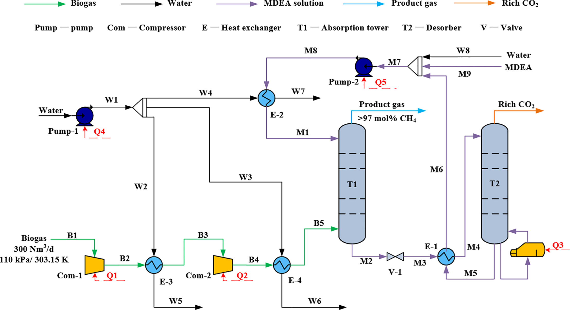
Figure 1: Process flow chart of biogas purification by absorption method
2.3 Energy Consumption Evaluation Index
2.3.1 Unit Recovery Energy Consumption
The specific energy consumption is a key performance indicator for evaluating the efficiency of gas purification processes. It is defined as the total energy consumption divided by the mass flow rate of the target gas in the product gas, as shown in Eq. (1) [33]:
where
From the second law of thermodynamics, it is known that the separation of a mixture of gases is a non-spontaneous process that requires external work to meet separation requirements. Assuming the separation process is an ideal reversible process, the corresponding work requirement is minimized, known as the minimum separation work [36]. The minimum separation work represents the theoretical limit of energy consumption in the actual separation process; a higher value indicates greater difficulty in gas separation. The minimum separation work is independent of the specific separation process and primarily influenced by parameters such as the concentration of components in the feed gas, concentration of products, and recovery rate. If the feed gas contains components A and B, which are separated into products Y and Z with a recovery rate of r, the minimum separation work required can be calculated using the following formula [37]:
In the equation,
2.3.3 Gas Separation Energy Consumption Index (ECI)
The minimum separation work is independent of the specific separation process, but different separation process routes require varying energy consumption to achieve the same separation objectives. To evaluate the economic viability of various separation processes, the Energy Consumption Index (ECI) is used, which compares the actual energy consumption of a process to its minimum separation energy requirement. Furthermore, within the same separation process, this ratio provides insight into deviations from the ideal separation process under different separation requirements, thereby guiding the optimization of industrial process flows. The Energy Consumption Index (ECI) is obtained by dividing the actual separation work by the minimum separation work, as shown in Eq. (3) [38]:
where
In the gas absorption process, factors such as operating pressure, absorbent concentration, flow rate, temperature, number of trays in the absorption tower, etc., significantly influence CO2 absorption efficiency and the composition of the product gas. Additionally, the reboiler load in the regeneration tower affects the regeneration of the absorbent. Therefore, optimizing operational parameters of the chemical absorption unit is essential to achieve high-concentration product gas and low energy consumption.
Higher pressure facilitated the reaction between CO2 and the methyldiethanolamine (MDEA) solution, but it also increased compression energy consumption and equipment costs. Therefore, it was crucial to determine the appropriate absorption pressure. For simulation purposes, an MDEA absorbent concentration of 20 mol% [24,26], a volumetric flow rate of 3 kmol/h, a plate tower with 20 trays [28], and an internal pressure drop of 5 kPa within the tower were assumed [33].
The absorption process was simulated using Aspen software. Fig. 2 illustrates the effects of operating pressure in the absorption column on CO2 absorption efficiency, methane (CH4) concentration, and product gas yield. As the absorption pressure increases, both CO2 absorption efficiency and CH4 concentration in the product gas rise markedly in the medium-pressure range, while the improvement becomes progressively less significant at higher pressures. At an absorption pressure of 200 kPa, the CH4 concentration in the product gas is 91.90 mol%, and the CO2 absorption efficiency is approximately 88%. When the pressure is elevated to 400 kPa, the CH4 concentration increases substantially to 96.03 mol%, accompanied by a clear enhancement in CO2 capture capacity. However, beyond this point, the rate of improvement declines significantly. At 600 kPa, the CH4 concentration reaches 96.81 mol%, and at 1100 kPa it increases marginally further to 97.31 mol%. Additional pressure increases yield only negligible gains in CH4 concentration while sharply increasing compression energy consumption. This trend is consistent with the findings of Zhu et al. [26] and Deng et al. [28], who simulated natural gas decarbonization using MDEA absorbents and reported that higher pressures substantially improve CO2 absorption efficiency and CH4 purity. These results indicate that moderate pressures can effectively enhance CO2 absorption due to stronger gas–liquid contact and higher mass transfer rates. However, once the system approaches equilibrium, further pressurization offers limited benefits and instead leads to higher energy consumption and capital costs. Considering the trade-off between product gas purity and energy demand, this study identifies 1200 kPa as the optimal absorption pressure for subsequent simulations. Under this condition, the CH4 concentration in the product gas reaches 97 mol%, which meets the purity requirements for natural gas pipeline transmission.
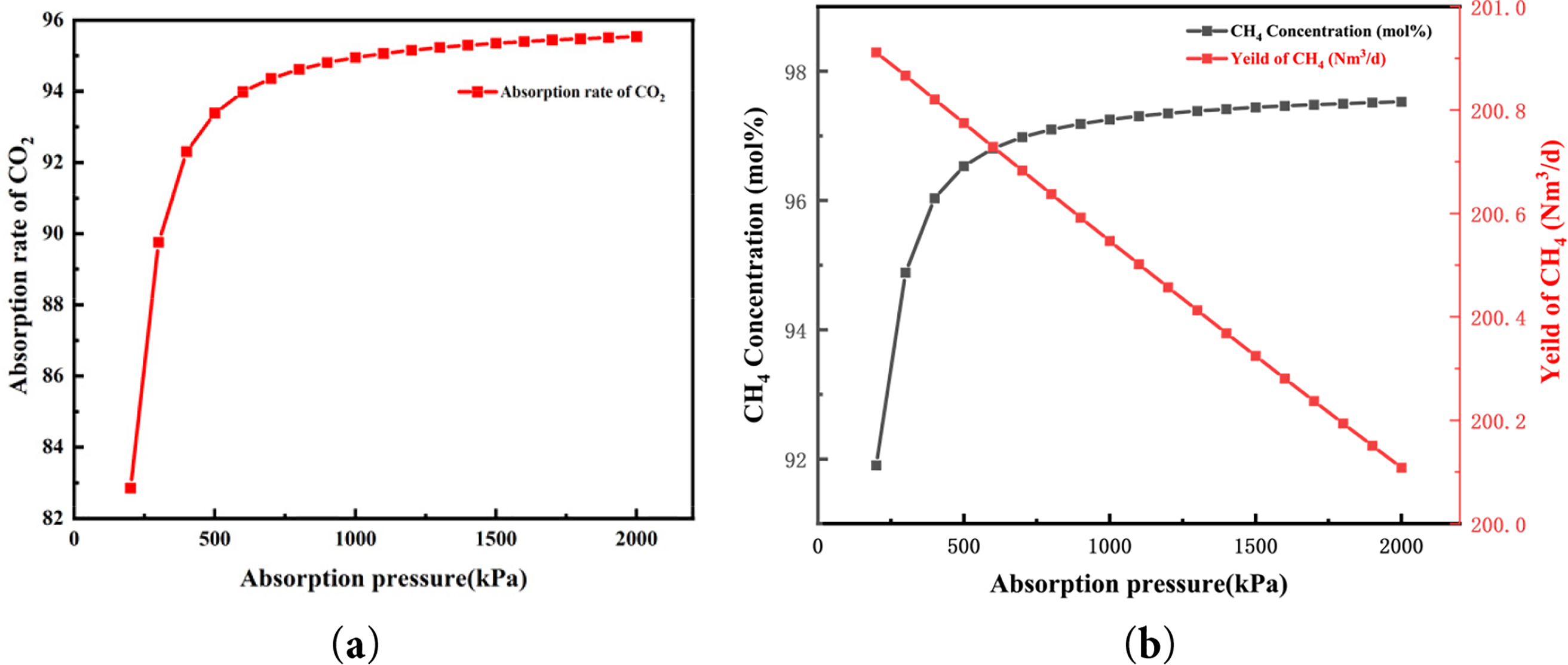
Figure 2: Influence of the pressure inside the absorber on (a) the CO2 absorption rate and (b) the concentration and yield of CH4
3.2 Concentration and Flow of Lean Solution
When the concentration and flow rate of the absorbent solution are constant, increasing the absorption pressure to a certain value stabilizes the CO2 absorption efficiency. Therefore, optimization of the monoethanolamine (MDEA) absorbent solution concentration and flow rate was carried out under an absorption pressure of 1200 kPa.
After Aspen simulation calculations, the effects of flow rate on CO2 absorption efficiency and CH4 concentration were analyzed for lean liquid concentrations of 15%, 20%, 25%, and 30% as shown in Fig. 3. As depicted in Fig. 3, the trends of how flow rate affects CO2 absorption efficiency and CH4 concentration are similar across different concentrations. When the flow rate of the lean liquid is constant, increasing the MDEA concentration from 15 to 20 mol% results in increased CO2 capture. However, further increases in the lean liquid concentration do not significantly raise CH4 concentration; instead, there is a declining trend. This is because the higher MDEA concentration inhibits the ionization of water molecules, affecting the reactions of CO2 and OH-, thereby reducing both CO2 absorption efficiency and CH4 concentration. Therefore, a lean liquid concentration of 20 mol% of MDEA is chosen for efficient CO2 absorption. Similar non-linear effects of amine concentration on CO2 solubility have been reported in recent thermodynamic studies [39].
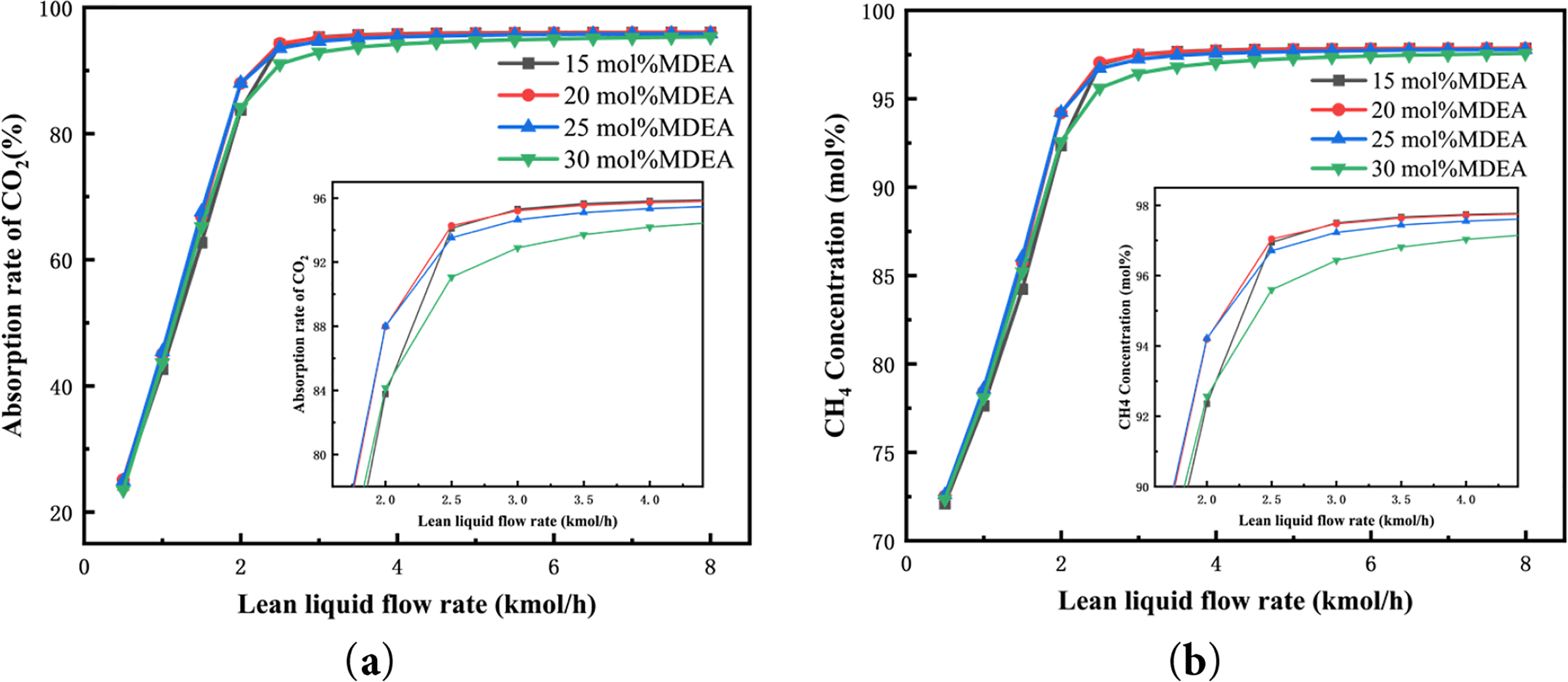
Figure 3: Influence of lean liquid concentration and flow rate on (a) the CO2 absorption rate and (b) the CH4 concentration in the product gas
When the lean liquid concentration is held constant, increasing the flow rate of the lean liquid results in an initial increase followed by stabilization of CO2 absorption efficiency and CH4 concentration. At lower flow rates of the lean liquid, the MDEA solution may not completely absorb CO2 from the mixed gas. Increasing the flow rate of the lean liquid enhances the MDEA content, effectively promoting early-stage absorption of CO2 by the lean liquid and rapidly increasing the CH4 concentration. However, once the lean liquid flow rate reaches a certain threshold, mass transfer limitations restrict further reaction progress, leading to a balanced CO2 absorption reaction. Continuously increasing the lean liquid flow rate does not significantly enhance CH4 concentration. On the contrary, a larger amount of lean liquid increases regeneration energy consumption and circulation load, thereby raising overall operational energy consumption and CH4 recovery energy. Under an absorption pressure of 1200 kPa, with a lean liquid of 20 mol% MDEA and a flow rate of 2.5 kmol/h, CO2 absorption efficiency reached 94.28%, and the CH4 concentration in the product gas was 97.04 mol%. These values meet natural gas pipeline transportation standards. Therefore, these parameters are selected as optimal for the concentration and flow rate of the lean liquid in the absorption process.
CO2 absorption is an exothermic reaction, and the temperature of the lean liquid entering the absorption tower affects the efficiency of CO2 absorption and the methane (CH4) concentration in the product gas. Therefore, this section focuses on optimizing and analyzing the temperature of the lean liquid. Based on the optimized process parameters mentioned above—absorption pressure of 1200 kPa and lean liquid concentration of 20 mol%—simulation analysis was conducted to assess the impact of different flow rates and temperatures of the lean liquid on CO2 absorption efficiency and CH4 concentration.
Fig. 4 illustrates the effect of the lean solvent inlet temperature on CO2 absorption efficiency and methane concentration. As the lean solvent temperature increases, both CO2 absorption efficiency and CH4 concentration exhibit a similar decreasing trend, which is consistent with the findings reported by Zhang et al. [40]. In addition, the most pronounced decline is observed when the lean solvent flow rate is 2 kmol/h. CO2 absorption by the lean liquid is an exothermic reaction, where lower temperatures favor the equilibrium shift towards CO2 absorption. As the lean liquid temperature rises, the occurrence of reverse reactions reduces CO2 absorption efficiency, leading to an increased CO2 content in the product gas discharged from the top of the absorption tower and a subsequent decrease in CH4 concentration. According to the graph, when the lean liquid flow rate is 2 kmol/h, increasing the lean liquid temperature from 303.15 to 323.15 K results in CO2 absorption efficiency and CH4 yield decreasing to 59.95 and 82.68 mol%, respectively. Once the lean liquid flow rate exceeds a certain value (greater than 2.5 kmol/h), increased absorption of CO2 by more MDEA reduces the saturation of the rich liquid. Therefore, effective CO2 absorption can still be maintained within the temperature range of 293.15 to 308.15 K. Although lower temperatures of the lean liquid can enhance CO2 absorption efficiency and CH4 concentration, cooling the lean liquid to low temperatures requires substantial cooling water and pump power consumption at the bottom of the regeneration tower. Additionally, in practical production, the viscosity of the solution increases with decreasing reaction temperature, leading to reduced diffusion coefficients and absorption rates. Based on the analysis above, at a lean liquid flow rate of 2.5 kmol/h, a lean liquid temperature of 298.15 K is chosen as optimal for entering the absorption tower.
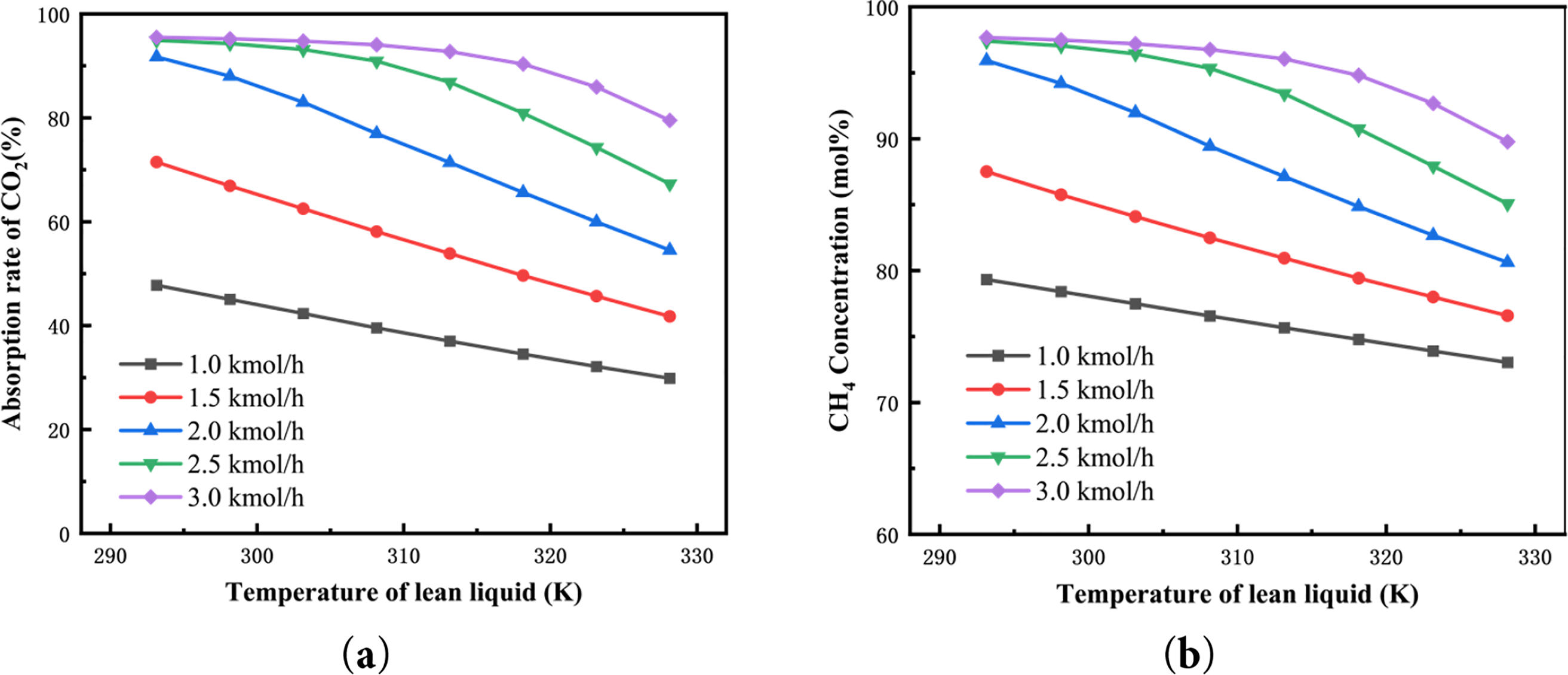
Figure 4: Influence of lean liquid temperature on (a) the CO2 absorption rate and (b) the CH4 concentration of product gas
3.4 Number of Absorption Trays
A tray column was selected for the absorption process, and the number of trays directly affects the mass transfer efficiency between the gas and liquid phases. Fig. 5 illustrates the relationship between the number of trays, CO2 absorption efficiency, and methane concentration in the product gas. Under constant operating conditions—namely a lean solvent concentration of 20 mol% MDEA, temperature of 298.15 K, flow rate of 2.5 kmol/h, and absorption pressure of 1200 kPa—increasing the number of trays enhances both CO2 absorption efficiency and CH4 concentration. This observation is consistent with common industrial practice. The vertical axis values correspond to separation parameters at each plate level. As the number of plates in the absorption tower increases (15, 20, 25), both CO2 absorption efficiency and CH4 concentration show an increasing trend. Specifically, CO2 absorption efficiencies are 88.60, 94.29, and 97.21 mol%, respectively, while CH4 concentrations are 94.46, 97.04, and 98.43 mol%, respectively. This is because increasing the number of plates enlarges the contact area between CO2 and the lean liquid, thereby facilitating more CO2 absorption by the lean liquid. However, the relationship between CO2 absorption and the number of plates is not linear. At 25 plates, CO2 absorption by the lean liquid approaches saturation, and both CO2 absorption efficiency and CH4 concentration stabilize without significant increases. In addition, an excessive number of trays increases both equipment manufacturing costs and operating expenses. From an economic perspective, the number of trays is directly related to the following aspects: (1) Equipment manufacturing cost: The more trays there are, the greater the column height and the higher the complexity of the internal structure; (2) Footprint and installation cost: Increasing the number of trays leads to larger column dimensions and higher infrastructure investment; (3) Operation and maintenance cost: A greater number of trays may result in increased pressure drop (although a per-tray pressure drop of 0.25 kPa is assumed in this study), thereby raising energy consumption. Therefore, selecting 20 trays represents a reasonable techno-economic compromise, as it achieves the required CH4 concentration in the product gas to meet the natural gas pipeline transmission standard (≥97 mol%) while avoiding excessive investment and operational burden.
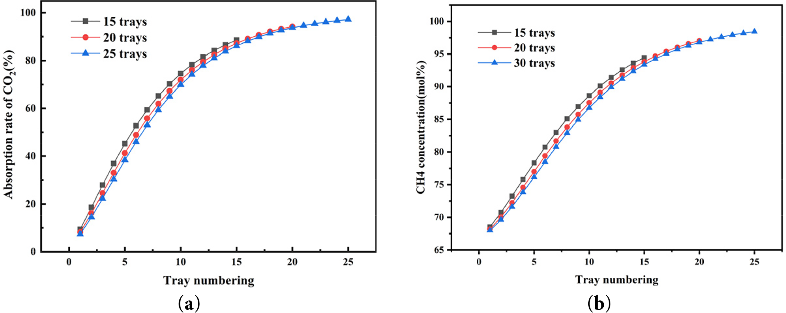
Figure 5: Influence of the number of trays on (a) the CO2 absorption rate and (b) the CH4 concentration of product gas
3.5 Reboiler Duty and Tray Numbers in Regeneration Tower
After the MDEA solution in the absorption tower absorbs CO2, it undergoes heating regeneration in the regeneration tower. The regenerated MDEA lean solution is pressurized, cooled, and then returned to the absorption tower for the next absorption cycle. The performance of the reboiler in the regeneration tower determines the regeneration capacity of the absorbent solution.
Fig. 6 depicts the effect of reboiler power on CO2 desorption rate in the rich solution and CH4 concentration in the product gas. As shown in the graph, increasing reboiler power initially enhances both CO2 desorption rate and CH4 concentration in the product gas, followed by stabilization. At a reboiler power of 3 kW, the CO2 desorption rate reaches 89.68%, indicating that most of the CO2 absorbed in the MDEA solution has been removed. Increasing the reboiler power to 4 kW raises the CO2 removal rate to 99.67%. However, since the residual CO2 in the MDEA solution is minimal at this point, further increasing reboiler power does not significantly improve CO2 removal rate. At this stage, the CH4 concentration in the product gas discharged from the top of the absorption tower stabilizes at 97.01 mol%, with a methane recovery rate of 99.78%. Based on the above analysis, a reboiler power of 4 kW is chosen as optimal. The choice of 10 trays in the regenerator can be justified from the following perspectives. First, unlike the absorber, the main objective of the regenerator is to fully desorb CO2 from the rich solvent. The performance of the regenerator is relatively less sensitive to the number of trays compared to the absorber, which requires highly efficient multi-stage gas-liquid mass transfer. Therefore, increasing the number of trays in the regenerator has a limited impact on overall performance. Second, as shown in Table 1 and Fig. 6, the current configuration requires only 4 kW of reboiler duty to achieve a CO2 removal rate of 99.67%, while maintaining a CH4 concentration of 97 mol% in the product gas, indicating that the system is already in an efficient regeneration state. The existing 10 trays are sufficient to meet the mass transfer and separation requirements. Reducing the number of trays further would result in a CH4 concentration in the product gas that does not meet the required standard of 97 mol%. For instance, as shown in Table 1, when the tray number is reduced to 5, the CH4 concentration in the product gas drops to 96.9 mol%, failing to meet the 97 mol% requirement. Finally, increasing the number of trays results in higher capital costs, larger equipment size, increased reboiler duty, and pressure drop. However, the simulation results indicate that with the current 10 tray configuration, the CO2 concentration in the MDEA rich solvent is already close to complete desorption, and adding more trays would have negligible benefits in improving the product gas purity.
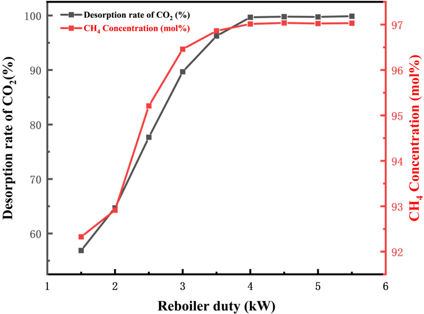
Figure 6: Effect of reboiler load on CO2 desorption rate and CH4 concentration of product gas
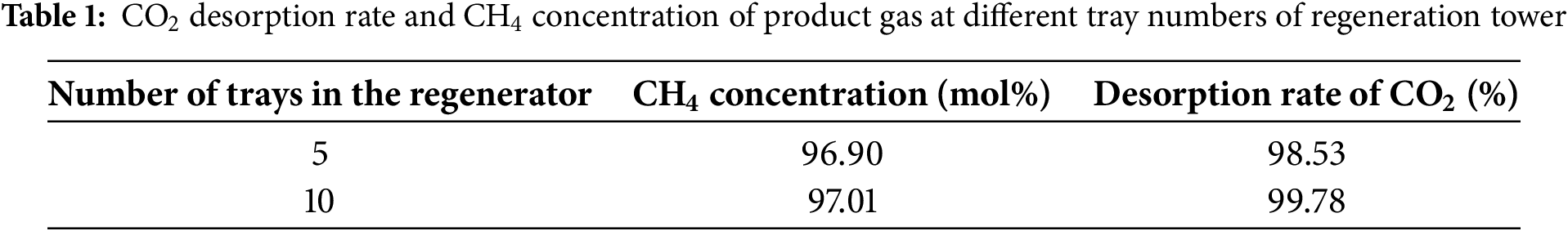
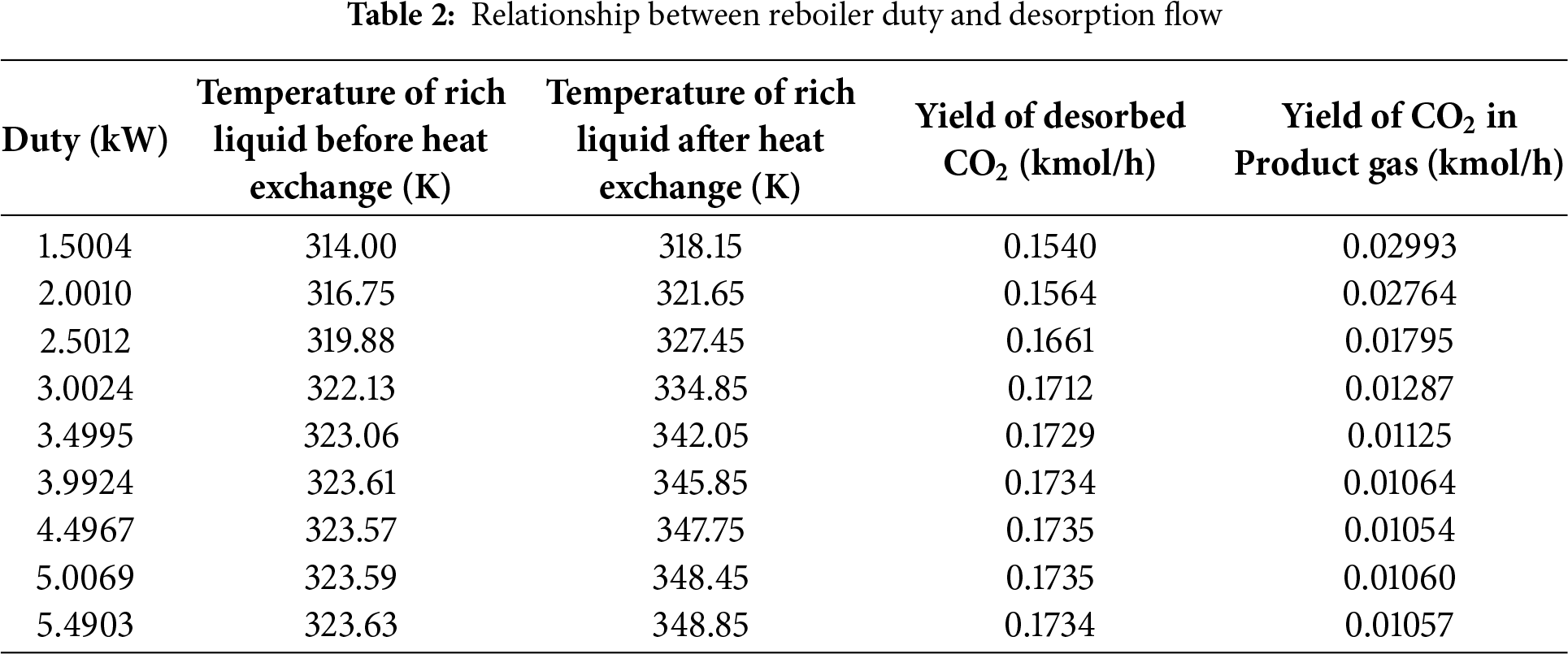
Table 2 presents the relationship between reboiler power and CO2 desorption gas flow rate. As reboiler power gradually increases, the amount of CO2 desorbed in the regeneration tower also increases, leading to a decrease in the CO2 content in the product gas discharged from the absorption tower. Increasing the reboiler load in the regeneration tower can raise the temperatures and CO2 removal efficiency of the MDEA-rich solution before and after the heat exchanger. Therefore, enhancing the temperature of the MDEA-rich solution entering the heat exchanger can improve CO2 removal efficiency under the same reboiler power. It should be noted that although the inlet and outlet temperatures of the lean–rich heat exchanger (E-1) vary under different reboiler duties (Table 2), the heat-exchanger configuration itself was kept constant, and the minimum temperature approach remained above 5 K. The temperature variations arise solely from process coupling rather than changes in heat-exchanger design. Therefore, optimization of heat-exchanger parameters is not included in this system-level study.
3.6 Energy Consumption Analysis
Based on the optimization of key absorption parameters in previous sections, the determined absorption process parameters are as follows: absorption pressure of 1200 kPa, MDEA lean liquid concentration of 20 mol%, lean liquid flow rate of 2.5 kmol/h, temperature of 298.15 K, 20 plates in the absorption tower, 10 plates in the regeneration tower, and a reboiler power of 4 kW. The initial pressure of the feed gas is 110 kPa, with a compression ratio of 10.91 before and after single-stage compression, hence employing two-stage compression with intercooling for pressurization before entering the absorption tower for reaction. Table 3 lists the optimized logistics information and Table 4 presents the parameters of the absorption process equipment units and energy consumption values, while Fig. 7 illustrates the energy consumption structure of this process. The overall energy consumption is 5.29 kW, with gas compression unit, pump transport unit, and reboiler energy consumption at 1.24, 0.667, and 3.99 kW, respectively. These correspond to 23.38%, 1.22%, and 75.40% of the total energy consumption, highlighting the reboiler and gas compression units as key energy-consuming components. The methane (CH4) content in the product gas is 5.98 kg/h, with CH4 recovery energy consumption at 0.8852 kWh/kg CH4. The minimum separation work in the separation process is 0.1297 kWh/kg CH4, resulting in an ECI (Energy Consumption Index) value of 6.82. Increasing the temperature of the high-pressure feed gas after compression allows this heat to be utilized for preheating the MDEA-rich solution, thereby reducing reboiler power and lowering the overall energy consumption of the absorption process.
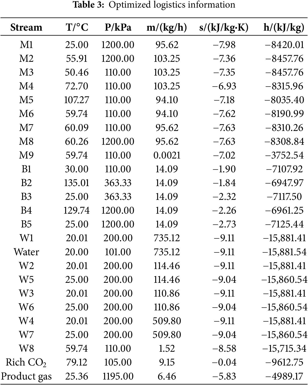
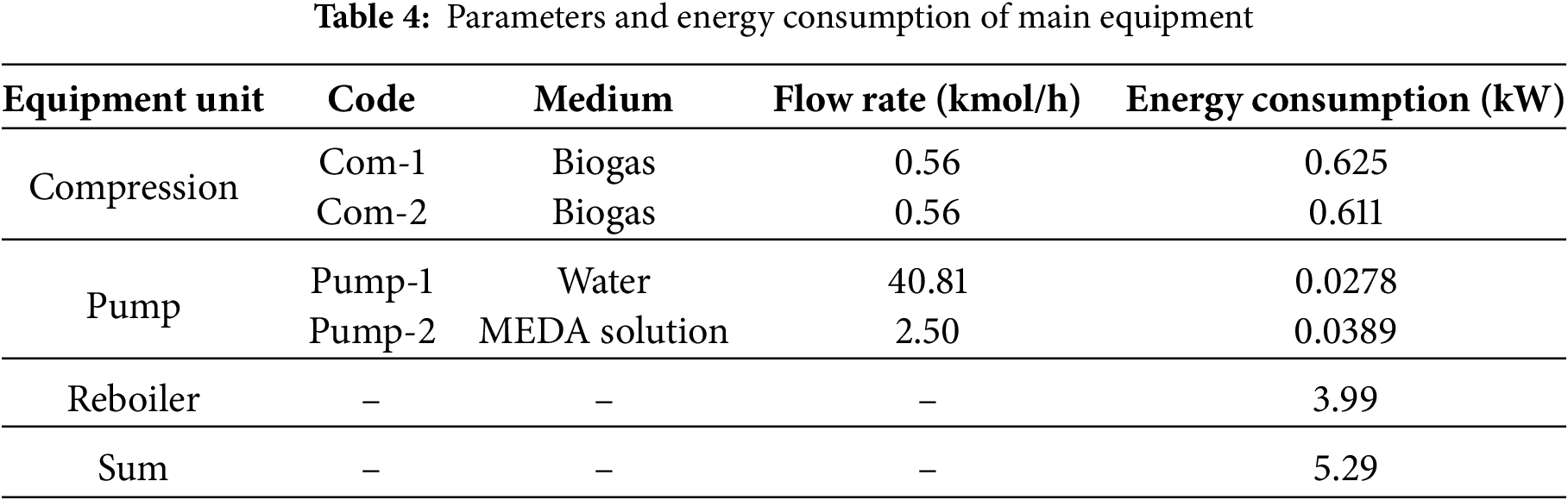
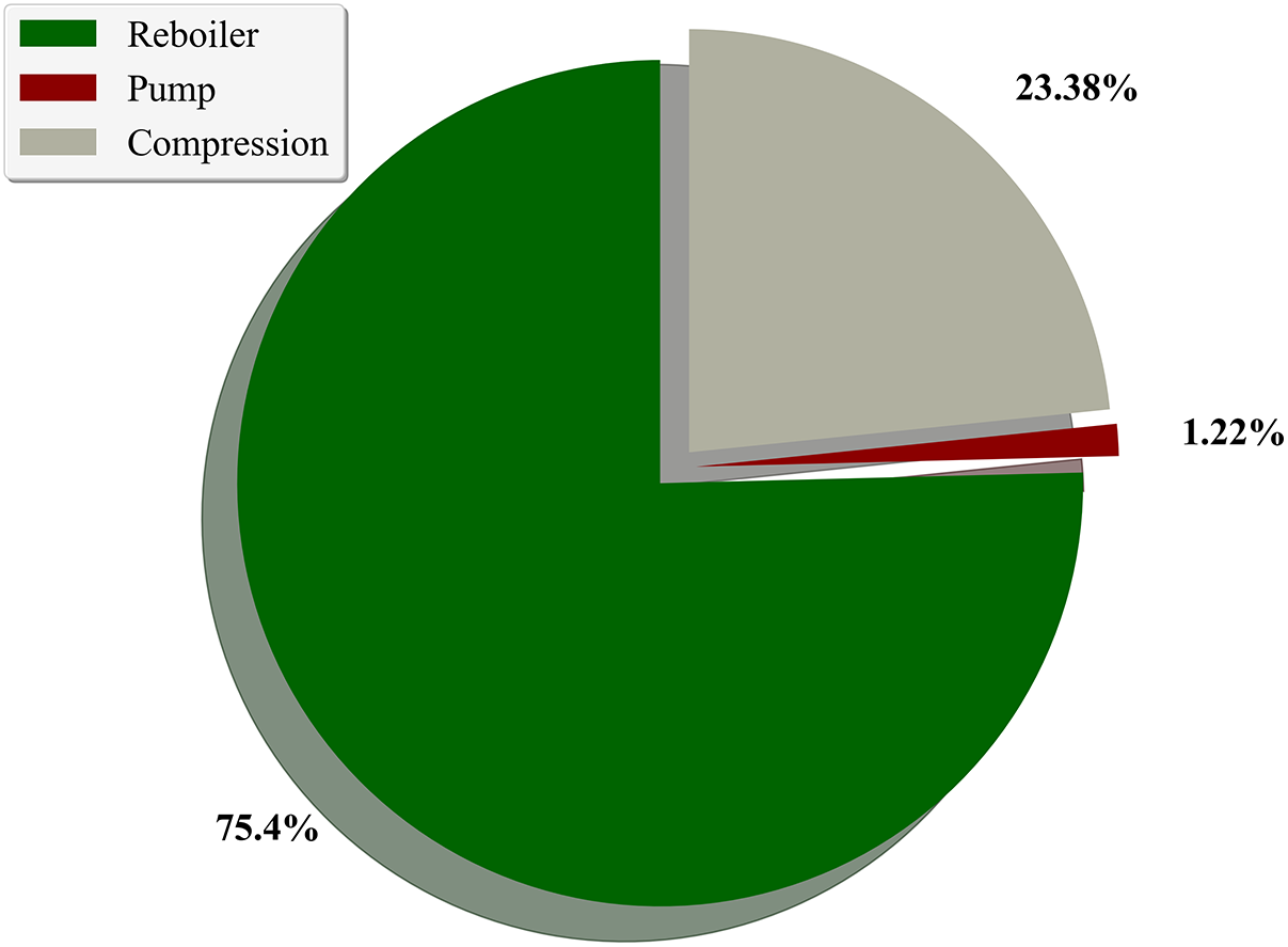
Figure 7: Energy consumption proportion of each unit
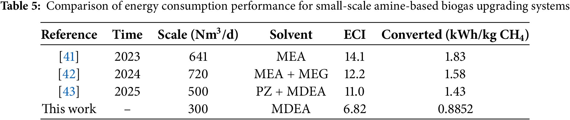
To further evaluate the energy consumption performance of this study, the optimized unit methane recovery energy consumption (0.8852 kWh/kg CH4) was compared with recently published small-scale amine-based biogas upgrading systems (Table 5). It can be observed that the energy consumption achieved in this study at a scale of 300 Nm3/d is lower than most reported MEA or mixed-amine systems, and the Energy Consumption Index (ECI = 6.82) is also at a relatively low level. This demonstrates that the MDEA solvent and parameter optimization strategy adopted in this work offer good energy consumption advantages for small- and medium-scale applications, particularly for urban distributed biogas projects sensitive to operational costs.
3.7 Energy Consumption Optimization Strategies
Simulation results indicate that the reboiler accounts for approximately 75.4% of the total energy consumption (see Fig. 7), making it the most energy-intensive unit in the absorption–regeneration process. In addition to the previously optimized operating parameters (e.g., number of trays, solvent flow rate, and temperature), further analysis was conducted on potential strategies such as waste heat recovery and alternative solvent formulations, as outlined below:
(1) Feasibility and Integration Pathways of Waste Heat Recovery: In the current process, the feed gas is compressed from 110 to 1200 kPa. After two-stage compression, its temperature increases significantly (see Section 3.6). This high-temperature gas can be utilized as a low-grade heat source to partially replace the reboiler duty. Previous studies have shown that using hot compression exhaust or product gas to preheat the rich MDEA solution can substantially reduce the reboiler power demand and thereby alleviate the overall energy burden. Application recommendation: A waste-heat exchanger module can be integrated into the simulation system, where the compression exhaust is used for secondary heat exchange with the rich solvent (e.g., by adding an auxiliary heat exchanger downstream of E-1). This would reduce the amount of external steam or electric heating required [19]. Although waste-heat recovery has strong energy-saving potential, its quantitative evaluation involves additional system modeling requirements and heat-integration design that fall outside the scope of the present study. The research will be reported in detail in future work
(2) Energy Advantages of Alternative Solvent Formulations: In the current simulation, MDEA is employed as a representative tertiary amine solvent. Although it offers high selectivity, it requires relatively high regeneration temperatures (110°C–120°C), resulting in a high reboiler load. To mitigate this issue, the following formulation strategies may be considered: Activated amine systems (aMDEA): Composite solvents formed by blending MDEA with primary amines (e.g., PZ, MEA) or polyamines (e.g., AEEA) can improve absorption rates and achieve comparable removal efficiencies with lower regeneration energy requirements [13]. Mixed-solvent systems (e.g., MDEA + TBEE): The addition of hydrophobic solvents or surfactants can reduce the specific heat capacity of the solvent and improve mass transfer characteristics, thereby significantly lowering reboiler duty while enhancing tray efficiency in the absorber [44].
Application recommendation: In follow-up simulations, part of the MDEA concentration could be replaced with aMDEA while keeping the total amine concentration constant, in order to evaluate the reduction in energy consumption. Alternatively, experimental data could be coupled with the simulation to generate regressed thermophysical parameters for mixed-solvent systems.
This study simulates a small-scale urban centralized biogas system (300 Nm3/d) to investigate the impact of various process parameters on methane (CH4) concentration in the product gas and energy consumption. The objective is to identify optimal process parameters for MDEA chemical absorption and provide a comprehensive analysis of energy consumption under these optimal conditions.
With an absorption pressure of 1200 kPa, a lean MDEA concentration of 20 mol%, a lean liquid flow rate of 2.5 kmol/h, a lean liquid temperature of 298.15 K, 20 trays in the absorption tower, 10 trays in the regeneration tower, and a reboiler duty of 4 kW, the methane concentration in the product gas reaches 97 mol%, meeting the natural gas pipeline transportation standards. The overall energy consumption of the process is 5.29 kW, with the energy consumption breakdown as follows: gas compression unit (23.38%), pump transport unit (1.22%), and reboiler (75.40%). The reboiler and gas compression units are identified as the primary energy-consuming components. The energy consumption per unit of methane recovered is 0.8852 kWh/kg CH4, with an Energy Consumption Index (ECI) of 6.82.
This study specifically addresses small-scale urban centralized biogas systems (300 Nm3/d), which are being progressively deployed in urban-rural transition zones in China. These systems face challenges such as limited land area, sensitivity to energy consumption, and high operational costs. Through system simulation and parameter optimization, we propose a decarbonization process using MDEA as the solvent, with controlled thermal load and a CH4 recovery efficiency exceeding 97%. This offers a reusable design baseline for small- and medium-scale methane utilization systems, such as those in urban sewage treatment plants and kitchen waste gasification plants.
However, the current study has several inherent limitations. The simulation framework does not incorporate practical operational factors such as solvent aging, foaming, or real-world process fluctuations. Furthermore, the assumptions of ideal tray efficiency and simplified pressure drop may result in an overly optimistic performance assessment, underscoring the need for experimental validation to calibrate the model. Beyond these simplifications, the analysis does not explore advanced system integration measures, including waste heat recovery or solvent formulation optimization. It is also recognized that the equilibrium-stage model represents a deliberate simplification suited for system-level screening. Future research should integrate rigorous kinetic models for the MDEA–CO2 reaction system to support detailed column internals design and dynamic process analysis.
Future research will focus on the following directions: integrating compression waste heat with a heat pump coupled system to reduce the reboiler load, exploring alternative solvent systems such as activated MDEA formulations, and developing a multi-objective optimization framework to balance gas purity, energy consumption, and cost. Additionally, efforts will be made to integrate simulations with experimental data, enhancing the engineering adaptability and practicality of the research findings.
Acknowledgement: Not applicable.
Funding Statement: This research was funded by Shenzhen Science and Technology Program, grant number No. ZDSYS20230626091400001; No. KCXST20221021111609024; No. KCXFZ20240903093459001.
Author Contributions: All authors contributed equally to this work. The authors confirm contribution to the paper as follows: Study conception and design: Luling Li, Peiming Li, Hengrong Zhang, Dongxu Ji, Jian Liu, Jianhui Liu, Guang Yang, Shuanshi Fan; methodology, Luling Li, Peiming Li, Hengrong Zhang, Dongxu Ji, Jian Liu, Jianhui Liu, Shuanshi Fan, Guang Yang; validation, Minghui Li, Zhengxiang Xu, Haofeng Lin, Xuemei Lang; data curation: Luling Li, Peiming Li, Minghui Li, Zhengxiang Xu, Haofeng Lin, Xuemei Lang; draft manuscript preparation: Luling Li, Peiming Li, Hengrong Zhang, Jian Liu, Jianhui Liu, Guang Yang; review and editing, Hengrong Zhang, Minghui Li, Zhengxiang Xu, Haofeng Lin, Xuemei Lang, Dongxu Ji; funding acquisition, Luling Li, Peiming Li, Dongxu Ji, Jian Liu, Jianhui Liu, Guang Yang. All authors reviewed the results and approved the final version of the manuscript.
Availability of Data and Materials: Data available on request from the authors.
Ethics Approval: Not applicable.
Conflicts of Interest: The authors declare no conflicts of interest to report regarding the present study.
References
1. Khan IU, Hafiz Dzarfan Othman M, Hashim H, Matsuura T, Ismail AF, Rezaei-DashtArzhandi M, et al. Biogas as a renewable energy fuel—a review of biogas upgrading, utilisation and storage. Energy Convers Manage. 2017;150:277–94. doi:10.1016/j.enconman.2017.08.035. [Google Scholar] [CrossRef]
2. Awe OW, Zhao Y, Nzihou A, Minh DP, Lyczko N. A review of biogas utilisation, purification and upgrading technologies. Waste Biomass Valorization. 2017;8(2):267–83. doi:10.1007/s12649-016-9826-4. [Google Scholar] [CrossRef]
3. Kopac T, Demirel Y. Optimizing CO2 capture from biogas: a comparative study of amine-based solvents through aspen plus simulations. Biomass Convers Biorefin. 2025;15(14):21327–47. doi:10.1007/s13399-025-06668-5. [Google Scholar] [CrossRef]
4. Wu T, Wang X, Li D, Yi Z. Emission of volatile organic sulfur compounds (VOSCs) during aerobic decomposition of food wastes. Atmos Environ. 2010;44(39):5065–71. doi:10.1016/j.atmosenv.2010.09.019. [Google Scholar] [CrossRef]
5. Lecharlier A, Carrier H, Le Hécho I. Characterization of biogas and biomethane trace compounds: a critical review of advances in in situ sampling and preconcentration techniques. Anal Chim Acta. 2022;1229:340174. doi:10.1016/j.aca.2022.340174. [Google Scholar] [PubMed] [CrossRef]
6. Poeschl M, Ward S, Owende P. Environmental impacts of biogas deployment-part II: life cycle assessment of multiple production and utilization pathways. J Clean Prod. 2012;24:184–201. doi:10.1016/j.jclepro.2011.10.030. [Google Scholar] [CrossRef]
7. Ryckebosch E, Drouillon M, Vervaeren H. Techniques for transformation of biogas to biomethane. Biomass Bioenergy. 2011;35(5):1633–45. doi:10.1016/j.biombioe.2011.02.033. [Google Scholar] [CrossRef]
8. Ali Abd A, Roslee Othman M, Helwani Z, Kim J. An overview of biogas upgrading via pressure swing adsorption: navigating through bibliometric insights towards a conceptual framework and future research pathways. Energy Convers Manage. 2024;306:118268. doi:10.1016/j.enconman.2024.118268. [Google Scholar] [CrossRef]
9. Sang Sefidi V, Luis P. Advanced amino acid-based technologies for CO2 capture: a review. Ind Eng Chem Res. 2019;58(44):20181–94. doi:10.1021/acs.iecr.9b01793. [Google Scholar] [CrossRef]
10. Bauer F, Persson T, Hulteberg C, Tamm D. Biogas upgrading-technology overview, comparison and perspectives for the future. Biofuels Bioprod Bioref. 2013;7(5):499–511. doi:10.1002/bbb.1423. [Google Scholar] [CrossRef]
11. Hosseini SE, Wahid MA. Development of biogas combustion in combined heat and power generation. Renew Sustain Energy Rev. 2014;40:868–75. doi:10.1016/j.rser.2014.07.204. [Google Scholar] [CrossRef]
12. Xue Q, Liu F, Li Z, Wang X, Sun X, Liu M, et al. Hydrate-based multistage biogas separation using a novel jet impingement stream reactor. Energy Fuels. 2023;37(15):11142–51. doi:10.1021/acs.energyfuels.3c01119. [Google Scholar] [CrossRef]
13. Privalova E, Rasi S, Mäki-Arvela P, Eränen K, Rintala J, Murzin DY, et al. CO2 capture from biogas: absorbent selection. RSC Adv. 2013;3(9):2979. doi:10.1039/c2ra23013e. [Google Scholar] [CrossRef]
14. Petersson A, Wellinger A. Biogas upgrading technologies—developments and innovations. Paris, France: IEA Bioenergy; 2009. [Google Scholar]
15. Cavaignac RS, Ferreira NL, Guardani R. Techno-economic and environmental process evaluation of biogas upgrading via amine scrubbing. Renew Energy. 2021;171:868–80. doi:10.1016/j.renene.2021.02.097. [Google Scholar] [CrossRef]
16. Vega F, Cano M, Portillo E, Camino S, Camino JA, Navarrete B. Kinetic characterization of solvents for CO2 capture under partial oxy-combustion conditions. Energy Proc. 2017;114:2055–60. doi:10.1016/j.egypro.2017.03.1340. [Google Scholar] [CrossRef]
17. Kadam R, Panwar NL. Recent advancement in biogas enrichment and its applications. Renew Sustain Energy Rev. 2017;73:892–903. doi:10.1016/j.rser.2017.01.167. [Google Scholar] [CrossRef]
18. Kismurtono M. Upgrade biogas purification in packed column with chemical absorption of CO2 for energy alternative of small industry (UKM-Tahu). Int J Eng Technol. 2011;11(1):83–6. [Google Scholar]
19. Vega F, Cano M, Gallego LM, Camino S, Camino JA, Navarrete B. Evaluation of MEA 5 M performance at different CO2 concentrations of flue gas tested at a CO2 capture lab-scale plant. Energy Proc. 2017;114:6222–8. doi:10.1016/j.egypro.2017.03.1760. [Google Scholar] [CrossRef]
20. Yu CH, Huang CH, Tan CS. A review of CO2 capture by absorption and adsorption. Aerosol Air Qual Res. 2012;12(5):745–69. doi:10.4209/aaqr.2012.05.0132. [Google Scholar] [CrossRef]
21. Persson M. Evaluation of upgrading techniques for biogas. Stockholm, Sweden: Swedish Gas Center; 2003. [Google Scholar]
22. Lu JG, Zheng YF, He DL. Selective absorption of H2S from gas mixtures into aqueous solutions of blended amines of methyldiethanolamine and 2-tertiarybutylamino-2-ethoxyethanol in a packed column. Sep Purif Technol. 2006;52(2):209–17. doi:10.1016/j.seppur.2006.04.003. [Google Scholar] [CrossRef]
23. Esfandyari M, Moghaddam AH. Comparative analysis of amine-based solvents for energy efficient post-combustion CO2 capture. Fuel. 2025;402:135982. doi:10.1016/j.fuel.2025.135982. [Google Scholar] [CrossRef]
24. Borhani TN, Wang M. Role of solvents in CO2 capture processes: the review of selection and design methods. Renew Sustain Energy Rev. 2019;114:109299. doi:10.1016/j.rser.2019.109299. [Google Scholar] [CrossRef]
25. Loachamin D, Casierra J, Calva V, Palma-Cando A, Ávila EE, Ricaurte M. Amine-based solvents and additives to improve the CO2 capture processes: a review. ChemEngineering. 2024;8(6):129. doi:10.3390/chemengineering8060129. [Google Scholar] [CrossRef]
26. Zhu Y, Wang S, Zhao B, Chen C. Simulation of amine-based carbon capture system and selection of absorbents. J Tsinghua Univ Sci Technol Nat Sci Ed. 2009;11:1822–5. doi:10.3321/j.issn:1000-0054.2009.11.021. [Google Scholar] [CrossRef]
27. de Ávila SG, Logli MA, Silva LCC, Fantini MCA, Matos JR. Incorporation of monoethanolamine (MEAdiethanolamine (DEA) and methyldiethanolamine (MDEA) in mesoporous silica: an alternative to CO2 capture. J Environ Chem Eng. 2016;4(4):4514–24. doi:10.1016/j.jece.2016.10.015. [Google Scholar] [CrossRef]
28. Deng F, Tian G, Zeng F. Study on the factors influencing natural gas decarbonization based on HYSYS simulation. Chem Eng Technol Dev. 2015;44(2):40–3. [Google Scholar]
29. Antonini C, Pérez-Calvo JF, Van der Spek M, Mazzotti M. Optimal design of an MDEA CO2 capture plant for low-carbon hydrogen production—a rigorous process optimization approach. Sep Purif Technol. 2021;279:119715. doi:10.1016/j.seppur.2021.119715. [Google Scholar] [CrossRef]
30. Francisco López A, Lago Rodríguez T, Faraji Abdolmaleki S, Galera Martínez M, Bello Bugallo PM. From biogas to biomethane: an in-depth review of upgrading technologies that enhance sustainability and reduce greenhouse gas emissions. Appl Sci. 2024;14(6):2342. doi:10.3390/app14062342. [Google Scholar] [CrossRef]
31. Fajrina N, Yusof N, Ismail AF, Aziz F, Bilad MR, Alkahtani M. A crucial review on the challenges and recent gas membrane development for biogas upgrading. J Environ Chem Eng. 2023;11(3):110235. doi:10.1016/j.jece.2023.110235. [Google Scholar] [CrossRef]
32. Moghaddam AH, Esfandyari M, Sakhaeinia H. Optimization of amine-based carbon capture: simulation and energy efficiency analysis of absorption section. Results Eng. 2024;24:103574. doi:10.1016/j.rineng.2024.103574. [Google Scholar] [CrossRef]
33. Perry RH, Green DW, Maloney JO. Perry’s chemical engineers’ handbook. 9th ed. New York, NY, USA: McGraw Hill; 2019. [Google Scholar]
34. Interlenghi SF, de Medeiros JL, de Queiroz F, Araújo O. On small-scale liquefaction of natural gas with supersonic separator: energy and second law analyses. Energy Convers Manage. 2020;221:113117. doi:10.1016/j.enconman.2020.113117. [Google Scholar] [CrossRef]
35. Mehrpooya M, Khodayari R, Ali Moosavian SM, Dadak A. Optimal design of molten carbonate fuel cell combined cycle power plant and thermophotovoltaic system. Energy Convers Manage. 2020;221:113177. doi:10.1016/j.enconman.2020.113177. [Google Scholar] [CrossRef]
36. Song S, Xun T, Bu X. Impact of reduced oxygen purity in air separation systems on IGCC operation. Therm Power Gener. 2018;47(6):127–31. [Google Scholar]
37. Kotas TJ. The exergy method of thermal plant analysis. Oxford, UK: Butterworth-Heinemann; 1985. [Google Scholar]
38. Sandler SI. Chemical, biochemical, and engineering thermodynamics. 5th ed. Hoboken, NJ, USA: John Wiley & Sons, Inc; 2017. [Google Scholar]
39. Guo L, Wang Y, Wang B, Wang N, Zhang L, Chen Y. A simplified semi-empirical model for modeling of CO2 solubilities in aqueous MDEA and MEA solutions. Fluid Phase Equilib. 2022;555:113352. doi:10.1016/j.fluid.2021.113352. [Google Scholar] [CrossRef]
40. Zhang G, Liu J, Qian J, Zhang X, Liu Z. Review of research progress and stability studies of amine-based biphasic absorbents for CO2 capture. J Ind Eng Chem. 2024;134:28–50. doi:10.1016/j.jiec.2024.01.013. [Google Scholar] [CrossRef]
41. Jørsboe JK, Vinjarapu SHB, Neerup R, Møller AC, Jensen S, Abildskov J, et al. Mobile pilot plant for CO2 capture in biogas upgrading using 30 wt% MEA. Fuel. 2023;350:128702. doi:10.1016/j.fuel.2023.128702. [Google Scholar] [CrossRef]
42. Kristian Jørsboe J, Neerup R, Hema Bhavya Vinjarapu S, Møller AC, Jensen S, Abildskov J, et al. Demonstration of water-lean 30 wt% MEA + 15 wt% MEG with rich solvent recycle for biogas upgrading. Fuel. 2024;363:130936. doi:10.1016/j.fuel.2024.130936. [Google Scholar] [CrossRef]
43. Jørsboe JK, Jensen EH, Jensen S, Wiers P, Karlsson J, Løge IA, et al. Biogas upgrading with PZ/MDEA: pilot demonstration of absorber intercooling, cold solvent split and lean vapor compression. Fuel. 2025;396:135296. doi:10.1016/j.fuel.2025.135296. [Google Scholar] [CrossRef]
44. Mota-Martinez MT, Hallett JP, Mac Dowell N. Solvent selection and design for CO2 capture-how we might have been missing the point. Sustainable Energy Fuels. 2017;1(10):2078–90. doi:10.1039/c7se00404d. [Google Scholar] [CrossRef]
Cite This Article
 Copyright © 2026 The Author(s). Published by Tech Science Press.
This work is licensed under a Creative Commons Attribution 4.0 International License , which permits unrestricted use, distribution, and reproduction in any medium, provided the original work is properly cited.
 Downloads
 Citation Tools