
 Submit a Paper
 Propose a Special lssue
 Open Access
ARTICLE
Experimental Investigation on Heating Performance and Frosting Behavior of an Integrated R290 Secondary Loop Heat Pump
1 China Three Gorges Renewables (Group) Co., Ltd. (CTGR), Beijing, China
2 School of Energy and Power Engineering, University of Shanghai for Science and Technology, Shanghai, China
3 School of Computing, Engineering & Digital Technologies, Teesside University, Middlesbrough, UK
4 Department of Chemical and Biochemical Engineering, Dongguk University, 30, Pildong-ro 1-gil, Seoul, Republic of Korea
* Corresponding Authors: Kang Li. Email: ; Soheil Mohtaram. Email:
Frontiers in Heat and Mass Transfer 2026, 24(2), 4 https://doi.org/10.32604/fhmt.2026.077274
Received 05 December 2025; Accepted 19 January 2026; Issue published 30 April 2026
 View Full Text
 Download PDF
Abstract
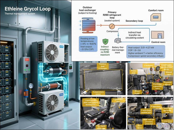
Energy storage batteries require strict thermal management due to temperature sensitivity, operating optimally within a narrow thermal range. Simultaneously, control rooms demand stable and comfortable ambient conditions for staff staying long-term. Conventional temperature control systems typically employ isolated solutions, resulting in functional fragmentation and inefficient resource utilization. To address these challenges, this study proposes and implements an integrated R290 secondary loop heat pump air-conditioning system designed to simultaneously manage the thermal environments of both energy storage batteries and control rooms. By adopting a secondary-loop coupling architecture, all thermal regulation is achieved indirectly via indirect heat transfer with a circulating ethylene glycol-based coolant, eliminating the risk of direct refrigerant (R290) exposure in occupied spaces and enhancing safety. The system supports multiple operational modes, enabling flexible and efficient dual-zone climate control. The heating performance—evaluated in terms of heat exchange capacity and coefficient of performance (COP)—is analyzed under varying ambient temperatures and compressor speeds. Additionally, the frosting behavior of the outdoor heat exchanger and its impact on heat transfer and system performance are examined. Results showed heat output ranged from 3.01 to 4.27 kW, and COP varied between 1.9 and 2.8. Ambient temperature (more dominant than compressor speed) and speed both affected performance: higher speed/warmer temperatures improved heat transfer efficiency; low temperatures accelerated frosting (e.g., −5°C reduced heat output by 19.67% and COP by 31.13%, vs. 13.72% and 12.40% at 5°C). These findings provide critical insights for optimizing heat transfer design and operation of integrated thermal management systems in energy storage facilities.Graphic Abstract
Keywords
Energy storage systems play a critical role in ensuring efficient energy retention, grid flexibility, and renewable integration. Among the available technologies, electrochemical batteries have emerged as the primary option owning to their high energy density, modularity, and extended cycle life [1,2]. Despite these advantages, energy storage batteries exhibit a pronounced sensitivity to temperature, operating optimally within a narrow thermal window. Deviations from the optimal thermal range can cause significant consequences: elevated temperatures may induce thermal runaway and accelerate material degradation, while lower temperatures substantially impair charge-discharge efficiency and reduce overall capacity [3–5].
At the system level, control rooms function as the operational hub for system operation and maintenance, requiring strict environmental standards to ensure thermal comfort and stable humidity for personnel working in prolonged shifts [6,7]. Conventional temperature regulation strategies typically employ independent air-conditioning systems for battery compartment and control rooms. However, this fragmented strategy often falls short in delivering coordinated thermal management. It compromises both battery safety and human comfort while contributing to resource inefficiencies caused by equipment redundancy and cumulative energy consumption. These limitations underscore the practical need to develop an integrated temperature control solution that simultaneously manages both battery and control room environments.
In designing such an integrated system—particularly through the use of—refrigerant selection is a critical factor influencing both system efficiency and environmental sustainability [8]. Following the Kigali Amendment to the Montreal Protocol, the high–global warming potential (GWP) refrigerants such as refrigerant R134a is facing stringent restrictions in engineering applications [9,10]. In this context, R290 (propane), a natural refrigerant, offers notable environmental advantages over R134a. It features zero ozone depletion potential (ODP = 0) and a remarkably low global warming potential (GWP = 3), making it a compelling alternative for eco-conscious system design [11,12]. In addition, R290 also possesses prominent characteristics such as a small molecular mass and elevated latent heat of vaporization [13,14].
Nonetheless, the adoption of R290 introduces safety considerations due to its flammability and explosiveness, leading to the widespread use of secondary loop systems as a preferred technical safeguard [15–17]. Khader et al. [18] compared R290 with R1234yf heat pump systems and demonstrated that R290 exhibits superior continuous heating performance. Furthermore, Luo et al. [19] investigated an integrated R290 thermal management system, reporting a COP of 1.22 at −20°C. Even at −30°C, the system maintained heat absorption capacity from the air, albeit with a minimum COP of 0.74.
Despite these advantages, operation under cold weather conditions introduces additional performance challenges. Low ambient temperatures combined with high humidity can result in frost accumulation on the outdoor heat exchanger surfaces [20,21]. This frost buildup significantly increases the thermal resistance on the air side, diminishing heat transfer efficiency and undermining the system’s ability to maintain consistent indoor thermal comfort [22–24].
Previous studies have extensively investigated frosting mechanisms and mitigation strategies in air-source heat pump systems. A systematic experimental investigation was carried out by Liu et al. [25] to characterize the frosting phenomena of microchannel heat exchangers and elucidate their fundamental effects on heat transfer performance within R134a heat pump systems for electric vehicles. By varying flow path configurations, pipeline layouts, and incoming airflow conditions, they aimed to mitigate frosting and enhance overall system performance through optimized design strategies. Similarly, Li et al. [26] examined CO2-based heat pump systems specifically designed for electric vehicles and observed that the frosting coverage area of the outdoor heat exchanger is inversely related to ambient temperature and directly related to compressor speed. Their findings highlighted that when frosting exceeds 40% coverage, there is a pronounced decline in both compressor suction pressure and the outlet pressure of the outdoor heat exchanger.
In another approach, He et al. [27] demonstrated that applying superhydrophobic surface treatments to heat exchangers can significantly prolong effective heat transfer performance under frosty conditions. Xue et al. [28], focusing on fin-tube heat exchangers, reported that both frost layer thickness and air pressure drop diminish as air temperature and relative humidity decrease, whereas the total frost mass exhibits an increasing trend. They also found that the influence of incoming airflow velocity on frost thickness is relatively minor; however, under lower airflow speeds, the cooling capacity of the heat exchanger deteriorates more rapidly. In a related study, Westhaeuser et al. [29] analyzed the frosting and defrosting behavior of vehicle heat pump systems, concluding that the system’s heat release per operational stage declines with reduced fan speed and as the number of frosting stages increases.
Despite these advances, the influence of frosting on integrated secondary-loop R290 systems designed for simultaneous battery and control-room management has not been adequately studied. This is primarily because a critical distinction exists in both the heat transfer medium and the phase-change process: unlike conventional systems where the refrigerant directly contacts the air and undergoes phase change within the heat exchanger, secondary-loop systems utilize a circulating coolant (such as a glycol solution) in the outdoor heat exchanger, which does not undergo phase change during heat transfer. Consequently, the empirical findings from standard heat pump systems cannot be directly extrapolated.
To address this challenge, this study designs and experimentally investigates an integrated R290-based secondary loop heat pump air-conditioning system tailored for energy storage batteries and control rooms. The research focuses on investigating the dynamic behavior of key performance indicators, including heat exchange capacity and coefficient of performance (COP), during heating operation. It also examines the evolution of frost formation on outdoor heat exchangers under varying environmental conditions, as well as the effect of frosting on the operational performance of the system. The objective is to generate foundational data and theoretical insights to support the development of frost prediction models, optimize defrosting strategies, and guide the practical engineering deployment of R290 heat pump air-conditioning systems.
To address the distinct thermal requirements of energy storage batteries and control rooms, an integrated secondary-loop heat pump air-conditioning system was developed using R290 as the natural refrigerant. The system features a compact and efficient refrigerant circuit architecture composed of a variable-frequency compressor, electronic expansion valve, liquid-liquid heat exchanger, and gas-liquid heat exchanger arranged in a closed-loop layout.
A high-efficiency gas-liquid separator is installed at the compressor inlet to prevent liquid slugging, while a sight glass is incorporated to facilitate real-time observation of refrigerant flow conditions. Guided by a secondary-loop coupling design approach, the system transfers heat between the primary R290 refrigerant circuit and the secondary coolant loop via two plate-type heat exchangers. All thermal management functions are carried out indirectly through a secondary loop circulating an ethylene glycol-based coolant, which inherently mitigates safety risks associated with direct refrigerant leakage into occupied control room spaces.
The system features multi-functional operational modes, including battery heat dissipation, room cooling, combined system cooling (room and battery), room heating, combined system heating, and waste heat recovery. Fig. 1 depicts a schematic of the R290 system’s different operational modes.

Figure 1: Schematic of operational modes for the R290 system when both the control room and energy storage battery simultaneously require cooling, the system automatically transitions into system cooling mode, as illustrated in (a). In practical applications, if only the control room is occupied, closing valve 10 isolates the battery circuit, switching operation to room cooling mode without structural changes to the refrigerant loop. During cold winter conditions, the system enters system heating mode, as shown in (b). In this mode, the compressor starts and operates continuously, and the system relies on two independent loops to achieve heat exchange and energy regulation: on one hand, a water pump drives the refrigerant carrier from the liquid-liquid heat exchanger to flow to the outdoor radiator, dissipating the unused cooling capacity directly to the outside environment; on the other hand, another water pump drives the refrigerant carrier to flow through the battery cooler and condenser. After completing the heat transfer process, the refrigerant carrier finally flows back to the gas-liquid heat exchanger, forming a complete heat cycle. Through precise regulation of valve positions within the heating circuit, the system can also provide targeted heating for either the battery or the control room independently, as operational needs dictate. In cases where the battery is operating within its optimal temperature range but the room demands minimal heating, the system switches to waste heat recovery mode (c). In this mode, battery waste heat warms the control room to reduce reliance on the heat pump, which activates for auxiliary heating only if the recovered heat is insufficient. Compared with conventional heat pump-only heating, this mode significantly improves overall energy efficiency. When the surrounding temperature falls into the occupant comfort zone, active thermal management is unnecessary for the control room, and battery thermal management becomes the primary concern. At low heat output, the system operates in battery heat dissipation mode (d). However, if the thermal load exceeds passive dissipation limits, the compressor engages. This mode is similar to system cooling (a), except that valve 5 is closed to enhance efficiency.
2.2 Experimental Scheme Design
Fig. 2 illustrates the schematic layout of the system as installed within the enthalpy difference laboratory. All experimental components are positioned outside the environmental chamber, and the system operates under a full fresh air circulation mode. To monitor system performance, four pressure measurement points (P) are strategically placed at the inlet and outlet of both the compressor and the expansion valve. Each pressure point is paired with a corresponding thermocouple for simultaneous pressure and temperature monitoring.

Figure 2: Layout of experimental setup for heat pump air-conditioning system to meet the cooling and heating requirements under different design conditions, appropriate heat exchangers were selected. Electronic expansion valves, which belong to flow-type capacity regulation systems, were used to control refrigerant flow. The compressor had undergone comprehensive performance and durability testing prior to the experiments.
Thermocouples are also mounted at the inlet and outlet of each heat exchanger in the coolant loop, providing continuous tracking of fluid temperature variations resulting from heat exchange processes. Due to limitations in the available experimental instrumentation, the refrigerant loop is not equipped with a direct flow meter. Six flow measurement points (marked as M) are distributed throughout the system, including the plate heat exchangers, evaporator, condenser, and battery cooler, enabling accurate assessment of flow conditions across critical components.
Given the flammability of R290, strict safety measures were adopted to mitigate leakage risks. Combustible gas detectors were installed along the refrigerant circuit. Upon detection of a leak, the compressor is immediately shut down by the system, and the ventilation system is activated to enhance air exchange rates, rapidly diluting the refrigerant concentration in the room. This prevents the R290 level from reaching its lower explosive limit and ensures safe operation. The specifications of the equipment are listed in Table 1.

The system components are arranged in a compact configuration to enhance integration and efficiency. The refrigerant circuit is designed with minimal length to reduce refrigerant charge, and all connections are welded to ensure reliable sealing and prevent leaks. Combustible gas detectors are installed near critical components such as the compressor and electronic expansion valve to enable real-time monitoring of potential R290 leakage. In the coolant circuit, flow resistance is minimized through shortened piping and a reduced number of bends. Furthermore, all equipment is thermally insulated to minimize heat exchange with the surrounding environment, thereby maintaining stable operating conditions and improving the accuracy of temperature measurements. The complete experimental setup is illustrated in Fig. 3.

Figure 3: Experimental system and components.
This experiment was conducted under 100% fresh air conditions, and thus the indoor temperature was equal to the outdoor ambient temperature. The heating experiments were conducted under the following conditions: the outdoor air volume is regulated at 3000 m3/h, while the opening degree of the electronic expansion valve is fixed at 30%. The indoor air intake volume is set to 300 m3/h, and the coolant flow rate is maintained at 8 L/min. Specifically, the experimental variables were divided into two categories based on their nature: variable environmental parameters, including the outdoor ambient temperature, and variable equipment operation parameters, including the compressor speed. The outdoor ambient temperatures are set at −5°C, 0°C, and 5°C, with −5°C representing the minimum operating temperature and the others serving as comparative conditions. Compressor speeds are tested at 4000, 5000, and 6000 r/min. To investigate frosting behavior, which is more prevalent under low-temperature and high-humidity conditions, additional experiments are conducted with relative humidity controlled between 85% and 95%. The specific parameters of the experimental test conditions have been compiled in Table 2.

2.3 Data Processing Methods and Uncertainty Evaluation
During the experiment, the refrigerant circuit lacked a flow measurement device due to equipment limitations. As a result, the heat exchange capacity was determined indirectly using data from the coolant circuit. Under the assumption of constant pressure and negligible heat loss, the coolant’s temperature change was attributed entirely to heat exchange. By measuring the mass flow rate and temperature difference of the coolant, the heat transfer across system components was calculated. Since this study focuses on heating performance, the heat exchange capacity of the gas-liquid heat exchanger is taken as the heating capacity. Combined with the system’s electrical energy consumption, COP was then derived. To ensure the reliability of the experimental data, each operating condition was repeated three times, and the final results are presented as the average of the three measurements. The formula for calculating heat exchange capacity is shown in Eq. (1).
In Eq. (1),
However, this indirect method introduces inherent deviations in the calculated heat exchange capacity, potentially affecting the accuracy of performance evaluation. Additionally, measurement uncertainties from sensors can influence results. The measurement errors associated with physical quantities that are directly measured can be derived by means of Eq. (3).
In the formula,
here,
The uncertainty values of all measured parameters are summarized in Table 3.

3.1 Heating Performance under Varying Operating Conditions
Frost formation can significantly influence the heating efficiency of heat pump systems. Therefore, the analysis first examines the heating performance of the integrated R290 secondary-loop system under different ambient temperatures and compressor speeds. As shown in Fig. 4, the compressor suction and discharge pressures and temperatures are plotted under three outdoor ambient temperatures (5°C, 0°C, and −5°C) and three compressor speeds (4000, 5000, and 6000 r/min), providing clear insight into the system’s thermodynamic behavior.

Figure 4: Variation of compressor suction and discharge pressures and temperatures under different operating conditions.
With the compressor speed increasing continuously, the suction pressure decreases substantially in the heat pump system. For example, at 5°C ambient temperature, suction pressure drops from 0.126 MPa at 4000 r/min to 0.077 MPa at 6000 r/min. In contrast, discharge pressure rises from 0.977 to 1.155 MPa under the same conditions. With the compressor speed fixed, higher ambient temperatures lead to higher suction and discharge pressures, reflecting improved refrigerant saturation conditions.
Similarly, suction temperature declines with increasing compressor speed due to enhanced superheat and reduced suction density, while discharge temperature increases sharply owing to higher compression work. At constant speed, both suction and discharge temperatures rise with increasing ambient temperature. The trends in temperature closely follow those of pressure, indicating strong coupling between thermal and hydraulic performance. Notably, as highlighted in Fig. 4, the magnitude of discharge temperature variation is considerably larger than that of suction temperature across all test conditions, underscoring the sensitivity of high-side performance to operating parameters.
Fig. 5 illustrates the variation in heat exchange capacity of the gas-liquid heat exchanger under different compressor speeds (4000, 5000, and 6000 r/min) and ambient temperatures (5°C, 0°C, and −5°C). The results reveal that increasing compressor speed consistently enhances heating capacity. For example, at 5°C ambient temperature, the capacity increases from 3426 W at 4000 r/min to 4266 W at 6000 r/min. At constant compressor speed, higher ambient temperatures result in greater heat exchange capacity, as higher source temperatures improve refrigerant evaporation and system energy transfer. At 5000 r/min, for instance, the capacity at 5°C is significantly higher than at −5°C.

Figure 5: Influence of compressor speed and ambient temperature on heat exchange capacity of gas-liquid heat exchanger.
Notably, at the same compressor speed, the heat exchange capacities at 0°C and −5°C are relatively close, suggesting a reduced performance sensitivity in the lower temperature range. This indicates that while both compressor speed and ambient temperature significantly influence system performance, the effect of ambient temperature diminishes at sub-zero conditions. Thus, within low-temperature operating ranges, increasing the compressor speed becomes a more effective means of enhancing heating capacity than relying on ambient thermal conditions.
Fig. 6 shows the relationship between coefficient of performance (COP) with compressor speed and ambient temperature. Under all tested ambient conditions, the COP increases with rising compressor speed. This trend arises because the gain in heating capacity exceeds the rise in power consumption, leading to improved system efficiency. For instance, as the compressor speed increases from 4000 to 6000 r/min, the COP rises across all ambient temperatures (5°C, 0°C, and −5°C). At 5°C, the COP increases from 2.51 to 2.78, clearly demonstrating the positive effect of higher compressor speed on energy efficiency.

Figure 6: Influence of compressor speed and ambient temperature on COP.
At constant compressor speed, the COP increases with higher ambient temperature. However, the COP at −5°C remains significantly lower than at 0°C despite similar heat exchange capacities. This reduction is attributed to the substantially higher compressor power demand under low-temperature conditions, where lower suction pressure and reduced refrigerant density require greater work input under more severe operating conditions. As a result, the efficiency penalty at very low ambient temperatures outweighs gains in heat output, leading to a marked decline in COP.
3.2 Frosting Characteristics and Performance Degradation
The frosting characteristics on the heat exchanger surface were investigated at a compressor speed of 5000 r/min at varying ambient temperatures. Fig. 7 shows the frost formation patterns at 5, 10, 15, and 20 min for ambient temperatures of −5°C, 0°C, and 5°C. The results demonstrate that ambient temperature significantly influences the onset, growth rate, and extent of frosting.

Figure 7: Frost distribution on the heat-exchanger surface under different ambient temperatures.
When the ambient temperature decreases, frost initiates earlier and spreads more rapidly across the heat exchanger surface. At −5°C, extensive frost coverage develops within a few minutes, indicating a fast frosting rate. At 0°C, frost formation is noticeably slower and covers a smaller area compared to −5°C. At 5°C, initial frost growth is significantly delayed and remains limited during the early stage. In the later stages of frosting, the expansion of the frost coverage area gradually slows at all temperatures; however, the frost layer continues to thicken, particularly at lower temperatures, leading to increased thermal resistance and reduced heat transfer efficiency.
To evaluate the influence of compressor speed, frosting characteristics on the heat exchanger surface were investigated at different compressor speeds (4000, 5000, and 6000 r/min) under a constant ambient temperature of 0°C. Fig. 8 presents the frost formation patterns at 5, 10, 15, and 20 min for each speed. The results show that compressor speed has a measurable, though moderate, influence on the frosting process. As compressor speed increases, the frost coverage area on the heat exchanger surface tends to increase over the same frosting duration. For instance, at the 20-min mark, the frost coverage at 6000 r/min is more extensive compared to that at 4000 r/min and 5000 r/min. However, during the intermediate stage (10–15 min), the differences in frosting rates and overall coverage among the speeds are minimal, indicating that the effect of compressor speed on frost development is not dominant in the short-to-midterm.

Figure 8: Frost distribution under different compressor speed.
These findings suggest that while higher compressor speeds may accelerate frost deposition—likely due to increased airflow and moisture impingement—the long-term frost coverage area is not significantly altered. Overall, ambient temperature exerts a far greater influence on frosting behavior than compressor speed, particularly in terms of frost initiation, growth rate, and final frost layer thickness.
Suction pressure is a key parameter affecting the operational reliability of compressors. Excessively low suction pressure will aggravate component wear, increase failure risks, and shorten service life. Fig. 9 shows that under different compressor speeds and ambient temperatures, the suction pressure exhibits a variation law of “rapid decline followed by slow decline” with frosting time: in the early stage of frosting, although the thin and loose frost layer has a limited thickness, its thermal conductivity is much lower than that of the metal wall of the outdoor heat exchanger, leading to a sudden increase in heat transfer resistance and a sharp drop in heat transfer capacity. As a result, the refrigerant cannot evaporate sufficiently, causing the suction pressure to decrease rapidly. With the gradual thickening and densification of the frost layer, the rate of increase in heat transfer resistance slows down significantly, the downward trend of the heat transfer capacity of the outdoor heat exchanger moderates, the refrigerant evaporation rate tends to be stable, and the rate of decrease in suction pressure also slows down accordingly.

Figure 9: Suction pressure under different operating conditions.
In the analysis of system frosting characteristics, the inlet temperature of the outdoor heat exchanger is one of the core indicators characterizing the frosting process. Its variation is closely related to the formation and development of the frost layer and the attenuation of heat exchanger efficiency, and the dynamic growth law of the frost layer can be intuitively reflected through the temperature evolution trend. Fig. 10 shows the variation curves of the inlet temperature of the outdoor heat exchanger with time under different operating conditions. It can be seen from the analysis that under different compressor speeds and ambient temperature conditions, the inlet temperature of the outdoor heat exchanger shows a variation characteristic of “rapid rise followed by slow rise” with the frosting time, and this trend is consistent with the law of “rapid decline followed by slow decline” of the compressor suction pressure. In the secondary loop system, frosting on the surface of the outdoor heat exchanger significantly increases the thermal resistance on the air side, hindering the heat transfer process from the coolant to the refrigerant. From the perspective of heat transfer theory, the observed temperature trend is a direct consequence of the dynamic variation in thermal resistance and the heat balance in the secondary loop. In the early stage of frosting, the rapid increase in frost thermal resistance leads to a sharp reduction in the overall heat transfer coefficient and actual heat transfer rate of the heat exchanger. Since the coolant cannot effectively release heat to the refrigerant, its outlet temperature rises, resulting in temperature accumulation in the entire closed-loop circuit, which manifests as a rapid rise in the inlet temperature. As the frost layer thickens further, the growth rate of thermal resistance slows down due to the decreased water vapor diffusion rate through the dense frost layer, and the heat transfer performance of the heat exchanger stabilizes at a lower level. Consequently, the heat accumulation effect in the coolant loop weakens, leading to a slower rising trend in the inlet temperature. Further research finds that the influence of ambient temperature on the inlet temperature is significantly greater than that of compressor speed: lower ambient temperature results in a lower initial value of the inlet temperature and a steeper rising rate, indicating a faster frosting speed and more intense frost layer development; higher ambient temperature significantly slows down its rising trend.

Figure 10: Inlet temperature under different operating conditions.
Fig. 11 illustrates the variation in heating capacity before and after frosting across various operating conditions. The data show that system performance is strongly influenced by both ambient temperature and compressor speed. At a fixed compressor speed of 5000 r/min, the heat exchange capacity before frosting increases gradually as the ambient temperature rises from −5°C to 5°C. However, after frosting, the capacity decreases in all cases, with the magnitude of degradation being more pronounced at lower temperatures. Specifically, the capacity drops by 19.67% at −5°C, 17.63% at 0°C, and 13.72% at 5°C. This indicates that lower ambient temperatures result in a greater relative reduction in heat exchange performance after frosting.

Figure 11: Heating capacity before and after frosting under various conditions.
The primary reason is that under colder conditions, frost forms more rapidly and extensively, leading to a larger coverage area and thicker frost layer on the heat exchanger surface. This accumulates on fins and tubes, increasing thermal resistance and airflow blockage, thereby significantly impairing heat transfer efficiency.
At a constant ambient temperature of 0°C, increasing the compressor speed from 4000 to 6000 r/min leads to a gradual rise in heat exchange capacity before frosting. After frosting, performance declines in all cases, with reductions of 15.92%, 15.56%, and 14.98% at 4000, 5000, and 6000 r/min, respectively. This trend suggests that frosting has a more detrimental effect at lower compressor speeds. At lower speeds, the refrigerant mass flow rate decreases, reducing the system’s heat extraction capability and weakening overall heat exchange intensity, making the system more vulnerable to performance degradation caused by frost accumulation.
Fig. 12 presents the variation in the coefficient of performance (COP) of the heat pump air-conditioning system before and after frosting under different operating conditions. In the left chart, with the compressor speed fixed at 5000 r/min, the COP before frosting remains nearly constant at lower temperatures and gradually increases as the ambient temperature rises from −5°C to 5°C. The COP after frosting also increases with rising ambient temperature. Frosting has the most severe impact at −5°C, where the COP drops from 2.12 to 1.46—a reduction of 31.13%. This significant decline is attributed to extensive frost accumulation, which reduces heat exchange capacity by blocking airflow and increasing thermal resistance, while compressor power consumption rises due to lower suction pressure and refrigerant density.

Figure 12: Variation of COP before and after frosting under different operating conditions.
At 0°C and 5°C, the COP decreases by 18.81% and 12.40%, respectively, indicating that the detrimental effect of frosting diminishes as ambient temperature increases.
In the right chart, with ambient temperature held constant at 0°C, the COP before frosting gradually decreases as the compressor speed increases from 4000 r/min to 6000 r/min. A similar downward trend is observed after frosting. The relative COP reduction due to frosting is 18.18% at 4000 r/min, 18.81% at 5000 r/min, and 19.29% at 6000 r/min. This indicates that while the absolute COP decreases with higher speed, the relative impact of frosting remains nearly consistent—approximately 19% across all speeds.
The overall decline in COP with increasing speed is primarily due to a disproportionate rise in compressor power consumption, which outweighs the gains in heat transfer performance. Thus, although higher speeds enhance heat exchange capacity, the associated energy penalty reduces system efficiency.
In this study, an integrated R290 secondary loop heat pump air-conditioning system was designed and experimentally evaluated for simultaneous thermal management of energy storage batteries and control rooms. The system supports multiple operating modes—including battery heat dissipation, room cooling, system cooling, room heating, system heating, and waste heat recovery—enabling flexible and energy efficient response to diverse thermal demands.
Experimental results demonstrate that both ambient temperature and compressor speed significantly influence the heating performance and frosting behavior, with ambient temperature having a more dominant effect. Heating capacity and coefficient of performance generally increase with rising compressor speed, as the enhancement in heat output outweighs the associated rise in power consumption. Moreover, higher ambient temperatures lead to superior system performance: at 5°C, both heating capacity and COP are notably higher than at 0°C and −5°C.
In contrast, regarding frosting characteristics, lower ambient temperatures accelerate frost formation and expand frost coverage. At −5°C, the heat exchange capacity decreases by 19.67% after frosting, and the COP drops by 31.13%, indicating severe performance degradation under cold conditions. While higher compressor speeds slightly increase frost coverage during the early stages, their long-term impact on frost accumulation is limited compared to the strong influence of ambient temperature.
This study has certain limitations that require further investigation. First, experiments were conducted primarily under room heating mode and focused on frosting behavior, with other operating modes remaining unverified. Future research should include comprehensive testing across all operational scenarios. Second, the lowest tested ambient temperature was −5°C; extending experiments to more extreme conditions (e.g., −10°C or below) would improve understanding of system adaptability and support optimized defrosting strategies for harsh environments. Finally, as the current setup focuses on heat pump unit performance, future work should integrate actual battery modules and simulate real control room thermal loads to validate the system’s ability to meet the specific temperature control requirements of energy storage systems and control rooms.
Acknowledgement: Not applicable.
Funding Statement: This work was financially supported by China Three Gorges Renewables Energy Co., Ltd. Research Project (No. NBWL202500056). This work was also supported by the Shanghai Partnership Research Program under Grant No. 25HB2709600.
Author Contributions: Zebing Chen: conceptualization, methodology, experimental execution, data collection, visualization, writing—original draft. Yang Wang: methodology, experimental setup, technical validation, data analysis. Hong Wu: experimental implementation, instrumentation, data acquisition. Wenbin Zhao: software, data processing, simulation support. Jinjun Yan: resources, technical support, system assembly. Luyao Peng: literature review, data curation, review & editing support. Yugang Zhao: data interpretation, manuscript writing and revision. Zilong Wang: data analysis, results visualization, manuscript formatting. Kang Li: project administration, research design, data interpretation, manuscript writing and revision, coordination of collaboration. Saleh S. Meibodi: literature review, review & editing support. Mohammad Moosazadeh: literature review, review & editing support. Soheil Mohtaram: project administration, supervision, strategic guidance, writing—review & editing. All authors reviewed and approved the final version of the manuscript.
Availability of Data and Materials: The data supporting the findings of this study would be provided upon request.
Ethics Approval: Not applicable.
Conflicts of Interest: The authors declare no conflicts of interest.
References
1. Wang F, Zhao C, Jiang M, Shi Y. Fire risk mitigation approach for the battery energy storage systems: hybridization and bi-level optimization. Technol Soc. 2025;83:102945. doi:10.1016/j.techsoc.2025.102945. [Google Scholar] [CrossRef]
2. Diouf B, Pode R. Potential of lithium-ion batteries in renewable energy. Renew Energy. 2015;76:375–80. doi:10.1016/j.renene.2014.11.058. [Google Scholar] [CrossRef]
3. Lv W, Li J, Chen M. Experimental study on the thermal management performance of a power battery module with a pulsating heat pipe under different thermal management strategies. Appl Therm Eng. 2023;227:120402. doi:10.1016/j.applthermaleng.2023.120402. [Google Scholar] [CrossRef]
4. Jhariya M, Dewangan AK, Moinuddin SQ, Kumar S, Ahmad A, Yadav AK. Research progress on efficient battery thermal management system (BTMs) for electric vehicles using composite phase change materials with liquid cooling and nanoadditives. J Therm Anal Calorim. 2024;149(23):13653–80. doi:10.1007/s10973-024-13752-x. [Google Scholar] [CrossRef]
5. Park S, Lee H, Park C, An J, Kim CW. Optimization using Kriging metamodel and CMA-ES to improve temperature uniformity of electric vehicle liquid-cooled cylindrical Li-ion battery BTMS. J Comput Des Eng. 2024;12(1):167–78. doi:10.1093/jcde/qwae113. [Google Scholar] [CrossRef]
6. Hu Y, Zhao L, Xu X, Wu G, Yang Z. Experimental study on thermal environment and thermal comfort of passenger compartment in winter with personal comfort system. Energies. 2024;17(9):2190. doi:10.3390/en17092190. [Google Scholar] [CrossRef]
7. Liu Y, Li X, Sun C, Dong Q, Yin Q, Yan B. An indoor thermal comfort model for group thermal comfort prediction based on K-means++ algorithm. Energy Build. 2025;327:115000. doi:10.1016/j.enbuild.2024.115000. [Google Scholar] [CrossRef]
8. Wu J, Zhou G, Wang M. A comprehensive assessment of refrigerants for cabin heating and cooling on electric vehicles. Appl Therm Eng. 2020;174:115258. doi:10.1016/j.applthermaleng.2020.115258. [Google Scholar] [CrossRef]
9. Dong S, Huo Z, Liu Y, Zhai S, Ding C, Yang J, et al. Advancements in a low global warming potential refrigerants for enhanced thermal management in electric vehicle air conditioning. Int J Low Carbon Technol. 2024;19:2136–42. doi:10.1093/ijlct/ctae165. [Google Scholar] [CrossRef]
10. Mayakrishnan C, Prabakaran R, Mohan Lal D, Kim SC. R152a-R13I1 mixture as an alternative to R1234yf for a mobile air conditioning: an estimation of flammability properties, thermodynamic and environmental performance. J Therm Anal Calorim. 2024;149(22):13095–115. doi:10.1007/s10973-024-13682-8. [Google Scholar] [CrossRef]
11. Wu D, Hu B, Wang RZ. Vapor compression heat pumps with pure Low-GWP refrigerants. Renew Sustain Energy Rev. 2021;138:110571. doi:10.1016/j.rser.2020.110571. [Google Scholar] [CrossRef]
12. Yadav S, Liu J, Kim SC. A comprehensive study on 21st-century refrigerants—R290 and R1234yf: a review. Int J Heat Mass Transf. 2022;182:121947. doi:10.1016/j.ijheatmasstransfer.2021.121947. [Google Scholar] [CrossRef]
13. Zhang L, Zhao JX, Yue LF, Zhou HX, Ren CL. Cycle performance evaluation of various R134a/hydrocarbon blend refrigerants applied in vapor-compression heat pumps. Adv Mech Eng. 2019;11(1):1687814018819561. doi:10.1177/1687814018819561. [Google Scholar] [CrossRef]
14. Jeong G, Lee JH, Choi HW, Park HW, Kim HJ, Seo BS, et al. Deep learning-based prediction of oil reversal in R290 heat pump systems. Energy. 2025;320:135255. doi:10.1016/j.energy.2025.135255. [Google Scholar] [CrossRef]
15. Zhang M, Sharma V, Cheekatamarla P. A modeling-based flammable risk treatment of refrigerant leakage from a commercial R-290 refrigeration machine. Inventions. 2024;9(3):53. doi:10.3390/inventions9030053. [Google Scholar] [CrossRef]
16. Song J, Kim J, Eom S, Lee J, Chu Y, Kim J, et al. Study on the refrigerant interchangeability under extreme operating conditions of R1234yf heat pump systems for electric vehicles. Appl Therm Eng. 2024;245:122789. doi:10.1016/j.applthermaleng.2024.122789. [Google Scholar] [CrossRef]
17. Guo C, Yang Z, He H, Li J, Hou Z, Zhao Y, et al. Investigation of the application safety of R-290 in residential air conditioning systems. J Build Eng. 2024;94:109999. doi:10.1016/j.jobe.2024.109999. [Google Scholar] [CrossRef]
18. Khader SOMA, Prabakaran R, Heo YG, Kim SC. Electric vehicle heat pump system operated with R290, and R1234yf: thermodynamic and driving range analyses for electric vehicle application under diverse climatic conditions. Case Stud Therm Eng. 2025;74:106843. doi:10.1016/j.csite.2025.106843. [Google Scholar] [CrossRef]
19. Luo Z, Xiong S, Wen M, Zhao J, Zhang Y. Experimental study on R290 performance of an integrated thermal management system for electric vehicle. Energies. 2025;18(4):802. doi:10.3390/en18040802. [Google Scholar] [CrossRef]
20. Kanaś P, Jedlikowski A, Anisimov S. Frost accumulation in the non-hygroscopic rotary heat exchanger for heat recovery. Int J Heat Mass Transf. 2024;228:125608. doi:10.1016/j.ijheatmasstransfer.2024.125608. [Google Scholar] [CrossRef]
21. Seker D, Karatas H, Egrican PDN. Frost formation on fin- and- tube heat exchangers. Part II—Experimental investigation of frost formation on fin- and- tube heat exchangers. Int J Refrig. 2004;27(4):375–7. doi:10.1016/j.ijrefrig.2003.12.004. [Google Scholar] [CrossRef]
22. Wang F, Wu W, Wang R, Chen L, Zhang H. Experimental study and exergy analysis of electric vehicle single-stage compression secondary throttling CO2 air-source heat pump system in cold climate. Int J Refrig. 2024;164:75–85. doi:10.1016/j.ijrefrig.2024.04.019. [Google Scholar] [CrossRef]
23. Jiang Z, Tian Y, Li K, Zhao Z, Liu N, Zhang H. Research on refrigerant charge determination under different compressor speed and its effects on the performance of transcritical CO2 air-conditioning heat pump system in electric vehicle. Energy. 2024;296:131192. doi:10.1016/j.energy.2024.131192. [Google Scholar] [CrossRef]
24. Song P, An Z, Wei M, Sun X, Zhao Y, Dan D, et al. Cooling performance and optimization of a thermal management system based on CO2 heat pump for electric vehicles. Energy Convers Manag. 2024;306:118299. doi:10.1016/j.enconman.2024.118299. [Google Scholar] [CrossRef]
25. Liu N, Li D, He J, Li K, Tian Y, Zhang H. Experimental investigation on frosting performance of a microchannel heat exchanger in heat pump system for electric vehicles. Appl Therm Eng. 2024;249:123339. doi:10.1016/j.applthermaleng.2024.123339. [Google Scholar] [CrossRef]
26. Li K, Kong F, Liu N, Zhang H, Dou B, Li C, et al. Frosting characteristics and performance impact on R744 heat pump systems for electric vehicles at low ambient temperatures: an experimental approach. Appl Therm Eng. 2025;266:125755. doi:10.1016/j.applthermaleng.2025.125755. [Google Scholar] [CrossRef]
27. He H, Zhou X, Lyu N, Wang F, Liang C, Zhang X. Enhancing heat-exchanger performance in frost conditions via superhydrophobic surface modification. Appl Therm Eng. 2024;246:122914. doi:10.1016/j.applthermaleng.2024.122914. [Google Scholar] [CrossRef]
28. Xue L, Guo X, Xing Z. Experimental study of frost growth characteristics on surface of fin-tube heat exchanger. Energy Proc. 2017;105:5114–21. doi:10.1016/j.egypro.2017.03.1039. [Google Scholar] [CrossRef]
29. Westhaeuser J, Schatz H, Albrecht JC, Tegethoff W, Lemke N, Koehler J. Analysis of cyclic frosting and defrosting of a vehicle heat pump. Int J Refrig. 2023;152:241–55. doi:10.1016/j.ijrefrig.2023.05.011. [Google Scholar] [CrossRef]
Cite This Article
 Copyright © 2026 The Author(s). Published by Tech Science Press.
This work is licensed under a Creative Commons Attribution 4.0 International License , which permits unrestricted use, distribution, and reproduction in any medium, provided the original work is properly cited.
 Downloads
 Citation Tools