
 Submit a Paper
 Propose a Special lssue
 Open Access
ARTICLE

Improving Power Quality by DSTATCOM Based DQ Theory with Soft Computing Techniques
1 Department of Electrical and Electronics Engineering, Adhi College of Engineering and Technology, Kanchipuram, Tamil Nadu, India
2 Department of Electrical & Electronics Engineering, Madanapalle Institute of Technology and Science, Madanapalle, Andhra Pradesh, India
3 School of Electrical Engineering, Vellore Institute of Technology, Vellore, Tamil Nadu, India
* Corresponding Author: V. Nandagopal. Email:
Intelligent Automation & Soft Computing 2023, 36(2), 1315-1329. https://doi.org/10.32604/iasc.2023.032039
Received 04 May 2022; Accepted 21 June 2022; Issue published 05 January 2023
 View Full Text
 Download PDF
Abstract
The development of non-linear loads at consumers has significantly impacted power supply systems. Since, the poor power quality has been found in the three-phase distribution system due to unbalanced loads, harmonic current, undesired voltage regulation, and extreme reactive power demand. To overcome this issue, Distributed STATicCOMpensator (DSTATCOM) is implemented. DSTATCOM is a shunt-connected Voltage Source Converter (VSC) that has been utilized in distribution networks to balance the bus voltage in terms of enhancing reactive power control and power factor. DSTATCOM can provide both rapid and continuous capacitive and inductive mode compensation. A rectified resistive and inductive load eliminates current harmonics in a three-phase power supply. The synchronous fundamental DQ frame is a time-domain approach developed from three-phase system space vector transformations has been designed using MATLAB/Simulink. The DQ theory is used to produce the reference signal for the Pulse Width Modulation (PWM) generator. In addition, a traditional Proportional Integral Derivative (PID) controller is designed and compared with proposed soft computing approaches such as Fuzzy–PID and Artificial Neural Network (ANN-PID) and compared accurate reference current determination for Direct Current (DC) bus through DC link. An Analytical explores the proposed control strategies given to establish superior outcomes. Finally, total harmonic distortion analysis should be taken for performance analysis of the proposed system with IEEE standards.
Keywords
A Distributed STATicCOMpensator (DSTATCOM) is used to compensate for Q and unbalanced loads in the distribution system. It is a shunt device that produces an Alternate Current (AC) voltage, injected through a shunt transformer into the system. In the control of DSTATCOM, traditional control schemes such as Proportional Integral (PI) controller and Proportional Integral Derivative (PID) controller are used. Still, now, intelligent controllers such as Fuzzy Logic Controllers (FLC) and Artificial Neural Network (ANN) are employed as alternative linear and non-linear control strategies.
The performance of a three-phase, two-level, and four-switch DSTATCOM is evaluated by modified synchronous reference frame theory based control scheme [1]. Dynamic Voltage Restorer (DVR) was unable to correct for voltage sag as well as D-STATCOM. The ability to produce the rated current at nearly any network voltage, more excellent dynamic responsiveness and a comparatively small capacitor on the Direct Current (DC) link are all advantages of DSTATCOM.
This control technique maintains the constant DC-link voltage, balances the split capacitor’s voltage, and generates switching pulses for the DSTATCOM’s four insulated-gate bipolar transistor switches to achieve the desired objective. The Perturbation and Observation algorithm is used to track the maximum power point and regulate the output voltage of the solar photo voltaic system. By integrating neural network control in DSTATCOM [2], it is possible to minimize harmonic value while balancing currents and maintaining power supply quality. ANN controller generates gate pulses for DSTATCOM’s Voltage source converters. DSTATCOM uses the least mean square algorithm combined with the ANN and PI controller algorithms [3]. The algorithms for current harmonics and the demand for Q correction are also discussed. For the computation of weights, learning management system adaptive online estimator approach created on a neural network was used to measure reference currents.
The Synchronous Reference Frame (SRF) based controlling of the DVR is responsible for successfully compensating balanced and unbalanced voltage sags [4]. The capacitor DC link voltage control technique of the DVR is linked to the SRF-based control for effective DVR functioning. FLC is intended to detect voltage sag in power line distribution and executes online DVR switching in response to the sagging presented in the line. Artificial Intelligence (AI) leads to reducing the complexity and size of a control system [5], as ANN is also an efficient AI technique that has found a lot of application in regulating power electronics systems. The enhanced DSTATCOM control method is based on the separation of active power and symmetrical voltage imaginary components [6]. It can extract the current reference components successfully even when the source voltage is distorted, and a PI controller is employed for the improved control method. Undesired variables are regulated and distribution system performance is enhanced by modifying the device control approach [7]. PQ reference theory produces reference signals to control DSTATCOM to increase the power quality. Using an interval type 2 FLC DSTATCOM [8] in the system dramatically decreases overall harmonic distortion, and the recursive, least square filter, aids in fine-tuning it to sharp levels. Also, lowering the current harmonic at the source side aids in a significant reduction in overall harmonic distortion.
Reactive power is created and provided to the AC system by increasing DSTATCOM’s output voltage [9]. DSTATCOM’s terminal voltage magnitude may be controlled by altering the metal oxide silicon field effect transistor (MOSFET) firing angle. The SRF control strategy requires a PI controller to regulate the DC link voltage [10]. The PI controller needs accurately calculated model values, which can be challenging to get, and it may not provide satisfactory results if parameters, loads, and other factors vary. The Fuzzy C-Means clustering technique [11] which is a fuzzy c-means clustering is a soft clustering method in which each data point is allocated a probability or likelihood score to belong to that cluster. It creates a suitable weight to regulate direct and quadrature axis currents of DSTATCOMs as described in the ANN controller. The method was built by predicting each cluster in the data for each cluster corresponding to a weight that relates directly to the area in the space of both outputs and inputs. If the system is linear, the PI controller may be tuned by the trial and error method [12]. This tuned method is used for sophisticated plants with higher orders, and specific tuning approaches must be used. Particle Swarm Optimization (PSO) is one of the approaches for tuning a PI controller that is accessible.
One of the forms of power quality issues is the harmonics problem [13]. A DSTATCOM controller based on discrete-time multilayer neural networks was described. The network weights were constantly adjusted based on the closed-loop system’s filtered error. A DSTATCOM provided shunt compensation in a classic series to reduce harmonics. The PSO is used to determine the optimal DSTATCOM controller gains, as well as the ANN is employed as an AI technique to control the DSTATCOM in real-time [14]. Compared to traditional control techniques, the developed ANN controller enables DSTATCOM with a robust tuning system [15]. It responds to various real-time voltage fluctuations in the distribution system with effective voltage profile improvement. Further DVR & DSTATCOM are used to reduce voltage sag or swell in distribution systems [16]. The DVR and DSTATCOM are linked in series and shunt with the line, injecting or absorbing reactive power to correct for voltage sags or swells in the distribution network and maintaining a smooth voltage level at the load end. Due to the expansion of disruptive loads in electric power networks, the challenge of evaluating power quality has become a critical need [17]. Unfortunately, identifying the origins of system disruption cannot always be accomplished by taking measures in a single metered portion of the electric network.
A new control mechanism for hybrid AC-DC microgrids, constructed on fuzzy control in D-STATCOM, is presented to minimize the unbalance voltage and solve the system’s power quality problems. These problems arise from exposing the intended power system to unanticipated fluctuations, such as developing a three-phase fault or abrupt dynamic load fluctuations. This paper presents the DSTATCOM-based SRF/DQ theory using PID, Fuzzy-PID and ANN-PID controllers. The DSTATCOM-based SRF with the controllers has been analyzed using MATLAB/Simulink software. Also, a comparative analysis of the controller’s Total harmonic distortion (THD) is illustrated.
A STATCOM is also called STATCON (STATicCONdenser). This is a FACTS device connected in parallel to the system (Shunt active filter) used to solve the power quality issues. A DSTATCOM is a VSC-based device with a Vs contained behind such a reactor. Because the Vs is derived from a DC link capacitor (Cdc), a DSTATCOM has relatively low P capabilities. However, connecting an appropriate energy storage device across the Cdc can enhance its P capability. The Q at the DSTATCOM terminals is proportional to the amplitude of the Vs. For instance, if the VSC’s terminal voltage is higher than the AC voltage at the Point of Common Coupling (PCC), the DSTATCOM generates reactive current; similarly, if the amplitude of the Vs is less than the AC voltage, it absorbs Q. A DSTATCOM’s response time is faster because of the quick switching times produced by the VSC’s MOSFET. Since the Q from a DSTATCOM decreases linear with the AC voltage, it provides greater Q support at low AC voltages. This involves current and voltage quality, load unbalanced problems such as unbalanced current at the PCC, reactive components and harmonic distortion. The DSTATCOM comprises a three-phase controlled VSC, DC link capacitor and an inductor, as shown in Fig. 1.
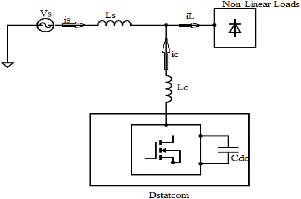
Figure 1: Schematic diagram of DSTATCOM
The capacitor acts as an active filter for stored energy. Due to the switching algorithm, energy can be transmitted from the Cdc to the inductor. The compensating principle of the DSTATCOM is constructed to compensate the current ic from supply to the load. Because of this ic, it eliminates the current harmonics and Q on the source side. Thus the source current (is) can be purely sinusoidal and in phase with source voltage (Vs).
The SRF control, commonly called DQ control, is primarily based on a reference frame transformation unit that converts the utility grid’s current and voltage characteristics to a synchronously rotating reference frame. The Clarke and Park transformation procedures, which convert abc to and DQ, are used to accomplish this transformation. The SRF control method is based on the current transformations in the d-q frame. Shunt Active Power Filter (APF) sensed the source voltage (Va, Vb, Vc). The PCC current (Ia, Ib, Ic) and the injected Va, Vb, Vc are in phase. These voltages and source current can be converted into D-Q, shown in Fig. 2. The below equations can give a better understanding of the operating controller.
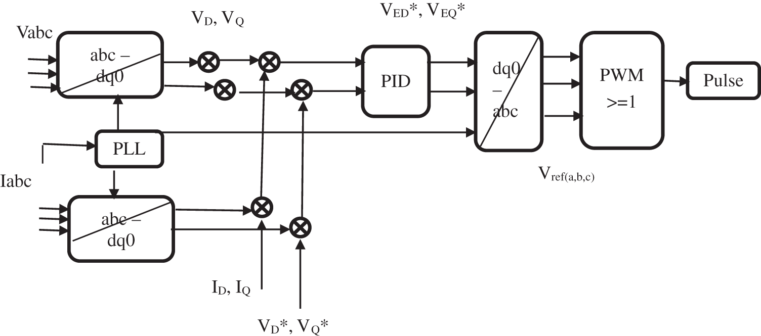
Figure 2: SRF control
where, the DQ axes are represented revolving with an angular velocity equal to, the same as the phase voltages and currents. VED and VEQ are the representation of rotating reference frame to a three-phase (abc) signal. The shunt APF signals are given to the PID controller to generate control signals, converted to the ABC domain for switching signals in PWM. It again provides the pulse to the shunt APF converter by synchronized decision.
The current components are generated in α-β coordinates using transformation angle θ. These can be transfers α-β to d-q frame is called the park’s transformation.
SRF control extracts the DC component of id and iq; further, the dc components are extraction of iddc and iqdc are transformed into an α-β frame, known as reverse park’s transformation.
The current transformation is obtained as iabc. The compensation of ‘Q’ can be provided as it is zero to calculate the reference source current iref,abc.
The function of DSTATCOM needs an AC supply to require real power (P) to the load and losses. So, the switching DSTATCOM is used to decide iref,abc by the load current component, which is extracted from SRF and the losses can be estimated using PID, Fuzzy-PID and ANN-PID control the DC link voltage (Vdc).
3.1 PID Control to Maintain the Vdc
A controller in a control system is a technique that attempts to reduce the difference between a system’s actual value (i.e., the process variable) and its desired value (i.e., the setpoint). All sophisticated control systems require controllers; these are critical points of control technique. The second-order active reference current is compared with reference Vdc* and sensed Vdc is a voltage error in nth sample Vdc(error,n), which is expressed below,
Vdc(error,n),which is progressed in PID control, the output Iout(n) in the nth sample,
where Kpdc, Kids, and Kddc are 1, 0.5 and 0.001 are the gains of the PID controller. The PID controller’s output is considered the current loss component of the DSTATCOM. This can be added to the d-axis of the current.
3.2 Fuzzy-PID Control to Maintain the Vdc
A Fuzzy-PID is used to regulate Vdc in DSTATCOM. The fuzzy rules are consequences of the knowledge of the system’s behavior, whereas mathematical modeling is needed to incorporate into the system. Capacitor voltage (Vc) and reference voltage (Vdref) are compared. Fuzzy control has the input variables like error (e) and change in error (
where α and β are the scaling factors of the input.
Then the
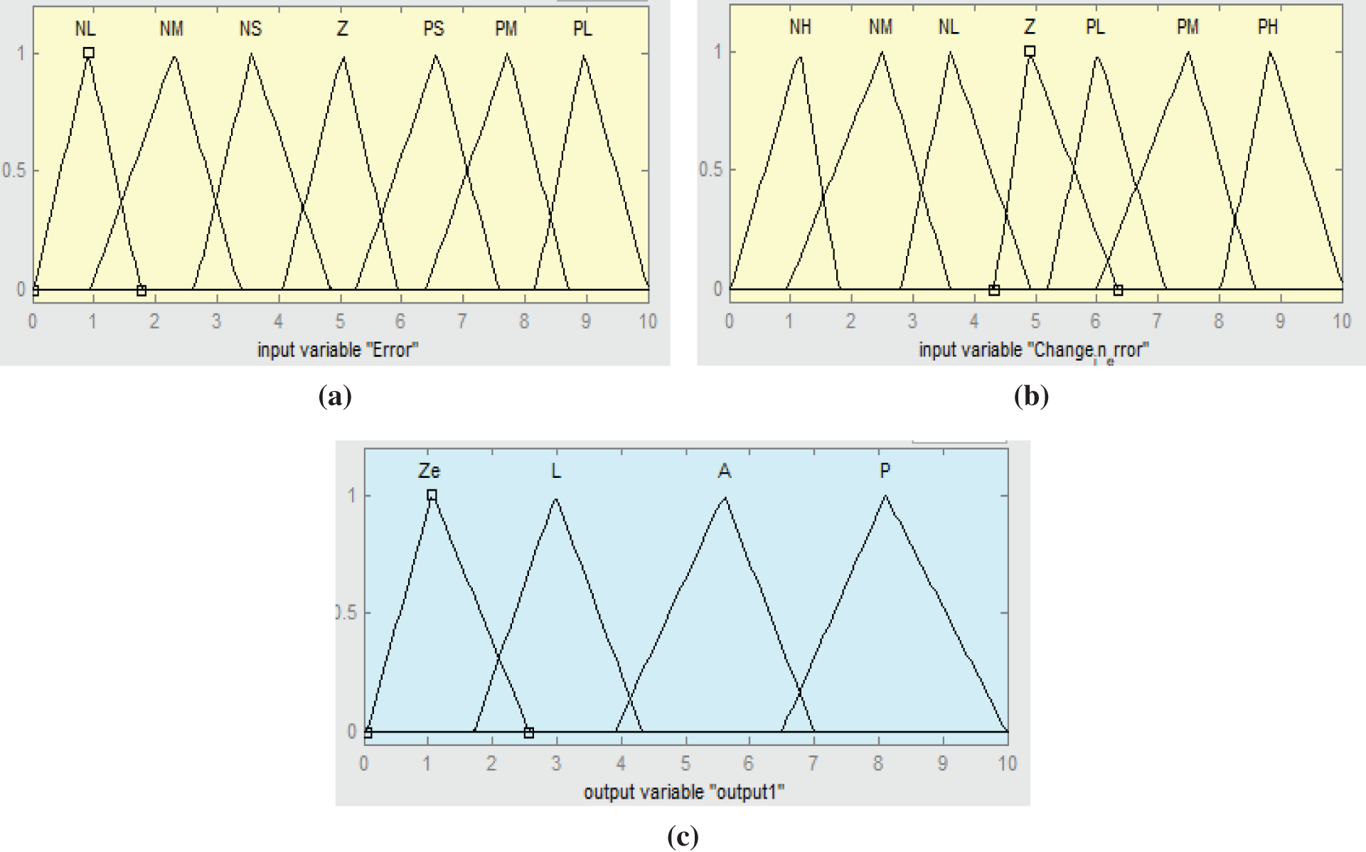
Figure 3: MFs of the fuzzy control (a) input variable 1, (b) input variable 2 and (c) output variable
The input MFs can ensure that the converter output voltage with the 49 rules is derived, as shown in Tab. 1.
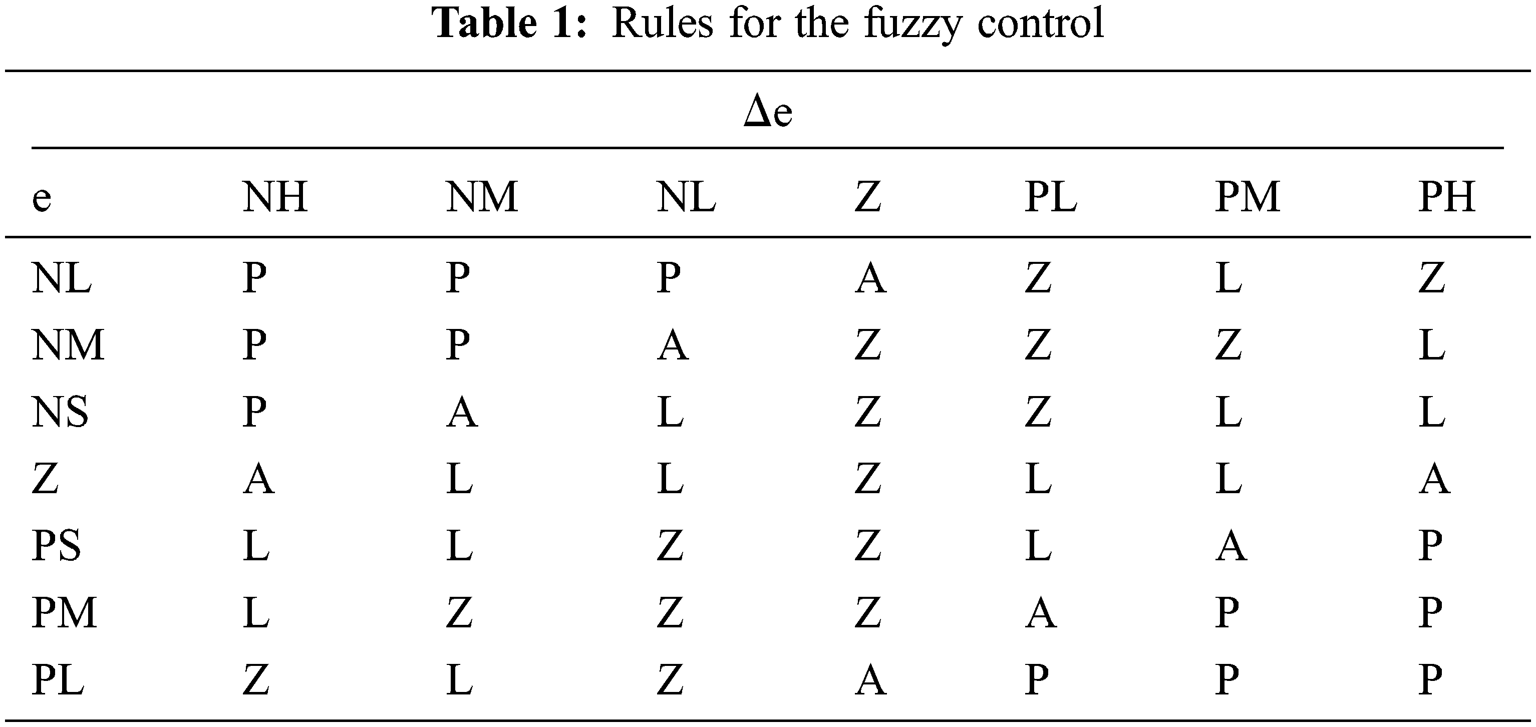
Then the attained values from fuzzy can be given to the PID control. It can be further tuned the required value to the DSTATCOM.
3.3 ANN-PID Control to Maintain the Vdc
In this ANN control, the data can be trained with initial inputs and targets from the presented system, as shown in Fig. 4. The input and output data were taken from the simulated DSTATCOM design with SRF control. The gained data can be imported to the input and targets in the nf tool. The data can be trained from the model of DSTATCOM implementation, which has been trained from the multi SRF technique.
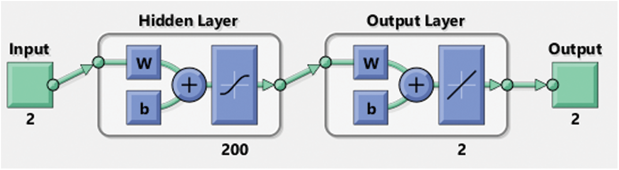
Figure 4: ANN tool for ANN control
Then select the samples in matrix rows. After that, validation and test data should be checked with 15% of 1810 samples of 2 inputs and 200 hidden layers of the neurons with two output layers. Finally, train the system.
The load can sense the reference current. Then the waveform can be expressed by Fourier analysis,
where Xn and Yn are the nth harmonics component of cos and sin amplitude,
The sample singles are arranged with a uniform rate (
Where,
Here the error e(k) can be expressed as,
The attained weight is used as the next iteration W(k+1) to minimize the (k). Likewise, the iteration can be processed until the actual signal can be attained from estimated signals. Then the estimated signal can be given to the PID control to tune the gained values further to regulate the Vdc of the DSTATCOM.
4 Simulation Model of DSTATCOM System
The simulation of the DSTATCOM system is designed using MATLAB/Simulink in the Simscape platform, which is shown in Fig. 5. This simulation can be configured with a three-phase source, DSTATCOM, Controllers and load. The Non-linear load is considered the load consisting of the universal bridge, resistance (R) and inductance (L) integrated into series and parallel with each phase. The three-phase source is 400 V and 50 Hz, the universal bridge with three bridge arms, and the series-connected R and L are 50 Ω and 200 mf, respectively. Then the parallel-connected R1, R2 and R3 are 30, 40 and 50 Ω, respectively. Also L1, L2 and L3 are 0.1999, 0.2499 and 0.1599 H, respectively. In the VSC, a capacitor is used to store the energy with the rating of 2600 µF, and MOSFET is used as a switch. Then Rf and Lf are connected with the range of 1 Ω and 120 mH, respectively.
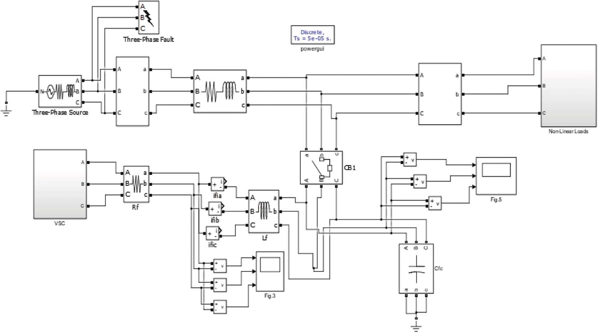
Figure 5: Simulation diagram of DSTATCOM
The simulated SRF control is shown in Fig. 6. This SRF model is designed by mathematical blocks of the Simulink. The simulation is conducted in the continuous mode at the largest step size. Because the templates use Phase Locked Loop (PLL), PPL is an electronic circuit that uses a voltage or voltage-driven oscillator to match the input signal frequency by adjusting constantly. It is a frequency and phase-sensitive closed-loop feedback control circuit that provides an output signal with a phase relationship to its input. The two signals will have the same frequency and then either no or a continuous phase difference among them. PLL adjustment is required. The operation of a PLL is slower, so it introduces some delayed computations. DSTATCOM performs on self-supporting Vdc, which is kept at 250 V. At t = 0.4–0.6 s, the impact of a load change is observed.

Figure 6: Simulation diagram of SRF control
In the sub-system of the voltage stabilizer, Controllers are designed to control the Vdc, Vref and capacitive DC are the source. The estimated values are given to the Id,loss. Whereas the proposed implemented controllers are shown in Fig. 7.
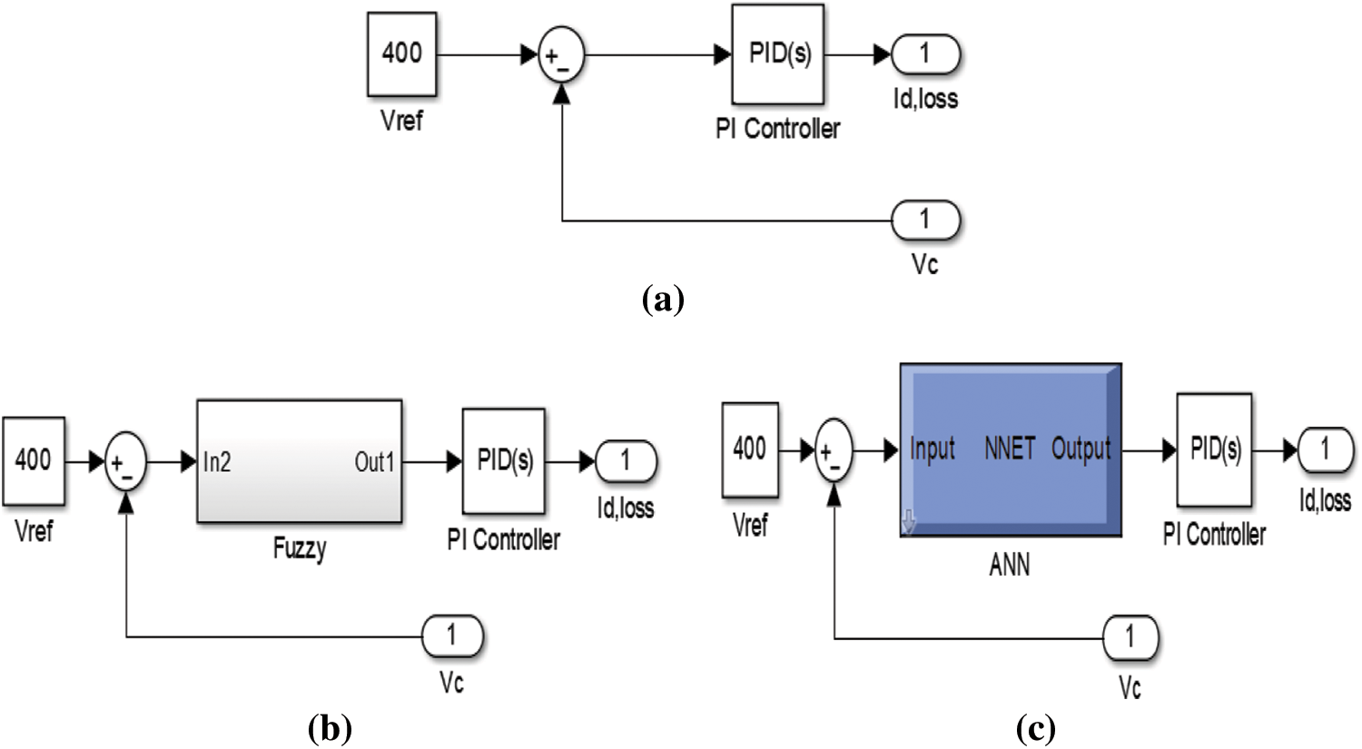
Figure 7: Simulation blocks of controllers (a) PID, (b) Fuzzy-PID, (c) ANN-PID
The DSTATCOM-based SRF control method is designed with soft computing techniques of Fuzzy-PID and ANN-PID. The results follow the observations. An Implementation of a short-circuit fault either between phase and ground. Whenever the exterior switching time mode is nominated, the fault action is controlled by a Simulink logical signal. The fault of switching time is at 0.4 to 0.6 s. At the same time, the Vs and Is are attained from the presented DSTATCOM-based SRF control method shown in Fig. 8.

Figure 8: Vs and Is of the DSTATCOM based SRF
Fig. 8 illustrates the Vs and Is, which means without compensation. The Vs and Is are 300 V and 11 A, respectively. At the fault period, the Vs and Is can be unbalanced. So the voltage can be decreased from 300 to 250 V and the current is unbalanced from 11 to 60 A. Fig. 9 shows the received accurate results in voltage and current waveform magnitude.

Figure 9: P and Q of the DSTATCOM based SRF without compensation
The voltage is decreased and the current is increased due to the inductive nature of the load, which receives a significant amount of power from the supply side. Also, the system’s P is increased from 5.7 to 12 kW and Q is decreased from 3.2 to −10 kVAR at 0.4 to 0.6 s because of the unbalances.
The dynamics are displayed in reverse order after 0.6 s. IL waveforms show a delay in compensating. The Low Pass Filter (LPF) causes this delay used to filter power signals. An LPF has a cut-off frequency that determines which frequencies are allowed to pass and which are filtered. A signal component would pass if its frequency is less than the cut-off frequency, or it would be filtered. These filters are employed to reduce circuit noise. When a sound is sent via LPF, most of the noise is eliminated, leaving a clean sound. Furthermore, SRF theory-based PID computes instantaneous P and Q using voltage signals. Any voltage distortion or unbalance will consequence in an incorrect computation of iref,abc should only include the true fundamental frequency component of the current of the load.
Fig. 10 shows that the DSTATCOM-based SRF uses PID control; this waveform represents the VL, IL, P and Q. At 0.4 s, the load was raised from 300 to 350 V, and the unbalance was introduced at 0.4 s. This waveform shows the compensation of the voltage and current due to the injection of Q by the DSTATCOM. In compensation, P is 5.5 to 7 kW with a slight peak at 0.45 s; Q is 2.4 to 1.6 kVAR at 0.4 to 0.6 s.
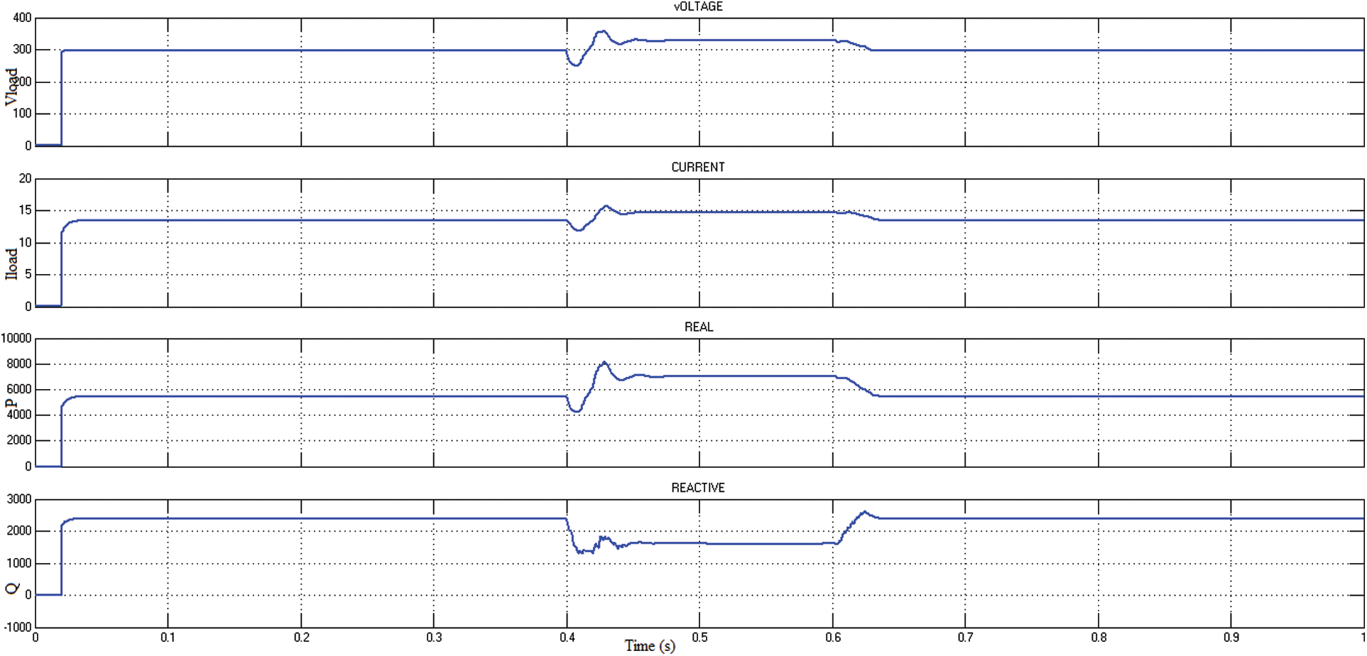
Figure 10: Waveform of DSTATCOM based SRF using PID
After that, a Fuzzy-PID controller is proposed to control the unbalances. Simultaneous load adjustments and imbalanced circumstances are simulated as in the preceding scenario. The extracted reference current waveform shows the influence of delay caused by the LPF utilized in the DQ frame signal filtering. The development of voltage is essential in calculating iref,abc.
Fig. 11 presents the magnitude of the voltage, current, P and Q. This waveform differs from the unbalances by using a PID controller, because, this Fuzzy-PID is pretty more accurate. The magnitude of the voltage and current can be balanced due to the injection of Q at corresponding ranges of 300 V and 13.5 A.
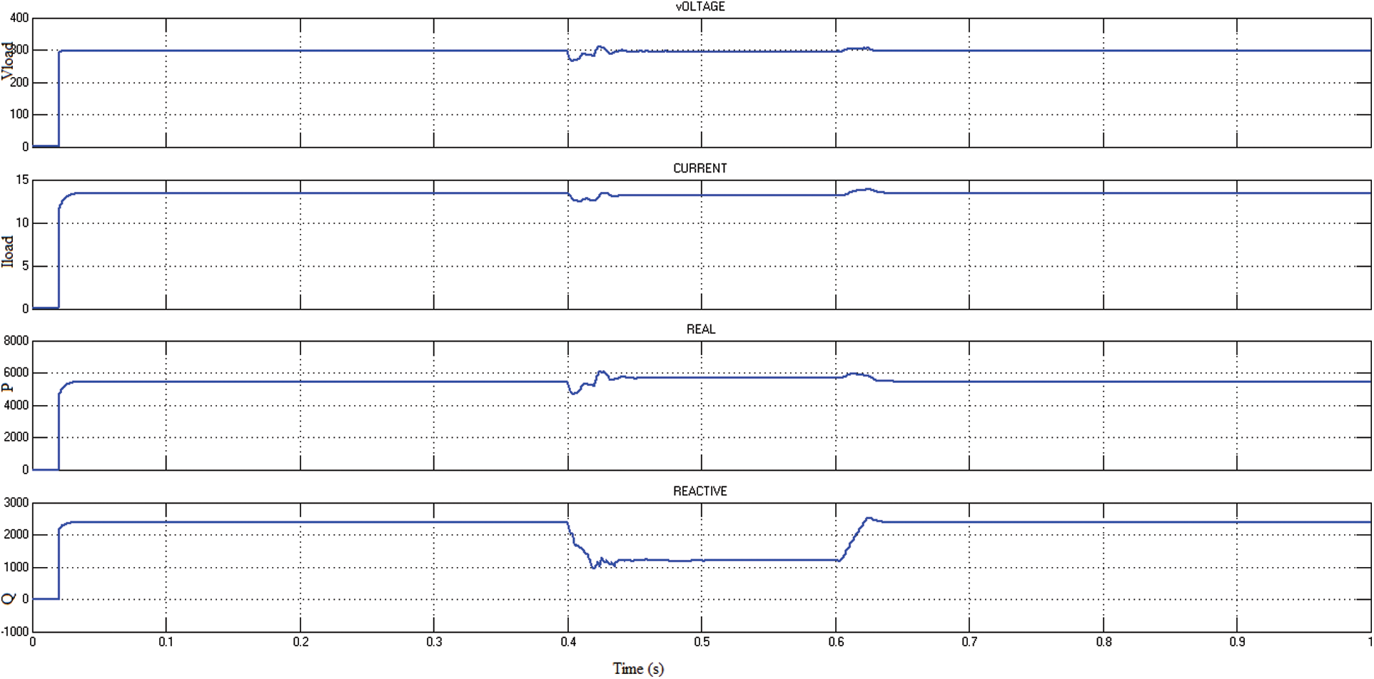
Figure 11: Waveform of DSTATCOM based SRF using Fuzzy-PID controller
The ANN-PID extractor has the benefit of requiring less computing effort, making implementation of this approach considerably simpler. Furthermore, ANN-PID has intrinsic linearity which is the models having non-linear parameters, but they can be converted into linear regression models with the appropriate transformation that enables it to a quick solution. Fig. 12 depicts DSTATCOM’s utilizing ANN-PID.
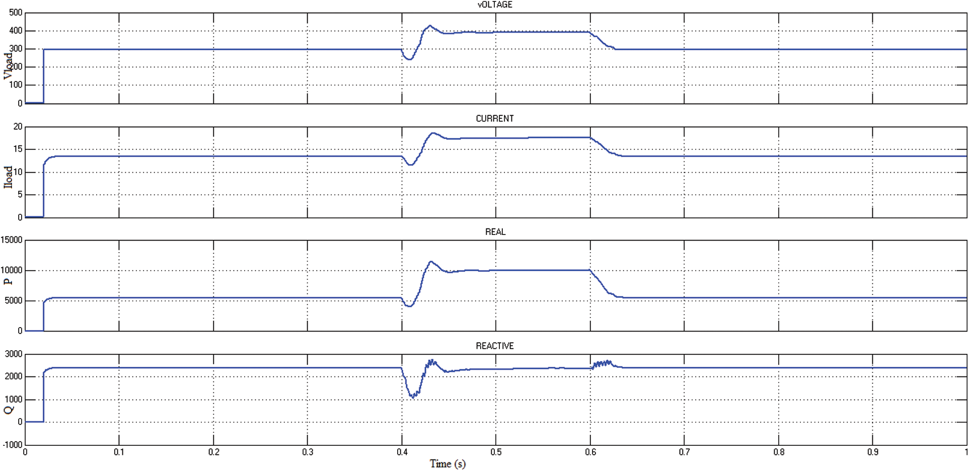
Figure 12: Waveform of DSTATCOM based SRF using ANN-PID controller
It can be seen that DSTATCOM with SRF-based ANN-PID is sufficient to meet load fluctuations within a one sine wave. Using this technique, the unbalance load voltage is compensated from 250 to 310 V at 0.4–0.6 s. Likewise, the load current also compensated from 60 to 11 A at 0.4–0.6 s. Here the injection of Q is 2.4 to 2.2 kVAR. In this technique, the Q injection is low than in other techniques, which shows that the voltage and current are balanced and maintain the power quality, which leads to a unity power factor. If the power factor is lesser than one, then the load current will be higher and so the unity power factor is maintained. It also prevents transformers, motors, and other electrical components from overheating. The unity power factor develops even though there is no phase shift across voltage and current or when they are both in the same phase. When the power factor is one, the primary power source is doing beneficial work. In this situation, no electricity is being wasted. Shallow losses occur at the unity power factor. Whereas the system can be stable at the unity power factor, due to power quality issues, the system may unbalance, which is explained above, which leads to 0.8 PF.
Fig. 13 shows that the power factor, the first waveform represents that the without compensated unbalanced system’s PF is 0.8, mainly at the fault time the PF is further reduced. After compensation of the unbalanced load, PF is 1 and still 1 PF at 0.4 to 0.6 s. Comparative THD analysis of the DSTATCOM-based SRF using various controllers.

Figure 13: PF of the presented model
Total harmonic distortion (THD) is a measurement that indicates the voltage or current distortion caused by harmonics in the signal. It is defined as the ratio of the total of all harmonic components’ powers to the fundamental frequency’s power. Fig. 14 illustrates the THD analysis of the DSTATCOM-based SRF using soft computing techniques. The waveform shows that ANN-PID control has low harmonics, among other methods. PID control has more THD%, which is a conventional technique.

Figure 14: Comparative analysis of THD%
Improving power quality is essential because of the increasing use of electronic devices more vulnerable to electrical interference. This article recommended implementing DSTATCOM to enhance power quality in the distribution system. The SRF control, which is time domain-based, is presented here. Furthermore, soft computing approaches such as Fuzzy-PID and ANN-PID are proposed to improve power quality concerns. The proposed controllers are compared to classic PID, Fuzzy, and ANN controllers. The proposed system is simulated in MATLAB/Simulink, demonstrating that the DSTATCOM-based SRF has a rapid reaction and precise load adjustment utilizing Fuzzy-PID and ANN-PID controllers. It is observed that DSTATCOM-based SRF with ANN-PID control offers THD of 1.48%. To overcome the complexity of the presented system, the future scope of this work is to mitigate the power quality issue using Genetic Algorithm (GA)-PID control and metaheuristic optimization techniques for more effectiveness.
Funding Statement: The authors received no specific funding for this study.
Conflicts of Interest: The authors declare that they have no conflicts of interest to report regarding the present study.
References
1. M. Rastogi, A. Ahmad and A. H. Bhat, “Performance investigation of two-level reduced-switch D-STATCOM in grid-tied solar-PV array with stepped P&O MPPT algorithm and modified SRF strategy,” Journal of King Saud University-Engineering Sciences, pp. 1–13, 2021. [Google Scholar]
2. A. Venkata Suresh and B. VenkataPrasanth, “Design of neural network controlled DSTATCOM using SRF algorithm to improve power quality,” International Journal of Engineering Research & Technology, vol. 2, no. 8, pp. 1–8, 2013. [Google Scholar]
3. V. Ganji, D. Suresh and K. Chandrasekhar Koritala, “Adaptive neural network-based LMS for DSTATCOM,” Innovations in Electronics and Communication Engineering, vol. 65, pp. 159–166, 2019. [Google Scholar]
4. E. A. Al-Ammar, A. Ul-Haq, A. Iqbal, M. Jalal and A. Anjum, “SRF based versatile control technique for DVR to mitigate voltage sag problem in the distribution system,” Ain Shams Engineering Journal, vol. 11, no. 1, pp. 99–108, 2020. [Google Scholar]
5. S. Vinnakoti and V. R. Kota, “ANN-based control scheme for a three-level converter based unified power quality conditioner,” Journal of Electrical Systems and Information Technology, vol. 5, no. 3, pp. 526–541, 2018. [Google Scholar]
6. M. Bajaj, M. Pushkarna, A. S. Rana and M. T. Khan, “An improved SRF based control algorithm for D-STATCOM under abnormal source voltage,” in Annual IEEE India Conference, New Delhi, India, pp. 1–6, 2015. [Google Scholar]
7. K. Swetha and V. Sivachidambaranathan, “A review on different control techniques using DSTATCOM for distribution system studies,” International Journal of Power Electronics Drives & Systems, vol. 10, no. 2, pp. 813–21, 2019. [Google Scholar]
8. S. B. Pandu, C. K. Sundarabalan, N. S. Srinath, T. S. Krishnan, G. S. Priya et al., “Power quality enhancement in sensitive local distribution grid using interval type-II fuzzy logic controlled DSTATCOM,” IEEE Access, vol. 12, no. 9, pp. 59888–59899, 2021. [Google Scholar]
9. R. Pandiaraj, “Enhancement of power quality using fuzzy logic controlled DSTATCOM,” International Journal of Advances in Signal and Image Sciences, vol. 6, no. 1, pp. 21–28, 2020. [Google Scholar]
10. S. R. Reddy, P. V. Prasad and G. N. Srinivas, “Design of PI and fuzzy logic controllers for distribution static compensator,” International Journal of Power Electronics and Drive Systems, vol. 9, no. 2, pp. 465–477, 2018. [Google Scholar]
11. P. Kanirajan and M. Joly, “Modelling of DSTATCOM for improving power quality using ANN controller by fuzzy C-means clustering,” International Journal of Power Systems, vol. 4, pp. 465–477, 2019. [Google Scholar]
12. S. Karuna and P. V. Prasad, “Power quality improvement by using DSTATCOM with PSO tuned PI controller,” International Research Journal of Engineering and Technology, vol. 6, no. 7, pp. 2219–2228, 2019. [Google Scholar]
13. R. A. Mejeed, A. K. Jameil and H. I. Hussein, “Harmonic amplification damping using a DSTATCOM-based artificial intelligence controller,” International Journal of Sensors Wireless Communications and Control, vol. 9, no. 4, pp. 521–530, 2019. [Google Scholar]
14. E. Ramakrishna, “Adaptive RNN with CSOA controlled based MMC-DSTATCOM for PQ enhancement in distribution system,” Turkish Journal of Computer and Mathematics Education, vol. 12, no. 2, pp. 876–888, 2021. [Google Scholar]
15. A. A. Nafeh, A. Heikal, R. A. El-Sehiemy and W. A. Salem, “Intelligent fuzzy-based controllers for voltage stability enhancement of AC-DC micro-grid with D-STATCOM,” Alexandria Engineering Journal, vol. 61, no. 3, pp. 2260–93, 2022. [Google Scholar]
16. S. Dey, “Comparison of DVR and D-STATCOM for voltage quality improvement,” International Journal of Emerging Technology and Advanced Engineering, vol. 4, no. 10, pp. 187–93, 2014. [Google Scholar]
17. L. Cristaldi, A. Ferrero and S. Salicone, “A distributed system for electric power quality measurement,” IEEE Transactions on Instrumentation and Measurement, vol. 51, no. 4, pp. 776–81, 2002. [Google Scholar]
Cite This Article
 Copyright © 2023 The Author(s). Published by Tech Science Press.
This work is licensed under a Creative Commons Attribution 4.0 International License , which permits unrestricted use, distribution, and reproduction in any medium, provided the original work is properly cited.
 Downloads
 Citation Tools