
 Submit a Paper
 Propose a Special lssue
 Open Access
ARTICLE

Analysis of Power Quality for Distribution Networks Using Active Compensator
1 R. M. K. Engineeirng College, Chennai, Tamilnadu, India
2 Velammal Engineering College, Chennai, Tamilnadu, India
* Corresponding Author: K. Naresh Kumar. Email:
Intelligent Automation & Soft Computing 2023, 36(3), 2623-2638. https://doi.org/10.32604/iasc.2023.031713
Received 25 April 2022; Accepted 08 September 2022; Issue published 15 March 2023
 View Full Text
 Download PDF
Abstract
This paper concentrates on compensating the power quality issues which have been increased in day-to-day life due to the enormous usage of loads with power electronic control. One such solution is compensating devices like Pension Protection Fund (PPF), Active power filter (APF), hybrid power filter (HPF), etc., which are used to overcome Power Quality (PQ) issues. The proposed method used here is an active compensator called unified power quality conditioner (UPQC) which is a combination of shunt and series type active filter connected via a common DC link. The primary objective is to investigate the behavior of the compensators in the distribution networks. The performance of two configurations of UPQC, Right Shunt UPQC (RS-UPQC) and Left Shunt UPQC (LS-UPQC) are tested in the distribution networks under various load conditions by connecting them at the source side of harmonic generation using a specially constructed transformer called inductively filtered converter transformer which adopts special wiring scheme at the secondary side. PSCAD (Power Systems Computer Aided Design)/EMTDC (Electromagnetic Transients with DC Analysis) software is used to model the compensators connected to the nonlinear load. Both RS-UPQC and LS-UPQC are tested at the distribution side of the supply system with Hysteresis current controller for shunt and Sinusoidal pulse with modulation controller for series at various locations of power system network and their results are compared.Keywords
TERMINOLOGY
| PQ | Power Quality |
| L-UPQC | Left Shunt UPQC |
| DC | Direct Current |
| PCC | Point of Common Coupling |
| SAF | Shunt Active Filter |
| TCT | Traditional Converter Transformer |
| NCT | New Converter Transformer |
| IAF | Inductive Active Filtering |
| PPF | Passive Power Filter |
| PWM | Pulse Width Modulation |
| PLL | Phase Locked Loop |
| VSC | Voltage Source Converter |
| Is | Source Current |
| IL | Current form the nonlinear load |
| IP | Primary current of the Transformer |
| IF | Current output from the SAF |
A smooth supply to the consumers is provided by mitigating the power quality issues and making use of the energy efficiently at the consumer terminals. Power Quality is a major concern for the past few years because the linear loads in the power system network have been replaced by the power electronics loads. It is because of the increased usage of nonlinear loads by consumers all over the world. Some of the loads like Light Emission Diode (LED)s, electric drives, uninterruptible power supply (UPS), arc furnaces, etc. draw harmonic currents from the integrated supply network thereby acting as a nonlinear load. Therefore these nonlinear loads present in the supply network affect the quality of power by introducing a wide range of harmonics that will affect the performance of the connected devices. To suppress the magnitude of harmonics, proper compensation has to be provided in the supply network. These compensations in the network can be provided to a wide range of devices from Passive filters, active filters from hybrid active filters of the shunt, series, and type types to unified power quality conditioning [1–5].
When connecting the compensation devices it has the following concerns. A passive LC filter (inductors (L) and capacitors (C)) in the network can reduce only the fixed order harmonics and the series/parallel resonance is the major issue that occurs between the LC filter and system impedance. And when it happens this will increase harmonic voltages and currents and finally it may damage the LC filter and nearby equipment [6–8]. Shunt active filter is connected in shunt fashion to Point of Common Coupling (PCC) point to track the online changes in the order of harmonic generation in the supply network by using To create the exact opposite features to a control algorithm in order to balance it But in this instance, the problem shunt active filter is only used to address current quality concerns and also fails to preserve the grid current’s power factor [9].
The series active filter is connected in series with the supply network via the series transformer in order to handle voltage quality issues like sag and swell. The advantages of both active and passive filters are shared by a hybrid active filter, which lowers the inverter’s rating and investment costs while combining a Shunt Active Filter (SAF) with a passive LC filter. Again, in this instance, devices are made specifically for current correction, not for voltage issues [10]. Therefore, designers implemented UPQC in the distribution system to enhance the quality of the power and guarantee a steady supply to the customers. The shunt and series active filters are coupled in the UPQC device to solve both current- and voltage-related issues using a single DC link in the supply network [11–13].
To restrict the flow area of harmonics a specially constructed transformer called a new converter transformer is made to integrate the compensating device at the harmonic generating source side itself, which in turn reduces the harmonic distribution area and thereby reduces all the difficulties created by harmonic currents at the source site itself. And at last, the cost, size complexity of the design, and insulation difficulty are reduced [14–17].
The remainder of the paper is organized as follows: Section 1 explains the UPQC technique. Section 2 explains the control strategy used for the active compensator. Section 3 illustrates the Filtering presentation and the physical characteristics of proposed and existing methodologies. Section 4 results and identify the power quality improvement and the conclusion is depicted in Section 5.
In any nonlinear network to solve the integrated issues of voltage and current, we connected the two active devices one in series and the other one in shunt fashion in a back-to-back manner and they are shared by a common direct current (DC) link between them are shown in Fig. 1. The common devices used in UPQC are:

Figure 1: Proposed configuration of UPQC incorporated in NCT
Shunt Active Filter
A voltage source inverter with parallel connections serves as a shunt active filter. It is suggested that the current quality issues can be resolved by canceling out the current harmonics that the nonlinear load produces. A Control scheme is used to track the harmonic features and deliver the exact opposite harmonic qualities as compensation. It was also advantageous to keep the capacitor’s DC voltage stable.
Series Active Filter
A series-connected voltage source inverter functions as a series active filter. A series transformer is used to connect it to the system. By minimizing voltage imbalances and flickers in the output voltage, this series filter is employed to moderate the voltage fluctuation generated in the system and to preserve a sinusoidal voltage waveform. The series inverter is controlled by a hysteresis controller.
DC Link
A capacitor is used between the two voltage source converters, and it is shared by the inverter and the converters as well. A constant voltage must be produced across the capacitor in order for filters to operate effectively. If the capacitor voltage is properly managed, the need for batteries can be eliminated; but, if it is not, the capacitor voltage may vary, preventing the filters from effectively carrying out their duties. The capacitor voltage is maintained constant using the PI control strategy since it is simple.
A series active filter is connected in line with a series transformer to reduce the current entering the series inverter. Therefore, in order to maintain the load voltage, the sinusoidal voltage must be generated at a certain level alone by the series active filter. An RC filter is connected across with a series transformer at the secondary side in order to reduce the significant amount of ripple content caused by switching in the inverter’s injected voltage. Fig. 1 UPQC’s proposed layout as it relates to NCT.
In order to maintain stable load voltage, which is often needed for the sensitive load in the power system network, Fig. 2 illustrates the series controller implemented in the compensator. The phase and amount of the voltage injected by the series active power filter may be controlled by altering the switching order of the series inverter. The phase-locked loop receives the voltage from the three-phase voltage source to produce the reference waveform. By comparing the voltages at the primary side of the transformer with the load voltage, these reference signals from the series compensator are acquired. The controller for the series compensator creates the necessary gate signals for the voltage source converter by acquiring these signals (VSC).

Figure 2: Controller for series active filter
The active compensator’s shunt section makes up for the load current. Fig. 3 illustrates how the voltages acquired at the Point of Common Coupling are used by a Phase Locked Loop (PLL) to create the unit vector templates (PCC). The phase angle for reference currents is generated via PLL. The correct phase-shifted PLL output is acquired to provide the sinusoidal reference source currents. The PI controller here provides the magnitude of the sinusoidal reference source current. The primary source current required to charge the DC link capacitor is ascertained by comparing the DC-link voltage measurements to a reference value. Researchers can generate the switching pulses for the shunt-connected Active power filter using the hysteresis controller by comparing currents with reference values.

Figure 3: Controller for shunt active filter
To prove the performance of the compensator design we have categorized the work into different configurations to compare their results and identify the best solution for power quality improvement. First, simulated the uncompensated system in that we measured the harmonic contents in voltage and current waveforms which have been depicted in Fig. 4.

Figure 4: Uncompensated system voltage and current waveforms
Next, we connect the shunt active filter at the primary side of the TCT – Traditional Converter Transformer and the results of both the current and voltage of the compensated system are shown in Figs. 5 and 6.

Figure 5: TCT with shunt active filter current waveforms
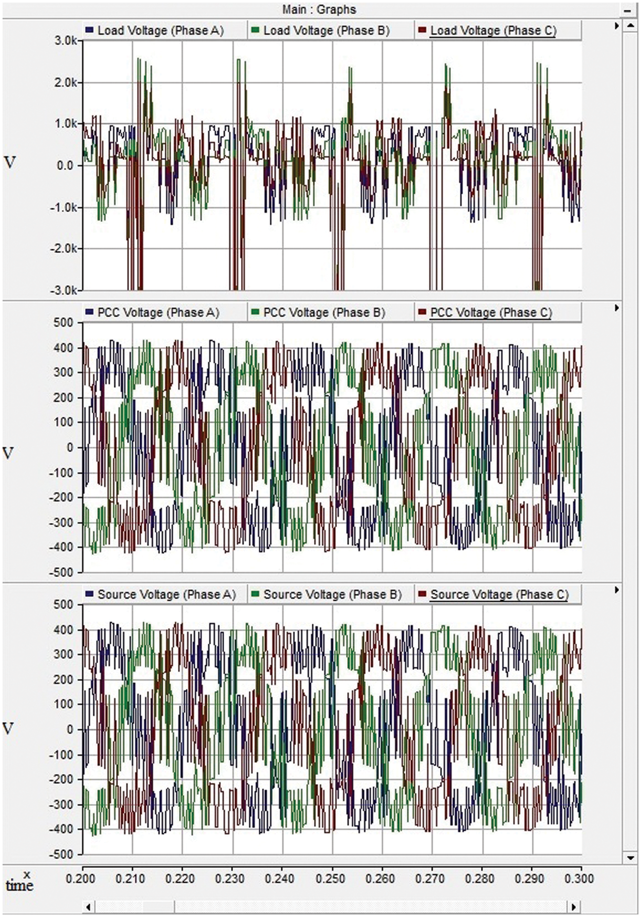
Figure 6: TCT with shunt active filter voltage waveforms
At the third configuration, we replaced our converter transformer of traditional into a new one called NCT, which is having a connection node to connect to the compensating device. Shunt Active Power Filter (SAF) at the secondary side of harmonic generating source side, their results of current and voltage and current waveforms are shown in Figs. 7 and 8.

Figure 7: NCT with shunt active filter current waveforms
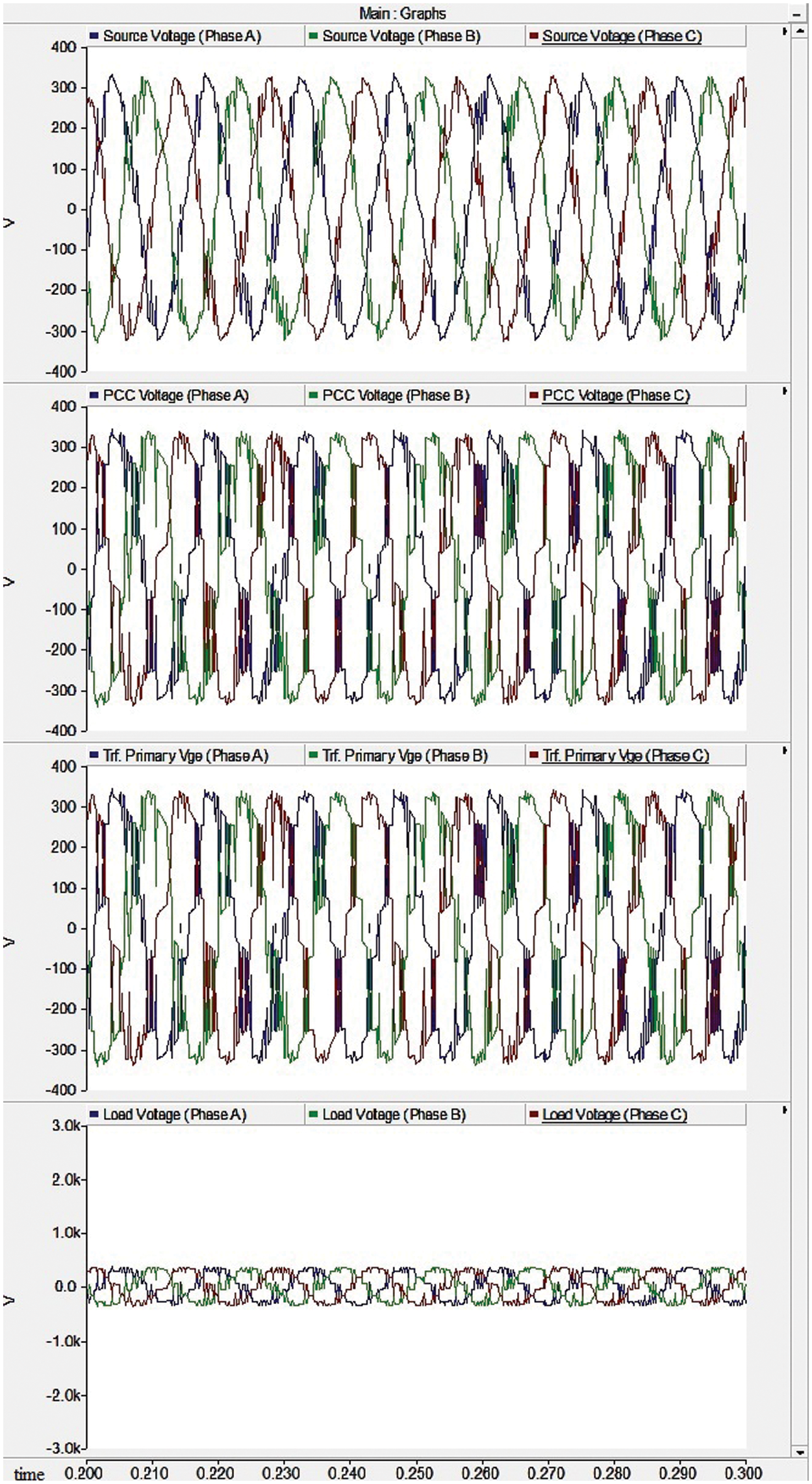
Figure 8: NCT with shunt active filter voltage waveforms
The previous configuration is used to reduce the harmonic content only in the current portion but not in the voltage portion. To compensate for the harmonic content both in voltage and current we used the active compensator called Unified Power Quality Conditioner (UPQC) in the NCT. Under this we have taken two configurations of UPQC one is Right shunt UPQC their behavior of current and voltage waveforms are illustrated in Figs. 9 and 10.
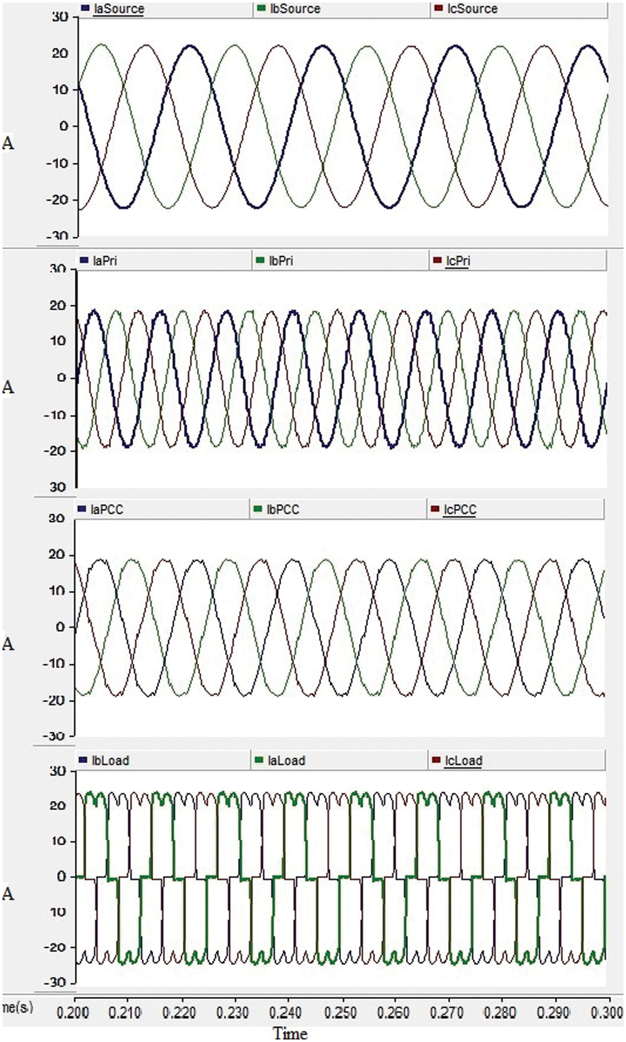
Figure 9: NCT with RSUPQC current waveforms

Figure 10: NCT with RSUPQC voltage waveforms
Other configurations of UPQC have Left shunt UPQC their behavior when it incorporates the secondary side of NCT is depicted in Figs. 11 and 12.

Figure 11: NCT with LSUPQC current waveforms

Figure 12: NCT with LSUPQC Voltage Waveforms
Table 1 shows the total harmonic distortion (THD) comparison in various system components using various compensator setups connected.

This paper implemented a secondary side of a modern converter transformer that uses inductive filtering and has a uniform power quality state. This configuration is used in distribution networks to reduce harmonic content, which enhances the supply system’s power quality. The compensating device is connected to the secondary side of the new converter transformer using a shared linkage mechanism and a two-winding arrangement. The harmonic content at the secondary side of NCT is balanced by using the controller for the compensator, which is designed using the mathematical model. The power network’s harmonic analysis of various configurations in various places is examined. Based on the analysis of the simulation results, it can be concluded that the configuration of NCT with RS-UPQC will perform better than NCT with LS-UPQC in terms of harmonic reduction with respect to both voltage- and current-related issues, to balance out unbalanced conditions like sag and swell, and to enhance the voltage profile of the system. The active compensator adopted in the distribution networks at the harmonic sources side using NCT can greatly reduce the rating and size of the transformer by improving the filtering effects at the source side itself as a result cost of the system will greatly be reduced.
Funding Statement: The authors did not receive any special funding for this study.
Conflicts of Interest: The authors certify that they have no competing interests in relation to this research.
References
1. Y. Li, L. Luo, C. Rehtanz, C. Wang and S. Rüberg, “Simulation of the electromagnetic response characteristic of an inductively filtered HVDC converter transformer using field-circuit coupling,” IEEE Transactions on Industrial Electronics, vol. 59, no. 11, pp. 4020–4031, 2012. [Google Scholar]
2. Y. Li, L. Luo, C. Rehtanz, K. Nakamura, J. Xu et al., “Study on characteristic parameters of a new converter transformer for HVDC systems,” IEEE Transactions on Power Delivery, vol. 24, no. 4, pp. 2125–2131, 2012. [Google Scholar]
3. H. Akagi and K. Isozaki, “A hybrid active filter for a three-phase 12-pulse diode rectifier used as the front end of a medium-voltagemotor drive,” IEEE Tranactions on Power Electron, vol. 27, no. 1, pp. 69–77, 1998. [Google Scholar]
4. Y. Li, L. Luo, C. Rehtanz, S. Rüberg, D. Yang et al., “An industrial DC power supply system based on an inductive filtering method,” IEEE Tranactions on Industrial Electron, vol. 59, no. 2, pp. 714–722, 2012. [Google Scholar]
5. Y. Li, L. F. Luo, S. Rüberg, C. Rehtanz, D. C. Yang et al., “A class of new HVDC transmission modes improved by inductive filtering method,” in Proc. of 2010 Int. Conf. on Power System Technology (POWERCON 2010Zhejiang, Hangzhou, China, pp. 24–28, 2010. [Google Scholar]
6. K. M. S. Khadem, M. Basu and F. Michael Conlon, “UPQC for power quality improvement in DG integrated smart grid network—A review,” International Journal of Emerging Electric Power Systems, vol. 13, no. 3, pp. 50–60, 2012. [Google Scholar]
7. Y. Li, T. K. Saha, O. Krause, Y. Cao and C. Rehtanz, “An inductively active filtering method for power-quality improvement of distribution networks with nonlinear loads,” IEEE Transactions on Power Delivery, vol. 28, no. 4, pp. 2465–2473, 2013. [Google Scholar]
8. L. Luo, Y. Li, J. Xu, J. Li, B. Hu et al., “A new converter transformer and a corresponding inductive filtering method for HVDC transmission system,” IEEE Transactions on Power Delivery, vol. 23, no. 3, pp. 1426–1432, 2008. [Google Scholar]
9. K. N. Kumar and S. Srinath, “Integration of UPQC with new converter transformer for power quality improvement,” in National Power Engineering Conf. (NPEC), Tiruparankundram, Madurai, Tamilnadu, pp. 1–6I, 2018. [Google Scholar]
10. O. Abdoli, E. Gholipour and R. A. Hooshmand, “A new approach to compensating voltage unbalance by UPQC-based PAC,” Electric Power Components and Systems, vol. 46, no. 3, pp. 1834–1840, 2018. [Google Scholar]
11. S. B. Shahapure and R. P. Hasabe, “Power quality improvement using unified power quality conditioner with distribution generation,” in Proc. of the Fourth Int. Conf. on Communication and Electronics Systems, Ranchi, India, pp. 1834–1840, 2019. [Google Scholar]
12. B. G. Lemma and M. Liao, “Active impedance-based single-phase hybrid active power filter,” IEEJ Transactions on Electrical and Electronic Engineering, vol. 14, no. 9, pp. 1381–1388, 2019. [Google Scholar]
13. K. Hasan, M. M. Othman, N. F. A. Rahman, M. A. Hannan, I. Musirin et al., “Significant implication of unified power quality conditioner in power quality problems mitigation,” International Journal of Power Electronics and Drive System (IJPEDS), vol. 10, no. 4, pp. 2231–2237, 2019. [Google Scholar]
14. V. V. N. Reddy, D. A. Kumar and V. R. Kota, “A multilevel UPQC for voltage and current quality improvement in distribution system,” International Journal of Power Electronics and Drive System (IJPEDS), vol. 10, no. 4, pp. 1932–1943, 2019. [Google Scholar]
15. C. R. Rathish and A. Rajaram, “Efficient path reassessment based on node probability in wireless sensor network,” International Journal of Control Theory and Applications, vol. 34, pp. 817–832, 2016. [Google Scholar]
16. C. R. Rathish and A. Rajaram, “Sweeping inclusive connectivity based routing in wireless sensor networks,” ARPN Journal of Engineering and Applied Sciences, vol. 3, no. 5, pp. 1752–1760, 2018. [Google Scholar]
17. A. Rajaram and K. Sathiyaraj, “An improved optimization technique for energy harvesting system with grid connected power for green house management,” Journal of Electrical Engineering & Technology, vol. 7, no. 5, pp. 1–3, 2022. [Google Scholar]
Cite This Article
 Copyright © 2023 The Author(s). Published by Tech Science Press.
This work is licensed under a Creative Commons Attribution 4.0 International License , which permits unrestricted use, distribution, and reproduction in any medium, provided the original work is properly cited.
 Downloads
 Citation Tools