
 Submit a Paper
 Propose a Special lssue
 Open Access
ARTICLE

Multi-Level Inverter Linear Predictive Phase Composition Strategy for UPQC
M. Kumarasamy College of Engineering, Karur, 639113, Tamil Nadu, India
* Corresponding Author: M. Hari Prabhu. Email:
Intelligent Automation & Soft Computing 2023, 36(3), 2947-2958. https://doi.org/10.32604/iasc.2023.032328
Received 14 May 2022; Accepted 26 August 2022; Issue published 15 March 2023
 View Full Text
 Download PDF
Abstract
The power system is facing numerous issues when the distributed generation is added to the existing system. The existing power system has not been planned with flawless power quality control. These restrictions in the power transmission generation system are compensated by the use of devices such as the Static Synchronous Compensator (STATCOM), the Unified Power Quality Conditioner (UPQC) series/shunt compensators, etc. In this work, UPQC’s plan with the joint activity of photovoltaic (PV) exhibits is proposed. The proposed system is made out of series and shunt regulators and PV. A boost converter connects the DC link to the PV source, allowing it to compensate for voltage sags, swells, voltage interferences, harmonics, and reactive power issues. In this paper, the features of a seven-level Cascaded H-Bridge Multi-Level idea are applied to shunt and series active filter changeovers to reduce Total Harmonic Distortion and compensate for voltage issues. Despite its power quality capacity for common coupling, the proposed system can inject the grid’s dynamic power. During voltage interference, it can also provide a piece of delicate burden power. The simulation is carried out with the help of MATLAB/SIMULINK programming, and the results are compared to those of other conventional methods.Keywords
The current power distribution framework is implemented by renewable energy source. The current distribution framework is implemented using a generation of power gadgets circuits that are delivered in an explicit synchronized forward distribution framework [1]. In the generation of distribution, the random load power supply configuration, however, loading power gadgets present numerous power quality issues. The result of frustration or miss activity of the end-use equipment is something that has demonstrated non-standard voltage, power, or frequency deflection according to power quality issues [2].
The problem of mitigating power quality in an advanced power distribution framework is rigorous deployment [3]. The authors have distributed various gadgets for power quality problem-solving in a distributed framework in the literature. The Shunt Active Power Filter, Series Active Power Filter, and Unified Power Quality Conditioner (UPQC) are among the most well-known and viable devices for power quality problems [4]. Shunt activated power is a strong answer to current quality problems due to the filter’s unequal load, the nonlinear load, and the current being generated. The shunt activated power filter can, however, utilize voltage power quality issues that are not viable [5].
The voltage quality contents created by the original disorder’s impact are successfully cleared using a series active electric filter. Both active power filters are susceptible to either voltage or current quality issues. UPQC is the undeniable solution to both voltage and current quality issues [6]. UPQC is a half and the half relationship of shunt and chain-initiated power filters and is planned to cover different energy quality issues simultaneously. UPQC comprises shunt and chain configuration-related voltage source converters for continuous connection and distribution network through a unique DC link capacitor. In UPQC, the current harmonics are reduced using shunt filter, reactive power request response function, and the DC link voltage of the ideal value [7].
A series of the UPQC directs source voltage aggravations, such as voltage swell, voltage sag, and voltage harmonics. Most of the topologies in the existing research are made using a conventional two-level inverter, yet it has an issue that is limited for low voltage application. Accordingly, this work use a Multi-Level Inverter (MLI) based UPQC framework to conquer the drawbacks of conventional voltage source inverters. The main objectives of this research work are discussed as follows.
i) To determine the causes and impacts of power quality problems, specifically voltage sag/swell.
ii) This research is there to maintain a constant voltage level of being connected under a critical load system to the grid.
iii) In this work, high switching frequencies can improve the converter’s efficiency without incurring significant switching losses.
iv) The novelty of this research work introduces Linear Predictive Phase Composition (LPPC) method with PV-based multilevel inverter configuration for power quality improvement.
In order to simultaneously correct for voltage and current disturbances in grid systems, this research offers a new unified power quality conditioning system that is connected to a solar cell and uses a cascaded multi-level inverter configuration method. The work’s objective is to apply the Multi-level Inverter Model. Simulations should be run on an 11 kV line, and the suggested approach should dramatically reduce THD values. The proposed topology may entirely protect basic and delicate loads against distortions, sags/swells, and break-in feeder systems, as opposed to a typical UPQC. A7-level inverter UPQC model has been used in this study.
This research work is organized into five sections. The overview of each section is discussed as follows: Section 1 discusses the introduction about power quality problems and the need for compensating custom power devices. Section 2 discusses the literature survey for existing power quality enhancement methods. Section 3 discussed the Power Quality Improvement in UPQC Using Multi-Level Inverter Linear Predictive Phase Composition Strategy and presented the results. Section 4 discusses the simulation results and performance analysis of the proposed system with some other existing methods. Section 5 discuss the conclusion and future scope of work [8].
The power quality guide’s new challenges in the power framework are greatly compelled by the level of sustainable energy penetration. For example, harmonics, voltage sags, voltage amplitudes, and the last electric grid problems with undetermined nature and reactive compensation topology, which destabilize due to frequency quality, all require a grid-related Photovoltaic (PV) generation framework. For reactive power reward, some analysts require a harmonious withdrawal and a PV [9]. The APF is looking into the possibility of collaborating on usability. The micro-searching technique APF is used to deconstruct a PV framework with a responsive electrical remuneration capability [10]. The authors of focus their harmonized remuneration capability PV framework on coordinating with the creators' current harmonic filter.It was determined that incorporating a Dynamic Voltage Restorer (DVR) into the PV framework is feasible [11].
The author’s in. talk about the utilization of PV incorporated in the distribution organization to the use of the DVR framework. In the researcher suggests a PV-based DVR using the fuzzy logic controller to ensure activity in the event of a brief interruption. The authors used PV-based DVR with a fuzzy logic control method for power quality improvement. The previously mentioned gear regularly focuses on a specific type of power quality problem [12]. In addition to the progress of various helpless power quality demands, several severe problems have been introduced by the voltage and current conditioners, such as the impact compensation, the impact of the association, and the lack of control of the operator’s combinations. Meanwhile, in terms of the concept of power electronic equipment, conditioning devices tend to degrade the power quality level. Also, greater access to renewable energy alone carries new opportunities and more difficulties in power quality [13].
Many specialists commit to coordinated hardware inspection in this unique situation when combined with shunt APFs for a series of Uniform Power Quality Conditioners (UPQC) while simultaneously achieving current and voltage defects on good troubleshooting. Subsequently, a significant improvement is noticed by giving voltage sags/swells, UPQC and broadcast generation, mixing handling of small interfaces, harmonics, and reactive power problems. In this way, the PV UPQC topology for the PowerPoint control mechanism is studied. A control method of single-phase with two-stage PV UPQC is discussed in a three-stage solar-powered PV UPQC topology is a kind of plan and breakdown [14].
In the authors focus on the UPQC-resolving modeling, testing, and three-step simulation PV while manipulating distorted current and voltage conditions using the UPQC PV. Nevertheless, even though energy has come to thrive in this field of exploration, there is still an effort to incorporate UPQC into a start-up solar-based photovoltaic framework. There are still some issues appealing to the brief system. Most existing kinds of literature have given more attention to DC-bus voltage robustness schemes, more consideration with radiation fluctuation of solar and grid aggravations under control, modeling, and control of chain and shunt compensators. In conclusion, some analysts have been progressively focusing on the DC-bus voltage guide. The creators use a PI controller to balance out the entire DC-bus voltage. The creators plan to rely on a DC-link power controller sliding-mode control [15]. Recently, there has been a growth in the use of delicate electronics, and as a result, power quality has taken on more significance in electrical power systems. The numerous electrical network disruptions (harmonics, voltage swells, sags, etc.) may cause technical-economic injury that impairs the calibre of the electricity delivered. In order to reduce such damage, the usage of the Unified Power Quality Conditioner (UPQC) is a possible alternative [16–18].
3 Proposed Predictive Phase Dispersion Based PV-UPQC Modulation
The structure of the proposed PV-UPQC has appeared in Fig. 1. This is a right shunt structure where the shunt compensator is at the load side. The series compensator is connected at the grid side. This arrangement is the most utilized strategy as it accomplishes the development of sinusoidal currents through the series converter, which accomplishes a lower rating of a series compensator. The shunt compensator works in the current control mode, making up for the load power quality issues. The shunt converter keeps up DC-interface voltage and blends active power from the PV gathering. The series compensator works in voltage control mode and makes up for the association voltage power quality issues, for example, harmonics and Sags/swells. The PV array is interfaced with the DC-connection of UPQC through a lift DC-DC converter. The boost converter is accommodated by MPPT check to dispense with the most outrageous open power from the PV.
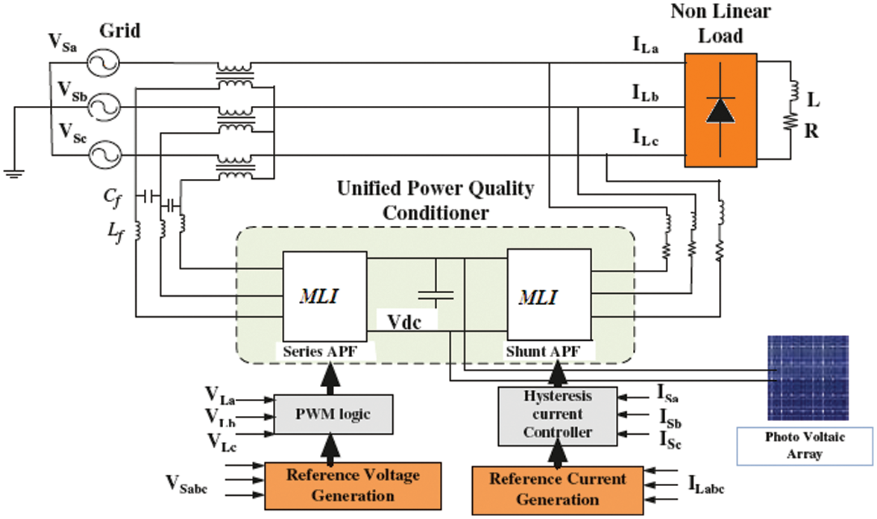
Figure 1: Block diagram of proposed system
3.1 Modelling and Designing of Cascaded Seven-Level Inverter
Multi-level inverters find their familiarity with improved reliability assets on lower switching losses, better voltage, harmonic reduction, and lack of acceptance. The clamping method degrades the inverter, the flying capacitor diode, and the heavy transformer. Then, the Cascade H Bridge MLI has been widely applied in the RES application for a DC source in particular. The Multi-Level Inverter (MLI) measurement of the coming steps depends on the H bridge section’s measurement of the waveform. The multi-Level Inverter does not consistently drop in THD measurements. The staircase waveforms are directed to the yield voltage, displaying the wavelength and switching of harmonics influences. The proposed topology scheme includes three DC sources and five switches for direct and current geographic contrast. It has additional highlights like just two switches leading up to a similar period. Two switches can be used for the ultra-long curves and three-wave switches for the wave generation. The circuit of the proposed seven-level inverter is shown in Fig. 2.
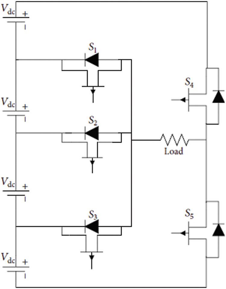
Figure 2: Circuit diagram of Proposed System
The generalized expression for the number of switches and the quantity of dc sources for the proposed topology is given by
where N = number of levels and V = number of switches.
where S = number of dc voltage sources.
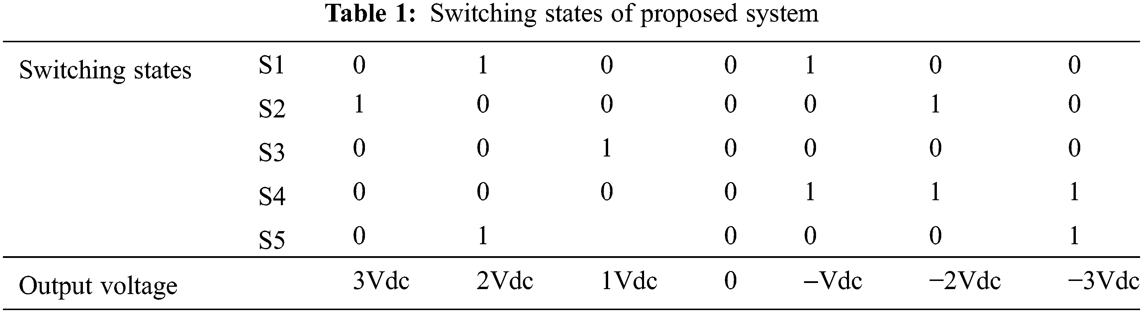
The S4 and S5 switches are utilized for reverse polarity, and the leftover switches are utilized to make levels on both positive and negative to send seven ideal level waveforms. The switching achievement appears in Table 1.
The relationship between current and DC voltage should be examined to create a representation value for CHB. In the ith cell (Si), isolating the AC harmonics voltage (VH1) from the dc voltage across the capacitor of the ith (VI) DC cell reveals the balanced wave.
Find the inverter current and voltage elements from Eqs. (3) and (4). For the liability of multi-level inverter issue, changeability model phasor of inverter action is used in (5)
where
To compile MLI by switching angle h, the bridge step (n) is utilized and MLI is utilized without showing even harmonics (μen = 0). The machine’s current and voltage coordination in each MLI design must be a regulatory gadget for the application to create without displaying even harmonics. With the look at the proposed switching system, the THD relative voltage with a few explicit tuning sales is restricted and doesn’t agree with the consistency of necessities and ideal switching points that are evaluated once. Further, DC voltage coefficients are considered for every harmonic voltage list. As compared with regular strategies, the proposed PWM methodology acquires low THD. The fundamental obligations of the proposed switching framework areas are listed below
i) Start
ii) Elimination of n − 1 harmonic request in an n-level inverter is to be done and closed by THD minimization
iii) Derived THD formula includes n trading edges that lead to more modest inquiry space.
iv) The issue has diverse nonlinear correspondence fundamental to fulfill the change record
v) The ideal exchanging points are evaluated only a single time for all the modification documents.
vi) DC voltage coefficients depend linearly upon the change record and are decided for each M after evaluating exchanging points.
vii) Stop
The Linear predictive Phase Composition can handle various assortment and unconstrained advancements that are not sensible for standard upgrade estimations. Such cases fuse issues in which the objective work is non-differentiable, discontinuous, stochastic, or uncommonly nonlinear. The n-level inverter topology requires (n − 1)/2 (= N) autonomous DC power supplies, where N is the H-bridges quantity.
The size of free voltage sources is 2 V DC/ (n − 1), with the net dc-interface voltage being Vdc. The n-level yield voltage, i.e., −Vdc… −2 Vdc/N, −Vdc/N, 0, +Vdc/N, +2 Vdc/N… + Vdc, can be incorporated using a fitting blend of the switches. The IGBT switches related to the counter equivalent diode are used for high exchanging frequencies. The voltage worry over the IGBT switches is 2Vdc/(n − 1). The switches on the same legare proportional. In this assessment, linear predictive Phase Composition PWM exchanging beat is made and compelled by the proposed Multi-Level inverter’s action. THD can be diminished by controlling the voltage applied to the door terminal of IGBT by using the proposed controller.
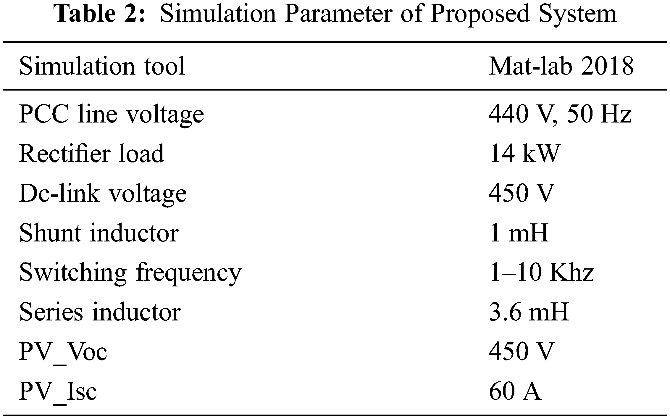
This section discusses the simulation results and performance analysis of the proposed LPPC controller-based UPQC system with a seven-level cascaded h bridge inverter configuration. The Simulink parameter is listed in Table 2.
The proposed PV, with a seven-level inverter-based UPQC system, is shown in Fig. 3. In this work, reference voltage and reference current are generated using the unit vector template method. The Linear Predictive Phase Composition strategy is used to generate the duty cycle for obtaining the MLI output.
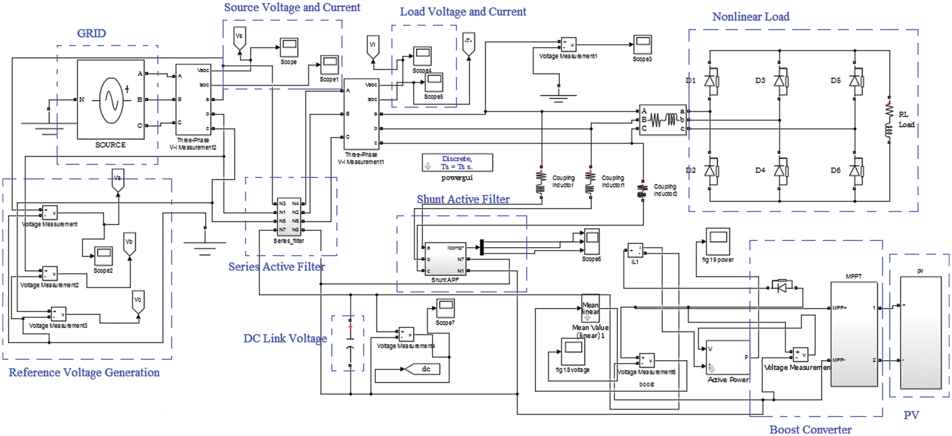
Figure 3: Simulink of proposed UPQC
The simulation result of the solar PV system is shown in Fig. 4. The maximum voltage of PV is 160 V. They perturb and observe method-based MPPT is used to obtain the maximum output voltage of PV.
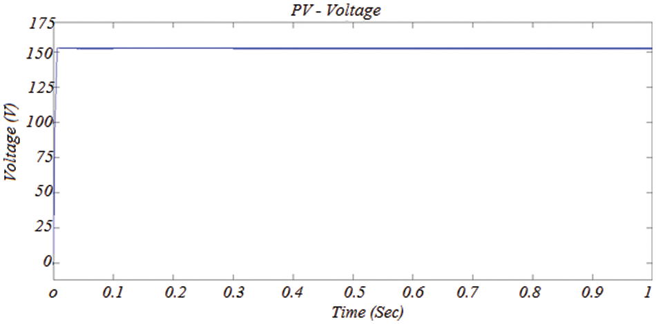
Figure 4: Simulation result of PV
The simulation result of the DC link voltage for the proposed UPQC system is shown in Fig. 5. This DC link voltage is the input for both series and active power inverters. The constant DC link voltage delivers better output, but the unequal DC-link voltage does not give better output. In this research, DC link voltage is maintained constantly at the value of 400 V.
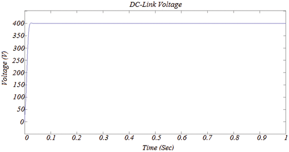
Figure 5: Simulation result of DC-link voltage
The simulation result of the proposed cascaded Multi-Level Inverter is shown in Fig. 6. The duty cycle of MLI is generated using linear predictive phase Composition. The maximum duty cycle’s frequency is 10 kHz, and the simulation output is 440 V.
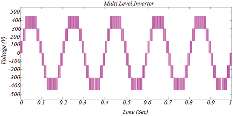
Figure 6: Simulation result of Multi-level inverter
The simulation result of the source voltage is shown in Fig. 7. This voltage has the sag and swells response from 0.2 to 0.5 s and 0.7 to 0.8 s, respectively. This sag and swell response is composted using the proposed MLI-based UPQC configuration.
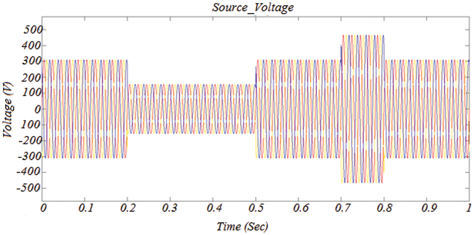
Figure 7: Simulation result of source voltage
The simulation result of the load or compensated voltage is shown in Fig. 8. As compared with source voltage, the proposed UPQC method compensates better for the sag and swell response using an active series filter with the configuration of MLI. The MLI inverter obtains the input voltage from solar.

Figure 8: Simulation result of compensated voltage
The simulation result of the load or compensated current is shown in Fig. 9. As compared with the source current, the proposed UPQC method has a low harmonic response using an active shunt filter with the configuration of MLI. The shunt active MLI inverter obtains the input voltage from solar.
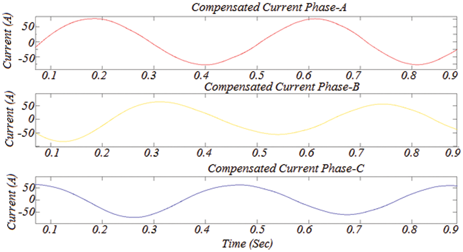
Figure 9: Simulation result of compensated current
The simulation result of Total harmonics Distortion in Load voltage for the proposed solar UPQC system is shown in Fig. 10. This simulation result clearly shows that the proposed system produces the THD less than IEEE standard and the value of load voltage THD is 1.92% concerning 50 Hz frequency.
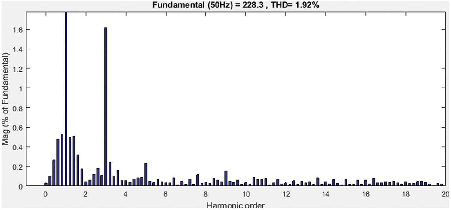
Figure 10: Simulation result of load voltage THD
The simulation result of Total harmonics Distortion in Load current for the proposed solar UPQC system is shown in Fig. 11. This THD simulation result clearly shows that the proposed system obtains the THD below the level of IEEE standard and the value of load voltage THD is 1.26% concerning 50 Hz frequency.
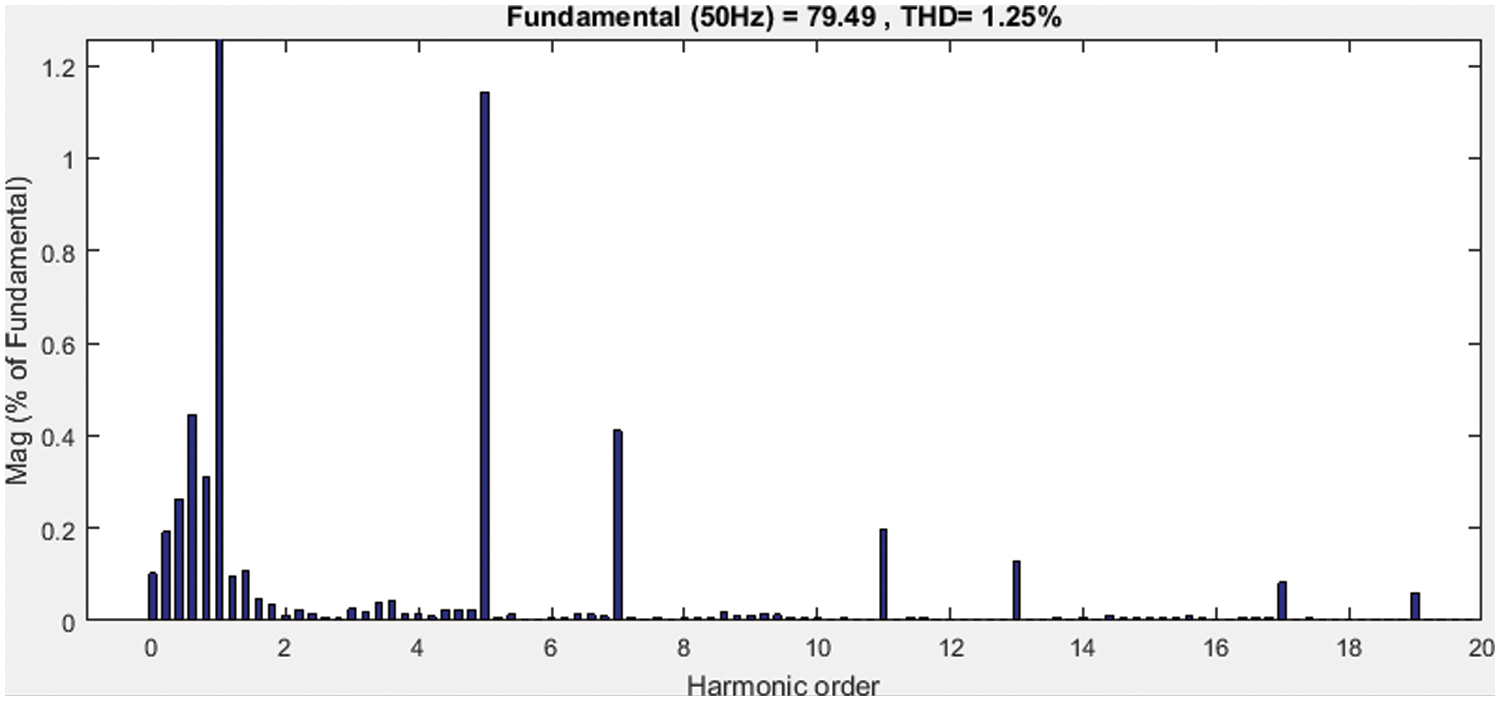
Figure 11: Simulation result of load current THD
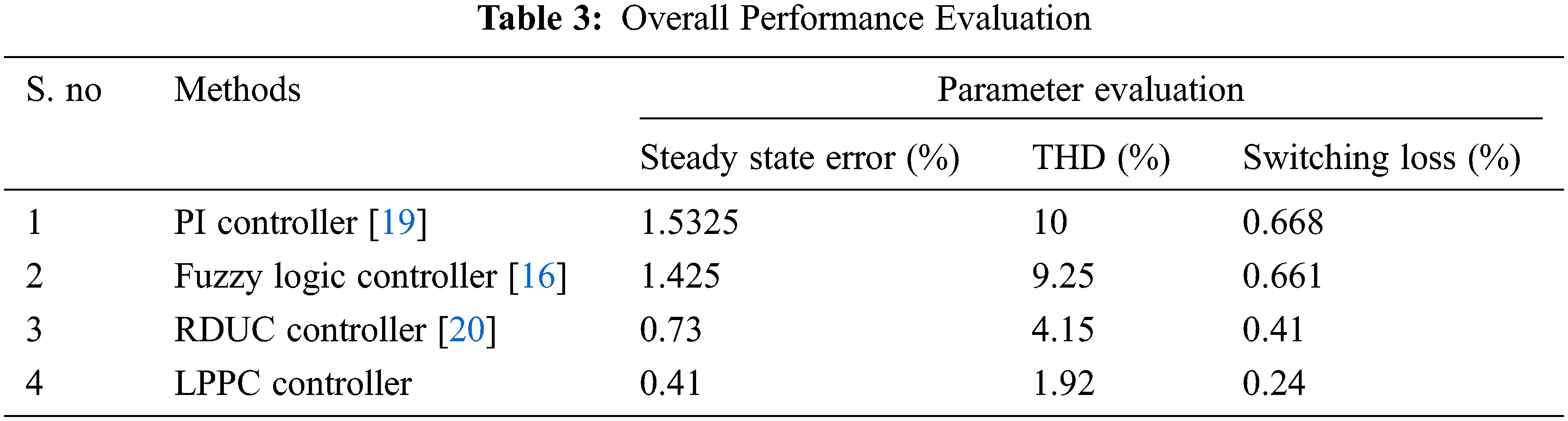
The overall performance Evaluation of the proposed solar-based UPQC with multi-level inverter configuration is shown in Fig. 12 and Table 3. The proposed LPPC method gives the best results than traditional (PI, fuzzy, and RDUC) methods because the proposed method uses a multilevel inverter configuration with a low number of switches then only the performance is improved. For example, the load current THD and load voltage THD of the proposed LPPC-based UPQC system is 1.26% and 1.92% respectively.
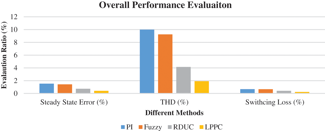
Figure 12: Overall Performance Evaluation
This research describes a new unified power quality conditioning system that is coupled to a solar cell and uses a cascaded multi-level inverter configuration system to compensate for voltage and current disturbances in grid systems at the same time. In this work, the Multi-level inverter model was implemented, and simulation is done on the 11 kv line, and this proposed method decreases the THD value phenomenally. Contrasted with a traditional UPQC, the proposed topology can completely safeguard basic and delicate loads against distortions, sags/swell, and break-in feeder systems. In this research, a7-level inverter UPQC model has been utilized. The presentation of the ML-UPQC is assessed under different unsettling influence conditions and it is demonstrated that the proposed ML-UPQC can compensate sag/swell and interference in compensation. The load current and load voltage THD response of the proposed system are 1.26% and 1.92%, respectively. Soft computing techniques developed can be further used in various fields of power system like–power system dynamics & stability, smart grid, power system state estimation, economic dispatch and optimal power flow.
Funding Statement: The authors received no specific funding for this study.
Conflicts of Interest: The authors declare that they have no conflicts of interest to report regarding the present study.
References
1. D. De Yong, S. Bhowmik and F. Magnago, “Optimized complex power quality classifier using one vs. rest support vector machines,” Energy Power Eng, vol. 9, no. 10, pp. 568–587, 2017. [Google Scholar]
2. A. Javadi, A. Hamadi, L. Woodward and K. Al-Haddad “Experimental investigation on a hybrid series active power compensator to improve typical households power quality,” IEEE Transaction on Industrial Electronics, vol. 63, no. 8, pp. 4849–4859, 2016. [Google Scholar]
3. A. Javadi, L. Woodward and K. Al-Haddad, “Real-time implementation of a three-phase THSeAF based on a VSC and a P+R controller to improve the power quality of weak distribution systems,” IEEE Transaction on Power Electronics, vol. 33, no. 3, pp. 2073–2082, 2018. [Google Scholar]
4. M. A. Mansor, M. M. Othman, I. Musirin and S. Z. M. Noor, “Dynamic Voltage Restorer (DVR) in a complex voltage disturbance compensation,” Int. J. Power Electronics and Electron. Drive Systems, Syst., vol. 10, no. 4, pp. 2222–2230, 2019. [Google Scholar]
5. C. Kumar and M. K. Mishra, “Operation and control of an improved performance interactive DSTATCOM,” IEEE Transaction on Industrial Electronics, vol. 62, no. 10, pp. 6024–6034, 2015. [Google Scholar]
6. Y. Hoon, M. M. Radzi, M. Hassan and N. Mailah, “Control algorithms of shunt active power filter for harmonics mitigation: A review,” Energies, vol. 10, no. 12, pp. 1–29, 2017. [Google Scholar]
7. L. B. Garcia Campanhol, S. A. Oliveira da Silva and A. Goedtel, “Application of shunt active power filter for harmonic reduction and reactive power compensation in three-phase four-wire systems,” IET Power Electronics, vol. 7, no. 11, pp. 2825–2836, 2014. [Google Scholar]
8. Y. Hoon, M. A. M. Radzi, M. K. Hassan and N. F. Mailah, “Operation of three-level inverter-based shunt active power filter under non-ideal grid voltage conditions with dual fundamental component extraction,” IEEE Transaction on Power Electronics, vol. 33, no. 9, pp. 7558–7570, 2018. [Google Scholar]
9. E. Hossain, M. R. Tur, S. Padmanaban, S. Ay and I. Khan, “Analysis and mitigation of power quality issues in distributed generation systems using custom power devices,” IEEE Access, vol. 6, pp. 16816–16833, 2018. [Google Scholar]
10. K. Hasan, M. M. Othman, N. F. A. Rahman, M. A. Hannan and I. Musirin, “Significant implication of unified power quality conditioner in power quality problems mitigation,” International Journal of Power Electronics and Drive System, vol. 10, no. 4, pp. 2231–2237, 2019. [Google Scholar]
11. C. K. Sundarabalan, Y. Puttagunta and V. Vignesh, “Fuel cell integrated unified power quality conditioner for voltage and current reparation in four-wire distribution grid,” IET Smart Grid, vol. 2, no. 1, pp. 60–68, 2019. [Google Scholar]
12. S. Devassy and B. Singh, “Design and performance analysis of three phase solar PV integrated UPQC,” IEEE Transaction on Industry Application, vol. 54, no. 1, pp. 73–81, 2018. [Google Scholar]
13. L. B. G. Campanhol, S. A. O. da. Silva, A. A. de. Oliveira and V. D. Bacon, “Power flow and stability analyses of a multifunctional distributed generation system integrating a photovoltaic system with unified power quality conditioner,” IEEE Transaction on Power Electronics, vol. 34, no. 7, pp. 6241–6256, 2019. [Google Scholar]
14. A. M. Gee, F. Robinson and W. Yuan, “A superconducting magnetic energy storage-emulator/battery supported dynamic voltage restorer,” IEEE Trans. Energy Convers, vol. 32, no. 1, pp. 55–64, 2017. [Google Scholar]
15. W. U. Tareen and S. Mekhilef, “Transformer-less 3p3w SAPF (three phase three-wire shunt active power filter) with line-interactive UPS (uninterruptible power supply) and battery energy storage stage,” Energy, vol. 109, pp. 525–536, 2016. [Google Scholar]
16. H. Kenjrawy, C. Makdisie, I. Houssamo and N. Mohammed, “New modulation technique in smart grid interfaced multilevel UPQC-PV controlled via fuzzy logic controller,” Electronics, vol. 11, no. 6, pp. 919, 2022. [Google Scholar]
17. J. Han, X. Li, Y. Sun, S. Gong and S. Huang, “Quadruple-active-bridge based unified power quality conditioner-L with fault current limiting capability,” Electric Power Systems Research, vol. 206, pp. 107780, 2022. [Google Scholar]
18. M. Amini and A. Jalilian, “A new operational approach to minimize open unified power quality conditioner rating: OUPQC-V Amin,” Electric Power Systems Research, vol. 203, pp. 107648, 2022. [Google Scholar]
19. S. Lakshmi Kanthan Bharathi and S. Selvaperumal, “MGWO-PI controller for enhanced power flow compensation using unified power quality conditioner in wind turbine squirrel cage induction generator,” Microprocessors and Microsystems, vol. 76, no. 0141–9331, 2020. [Google Scholar]
20. S. K. Abdul Pasha1 and N. Prema Kumar, “Model Predictive Controller based Unified Power Quality Conditioner for Voltage Regulation Studies in 33-Bus Closed Loop Distribution System,” E3S Web of Conferences, pp. 1–6, 2020. [Google Scholar]
Cite This Article
 Copyright © 2023 The Author(s). Published by Tech Science Press.
This work is licensed under a Creative Commons Attribution 4.0 International License , which permits unrestricted use, distribution, and reproduction in any medium, provided the original work is properly cited.
 Downloads
 Citation Tools