
 Submit a Paper
 Propose a Special lssue
 Open Access
ARTICLE

Real-Time Indoor Path Planning Using Object Detection for Autonomous Flying Robots
National Defence University, Hezârfen Aeronautics and Space Technologies Institute, Istanbul, 34039, Turkiye
* Corresponding Author: Onder Alparslan. Email:
Intelligent Automation & Soft Computing 2023, 36(3), 3355-3370. https://doi.org/10.32604/iasc.2023.035689
Received 31 August 2022; Accepted 14 November 2022; Issue published 15 March 2023
 View Full Text
 Download PDF
Abstract
Unknown closed spaces are a big challenge for the navigation of robots since there are no global and pre-defined positioning options in the area. One of the simplest and most efficient algorithms, the artificial potential field algorithm (APF), may provide real-time navigation in those places but fall into local minimum in some cases. To overcome this problem and to present alternative escape routes for a robot, possible crossing points in buildings may be detected by using object detection and included in the path planning algorithm. This study utilized a proposed sensor fusion method and an improved object classification method for detecting windows, doors, and stairs in buildings and these objects were classified as valid or invalid for the path planning algorithm. The performance of the approach was evaluated in a simulated environment with a quadrotor that was equipped with camera and laser imaging detection and ranging (LIDAR) sensors to navigate through an unknown closed space and reach a desired goal point. Inclusion of crossing points allows the robot to escape from areas where it is congested. The navigation of the robot has been tested in different scenarios based on the proposed path planning algorithm and compared with other improved APF methods. The results showed that the improved APF methods and the methods reinforced with other path planning algorithms were similar in performance with the proposed method for the same goals in the same room. For the goals outside the current room, traditional APF methods were quite unsuccessful in reaching the goals. Even though improved methods were able to reach some outside targets, the proposed method gave approximately 17% better results than the most successful example in achieving targets outside the current room. The proposed method can also work in real-time to discover a building and navigate between rooms.Keywords
Robots are widely used by humans to facilitate their daily lives. Apart from diverse daily life benefits, many special tasks are designed to be carried out by robots, especially if it is not possible for humans to fulfil those tasks due to personal difficulties or high risks to people. For example, explosive ordnance disposal (EOD) robots are used for the disposal of bombs and unknown objects, as these objects can cost the lives of EOD staff. Likewise, robots can be used efficiently by emergency and rescue teams to act in hazardous situations. In the buildings that are at risk of collapse, or in case it is difficult to reach farther rooms, robots with a small size and resilient movement capability can discover surroundings and detect potential targets for rescue teams. Additionally, it is important to understand the plan of the building and what is inside before rescue teams go inside. For example, in order to find an exact room such as a kitchen, a search robot may use classifying information of the surrounding objects and determine the room by learning the common features of the kitchen.
A robot can also detect living things (humans and animals) and materials that may be injured (kitchen tubes, flaming materials, etc.) in the building. This information provides the rescue team with a better understanding of the unknown environment and provides options to take necessary measures against possible harm.
The navigation of robots inside buildings is in different formats due to the requirements. Search robots are sometimes in a snake-like shape in order to curl between narrow spaces [1], have jumping skills [2], or have flying capabilities like quadrotors [3]. These different capabilities enable robots to enter places that are almost impossible to be reached by humans. In damaged buildings, items in the room may fall, and there can be stairs, water, or debris on the floor which may cause an obstruction to ground vehicles trying to traverse the area. On the other hand, rotary-wing flying robots like multicopters may move more effectively through a building by utilizing a 3-axis movement. They can easily fly over materials such as furniture and pass-through gaps, which are sufficiently wide enough to allow the transition of the multi-copter. Rescue teams can benefit from the aerial wide-angle view of flying robot’s cameras to have an informed picture of the location. Even if they have various limitations, multicopters can be preferred for use in hazardous buildings instead of ground vehicles to discover the place, detect desired objects inside, and carry out other duties within their limits.
Despite having many advantages, one of the most considerable constraints of flying robots is their limited payloads. Even though many novel methods need more computational power, the smaller mobile devices may meet the power requirements adequately with the latest developments in graphic processors. The presence of graphics processing units (GPU)-accelerated parallel processing units in mobile embedded systems provides more resilience for complex calculations, especially in real-time applications [4]. Owing to the rapid developments in detection and classification algorithms, it has become possible to detect and classify objects in real-time with limited computing power [5,6].
To employ an autonomous flying robot, which aims to help rescue teams by detecting people, valuable objects, and mapping an unfamiliar location, the robot needs to have a real-time path planning method and object detection algorithm. The real-time information, including the class of the objects and position, can be used in the path planning algorithm to state hazardous positions and crossing points to go out of the room. The robot constantly updates its trajectory by detecting these key points and locating their position on the robot’s path plan, while concurrently collecting valuable information for the rescue team. If the destination of the robot is obscured in a search, the crossing points of a building, such as windows, stairs, and doors may then be employed as temporary targets for the robot to travel to another room or escape from an area. If the robot has an opening mechanism, these crossing points can be used even if they are closed. In some cases, the desired goal point of a robot cannot be achieved because of the inaccessibility or local minima problem of the path planning method. Therefore, being aware of crossing points will likely help the robot by directing itself to these crossing points before reaching the final target.
The main objective of this study is to elaborate on the perception of the environment by object classification and leverage that information for the path planning of an autonomous mobile robot. This will help the robot to easily traverse a building or escape the area, tolerate congestion of the path planning algorithm, and determine the periphery of the robot. For these purposes, an object detection reinforced artificial potential field (APF) algorithm is proposed to be used in autonomous air vehicles in unknown environments such as damaged buildings. The main contributions of the study are the development of an object detection algorithm to determine the feasibility of a detected crossing point for the quadrotor and through an APF method, to be best adapted to indoor environments by providing escape when a robot is congested. A novel fusion method for camera and LIDAR sensors is also proposed to precisely locate positions, distances, and lengths of detected objects. In Section 2, related works are presented. In Section 3, the method for combining sensory data is explained and the detection of crossing points is introduced. The proposed path planning method is presented in Section 4. The system simulation and test results regarding the robot’s autonomous trajectory in an unknown place are provided in Section 5 together with the evaluation of the results. Finally, in the conclusion, the study is summarized and potential future works are recommended.
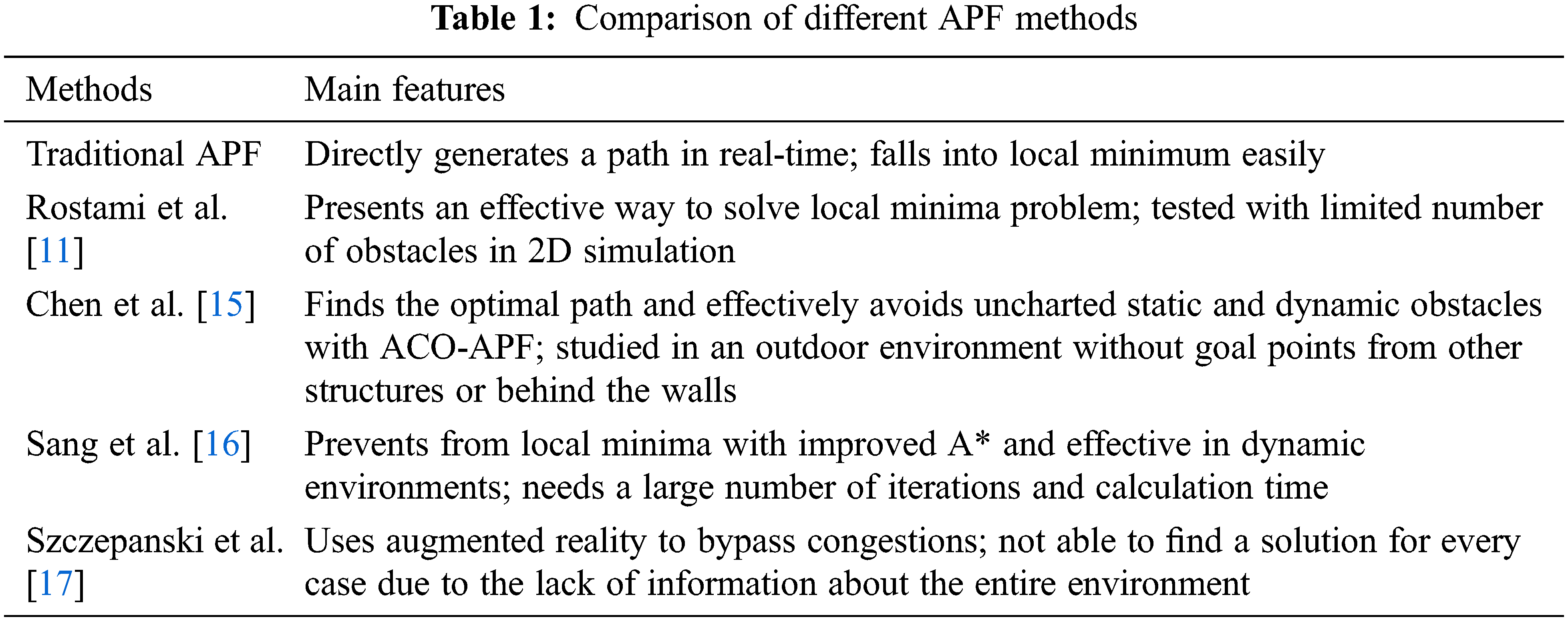
There are many models that have been used to find a secure and short path for autonomous robots. The success of the methods varies due to the circumstances of the environment, computation time, and the processing device. Challenging conditions such as unknown indoor environments, limited payloads of flying robots, and the need for real-time operations require a robust but simple planning algorithm. Gopikrishnan et al. investigated path finding algorithms and compared the cost and error rates of four different algorithms [7]. They concluded that Potential Fields method is better despite its disadvantages, which include being less accurate in congested areas and having the potential to go into local minimum. Scheggi and Misra compared six path planning algorithms for the navigation of micro-sized objects and stated that although there is no big difference among the methods regarding the accuracy, A* with quadtrees and APF are best suited for computation performance [8]. Katiyar and Dutta obtained comprehensive path planning comparisons among a modified APF method, sampling-based technique (RRT*), and particle swarm optimization (PSO) algorithm [9]. They concluded that sampling-based and APF-based techniques took approximately one fifth of the time. Yan et al. planned the path of a robot in a static environment [10]. They proposed an improved APF method to overcome the problems of the classical potential field algorithm and claimed that the robot reached its target by avoiding the local minima trap. Rostami et al. proposed a modified APF algorithm to solve the local minima problem [11]. The main difficulties associated with the original potential field method [12] were determined to be responsive forces of the obstacles close to the target and caused the vehicle to halt when avoiding the obstacles [13]. These drawbacks were overcome, and the proposed method was retested on a quadrotor. Cetin et al. leveraged APF for a flight of a formation of unmanned air vehicles [14]. They benefited from sigmoid functions instead of binary limiting functions to determine the limits of potential fields, which were more effective and functional robot manoeuvres were provided for several robots to avoid obstacles and each other. However, depending on the position of the target point of the robot, all these methods fell into the local minimum in some cases. As a result, it was determined that the APF method could be assisted with other methods. Chen et al. used APF with Ant Colony Optimization [15], Sang et al. integrated APF with the A* algorithm [16] and Szczepanski et al. supported APF with augmented reality [17]. Comparisons of these methods, their advantages and disadvantages are given in Table 1. These improvements may help the robot to reach its target without being stuck for some goal positions. However, if the robot falls into local minimum with just one of these algorithms, then there is no solution to free the robot from that point. On the other side, determining that the crossing points of a closed space to go into a hallway, another room or outside and setting them as temporary target points can redirect the robot and save it from the local minimum.
In a building, possible objects to allow the robot to move into another space are doors, windows, and stairs. To be able to detect and classify doors, convolutional neural networks (CNN) [18] and depth information [19] are studied by various researchers. Another study benefited from point clouds to detect open doors and clearance on walls [20]. More progress was made on classifying semi-open doors [21]. Kwak et al. were able to transport the robot into another room by classifying the doors and their handles in an office environment [22]. The success of the detection of indoor crossing points in related literature encourages us to benefit from it in our study.
Current object detection methods may classify indoor objects very accurately. On the other hand, the need for large computing power for object detection methods limits their usage for UAVs that have limited payload capacities. One-stage detection models are a more reasonable option for UAVs when considering this constraint. Even though they are less accurately able to detect small-sized objects, real-time working strategy forces us to utilize them. YOLOv4 was claimed as the fastest detection algorithm in Bochkovskiy et al.’s study [23] and it was employed in this study as it is the optimal detection algorithm compared to its peers. Although possible crossing points can be detected and classified with this algorithm, they also need to be tagged as open/closed and wide/narrow simultaneously in order to understand whether they can be included in the navigation plan. Rendering this entire process should be quite simple since the robot can only have limited computational power.
In addition to detecting an object with optical data, its width and distance need to be measured with a metric sensor to have a better understanding of this object. Since the classical APF method benefits from LIDAR sensors to determine the path plan, the best option may be to fuse it with the optical sensor. For the fusion of sensors, computer vision techniques have been employed in several studies [24]. These methods can be adapted to the fusion of different sensors. In this study, 2D LIDAR usage is planned, though the 3D LIDARs have a wider view of the environment. The current 3D LIDAR sensors have some disadvantages due to the structural aspects such as the rotation frequency, the signal processing bottleneck [25], and because it is more expensive. Because UAVs have limited payload capacity, and this issue is afforded the highest priority in the work, a lightweight sensor is therefore considered sufficient to satisfy the needs of the robot to locate targets and obstacles. Moreover, we intended for the study to experience the performance of 2D LIDAR on UAVs, which have 6DOF movement competence. By using a multirotor, it is easy to change altitude on the z-axis and scan the environment at different heights. Even though more detailed information can be obtained using 3D LIDAR, the 2D LIDAR data is calculated faster, easier to calibrate with an optical sensor and sufficient enough for the requirements of this study.
A review of the object detection and path planning methods showed that it was possible to use path planning and object detection algorithms concurrently in a small-sized flying robot. After analyzing the algorithms, the APF method was utilized for the path planning algorithm since it is relatively simple, has a lower computational cost compared to other path planning algorithms and is generally compatible with unmanned aerial vehicles (UAV). On the other side, YOLOv4 is preferred as the detection algorithm as it is quite fast and sufficiently accurate.
3 Sensor Fusion and Detection of Crossing Points
Sensor perception comprises of the acquisition and processing of data collected by sensors in order to create a model representing the environment. One of the research interests in robotics is using different sensor data together to have a better understanding of the environment by taking advantage of various features simultaneously. Robots can adapt to surroundings more easily in varying conditions with the help of different perceptions such as light, heat, color, sound, etc. It may also make more precise decisions if it can combine data taken from diverse number of sensors. Also, multiple sensors can be employed for inner comparison to improve data accuracy or to strengthen weaker information. Likewise, determining the category of the objects in their surroundings with an optical sensor and computing their distance with the fusion of sensors is an effective way for the safe travel of the robots when these objects are included in the path plan. In this study, a novel method is used to determine whether a crossing point meets the parameters to pass through by registering the LIDAR and optical sensor data as seen on the flowchart of the algorithm (Fig. 1). For this purpose, an object detection method is improved upon in order to categorize usable structural objects and a fusion method is then proposed.
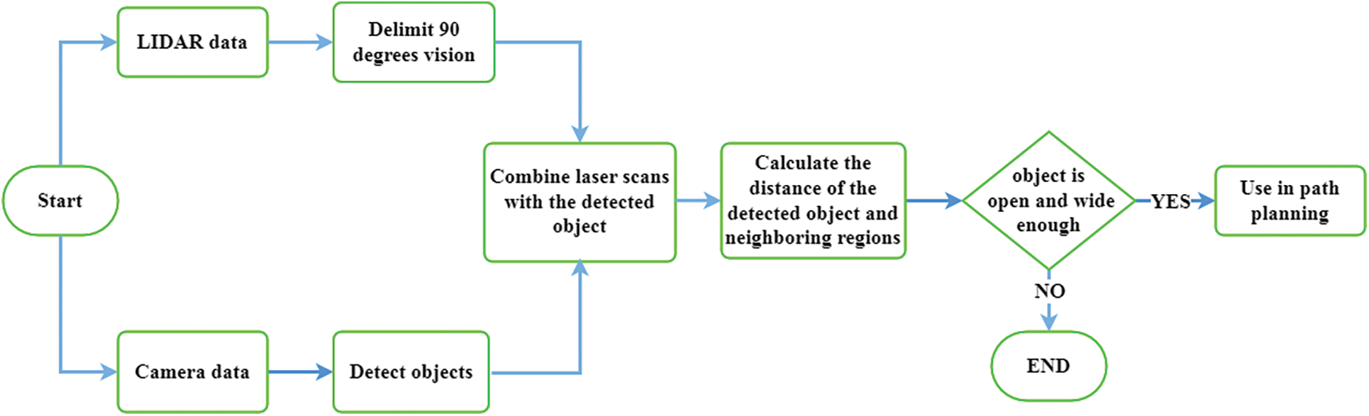
Figure 1: The flowchart of the methodology used for registering the sensor data and determining whether a detected object is valid to use for UAV’s navigation
To be able to use different sensor data for the same purpose, there should be an alignment among them. Considering a UAV already has sensors to carry out tasks such as monitoring and mapping for search and rescue teams, the fusion is planned with those sensors already present. Data acquired from optic and LIDAR sensors may be used for several purposes at the same time for SLAM, obstacle avoidance, and path planning. In this study, an ordinary optical camera and LIDAR sensor are employed and they are put under one another.
In order to provide a robust alignment, a setup has been prepared to comprise one flat black background and two green rectangle boxes. In this setup (Fig. 2), green boxes are detected, and their center points are determined with a simple computer vision method of the optical data. A LIDAR sensor can also recognize these green boxes because they are the only objects in the area. Once both sensors are aware of the positions of the boxes, sensors can then be aligned and calibrated. The distance between the detected calibration points (centers of the boxes) is measured in pixel values, LIDAR beam angles, and metric values. The positions of the boxes are displaced twice, and the measurements are taken again. By considering these values for the three different box displacements, sensors are acutely aligned to detect the same position with a simple comparison of the changes to the proportion of sizes of the recaptured images.
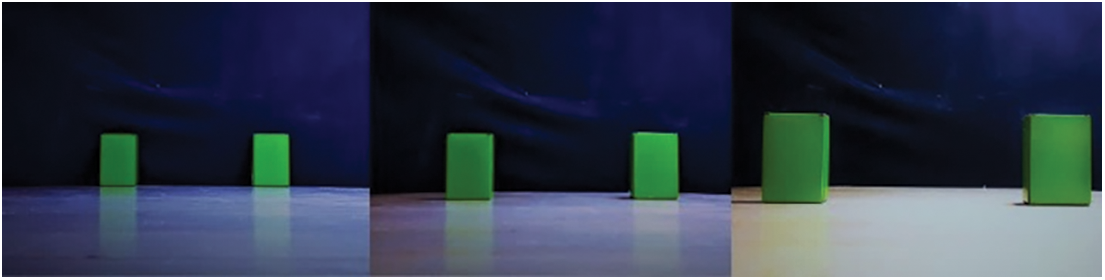
Figure 2: The setup for sensor alignment
In order to classify objects in the range of the camera, a full HD optic camera is employed. On the other side, the limited view of the camera (90 degrees) means that it is not possible to utilize each laser scan and the relevant laser beams are required to be extracted. Even if it is not likely to keep the LIDAR from turning 360 degrees, it is probable to eliminate scan data which is unusable for fusion. The scans belonging to the corresponding part with a 1920 × 1080 camera view are delimited as in Fig. 3 and saved to the distance metrics list by using Eq. (1) where rα is the distance of the sensor for angle α.
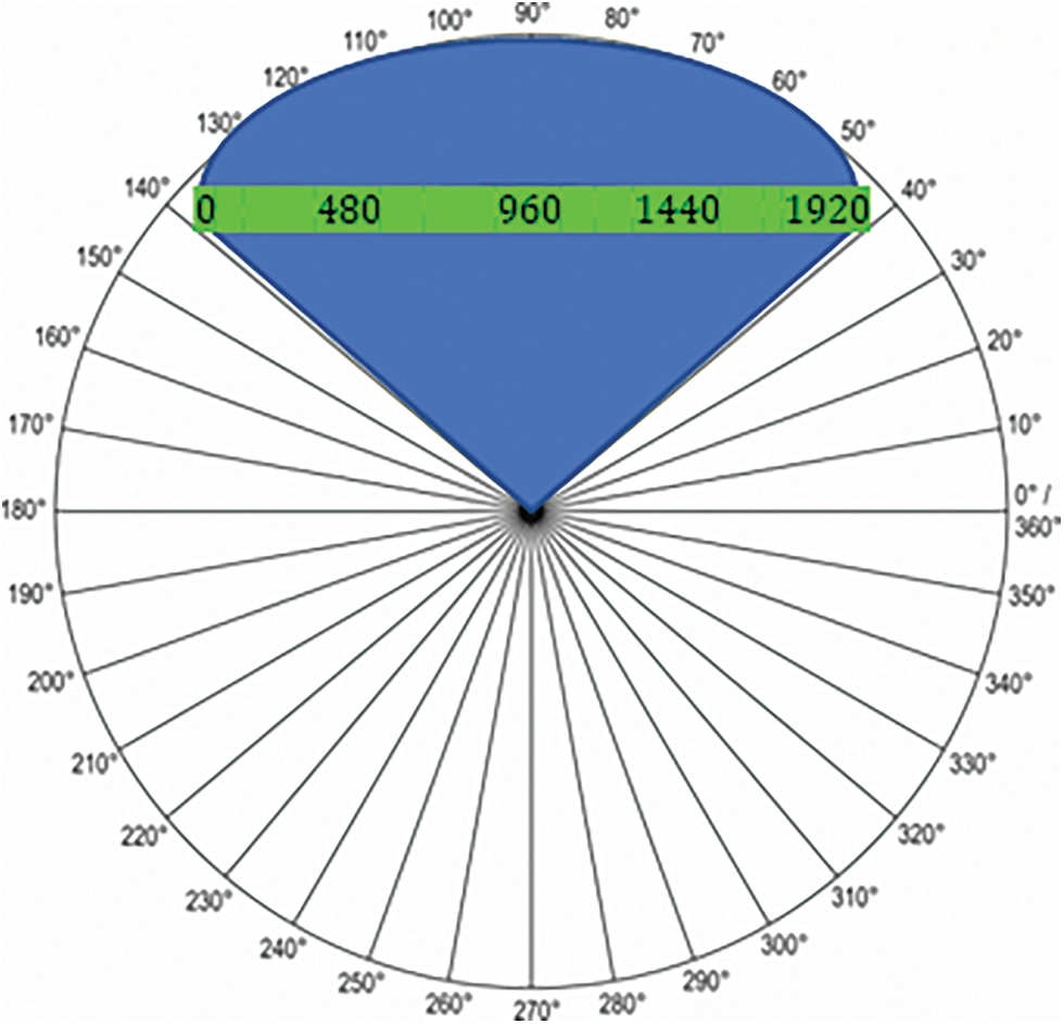
Figure 3: Combining a 360 degree view of LIDAR with a 1920 * 1080 pixel camera
3.2 Detection of Suitable Crossing Points
The decision process starts with the acquisition of LIDAR and camera data. The classification algorithm detects indoor objects and determines their position on the image by pixel values. On the other hand, laser scans are restricted to the 90-degrees vision and the corresponding image pixel values are calculated. After these operations, it is possible to find laser scans hitting the detected object. Subsequently, the distance between the detected object and its neighboring regions can be calculated through these scans, making it possible to determine whether the object is open or not. Finally, the width of the crossing point is calculated via metric values. Thus, the detected object can be used in the path planning algorithm as a gateway if it is open wide enough. Once an object is detected, its position on the image is saved as per Eq. (2) where xi and yi are the starting pixel values, wi and hi are the width and height values of an object i.
Bounding box values of a detected object are also recorded in the list βi to be able to use related laser scans. βi has the values of the horizontal position of the object divided by iw/90, where iw is the width of the camera image in pixel values. The detection algorithm may classify n number of objects in an image which leads to saving n number of list βi. With the list in Eq. (3), we saved the detected object’s position by LIDAR angle values corresponding to pixel values. To obtain the distance of the related object, distance values of list βi are then assigned to list Ri as in Eq. (4).
By registering LIDAR data with the optical image, it is possible to figure out whether the detected object is open or closed in addition to calculating its distance. With the above equations, LIDAR beams hitting the detected object are determined and the average distance of it is obtained by laser distance values. Likewise, the left and right parts of a detected object can be determined, and their distance values measured by LIDAR data. These right and left regions are defined by advancing from the actual object as much as half of its width to both directions as shown in Fig. 4. We captured LIDAR beams belonging to the left and right parts into two lists as in Eqs. (5) and (6).
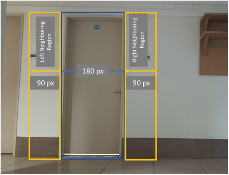
Figure 4: Constructing of neighboring regions according to a detected object’s width
The average distance of the detected object and its neighboring parts are then calculated by using Eq. (7) and these three values are compared to each other as per Eq. (8). In the case where an object is open, its right or left part should be closer to the robot. Nevertheless, this distance value might be misleading for various reasons.
Most of the doors and windows have sills which create a difference in distance value between the wall and the crossing point. Those sills are usually between 0, 2 m to 0, 3 m in length. Moreover, a slightly open door can cause more distance differences between these regions. To provide the quadrotor a safe passage, there needs to be more than 0, 9 m of space. For these reasons, the distance difference between the regions needs to be bigger than 0, 9 m. This threshold value can be easily configured according to the quadrotor’s frame length.
Lastly, for the classification of crossing points, it is checked whether a door or window is wide enough to let the UAV go through. An object’s width is found by using its width in pixel values, distance in metrics and the camera’s view angle. A coefficient value is discovered by measuring the width of the whole image where the camera is at a fixed distance. Since the captured image (1920 pixels) means 1.8x from x meter distance according to this measurement, the width of an object is calculated by using Eq. (9), where wr is the number of pixels occupied by the object on the image in pixels, do is the distance of the object in meters, wi image width in pixels and k is coefficient value.
This section explains the path planning algorithm of a UAV in an unknown environment using LIDAR and camera sensors. For the navigation of the robot to reach a goal point, many path planning algorithms in the literature can be used. The modified object classification method in this study can work with different path planning algorithms. However, APF-based path planning has been chosen within the scope of the study. Contrary to classical APF methods, information about detected suitable gateways is added, which provides many advantages. Even if the robot gets stuck to local minimum, a possible gateway like a door or windows can be determined as temporary goal and the robot may be able to get out of the position.
The APF method is a frequently used technique for autonomous mobile robots to avoid obstacles and navigate to the desired destination [14]. The basic concept of the potential field method is to define forces to create a path plan. The target of the robot creates an attractive vector to draw the robot to the target and the obstacles around the robot then create repulsive vectors to keep the robot away. The robot moves in the direction of the combination of these repulsive and attractive vectors. To mitigate the possible local minima problem, harmonic functions were used in Kim and Khosla’s study [26]. The repulsive and attractive forces are calculated as logarithmic functions and they are modified as in Eqs. (10) and (11). The attractive force is found by using λ and k coefficients and the Euclidean distance of the quadrotor (qx, qy) to the goal coordinates (gx, gy). This provides an increase in the force until a maximum value by which an attractive force is bounded while the robot is getting farther from the target. Also, a threshold value is employed for the navigation of the robot into narrow spaces. When the robot gets closer than dt distance to the goal (dg), the attractive force is not being reduced anymore in order to prevent the repelling effects of the near obstacles. On the other side, another coefficient σ is used for determining the repulsive force. Contrary to the attractive force, the repulsive force gets bigger as the robot gets closer to the obstacle. The repulsive force for point (px, py) is 0 if the distance value (dp) is bigger than 1.22 meters (dmin). These threshold values are found after a great number of tests to transport the quadrotor safely in closed spaces. Lastly, when the robot is close enough to the target, the attractive and repulsive forces are reset to finalize the task and keep the robot away from oscillations.
The resultant force affecting the robot is formed by regarding the distance values of attractive and repulsive forces. It is obtained by using Eq. (12) which determines the path of the robot to reach its goal. However, in each step, it needs to be calculated according to the movement of the mobile robot.
Fig. 5 shows a sum of the forces exemplifying a place consisting of seven repulsive forces and a single attractive force and the route of a robot with APF method. The goal which the robot aims to arrive at is the focal point of the attractive field and the obstacles which the robot aims to avoid while moving forward to the ultimate point, are the center points of the repulsive fields in the same coordinated system. Having a resultant force for any time, the robot can go towards the target as soon as it is detected.
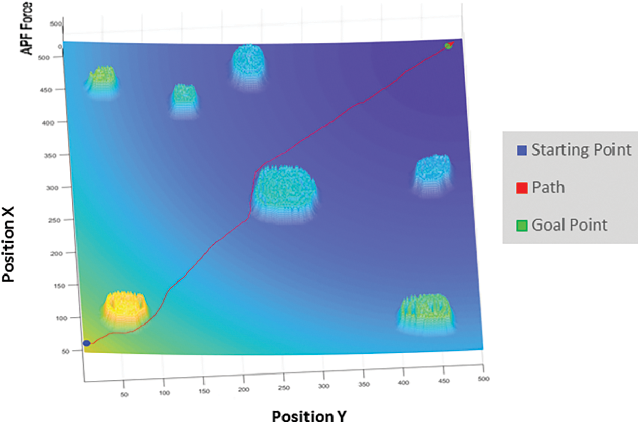
Figure 5: Finding a secure path to a target point with APF
In navigation tasks, the robot may use crossing points (door, window, stairs) for three purposes. One is the lack of a final target. If the robot is trying to discover a building and needs to go from one room to another or different floors, it can determine the detected objects as goal points for the path planning algorithm. Another aim is the local minima problems of navigation methods. Kim and Khosla define the structural local minimum as “a static equilibrium where the robot cannot move any more with a current artificial potential” [26]. Even if there is a path from the starting point to the target point, it might not be calculable by the robot, or it may get stuck in a particular position. In those cases, the robot can use the crossing points to escape its position and find a new path to the final target. In another case, goal points might be unusable if the crossing points are closed. In those cases, the robot can go to the crossing point and open the door/window with an opening mechanism. However, this last case is not addressed as working with the robot arm is another study field.
Considering the motivation of the study, the general flowchart of the proposed path planning method is shown in Fig. 6. If the robot undertakes a discovery duty, then it will map the room while the object detection algorithm classifies all of those objects it finds. When the mapping is completed, it will then search for a crossing point to enter another room. The detected objects (doors and windows) are utilized in the path planning algorithm as temporary targets if they are classified as open, large enough, and unvisited. After reaching the temporary target, the robot controls its own task and continues to discover the building room-by-room. The location of the temporary target is calculated using the robot’s current position, the relative position of the target, and the distance of the target to the robot. Considering the quadrotor’s heading (α) and the object’s angle to the quadrotor’s heading (θ), we can find the object’s position through Eq. (13) where oix and oiy are the coordinates of the detected object, qx and qy are the quadrotor’s coordinates, and Di is the distance between the detected object and the robot.
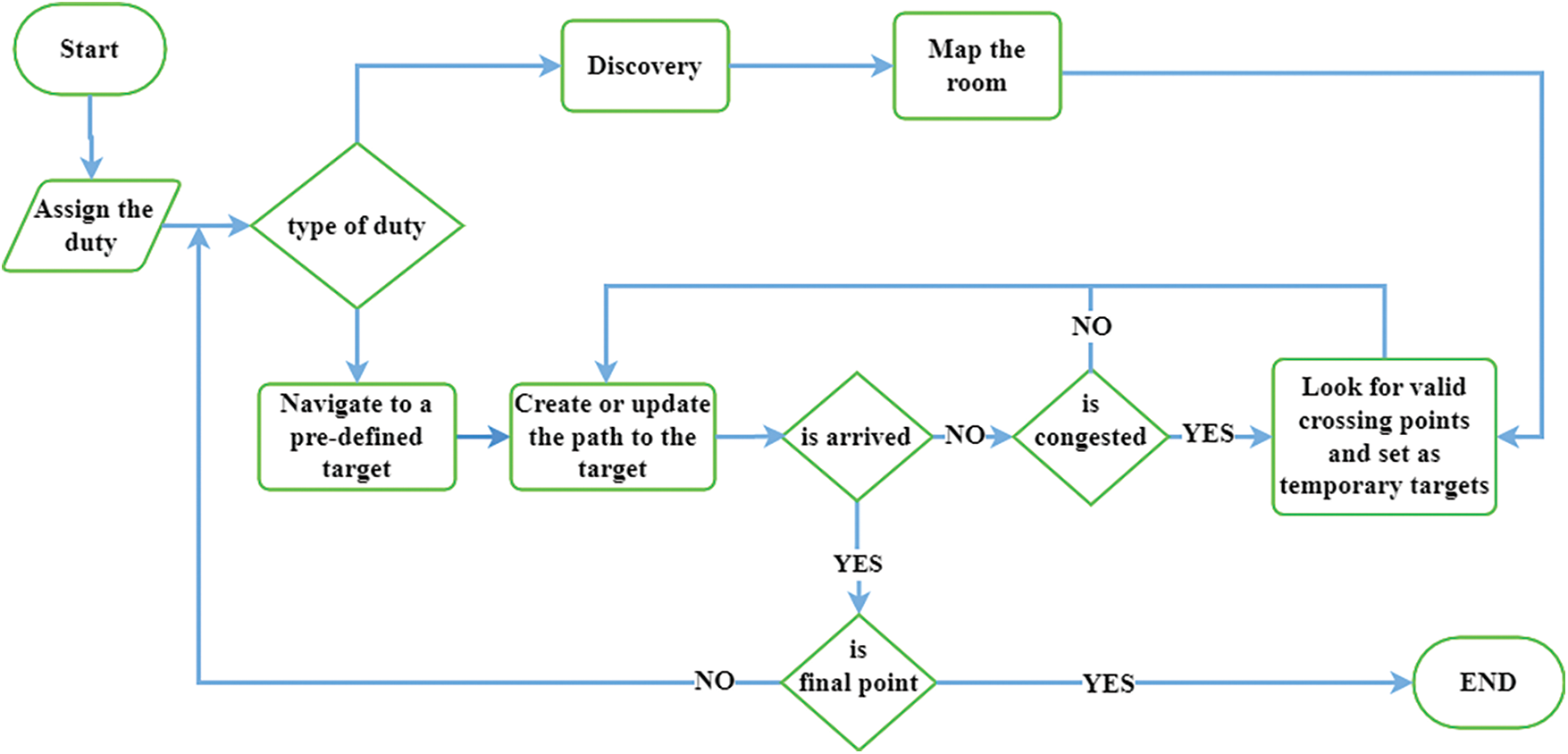
Figure 6: Flowchart of the proposed path planning method
In the case where a goal point is given to the robot, it navigates to this point with the proposed path planning algorithm. Whenever the robot gets stuck in a position, it defines it as a temporary target and twists to the possible crossing point’s position. Subsequently, the robot then proceeds to the target and uses the resultant force data to avoid obstacles and go around them as in Fig. 5. The location of the target and the best way to reach it are continuously updated. Once the robot arrives at its temporary target, it then starts to look for a path to the final target or search for a new gateway.
In this section, dataset, simulation environments and sample scenarios are presented and the results of the suggested approach are discussed. The success of the dataset and the usage of the classification information in navigation are tested in a simulated environment.
Several online datasets are available for use to detect windows, doors, and stairs. However, in order to classify objects successfully in disaster zones, more effort is needed due to damaged objects, possibly overlapping and partial views and different light conditions. In this study, original images, images taken from online sources as well as images from OpenImages [27], DoorDetect [28], and Stairs Detection [29] datasets are used. To enhance the dataset’s accuracy, data augmentation methods are conducted. By flipping, rotating, cropping, and scaling the images, it is projected that the robot will detect partial and different sized objects, even when viewed from different angles. A total of 5042 images are acquired as part of the process to identify those crossing points (3140 doors, 1584 stairs and 9312 windows) and the images are annotated with a Yolo Annotation Tool. This dataset can be viewed at https://www.kaggle.com/datasets/nderalparslan/dwsonder. It is randomly divided into two pieces and 90% of the images are used for training, while 10% for testing. For the purposes of the training process, we identify the batch size as 48, epoch 378, learning rate 0.001 and an image size of 416 × 416. The training set is then trained for 15000 iterations. For the process to have a better understanding of the test results, a 5-fold cross-validation is applied. The average results of the tests are presented in Table 2 and the precision-recall curve is shown in Fig. 7.
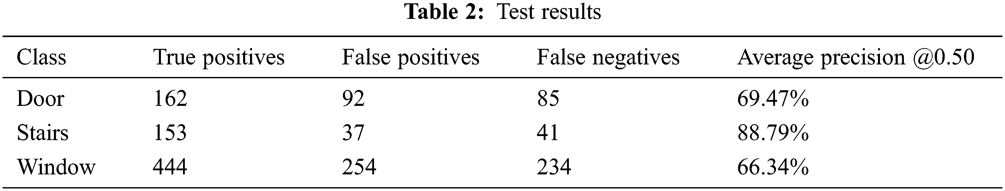
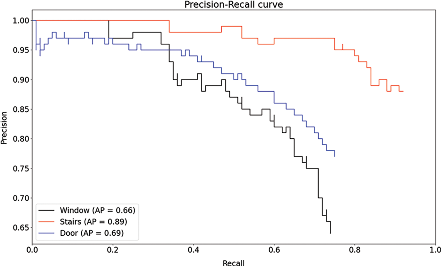
Figure 7: Precision-recall curves for three different classes
5.2 Tests in a Simulated Environment
The use of a simulator allows great freedom in the realization of experiments. Presenting a safe mode and realistic results might be the best way to implement new methods before experimenting with real flying robots. The Gazebo Simulation is one of the most popular simulation applications, which utilizes the Robot Operating System (ROS). It offers a variety of indoor and outdoor environments and the freedom to also create new environments. In this work, two different indoor environments consisting of windows and doors are used. As a flying robot, the quadrotor model of hector_gazebo is utilized. A LIDAR sensor (Hokuyo UTM-30LX) is used to obtain the laser data and a camera sensor (Generic camera) is used to obtain the optical data. These are then installed in the robot to locate obstacles and objects.
Since it is aimed to classify doors and windows and use their locations in the path planning algorithm, darknet_ros library is used with the camera data from the simulated quadrotor. The detected objects are also classified as open or closed with respect to what is defined in Section 3 and as seen in Fig. 8. Their positions are located according to the simulator’s coordinate system. For this purpose, a detected object’s position on the image and its distance value are used. The main purpose of the study is to use the proposed methods in real-time on a small quadrotor. For this, all the algorithms are run on an edge computing device (NVIDIA Jetson AGX Xavier).
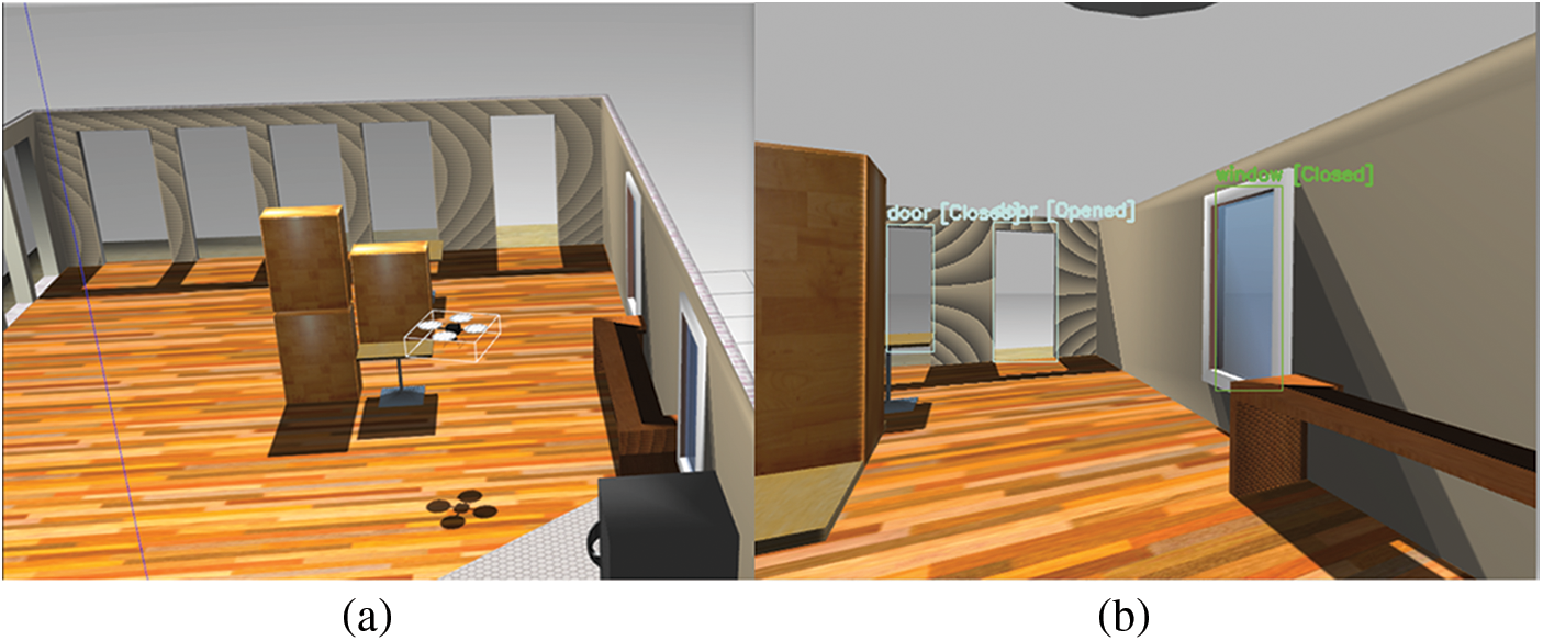
Figure 8: (a) View of the simulated environment from a wide-angle and quadrotor camera (b) identifying suitable (opened) gaps (windows or doors of the room) for the robot to pass through
To be able to see the performance of the proposed method, 16 different tests have been carried out in three different scenarios. In the first scenario, the robot is initially located in a closed space where there are obstacles between the target point and the quadrotor. The goal point is the green point seen in Fig. 9a, the red arrow represents the robot’s actual position, and the red line shows the path traveled by the robot. In this scenario, the robot took off from the starting blue point and reached its goal after going around and between the obstacles at a constant height using the proposed APF method. With a different map but the same scenario, the task is repeated successfully as shown in Fig. 9b. In these scenarios, reaching the goal point was also successful using the classical APF methods.
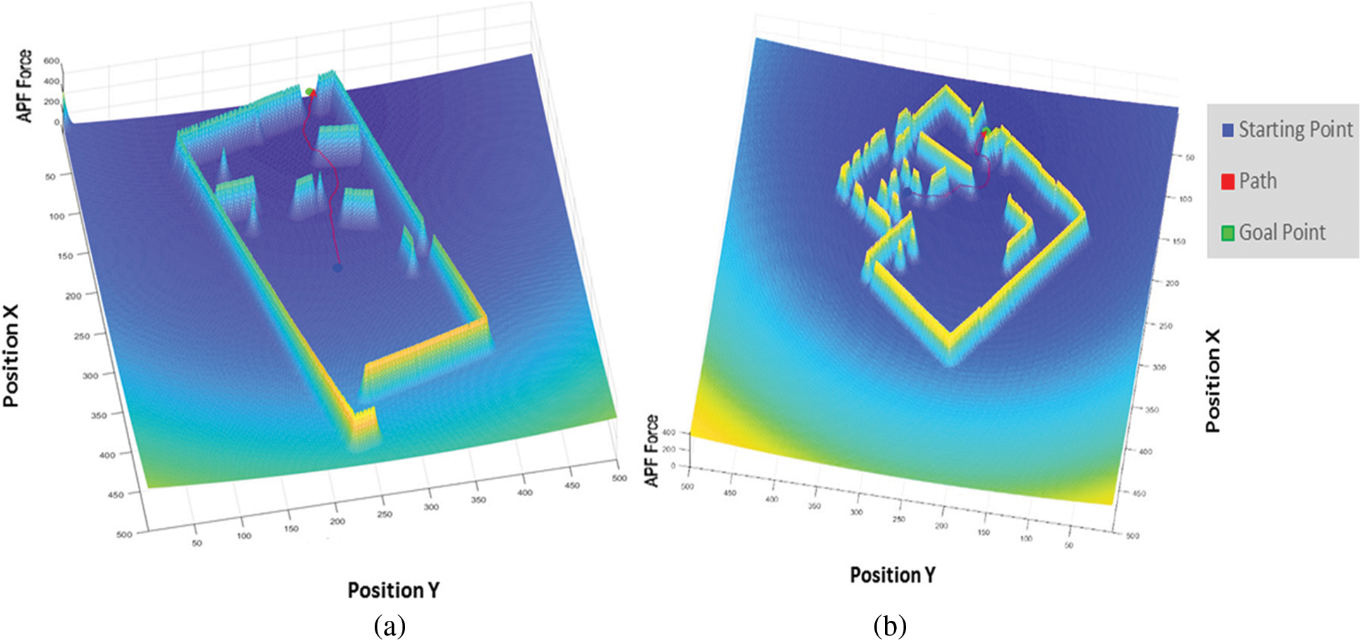
Figure 9: (a) APF based path planning due to total potential forces for a given target in first scenario. (b) APF based path planning in a different map
In the second scenario, the quadrotor is put in a random room and expected to discover the room and exit it. After it takes off, it starts to wander around until it completely maps the room. After this operation, it searches for a suitable crossing point. To have a more reliable understanding of the crossing point, the consistency of data is validated through capturing a number of image frames. Subsequently, the robot then determines that this object it has validated (the open door in Fig. 8) as a target point in order to leave the room. It successfully reaches this point using the improved APF method.
In the last scenario, a goal point is given outside the room. As shown in Fig. 10a, the robot composes a total force to guide itself to this point, but it goes into a vicious circle under the effects of repulsive and attractive points with APF methods in [11,13,26]. It oscillates when it gets close to the wall obstructing it from reaching the target. With the proposed method in this study, after being congested in a position, the quadrotor locates the open door in order to escape this position. It turns to the door and moves forward under the total forces of the obstacles and the target. Following its arrival at the door (the white point in Fig. 10b), it redetermines the goal point and navigates to that location as shown in Fig. 10b.
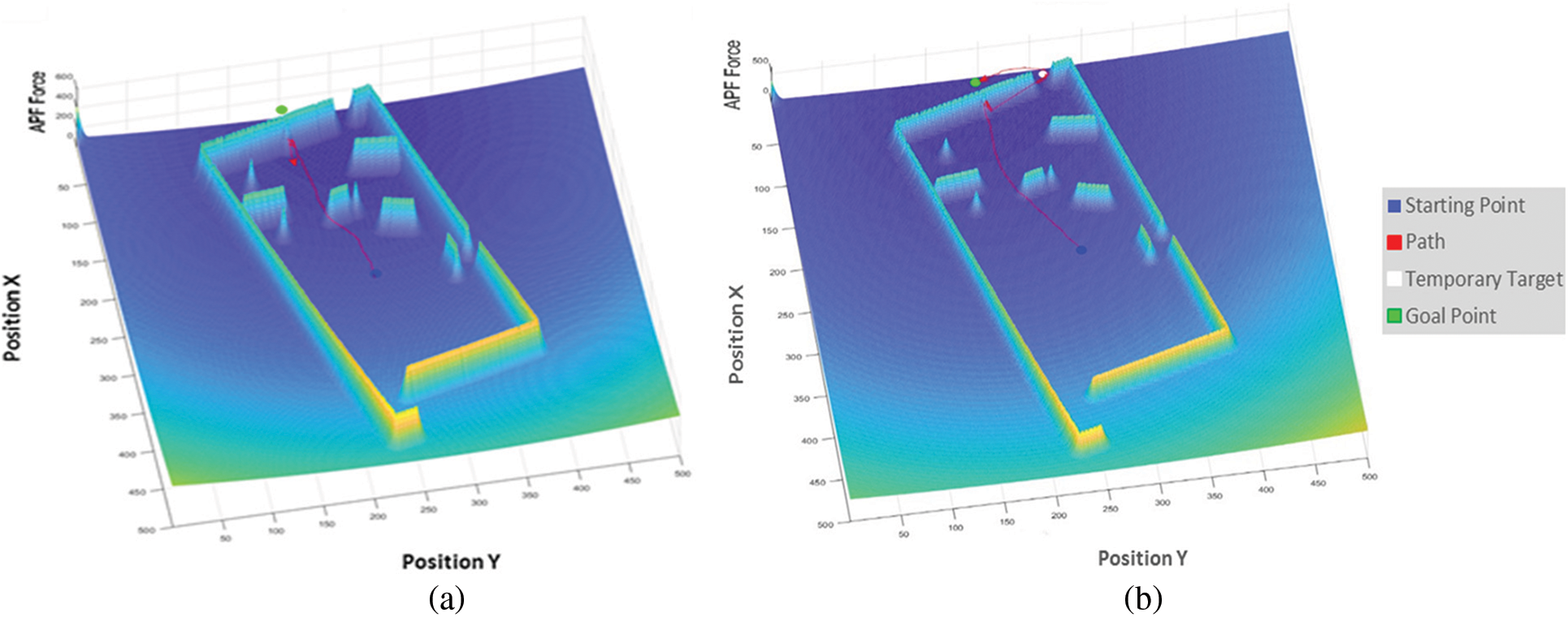
Figure 10: Total potential forces are used to route an autonomous UAV for the third scenario (a) APF based path planning (b) Path planning with an object detection process included with the APF method
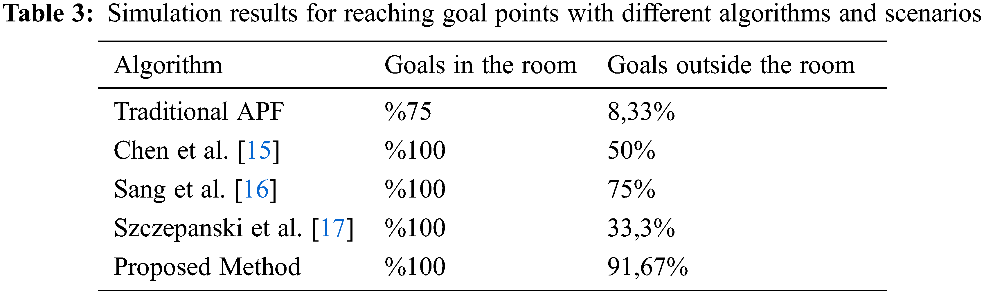
The goal point is moved into distinct positions inside and outside of the room to see the success of the proposed method. When the goal point is outside the room and not in the same direction as the room exit, it is not possible to navigate to goal points with the traditional APF methods. The logarithmic functions to define attractive and repulsive forces as well as using object detection in the path planning algorithm, provide a greater advantage for the robot to reach the goal point safely. The other improved APF methods show better performance compared to classical ones, yet our method shows superiority to these algorithms. As shown in Table 3, the quadrotor is able to reach the given goal points outside the room by 91%, 67% for different goal positions using the proposed method. Moreover, the proposed methods are tested on an edge computing device that is mountable on flying platforms. The device can detect the objects, compose the path plan, and update it in real-time.
One of the effective real-time navigation algorithms for unknown closed spaces, APF, has a crucial problem of falling into local minimum. In this study, by improving APF algorithm and detecting possible gateways, we presented a novel method for path planning in closed spaces in order to navigate between rooms. Benefiting from CNN and creating a hybrid dataset (including publicly available datasets and original images), possible gateways in a building such as windows and doors were successfully classified in real-time. With the help of registering LIDAR sensor and optical camera data in real-time, positions of detected objects, distances to the flying robot, and their widths were calculated to determine whether the gaps were suitable to pass through or not. Furthermore, it was discovered that this information can also be used for discovering and categorizing an unfamiliar location. The detected objects were tagged as open or closed and suitable doors or windows in a room were marked as temporary targets for use in the path planning of the robot. These temporary targets were then employed to provide the robot with options to escape local minimum points or to navigate between the rooms of an unknown building.
The performance of the proposed method was tested in a simulated environment by developing various scenarios. Although the object detection results show that the approach is successfully able to classify suitable openings, the dataset needs to be recategorized for closed areas and more images belonging to different circumstances need to be added to enhance the detection accuracy. In navigation tests, the flying robot is able to reach targets in the current room by avoiding obstacles similar to the other improved APF methods. On the other hand, it shows a superiority over the other methods in reaching the goals from outside the room, whereas classical APF approaches could not prevent the robot from oscillating at a certain point. In most cases, even with the methods in which APF and other navigation algorithms were combined, the robot was unable to reach the final targets if the crossing points were in the opposite direction from the goal. One of the drawbacks of our method was the creation of longer paths than some of the compared algorithms as the researched method used the crossing points only when it fell into the local minimum.
In this work, the APF based path planning approach is chosen as an example of an autonomous navigation solution. The success of the proposed method with different navigation algorithms and a specialized dataset for disaster zones will be studied in future works.
Acknowledgement: This article does not contain any studies with human participants or animals performed by any of the authors. All authors prepared the first draft, read and approved the final manuscript.
Funding Statement: The authors received no specific funding for this study.
Conflicts of Interest: The authors declare that they have no conflicts of interest to report regarding the present study.
References
1. I. Erkmen, A. M. Erkmen, F. Matsuno, R. Chatterjee and T. Kamegawa, “Snake robots to the rescue!,” IEEE Robotics & Automation Magazine, vol. 9, no. 3, pp. 17–25, 2002. [Google Scholar]
2. H. Tsukagoshi, M. Sasaki, A. Kitagawa and T. Tanaka, “Design of a higher jumping rescue robot with the optimized pneumatic drive,” in Proc. of the 2005 IEEE Int. Conf. on Robotics and Automation, Barcelona, Spain, pp. 1276–1283, 2005. [Google Scholar]
3. T. Y. Chou, M. L. Yeh, Y. C. Chen and Y. H. Chen, “Disaster monitoring and management by the unmanned aerial vehicle technology,” in ISPRS TC VII Symp., Vienna, Austria, pp. 137–142, 2010. [Google Scholar]
4. C. Sampedro, A. Rodriguez-Ramos, H. Bavle, A. Carrio, P. Puente et al., “A Fully-autonomous aerial robot for search and rescue applications in indoor environments using learning-based techniques,” Journal of Intelligent & Robotic Systems, vol. 95, no. 2, pp. 601–627, 2018. [Google Scholar]
5. D. D. Meneghetti, T. P. Homem, J. H. Oliveira, I. J. Silva, D. H. Perico et al., “Detecting soccer balls with reduced neural networks,” Journal of Intelligent & Robotic Systems, vol. 101, no. 3, pp. 1–15, 2021. [Google Scholar]
6. O. Alparslan and O. Cetin, “Fast and effective identification of window and door openings for UAVs’ indoor navigation,” in Int. Conf. on Unmanned Aircraft Systems (ICUAS), Athens, Greece, pp. 175–181, 2021. [Google Scholar]
7. S. K. Gopikrishnan, B. V. S. Shravan, H. Gole, P. Barve and L. Ravikumar, “Path planning algorithms: A comparative study,” in National Conf. on Space Transportation Systems, Houston, USA, 2011. [Google Scholar]
8. S. Scheggi and S. Misra, “An experimental comparison of path planning techniques applied to micro-sized magnetic agents,” in Int. Conf. on Manipulation, Automation and Robotics at Small Scales (MARSS), Paris, France, pp. 1–6, 2016. [Google Scholar]
9. S. Katiyar and A. Dutta, “Comparative analysis on path planning of ATR using RRT*, PSO, and modified APF in CG-space,” Proceedings of the Institution of Mechanical Engineers, Part C: Journal of Mechanical Engineering Science, vol. 236, no. 10, pp. 5663–5677, 2022. [Google Scholar]
10. P. Yan, Z. Yan, H. Zheng and J. Guo, “Real time robot path planning method based on improved artificial potential field method,” in 37th Chinese Control Conf. (CCC), Wuhan, China, pp. 4814–4820, 2018. [Google Scholar]
11. S. M. H. Rostami, A. K. Sangaiah and J. Wang, “Obstacle avoidance of mobile robots using modified artificial potential field algorithm,” J Wireless Com Network, vol. 70, no. 1, pp. 1–19, 2019. [Google Scholar]
12. O. Khatib, “Real-time obstacle avoidance for manipulators and mobile robots,” in IEEE Int. Conf. on Robotics and Automation, St. Louis, MO, USA, pp. 500–505, 1985. [Google Scholar]
13. I. Iswanto, A. Ma’arif, O. Wahyunggoro and A. Imam, “Artificial potential field algorithm implementation for quadrotor path planning,” International Journal of Advanced Computer Science and Applications, vol. 10, no. 8, pp. 575–585, 2019. [Google Scholar]
14. O. Cetin, S. Kurnaz, O. Kaynak and H. Temeltas, “Potential field-based navigation task for autonomous flight control of unmanned aerial vehicles,” International Journal of Automation and Control, vol. 5, no. 1, pp. 1–21, 2011. [Google Scholar]
15. Y. Chen, G. Bai, Y. Zhan, X. Hu and J. Liu, “Path planning and obstacle avoiding of the USV based on improved ACO-APF hybrid algorithm with adaptive early-warning,” IEEE Access, vol. 9, pp. 40728–40742, 2021. [Google Scholar]
16. H. Sang, Y. You, X. Sun, Y. Zhou and F. Liu, “The hybrid path planning algorithm based on improved A* and artificial potential field for unmanned surface vehicle formations,” Ocean Engineering, vol. 223, no. 108709, 2021. https://www.sciencedirect.com/science/article/pii/S002980182100144X. [Google Scholar]
17. R. Szczepanski, A. Bereit and T. Tarczewski, “Efficient local path planning algorithm using artificial potential field supported by augmented reality,” Energies, vol. 14, no. 20, pp. 6642, 2021. [Google Scholar]
18. A. Llopart, O. Ravn and N. A. Andersen, “Door and cabinet recognition using convolutional neural nets and real-time method fusion for handle detection and grasping,” in 3rd Int. Conf. on Control, Automation and Robotics (ICCAR), Nagoya, Japan, pp. 144–149, 2017. [Google Scholar]
19. T. H. Yuan, F. H. Hashim, W. M. D. W. Zaki and A. B. Huddin, “An automated 3D scanning algorithm using depth cameras for door detection,” in Int. Electronics Symp. (IES), Surabaya, Indonesia, pp. 58–61, 2015. [Google Scholar]
20. B. Quintana, S. A. Prieto, A. Adán and F. Bosché, “Door detection in 3D colored laser scans for autonomous indoor navigation,” in Int. Conf. on Indoor Positioning and Indoor Navigation (IPIN), Alcala de Henares, Spain, pp. 1–8, 2016. [Google Scholar]
21. B. Quintana, S. A. Prieto, A. Adán and F. Bosché, “Door detection in 3D coloured point clouds of indoor environments,” Automation in Construction, vol. 85, pp. 146–166, 2018. [Google Scholar]
22. N. Kwak, H. Arisumi and K. Yokoi, “Visual recognition of a door and its knob for a humanoid robot,” in 2011 IEEE Int. Conf. on Robotics and Automation, Shanghai, China, pp. 2079–2084, 2011. [Google Scholar]
23. A. Bochkovskiy, C. Wang and H. M. Liao, “Yolov4: Optimal speed and accuracy of object detection,” arXiv preprint arXiv:2004.10934, 2020. [Google Scholar]
24. A. Ozcan and O. Cetin, “A novel fusion method with thermal and RGB-D sensor data for human detection,” IEEE Access, vol. 10, pp. 66831–66843, 2022. [Google Scholar]
25. J. Baek, “Two-dimensional lidar sensor-based three-dimensional point cloud modeling method for identification of anomalies inside tube structures for future hypersonic transportation,” Sensors, vol. 20, no. 24, pp. 7235, 2020. [Google Scholar] [PubMed]
26. J. O. Kim and P. Khosla, “Real-time obstacle avoidance using harmonic potential functions,” IEEE Transactions on Robotics and Automation, vol. 8, no. 3, pp. 338–349, 1992. [Google Scholar]
27. A. Kuznetsova, H. Rom, N. Alldrin, J. Uijlings, I. Krasin et al., “The open images dataset v4,” International Journal of Computer Vision, vol. 128, no. 7, pp. 1956–1981, 2020. [Google Scholar]
28. M. Arduengo, C. Torras and L. Sentis, “Robust and adaptive door operation with a mobile robot,” Intelligent Service Robotics, vol. 14, no. 3, pp. 409–425, 2021. [Google Scholar]
29. U. Patil, “Deep learning based stair detection and statistical image filtering for autonomous stair climbing,” in Third IEEE Int. Conf. on Robotic Computing (IRC), Naples, Italy, pp. 159–166, 2019. [Google Scholar]
Cite This Article
 Copyright © 2023 The Author(s). Published by Tech Science Press.
This work is licensed under a Creative Commons Attribution 4.0 International License , which permits unrestricted use, distribution, and reproduction in any medium, provided the original work is properly cited.
 Downloads
 Citation Tools