
 Submit a Paper
 Propose a Special lssue
 Open Access
ARTICLE

A Real-Time Localization Algorithm for Unmanned Aerial Vehicle Based on Continuous Images Processing
1 School of Information and Communication Engineering, Nanjing Institute of Technology, Nanjing, 211167, China
2 School of Communication Engineering, Tongda College of Nanjing University of Posts and Telecommunications, Yangzhou, 225127, China
3 School of Mathematics and Physics, Nanjing Institute of Technology, Nanjing, 211167, China
* Corresponding Author: Peng Geng. Email:
Journal on Artificial Intelligence 2024, 6, 43-52. https://doi.org/10.32604/jai.2024.047642
Received 13 November 2023; Accepted 27 February 2024; Issue published 28 March 2024
 View Full Text
 Download PDF
Abstract
This article presents a real-time localization method for Unmanned Aerial Vehicles (UAVs) based on continuous image processing. The proposed method employs the Scale Invariant Feature Transform (SIFT) algorithm to identify key points in multi-scale space and generate descriptor vectors to match identical objects across multiple images. These corresponding points in the image provide pixel positions, which can be combined with transformation equations, allow for the calculation of the UAV’s actual ground position. Additionally, the physical coordinates of matching points in the image can be obtained, corresponding to the UAV’s physical coordinates. The method achieves real-time positioning and tracking during UAV flight, with experimental results demonstrating that within an acceptable error range, the UAV coordinates calculated using the proposed algorithm are consistent with the actual coordinates. The maximum error along the x-axis, y-axis, and z-axis is 4.501 cm, with the horizontal error exhibiting high stationarity and the vertical error having a low average value of 0.041 cm. The real-time positioning algorithm presented in this article possesses characteristics such as simplicity, ease of implementation, and low error, making it suitable for UAVs with limited computational processing power.Keywords
Unmanned Aerial Vehicles (UAVs) are becoming increasingly popular in applications such as surveillance, reconnaissance, mapping, and car-UAV collaborative driving. Unlike pilot-navigated UAVs, autonomous control systems heavily rely on accurate feedback of the vehicle’s position. Current common technologies for UAV localization include Global Positioning System (GPS) [1,2], laser radar [3,4], ultrasound [5], Ultra-Wideband (UWB) [6], radio frequency [7,8], and visual methods [9,10]. While GPS is commonly employed for obtaining location information in open areas, its performance degrades when there is interference with GPS signals. Laser radar has limited range and can be influenced by environmental factors [11]. Ultrasonic localization techniques advanced through systems relying on environmental and sensor detection [12], but these methods suffer from slow processing speed and are not suitable for high-speed car-UAV collaborative driving scenarios. UWB and RF localization methods are used only under specific environmental conditions.
In contrast, visual localization offers real-time and generalizable capabilities, making it useful for both GPS-denied environments and tasks that do not require large datasets. The use of UAVs to capture images and perform localization analysis belongs to the technical category of machine vision. Firstly, the image signal is obtained through the built-in camera and other shooting equipment on the UAV, and transmitted to the onboard image processing chip or program. After analysis, the color and distribution information of the captured object can be obtained, and then converted into digital image signals. Digital image processing programs can also be used to analyze the captured object images, apply graphic knowledge to recognize and interact with the environment, and guide UAV localization.
This article utilizes multiple image processing methods for real-time localization of UAVs. Several major aspects are studied in this article, as described below:
• Proposed a continuous method for real-time localization of UAVs utilizing visual sensors to detect their location.
• Based on SIFT algorithm [13], the detection of key points in multi-scale space is achieved, and the vector information of key points is obtained for matching the same objects in different images.
• Corresponding points in the images provide pixel locations that, combined with a conversion equation, allow calculation of the actual ground position of the UAV. Physical coordinates of the matched points in the image relative to the UAV’s physical coordinates can also be obtained. By utilizing the above methods, real-time positioning and tracking of UAVs during flight have been achieved.
The rest of this article is organized as follows. The current state of research on real-time UAV localization algorithm is presented in Section 2. Section 3 gives the implementation scheme. Section 4 carries out program testing and analysis. The summary of the article comes from Section 5.
In recent years, real-time UAV localization algorithms based on continuous image processing have made certain progress. The common method is to use the SIFT algorithm to detect key points. The SIFT algorithm can find key points in multiple scale spaces and generate descriptor vectors for matching the same objects in different images. By matching the position of key points in the image, the actual ground position of the UAV can be calculated. In addition to the SIFT algorithm, there are also other image processing algorithms used for UAV localization. For example, the ORB (Oriented FAST and Rotated BRIEF) algorithm [14] is a fast feature detection and description algorithm that can provide faster speed than the SIFT algorithm, but may sacrifice some accuracy [15]. The SURF (Speeded Up Robust Features) algorithm [16] is also commonly used for UAV localization, which combines the advantages of the SIFT algorithm with the speed advantage of the FAST feature detection algorithm. However, the SURF algorithm consumes a lot of resources and is more suitable for hardware systems with sufficient computing resources. For embedded systems or real-time applications with limited resources, this is a limitation [17]. In addition, the increasingly improved research on path planning [18] and tracking of UAVs [19], as well as UAV attitude and altitude control, has also promoted the accuracy of positioning.
Although real-time UAV localization algorithms based on continuous image processing have achieved some success, they still face some challenges. Firstly, factors such as changes in lighting, weather conditions, and flight altitude can affect the quality of images and the detection of feature points [20]. Secondly, how to convert pixel coordinates to actual geographic coordinates is also a problem that needs to be solved [10]. In addition, how to improve positioning accuracy and speed is also an important direction for future research [21]. To overcome these challenges, researchers are exploring various new methods and technologies. For example, some studies use deep learning techniques to improve the detection and matching performance of feature points [22–24]. Some studies also consider using multimodal sensor fusion to improve positioning accuracy and robustness [25–27].
Overall, real-time localization of UAVs based on continuous image processing is an active research field, and there are many unresolved issues waiting for us to solve. This article systematically implements real-time positioning of UAVs based on the SIFT algorithm, which has lower resource consumption and higher real-time performance, making it more suitable for embedded UAV systems. The experimental results show that within the allowable range of error, the UAV coordinates calculated by this algorithm match the true coordinates.
The proposed continuous-image-processing-based real-time localization algorithm for UAVs provides real-time positioning capabilities during flight, improving localization accuracy and enhancing UAV control, which can lead to innovative applications such as autonomous interaction between UAVs and cars, terrain recognition, and object tracking. The implementation scheme is shown in Fig. 1.
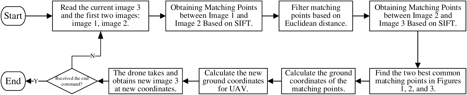
Figure 1: System processing flowchart
To achieve the above scheme, the following steps are taken:
Step One: Utilize the onboard camera of the UAV to capture images and input the current image3 as well as the previous two images image1 and image2.
Step Two: Acquire matches between image1 and image2, and between image2 and image3 using the Scale-Invariant Feature Transform (SIFT) algorithm. The detailed process involves the following steps:
(1) Construct Gaussian Difference Pyramid:
• Downsample the input images (e.g., image1 and image2) to create a pyramid of images.
• Apply different-sized Gaussian filters (with varying σ) at each scale in the pyramid to generate Gaussian pyramids.
• Compute the difference between adjacent layers in the Gaussian pyramids to form Gaussian difference pyramids.
(2) Detect Keypoints:
• Search for extremal points in each layer of the Gaussian difference pyramid. These points are stable in both scale space and orientation, making them suitable for use as feature points.
• Use a contrast thresholding method to filter out weak keypoint candidates.
(3) Precisely Locate Keypoints:
• For each detected candidate keypoint, fit a second-order polynomial to precisely calculate its location.
(4) Assign Keypoint Orientation:
• Compute the gradient histogram in the neighborhood of each keypoint and assign the direction with the highest gradient magnitude to the keypoint.
(5) Generate Descriptor Vectors:
• Based on the pixel values surrounding each keypoint, generate a unique 128-dimensional or higher-dimensional descriptor vector for each keypoint.
(6) Match Descriptors:
• Use Euclidean [28] to compare the descriptors of all keypoints from the two images.
• Select the best matching pairs based on a predetermined threshold, using techniques like ratio testing or cross-checking to eliminate false matches.
Repeat the above process and handle the matching between image2 and image3 separately. It should be noted that the SIFT algorithm is independent in finding matching points between multiple images, so each pair of images needs to perform the above process separately.
Step Three: Filter the matches between image1 and image2 using Euclidean distance. Due to the potential for mismatches and excessive matches produced by the SIFT algorithm, a distance metric is needed to identify the best keypoints. Distance metrics measure the distance between points in space; larger values suggest greater differences between objects. The standard adopted here is Euclidean distance, a commonly used distance measurement representing the absolute distance between objects in multi-dimensional space. In three-dimensional space, the Euclidean distance between points a(x1, y1, z1) and b(x2, y2, z2) is expressed by formula (1). In the localization algorithm, stronger matches should be selected for coordinate calculations, i.e., those with the smallest Euclidean distance.
Note that since image1 and image2 contain all content that is repeated in image3, image2 and image3 contain more object content than image1. As such, the matches between image2 and image3 may not necessarily exist in image1. In this case, the matches between image1 and image2 can be filtered using Euclidean distance to ensure they exist in image3. Filtering cannot be performed based on Euclidean distance between image2 and image3 as it would result in missing corresponding matches in image1.
Step Four: Identify the two best common matches among image1, image2, and image3. Simple Euclidean distance evaluation suffices to filter out the most similar matches between two images. However, localization requires at least three consecutive images. The process follows these steps:
(1) Obtain the position
(2) Capture the position
(3) Only the first two positions need to be known, after which the UAV’s position can be calculated by program. When the UAV moves to position
(4) To find
As can be seen from the above, the matching points used for calculation must exist in all three consecutive images. Therefore, Euclidean distance cannot be the only criterion for selecting suitable matching points. Since the matching points are obtained by comparing two images, in order to obtain a common matching point for the three images, the second image in the middle must be used as the standard. After obtaining the matching points MatchPoints1 between image1 and image2 and MatchPoints2 between image2 and image3, if MatchPoints1 and MatchPoints2 have the same coordinates on the second image, they are the common matching points of the three images. Combined with the Euclidean distance of the matching points, the coordinates of the two matching points suitable for calculation can be filtered out.
Step Five: Use coordinate transformation algorithm
which
Step Six: Calculate the ground coordinates of the UAV using the coordinate transformation algorithm A2. Given that the ground coordinates of two different matching points in the image captured by the UAV at a certain location are
which
Step Seven: If the UAV receives the stop positioning information, it will end and return. Otherwise, new images will be collected and proceed to Step one.
4 Program Testing and Analysis
Set the initial coordinate position of the UAV in the air to (0, 0, 90) (unit: Centimeters). The program first performs image matching based on the first group of images (image1, image2, and image3), filters two common matching points, and calculates the coordinates of the matching points. The results are shown in Table 1.

Since the relative position between matching points remains constant within each group, their pixel coordinates in image3 will be relatively fixed. From Table 1, there is approximately an 86-pixel difference along the x-axis (calculated by subtracting the x-coordinate column entries) and 1.8-pixel difference along the y-axis (calculated by subtracting the y-coordinate column entries). Despite minor discrepancies along the y-axis, these differences cause minimal deviation in the display.
After computing the data for the first group, take image2 as the beginning of the next group, forming the group of image2, image3, and image4. The results are presented in Table 2.

Once the second group computations are complete, proceed with image3, image4, and image5 as the third group. Continuing similarly, the nth group consists of images image(n), image(n+1), and image(n+2). Ultimately, the UAV’s ground coordinates can be determined, displayed for the first seven groups in Table 3.

Ground-truth UAV position data is obtained via measurement, compared to calculated coordinates from the localization algorithm, listed in Table 4. The comparison between the actual coordinates and calculated coordinates of the UAV on the x, y and z axes are shown in Figs. 2–4, respectively.
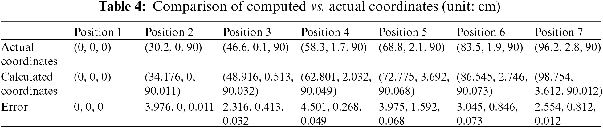

Figure 2: Comparison of actual coordinates and calculated coordinates on the x-axis

Figure 3: Comparison of actual coordinates and calculated coordinates on the y-axis

Figure 4: The difference between the actual and calculated coordinates on the z-axis
Fig. 2 represents the geographic coordinate deviation of UAV on the x-axis. It can be seen that the error amplitude is relatively balanced at each test point, which means it is easier to perform parameter calibration in the later stage. Fig. 3 represents the geographic coordinate deviation of UAV on the y-axis. Contrary to the characteristics on the x-axis, its error amplitude is not stable, indicating that the algorithm needs to be optimized in this regard. Fig. 4 represents the geographic coordinate deviation of UAV on the z-axis. It can be seen that the difference between the first and sixth points steadily increases, and by the seventh point, the error value regresses to a lower range, proving that the algorithm has a certain degree of error correction.
Specifically, observations from the experiment reveal maximum errors of 4.501 cm along the x, y and z axes. Horizontal (x & y-axis) errors exhibit higher variability with an average error of 2.4298 cm. Vertical direction error (z-axis) exhibits lower average error of 0.041 cm. Contributing factors include camera parameter errors, errors associated with the UAV’s velocity during imaging (movement between image captures), rounding errors during computation and measurement errors. Overall, this approach demonstrates promising localization accuracy.
Overall, the UAV real-time positioning algorithm proposed in this article for continuous image acquisition and processing has the characteristics of simplicity, ease of implementation, and low error, making it suitable for UAVs with low computational processing capabilities. However, it should be noted that due to limitations, this experiment only collected images of stationary objects, and the recognition and localization of moving objects are still under study. In addition, comparisons with other algorithms will be reflected in subsequent research.
This article uses visual sensors to detect the position of unmanned aerial vehicles. A real-time localization algorithm for unmanned aerial vehicles using continuous image acquisition and processing has been proposed. This algorithm can achieve accurate and stable positioning of unmanned aerial vehicles in urban environments or with severe signal interference. Real-time positioning and tracking functions can help UAVs better perceive the surrounding environment, and improve the accuracy and safety of flight control. It can be applied to the cooperative driving scene of UAVs and autonomous vehicles, expanding the application scene of UAVs.
Acknowledgement: None.
Funding Statement: This study was supported by National Natural Science Foundation of China Project (41972111) and the Second Tibetan Plateau Scientific Expedition and Research Program (STEP), Ministry of Science and Technology, China (2019QZKK020604).
Author Contributions: The authors confirm contribution to the paper as follows: Study conception and design: Peng Geng, Annan Yang; data collection: Yan Liu; analysis and interpretation of results: Peng Geng; draft manuscript preparation: Annan Yang, Yan Liu. All authors reviewed the results and approved the final version of the manuscript.
Availability of Data and Materials: Not applicable.
Conflicts of Interest: The authors declare that they have no conflicts of interest to report regarding the present study.
References
1. P. Radoglou-Grammatikis, P. Sarigiannidis, T. Lagkas, and I. D. Moscholios, “A compilation of UAV applications for precision agriculture,” Comput. Netw., vol. 172, no. 3, pp. 107148, 2020. doi: 10.1016/j.comnet.2020.107148. [Google Scholar] [CrossRef]
2. B. Zhu, B. J. Zhang, and Q. Ge, “A nonlinear model predictive control based control method to quadrotor landing on moving platform,” Cognit. Comput. Syst., vol. 5, no. 2, pp. 118–131, 2023. doi: 10.1049/ccs2.12081. [Google Scholar] [CrossRef]
3. S. Schraml, M. Hubner, P. Taupe, M. Hofstätter, P. Amon and D. Rothbacher, “Real-time gamma radioactive source localization by data fusion of 3D-LiDAR terrain scan and radiation data from semi-autonomous UAV flights,” Sens., vol. 22, no. 23, pp. 9198, 2022. doi: 10.3390/s22239198. [Google Scholar] [CrossRef]
4. H. Wen, W. Nie, X. Yang, and M. Zhou, “UAV indoor localization using 3D laser radar,” in 2022 IEEE 10th Asia-Pacific Conf. Antennas Propagat. (APCAP), IEEE, 2022, pp. 1–2. [Google Scholar]
5. B. Yang, E. Yang, L. Yu, and C. Niu, “Ultrasonic—and IMU—based high-precision UAV localization for the low-cost autonomous inspection in oil and gas pressure vessels,” IEEE Trans. Industr. Inform., vol. 19, no. 10, pp. 10523–10534, 2023. doi: 10.1109/TII.2023.3240874. [Google Scholar] [CrossRef]
6. B. Yang, E. Yang, L. Yu, and A. Loeliger, “High-precision UWB-based localisation for UAV in extremely confined environments,” IEEE Sens. J., vol. 22, no. 1, pp. 1020–1029, 2021. doi: 10.1109/JSEN.2021.3130724. [Google Scholar] [CrossRef]
7. D. S. Jasrotia and M. J. Nene, “Localisation using UAV in RFID and sensor network environment: Needs and challenges,” in 2019 Int. Conf. Comput., Commun., Intell. Syst. (ICCCIS), IEEE, 2019, pp. 274–279. [Google Scholar]
8. B. Yang and E. Yang, “A survey on radio frequency based precise localisation technology for UAV in GPS-denied environment,” J. Intell. Robot Syst., vol. 103, no. 3, pp. 1–30, 2021. doi: 10.1007/s10846-021-01500-4. [Google Scholar] [CrossRef]
9. F. Wang et al., “UAV navigation in large-scale GPS-denied bridge environments using fiducial marker-corrected stereo visual-inertial localization,” Automat. Constr., vol. 156, no. 3, pp. 105139, 2023. doi: 10.1016/j.autcon.2023.105139. [Google Scholar] [CrossRef]
10. A. Couturier and M. A. Akhloufi, “A review on absolute visual localization for UAV,” Robot Autonom. Syst., vol. 135, no. 3, pp. 103666, 2021. doi: 10.1016/j.robot.2020.103666. [Google Scholar] [CrossRef]
11. D. Wang, C. Watkins, and H. Xie, “MEMS mirrors for LiDAR: A review,” Micromach., vol. 11, no. 5, pp. 456, 2020. doi: 10.3390/mi11050456. [Google Scholar] [PubMed] [CrossRef]
12. Q. Chen, Y. Xie, and G. Sl, “Sensing system of environmental perception technologies for driverless vehicle: A review of state of the art and challenges,” Sens. Actuat. A: Phys., vol. 319, no. 3, pp. 112566, 2021. doi: 10.1016/j.sna.2021.112566. [Google Scholar] [CrossRef]
13. J. Wu, Z. Cui, V. S. Sheng, P. Zhao, D. Su and S. Gong, “A comparative study of SIFT and its variants,” Meas. Sci. Rev., vol. 13, no. 3, pp. 122–131, 2013. doi: 10.2478/msr-2013-0021. [Google Scholar] [CrossRef]
14. E. Rublee, V. Rabaud, K. Konolige, and G. Bradski, “ORB: An efficient alternative to SIFT or SURF,” in 2011 Int. Conf. Comput. Vis., IEEE, 2011, pp. 2564–2571. [Google Scholar]
15. A. K. Al Tamimi, A. Qasaimeh, and K. Qaddoum, “Offline signature recognition system using oriented FAST and rotated BRIEF,” Int. J. Electric. Comput. Eng. (IJECE), vol. 11, no. 5, pp. 4095–4103, 2021. doi: 10.11591/ijece.v11i5.pp4095-4103. [Google Scholar] [CrossRef]
16. H. Bay, T. Tuytelaars, and L. van Gool, “SURF: Speeded up robust features,” in Comput. Vis.—ECCV 2006: 9th Eur. Conf. Comput. Vis., Graz, Austria, Berlin Heidelberg, Springer, 2006, pp. 404–417. [Google Scholar]
17. S. Katoch, V. Singh, and U. S. Tiwary, “Indian sign language recognition system using SURF with SVM and CNN,” Array, vol. 14, no. 1, pp. 100141, 2022. doi: 10.1016/j.array.2022.100141. [Google Scholar] [CrossRef]
18. E. Belge, A. Altan, and R. Hacıoğlu, “Metaheuristic optimization-based path planning and tracking of quadcopter for payload hold-release mission,” Electron., vol. 11, no. 8, pp. 1208, 2022. doi: 10.3390/electronics11081208. [Google Scholar] [CrossRef]
19. A. Altan, “Performance of metaheuristic optimization algorithms based on swarm intelligence in attitude and altitude control of unmanned aerial vehicle for path following,” in 2020 4th Int. Symp. Multidiscip. Studies Innovat. Technol. (ISMSIT), IEEE, 2020, pp. 1–6. [Google Scholar]
20. S. Lin, L. Jin, and Z. Chen, “Real-time monocular vision system for UAV autonomous landing in outdoor low-illumination environments,” Sens., vol. 21, no. 18, pp. 6226, 2021. doi: 10.3390/s21186226. [Google Scholar] [PubMed] [CrossRef]
21. Y. Li, F. Shu, B. Shi, X. Cheng, Y. Song and J. Wang, “Enhanced RSS-based UAV localization via trajectory and multi-base stations,” IEEE Commun. Lett., vol. 25, no. 6, pp. 1881–1885, 2021. doi: 10.1109/LCOMM.2021.3061104. [Google Scholar] [CrossRef]
22. C. Sandamini et al., “A review of indoor positioning systems for UAV localization with machine learning algorithms,” Electron., vol. 12, no. 7, pp. 1533, 2023. doi: 10.3390/electronics12071533. [Google Scholar] [CrossRef]
23. D. Li et al., “A novel approach for the 3D localization of branch picking points based on deep learning applied to longan harvesting UAVs,” Comput. Electron. Agric., vol. 199, no. 4, pp. 107191, 2022. doi: 10.1016/j.compag.2022.107191. [Google Scholar] [CrossRef]
24. Y. Ren and Z. Wang, “A novel scene matching algorithm via deep learning for vision-based UAV absolute localization,” in 2022 Int. Conf. Mach. Learn., Cloud Comput. Intell. Min. (MLCCIM), IEEE, 2022, pp. 211–218. [Google Scholar]
25. A. Gupta and X. Fernando, “Simultaneous localization and mapping (slam) and data fusion in unmanned aerial vehicles: Recent advances and challenges,” Drones, vol. 6, no. 4, pp. 85, 2022. doi: 10.3390/drones6040085. [Google Scholar] [CrossRef]
26. S. Bultmann, J. Quenzel, and S. Behnke, “Real-time multi-modal semantic fusion on unmanned aerial vehicles,” in 2021 Eur. Conf. Mobile Robots (ECMR), IEEE, 2021, pp. 1–8. [Google Scholar]
27. R. Zhu, M. Yang, L. Yin, F. Wu, and Y. Yang, “UAV’s status is worth considering: A fusion representations matching method for geo-localization,” Sens., vol. 23, no. 2, pp. 1–18, 2023. doi: 10.3390/s23020720. [Google Scholar] [PubMed] [CrossRef]
28. R. Huang, C. Cui, W. Sun, and D. Towey, “Poster: Is euclidean distance the best distance measurement for adaptive random testing?,” in 2020 IEEE 13th Int. Conf. Softw. Test., Valid. Verif. (ICST), IEEE, 2020, pp. 406–409. [Google Scholar]
Cite This Article
 Copyright © 2024 The Author(s). Published by Tech Science Press.
This work is licensed under a Creative Commons Attribution 4.0 International License , which permits unrestricted use, distribution, and reproduction in any medium, provided the original work is properly cited.
 Downloads
 Citation Tools