 Open Access
REVIEW
A Review on Auxetic Polymeric Materials: Synthetic Methodology, Characterization and their Applications
Defence Materials and Stores Research and Development Establishment DMSRDE PO, Kanpur-208013, India
* Corresponding Author: e-mail:
Journal of Polymer Materials 2023, 40(3-4), 227-269. https://doi.org/10.32381/JPM.2023.40.3-4.8
Abstract
Over the last three decades, there has been considerable interest in the captivating mechanical properties displayed by auxetic materials, highlighting the advantages stemming from their distinct negative Poisson's ratio. The negative Poisson's ratio observed in auxetic polymeric materials is a result of the distinctive geometries of their unit cells. These unit cells, encompassing structures such as chiral, re-entrant, and rotating rigid configurations, are carefully engineered to collectively generate the desired auxetic behaviour. This comprehensive review article explores the field of auxetic polymeric materials, offering a detailed exploration of their geometries, fabrication methods, mechanical properties, and characterisation. The diverse applications of these materials in impact/ballistic, acoustic, automotive, biomedical, sports, shape memory, strain sensors, electromagnetic shielding, smart filters, and rehabilitation fields are thoroughly examined. Furthermore, the article emphasises the significance of auxetic behaviour in enhancing mechanical performance while shedding light on the challenges and limitations associated with large-scale fabrication of auxetic materials.Keywords
Auxetic polymeric materials are man-made materials with negative Poisson's ratio that are resulted from the specific unit cell geometries used in their construction. The unit cells (re-entrant, chiral, rotating rigid, etc.) are designed to work together to produce the desired auxetic behaviour. This unique property is not only related to the bulk properties of the materials, but also stems from their controlled tailored architectures.[1-3] These materials have attracted significant attention due to their exceptional and distinctive properties for novel applications such as in impact/ballistic, acoustic, automotive, shape memory, strain sensor, electromagnetic shielding, smart filters, cushioning, biomedical, and sports etc. The Poisson's ratio (υ) value is determined by the ratio of transverse strain (ɛT) with the lateral strain (ɛL), as expressed by the subsequent equation.[4]
Additional properties associated with auxetic materials include modulus,[5] indentation,[5, 6] and fracture toughness.[5,7] The interrelation between Poisson's ratio (υ) and shear modulus (G) is depicted in expression 2, in which E represents Young's modulus. As υ approaches -1, G tends towards infinity.
Equation 3 reveals the interrelation between Poisson's ratio (υ) and bulk modulus (K). Equation 4 outlines the interrelation between indentation resistance (H) and Poisson's ratio (υ), for Hertzian indentation, γ = 2/3 and for uniform pressure distribution γ = 1. Thanks to these exceptional mechanical properties, auxetic materials have discovered numerous innovative applications.[8-11]
The unique auxetic behaviour in natural materials, such as pyrolytic graphite, α-cristobalite, cat skin, and zeolites, was discovered around 150 years ago.[12-17] In 1987, Lakes discovered auxetic materials based on open-cell polyurethane foams with a Poisson's ratio value of -0.7.[18] Later, auxetic behaviour was observed in allotropes of carbon[19], polymeric foams,[20] porous polymeric materials,[21, 22] laminates,[23, 24] and materials composed of crystals with flexible crystal structures.[25] In-depth studies have revealed that this class of materials possesses improved mechanical properties, such as indentation toughness, resilience, shear strength, and damping performance.[26-28]
Over an extended period of time, several fabrication methods have been devised for constructing auxetic architectures, such as volumetric compression,[29] 3D printing,[30] mold-assisted techniques,[31] molecular-level techniques,[32,33] and polymer composites.[34] However, developing auxetic materials at a large scale using these techniques is crucial and challenging. The only way to overcome these limitations is to design auxetic structures at the molecular level. Some efforts have been made by scientists to create molecular-level auxetic materials, but to date, the process is limited to lab-scale only.
The present review offers a comprehensive discussion on auxetic polymeric materials, with a special emphasis on auxetic geometries, auxetic polymeric materials, methodologies for the fabrication of auxetic polymeric materials, mechanical properties, factors affecting mechanical properties, and characterisation. The next section covers the applications of auxetic polymeric materials. Additionally, a table-formatted summary of auxetic polymeric materials is presented. Lastly, conclusions and final remarks on auxetic polymeric materials are discussed.
In recent decades, extensive research and exploration have been conducted on various geometric structures and materials capable of demonstrating auxetic effects. These investigations have focused on understanding their mechanical properties and potential applications.[35,36] The unique auxetic behaviour observed in polymers originates from the meticulous design of their precisely controlled architecture. To provide a comprehensive overview, this section is divided into two main parts: (i) the exploration of auxetic geometrical structures and auxetic unit cell structures, and (ii) the investigation of auxetic polymeric materials.
2.1 Auxetic geometrical structure
Several geometrical structures and models have been proposed and developed that can exhibit an auxetic response[37]. Depending on the mechanism of deformation, structures exhibiting auxetic properties can be classified as: 1) re-entrant, 2) rotating units, and 3) chiral.
In recent times, the re-entrant honeycomb structure has garnered significant attention as the most extensively studied auxetic structure. The original concept of the re-entrant honeycomb design was presented by Gibson et al. in 1982.[38] Subsequently, in 1996, Master and Evans extensively explored the investigation of the auxetic effect in the 2D re-entrant honeycomb structure[39]. Since then, numerous structural modifications have been proposed to enhance or alter the auxetic mechanical properties.[40,41] Other reported auxetic re-entrant geometries encompass arrowhead, stars, and cut missing ribs.[42-45] The underlying mechanism driving the auxetic behaviour in the re-entrant design involves the diagonal ribs to move in varying directions in response to applied loads (Fig. 1a-e).[46]
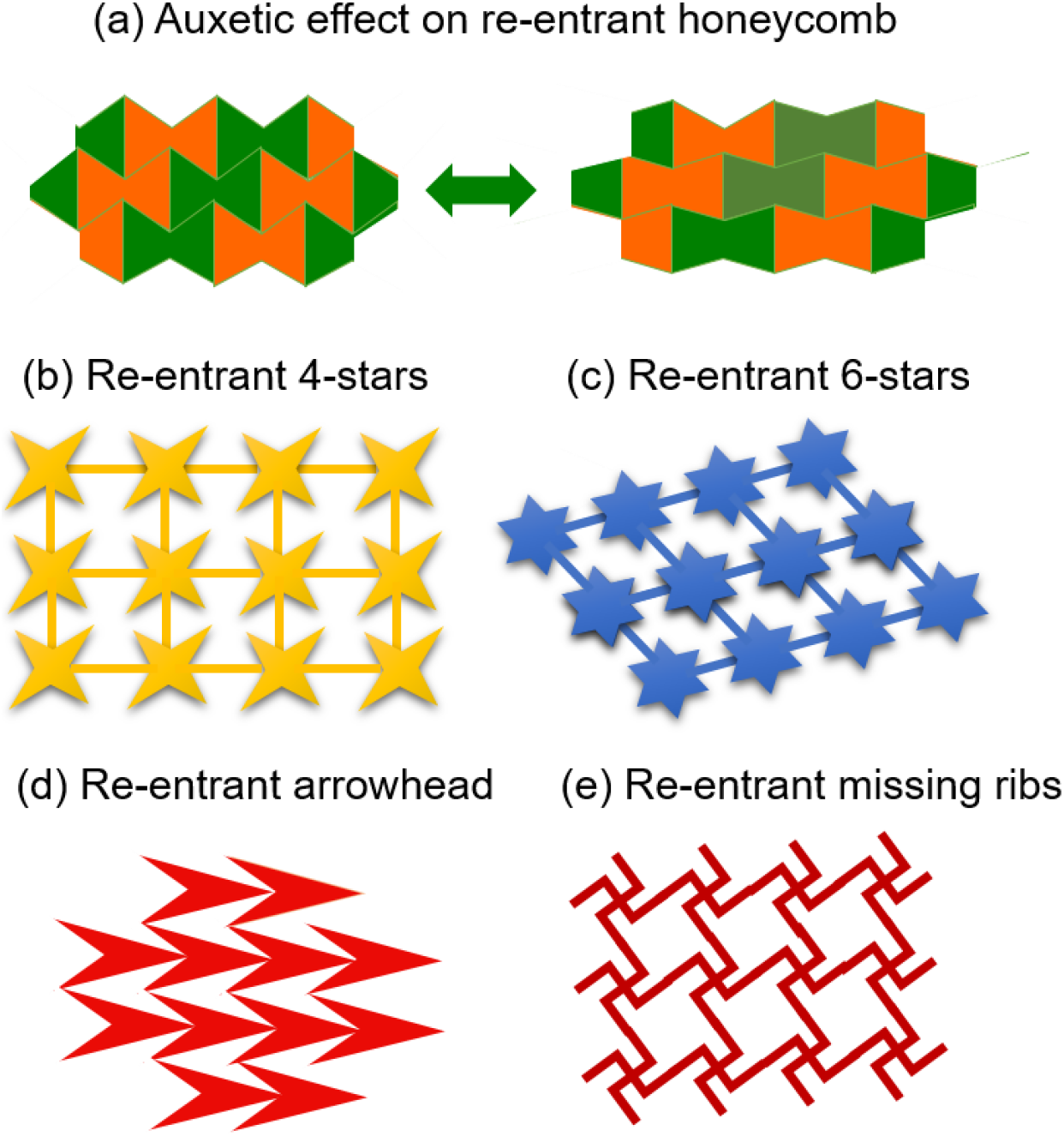
Fig. 1.: Auxetic re-entrant geometries (a) re-entrant honeycomb geometries showing auxetic behavior; (b) re-entrant 4-stars; (c) re-entrant 6-stars; (d) re-entrant arrowhead; (e) re-entrant missing ribs.
The pioneering work conducted by Grima and Evans in 2000 explored the utilisation of rotating rigid units. This marked the first investigation into the auxetic behaviour achieved through the rotation of rigid polygons in response to external loading.[47] Using this concept, several polymers with auxetic behaviour have been developed, such as rotating triangles,[48] rotating rectangles,[49] rotating rhombi and parallelograms,[49] rotating squares,[50] and rotating tetrahedrons[51] (Fig. 2).
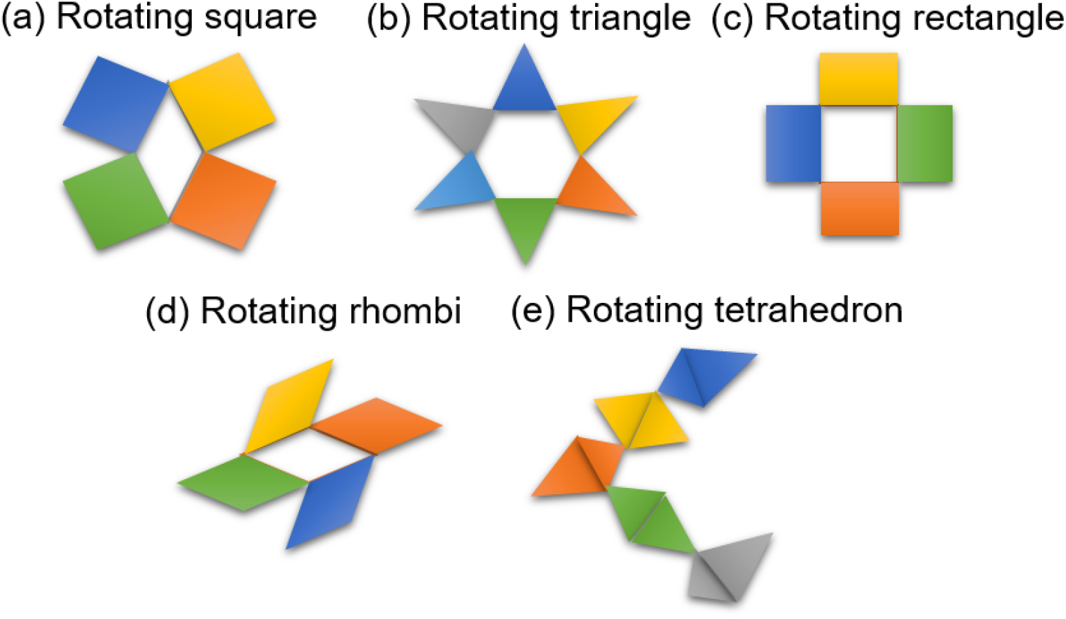
Fig. 2.: The unit cell of the (a) rotating square; (b) rotating triangle; (c) rotating rectangle; (d) rotating rhombi; (e) rotating tetrahedron.
Chiral auxetic structures typically consist of ligaments (ribs) that are tangentially connected to central rigid rings. These structures possess a non-superimposable nature when compared to their mirror images. In contrast, non-chiral or anti-chiral structures are characterised by ligaments attached to the same side of the central ring, exhibiting reflective symmetry in their geometry (Fig. 3)[52]. The auxetic behaviour is obtained by the central ring rotation in response to compressive loading or external tensile loading, resulting in ligament wrapping or unwrapping around the rings[53]. The reported auxetic chiral units include hexachiral honeycomb[54], anti-chiral honeycomb[55], meta-chiral systems[56], chiral unit with re-entrant core cell[57], tetra-chiral, and hexa-chiral geometries.[58]
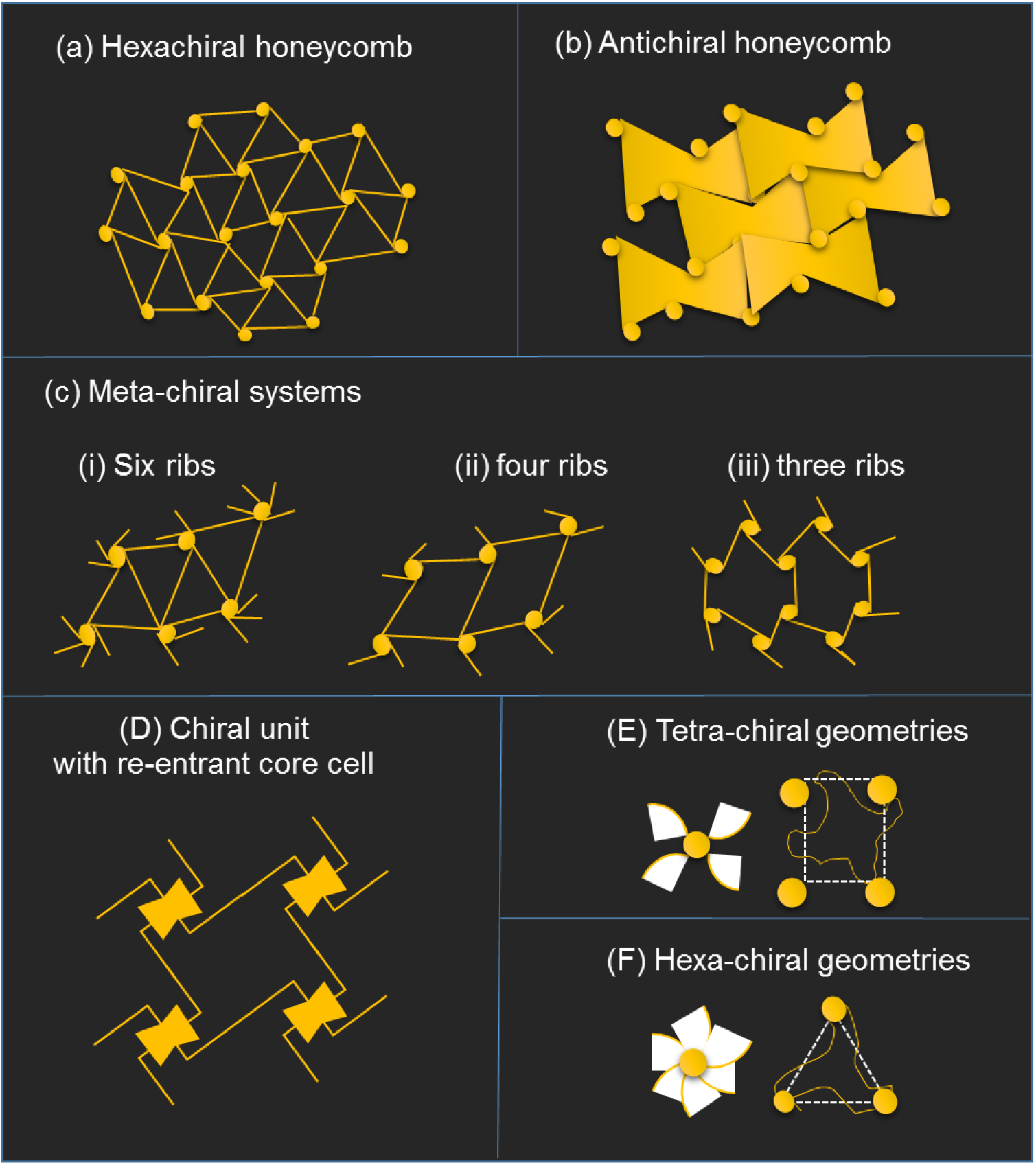
Fig. 3.: Chiral design: (a) Hexa-chiral honeycomb system; (b) Anti-chiral honeycomb system; (c) Meta-chiral systems with (i) 6 ribs; (ii) 4 ribs; (iii) 3 ribs; (d) Chiral unit with re-entrant core cell; (e) Tetra-chiral unit with arc-shaped ligament; (f) Hexa-chiral system with arc-shaped ligament.
2.2 Auxetic polymeric materials
Although the concept of auxeticity in polymeric materials has existed for some time, it has only recently gained significance. Presently, several auxetic polymer-based materials have been created, including foams/sponges, films, hydrogels, aeraogels, and molecular-level auxetic polymers, which have exhibited improved properties over non-auxetic materials and have profound applications in diverse areas such as defense, sports, and medicine. In 1987, Lakes developed the first auxetic polyurethane (PU) foam with re-entrant geometries and a Poisson's ratio value of -0.7.[18] Since then, numerous studies have been conducted on auxetic foams, leading to the proposal of several modifications.[59,60] For instance, a 3D silver nanowire conductor with a buckled structure was fabricated using polyurethane (PU) sponges as templates (Fig. 4).[61] Due to the buckled structure, the developed 3D conductor displayed auxetic properties and excellent conformability to curved surfaces. Similarly, polyurethane-based auxetic graphene foams with buckled structures were developed, where the buckled structure and auxeticity were introduced through a triaxial post-compression treatment process.[62]
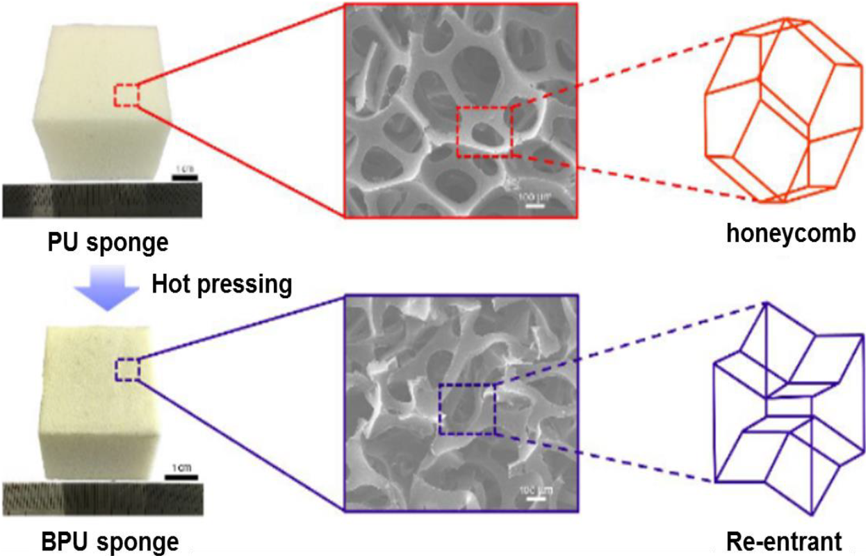
Fig. 4.: A comparison between non-auxetic polyurethane (PU) foam and auxetic buckled polyurethane (BPU) foam. Reproduced with permission.[61] Copyright 2019, American Chemical Society.
Compared to other polymeric materials, auxetic films are generally more durable and possess enhanced mechanical properties. Han et al. developed hierarchical-patterned films using poly(dimethylsiloxane) (PDMS) and silver (Ag) flakes.[63] The developed films exhibited enhanced mechanical properties attributed to the hierarchical-patterned auxetic structure. Similarly, a polyvinylidene fluoride (PVDF) film with three 2D auxetic rotating geometries (quadrilateral, triangular, and an "I"-shaped) was developed (Fig. 5). Interestingly, they also developed triboelectric nanogenerators (TENGs) by incorporating the PVDF film into polydimethylsiloxane (PDMS) material.[64] The auxetic TENGs showed improved output voltage, high stability, and potential application as wearable sensors.

Fig. 5.: Polyvinylidene fluoride (PVDF) film with three 2D NPR structures (a) rotating quadrilateral; (b) rotating triangular; (c) "I"-shaped structure). Reproduced with permission.[64] Copyright 2022, American Chemical Society.
Evans and Caddock first created a microporous Polymeric material using expanded polytetrafluoroethylene (PTFE) in 1989, which had an negative passion ratio (NPR) value of -12.[65] This material has a structure composed of interconnected nodules and fibrils, and the auxetic behaviour is attributed to the translation of nodules facilitated by the hinging of the fibrils. Since then, several auxetic polymers, including ultrahigh molecular weight polyethylene (UHMWPE),[66] Polypropylene (PP),[67] nylon,[68] polyacrylonitrile (PAN),[69] and polyester,[70] have been developed based on this concept. Bhullar et al. used the melt-electrospinning technique to produce rotating square-rigid geometries-based auxetic microfiber sheets of Polycaprolactone (PCL).[71] Additionally, the research team fabricated auxetic sheets into cylindrical-shaped tubes for the production of auxetic stents (Fig. 6a, b). The same group later developed a rotating square-rigid geometry-based auxetic nanofiber membrane of polycaprolactone (PCL) for biomedical applications.[72]
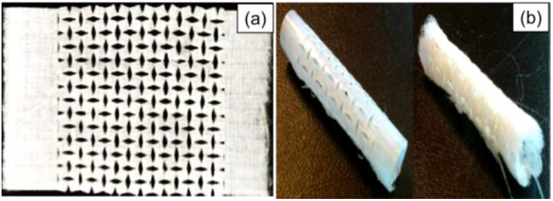
Fig. 6.: (a) Micromachined PCL microfiber. (b) PCL microfiber stents. Reproduced with permission.[71] Copyright 2015, Taylor & Francis Online.
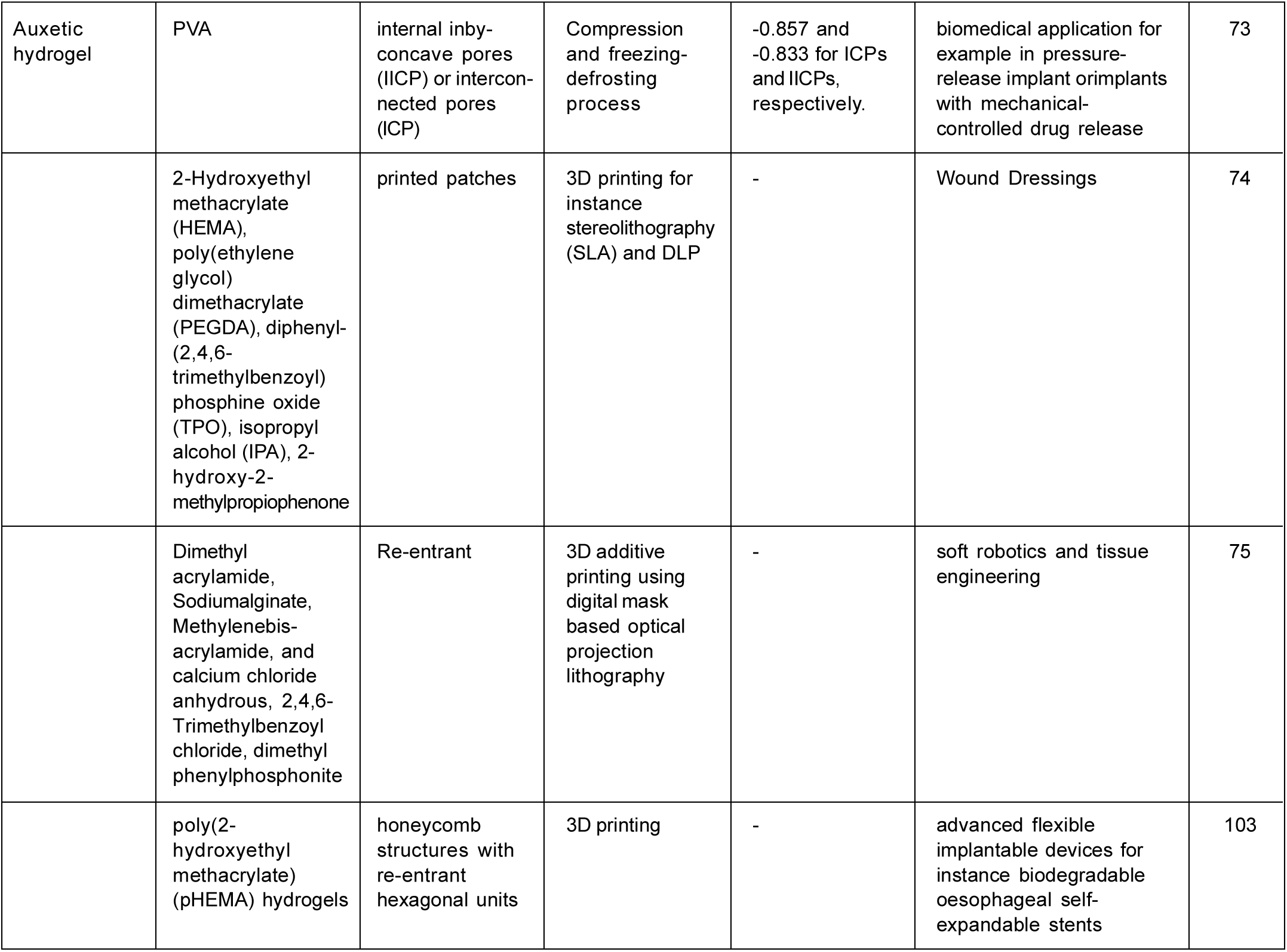
Polymeric hydrogels are 3D porous networks formed by cross-linking polymer chains either physically or chemically. The introduction of auxeticity into polymeric hydrogels results in controlled swelling behaviour, uniform porosity, and improved mechanical properties.[73-75] Ma et al. developed PVA-based auxetic hydrogels with interconnected pores (ICP) and Internal Inby-concave Pores (IICP) (Fig. 7). The study showed the effect of shape, size, and distribution of pores on the value of the Poisson ratio, varying from -0.667 to -1.000 and -0.294 to -0.833 for ICP and IICP, respectively.[73] Patches with auxetic structures were created using Digital Light Processing (DLP) printing techniques.[74] Double-network (DN) hydrogels were synthesised and applied to fabricate user-defined 2D and 3D auxetic structures using optical projection lithography (Fig. 8).[75]

Fig. 7.: The SEM images of the PVA hydrogels + surfactant: (a) templated closed cells; (b) internal inby-concave pores (IICP); (c) interconnected pores (ICP). Reproduced with permission.[73] Copyright 2013, Elsevier.
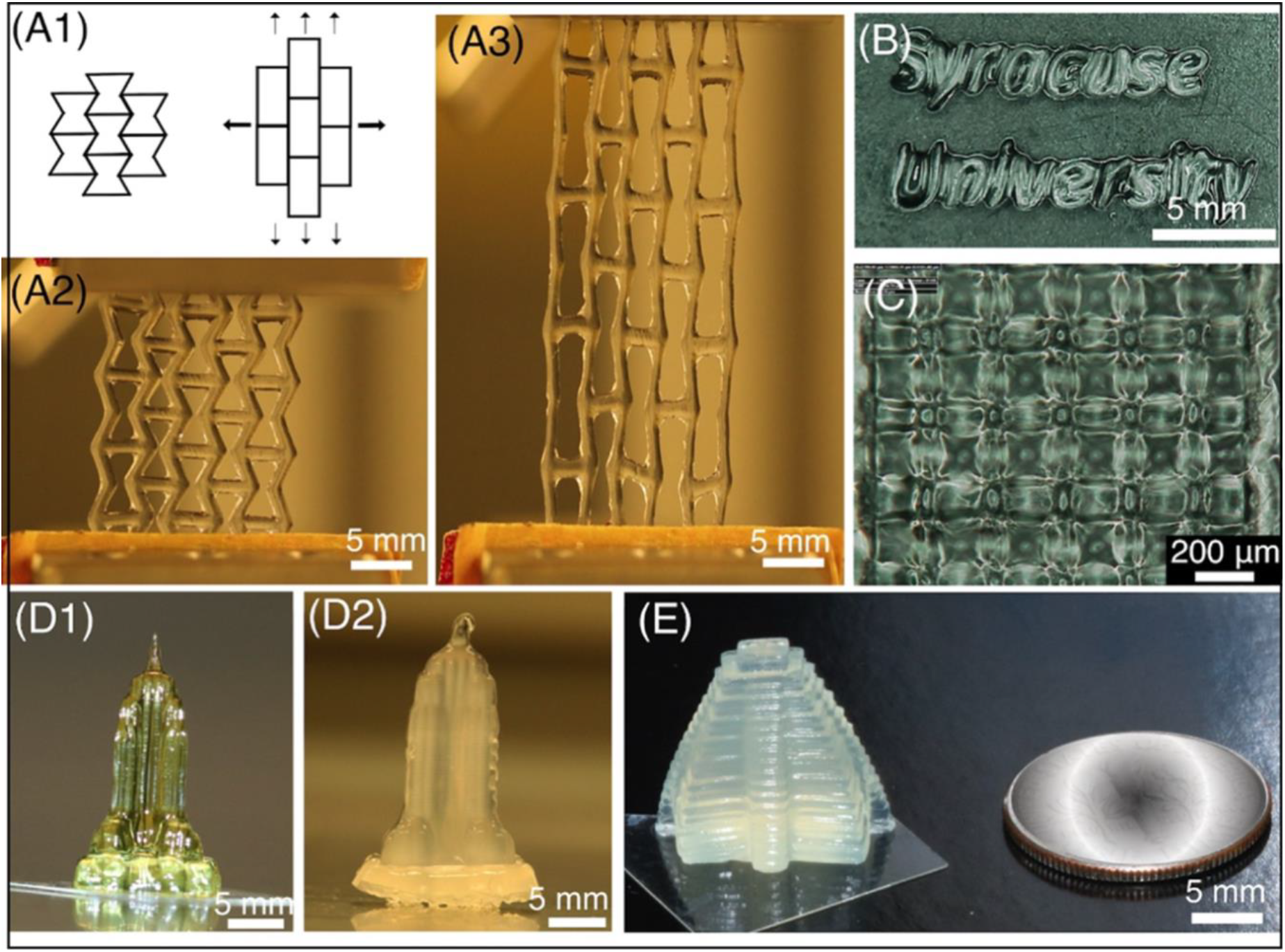
Fig. 8.: (A1) Cartoon illustration of a 2D auxetic structure with re-entrant geometries. The different fabricated versions of 2D auxetic structure with re-entrant geometries using DN gel and calcium solution (A2-E). The image, labeled A2, depicts the 2D auxetic structure before stretching, while the image, labeled A3, shows the structure after stretching. Image B displays the words "Syracuse University." The log-pile structure with a resolution of 120 μm is displayed in image C. Empire State Building prior to and subsequent to immersion in the calcium solution, correspondingly,while image E shows a 3D printed Mayan pyramid structure made using DN gel and dipped into the calcium solution. Reproduced with permission.[75] Copyright 2020, American Chemical Society.
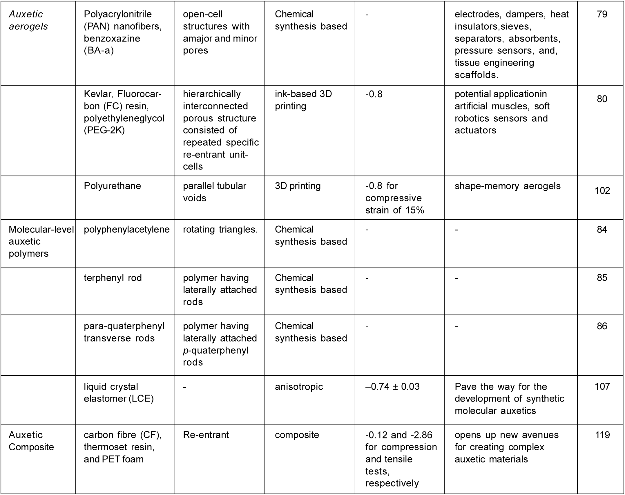
Aerogels are porous materials with an extremely low density, containing air or a vacuum in their pores.[76-78] In the literature, there are several reports on aerogels based on polymeric materials. However, reports on aerogels based on auxetic polymeric materials are rare. Si et al. presented nanofibrous aerogels with a hierarchical cellular structure.[79] The developed nanofibrous aerogels exhibited auxetic properties attributed to the inverting of the cell walls. Another 3D-printed auxetic architecture based on Kevlar aerogel showed superior mechanical properties, multifunctionalities, and a tunable Poisson ratio.[80]
2.2.6 Molecular-level auxetic polymers
In the literature, porous auxetic polymeric materials have been thoroughly investigated. However, increased porosity may limit their application due to poor strength and structural instability. Additionally, inconsistent sample production, complicated procedures, costlier fabrication techniques, etc., are major limitations of conventional fabrication methodologies. This necessitates the development of polymeric materials with auxeticity at the molecular-level design.
Wojciechowski et al. first attempted to develop a molecular-level auxetic material using a 2D system of hard cyclic hexamers.[81] Later, several molecular-level auxetic designs were proposed based on macroscopic re-entrant structures.[82] Based on the re-entrant geometric unit, two molecular structures, (n,m)-reflexyne [82], and double-arrow-like molecules,[83] were proposed. Garima and Evans developed a self-expanding polytriangles-2-yne network-based auxetic molecular structure.[84]
A successful approach at the molecular level was developed to create auxetic materials by incorporating laterally attached rods, specifically ter-phenyl units, into the main polymer chain (Fig. 9a).[85] Initially, these laterally attached rods align in parallel with the main polymer chain before any stretching occurs. However, when subjected to a tensile force, these rods undergo a positional change from parallel to perpendicular relative to the direction of tension. In the fully stretched main chain of polymer, these ter-phenyls form a 60° angle. In a subsequent experiment, the same research group reported the development of another molecular-level auxetic polymer by substituting ter-phenyl rods with para-quaterphenylrods.[86] When fully stretched, this newly designed polymer can rotate up to 75° in relation to the main chain of polymer, effectively increasing the separation between neighboring chains (Fig. 9b).
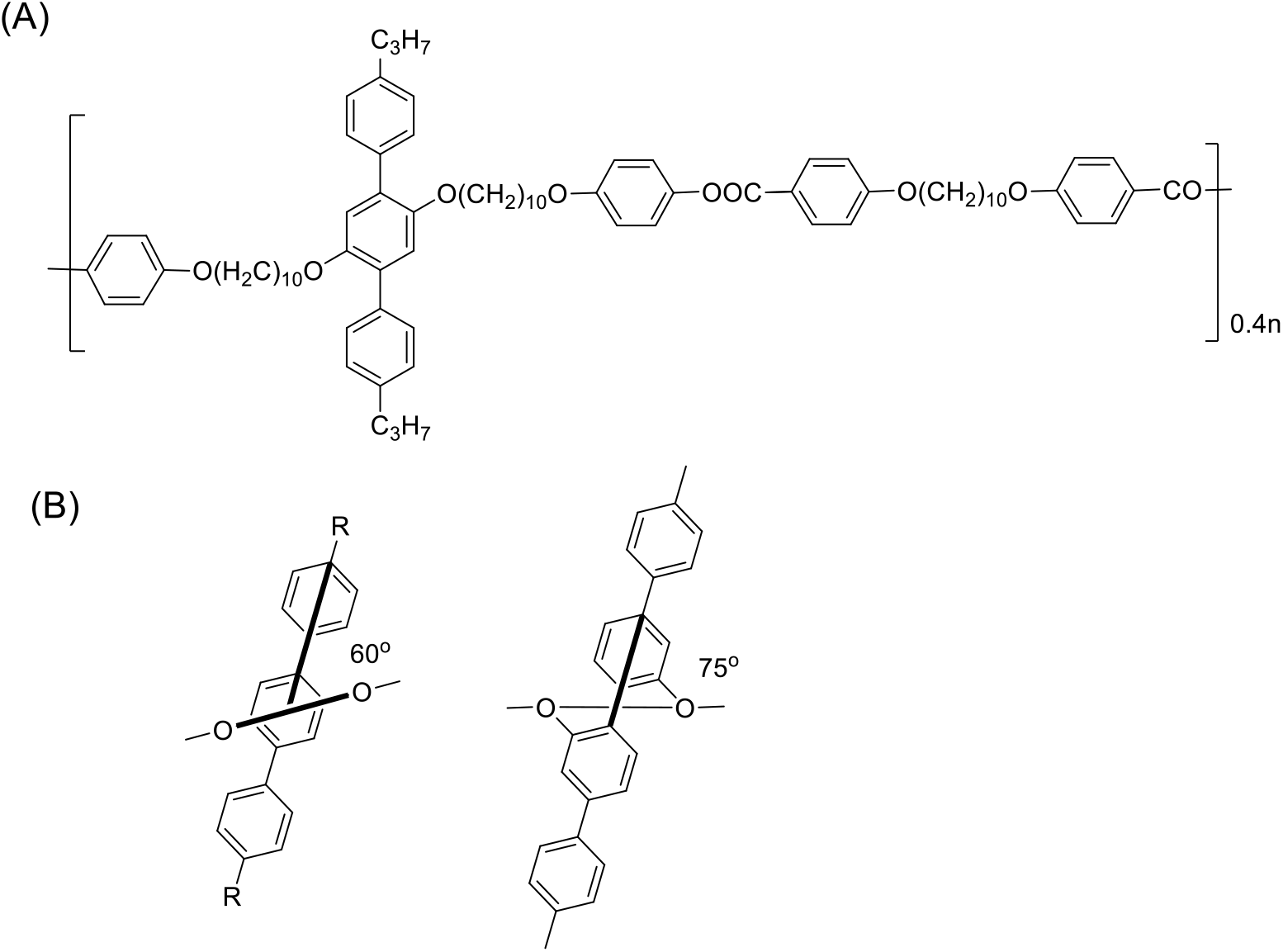
Fig. 9.: (A) Chemical structure of ter-phenyl unit attached molecular polymer. Reproduced with permission.[85] Copyright 1998, American Chemical Society. (B) Enhancement of transverse-rod reorientation is achieved by altering the site connectivity from ter-phenyl to quater-phenyl unit. Reproduced with permission.[86] Copyright 2005, Wiley-VCH.
Specialized fabrication methods have been utilised in the literature to convert different polymeric materials, such as foams and hydrogels, into auxetic polymeric materials. Among these methods, the most commonly studied approach involves a three-stage procedure consisting of stress compression (for re-entrant geometries), a heating step (for preserving the geometries), and finally cooling (to freeze the structure). This technique, developed by Lakes, is used to transform traditional open-cell polyurethane foams into auxetic polyurethane foams.[18] However, the drawback of this technique is the inconsistent production of samples, largely due to inadequate placement of the internal unit cells during compression. One potential solution to overcome these issues is 3D printing, an advanced method for producing auxetic materials that can achieve repeatability in the auxetic process.[87, 88] Other techniques for designing auxetic structures at various scales include the mold method, molecular-level design, and polymer composites.[89]
The technique for producing auxetic foam involves a series of steps. First, the foam is subjected to tri-axial compression, leading to the creation of re-entrant geometries due to rib buckling, as illustrated in Fig. 10.[29] The re-entrant geometries are then preserved through heating, and finally, they are frozen in place during the cooling stage.[90] While this is the most commonly studied approach, there are other methods that can be used, such as using solvents[91] or CO2[92] to substitute the heating phase. Moreover, substituting a rigid mold with a vacuum bag is another option that has been explored in the literature.[93,94] Investigating alternative materials for constructing auxetic foam, researchers have explored the creation of an auxetic composite foam with shape memory properties using polyurethane and epoxy resin.[95] Fan et al. utilised a steam penetration and condensation process to synthesize an auxetic foam composed of closed-cell polyethylene (PE) foam and polyvinyl chloride foam.[96] Duncan et al. examined the influence of compression, temperature, and duration on the structural stability, Poisson's ratio, and Young's modulus of auxetic PU foam.[97]
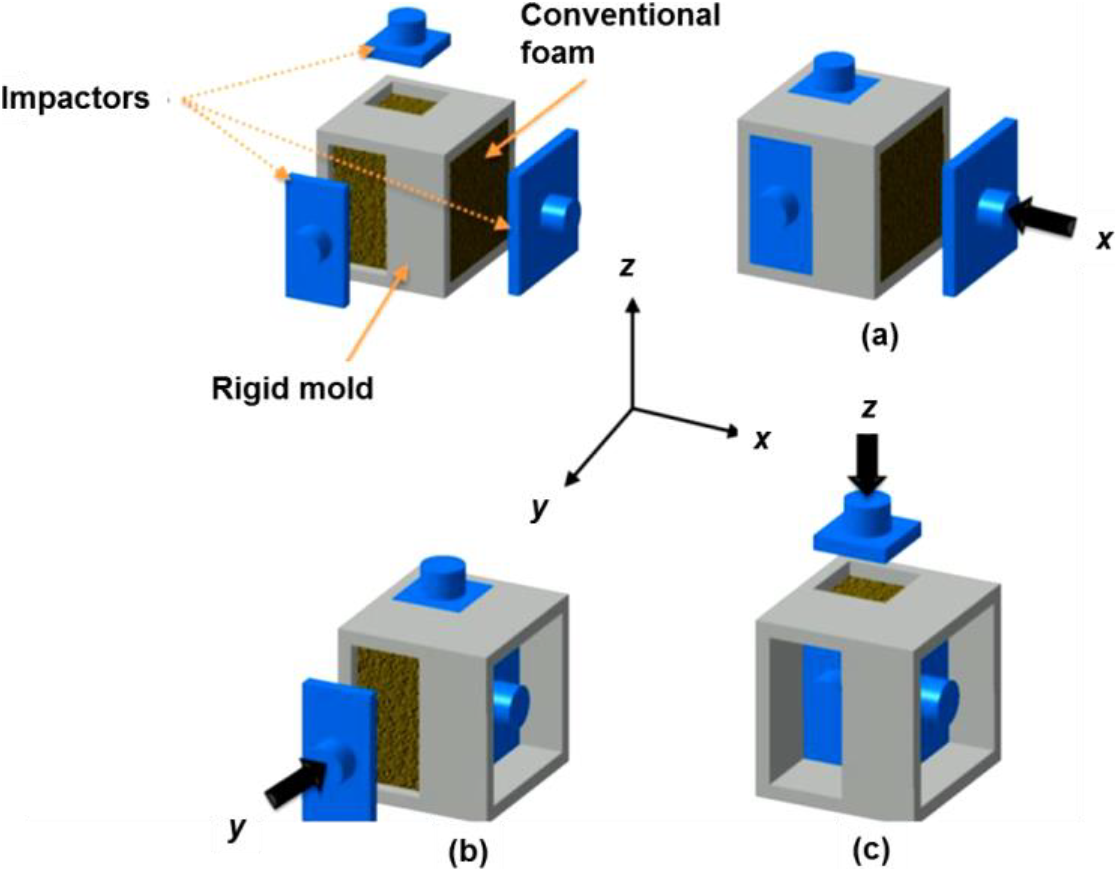
Fig. 10.: Images showing volumetric tri-axial compression. Reproduced with permission.[29] Copyright 2019, Wiley-VCH.
In recent years, there has been a notable expansion of literature dedicated to the fields of 3D and 4D printing, which underscores the swift progress witnessed in these technological domains.[4, 98-103] 3D printing has now firmly established itself as a widely employed manufacturing technique, capable of crafting intricate and customisable objects across various scales, spanning from macroscopic to microscopic and even nanoscopic levels. This process hinges on layered manufacturing methods, wherein the desired geometry is conceived through the utilisation of Computer-Aided Design (CAD) software. This digital representation is subsequently translated into a recognisable Additive Manufacturing (AM) file format, which is further segmented into discrete layers. The final design is then constructed through the sequential deposition of these layers using 3D printing technology.[4] The widespread adoption of 3D printing has been propelled by its cost-effectiveness, facilitated by the increasing accessibility of budget-friendly 3D printers, as well as compatible printing software and hardware.[4] 4D printing, as an extension of 3D printing, introduces a compelling temporal dimension to the equation. This innovative paradigm entails the fabrication of objects endowed with the capacity to undergo dynamic transformations in their shape, properties, or functionality over time, in response to external stimuli such as variations in temperature, moisture levels, or exposure to light.[4,98-103]
These techniques encompass Digital Light Processing (DLP), Stereolithography (SLA), Selective Laser Sintering (SLS), Fused Deposition Modeling (FDM), Melt Electro-writing (MEW), and multiphoton lithography (MPL). The production of 3D polymeric Polyethylene Glycol Diacrylate (PEGDA) scaffolds with auxetic characterstics for biomedical applications involved the utilisation of stereolithography techniques[98]. The process involved loading photocurable prepolymers into a syringe pump, followed by printing models using Computer-Aided Design (CAD) software. To create a layered-hybrid lattice, a photosensitive resin-0116 was used through the digital light processing method.[99] Protective pads with honeycomb, re-entrant hexagonal, and arrowhead geometries were fabricated using the FDM method and CAD model, employing thermoplastic PU and polylactic acid (PLA) as polymer materials. The developed arrowhead and hexagonal re-entrant structures had Poisson ratios of -0.47 and -1.82, respectively.[100] The Melt Electro-Writing (MEW) method was applied to design a missing rib type auxetic structure and PCL patches.[101] The 3D printing at the macroscale was employed to augment the shape-memory properties and auxetic behaviour, which manifested Poisson ratio of -0.8 at compressive strain of 15%. The shape-memory response was enhanced through 3D printing at the macroscale, resulting Poisson ratio of-0.8 (approx.) at 15% compressive strain.[102] Another instance of a 3D printed auxetic structure was documented, which utilised a hydrogel composed of methacrylated cellulose nanocrystals-poly(2-hydroxyethyl methacrylate) (CNCMA-PHEMA) (Fig. 11A).[103] The resulting re-entrant honeycomb structure demonstrated excellent stretchability and toughness, displaying auxetic behaviour (Fig. 11B).
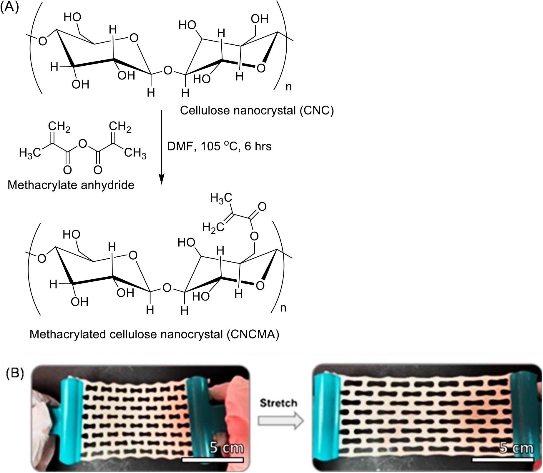
Fig. 11.: (A) Scheme for methacrylated cellulose nanocrystal(CNCMA) synthesis. (B) Demonstration of auxetic behavior of CNCMA hydrogel. Reproduced with permission.[103] Copyright 2021, American Chemical Society.
A diacrylate-poly(ethylene glycol) gel coated with silver nanowires (Ag NWs) was created for sensor applications using a printed photomask technique.[104] The fabrication process involves depositing a solution of diacrylate-poly(ethylene glycol), acrylic acid, and 2-hydroxy-2-methylpropiophenone onto a glass substrate. The solution mixture was exposed to UV (365 nm, 10 mW) for 6 seconds after placing a photomask with a serpentine network pattern on it. In order to create a strain-sensitive sensor, silver nanowires (Ag NWs) were sprayed onto the patterned PEG gel. The resulting serpentine network exhibited the auxetic effect and promising potential for on-skin wearable sensors (Fig. 12).
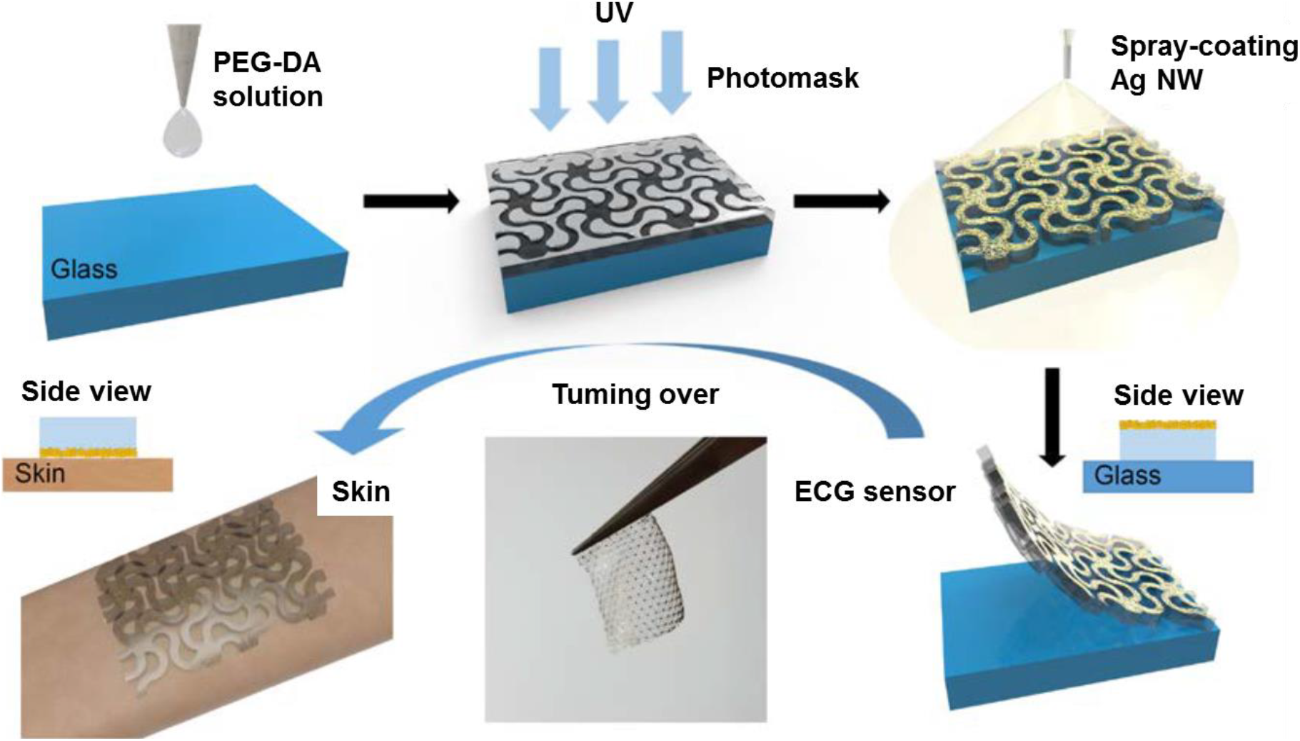
Fig. 12.: A schematic illustration depicts the process of fabricating hygroscopic auxetic electrodes. Reproduced with permission.[104] Copyright 2018, American Chemical Society.
Auxetic PU sponges were created from commercially available polyurethane sponges through triaxial thermal compression techniques, introducing buckled structures. Additionally, Ag nanowires were coated onto the resulting auxetic buckled scaffolds using a dip-coating method. The designed 3D auxetic conductors exhibited stable resistance under various modes of deformation, demonstrating their suitability for multimodal applications.[61] Highly stretchable conductors were fabricated by incorporating a hierarchical pattern into composite films composed of silver (Ag) flakes and a PDMS matrix (Fig. 13).[63] These developed conductors have the potential for applications in the field of foldable and stretchable electronics.

Fig. 13.: A schematic illustration showcases the process of fabricating a hierarchical patterned conductor using a highly conductive composite paste. Reproduced with permission.[63] Copyright 2020, Royal Society of Chemistry.
Aerogels of polyurethane with a re-entrant honeycomb pattern were manufactured to exhibit auxetic properties and enhanced flexibility compared to conventional aerogel monoliths (Fig. 14).[105] The fabrication process involved the utilisation of hollow molds with a re-entrant honeycomb shape, created using High-Impact Polystyrene (HIPS) through the 3D printing method. Subsequently, the polyurethane sol was added to the mold and washed with acetone to achieve the desired auxetic aerogel.
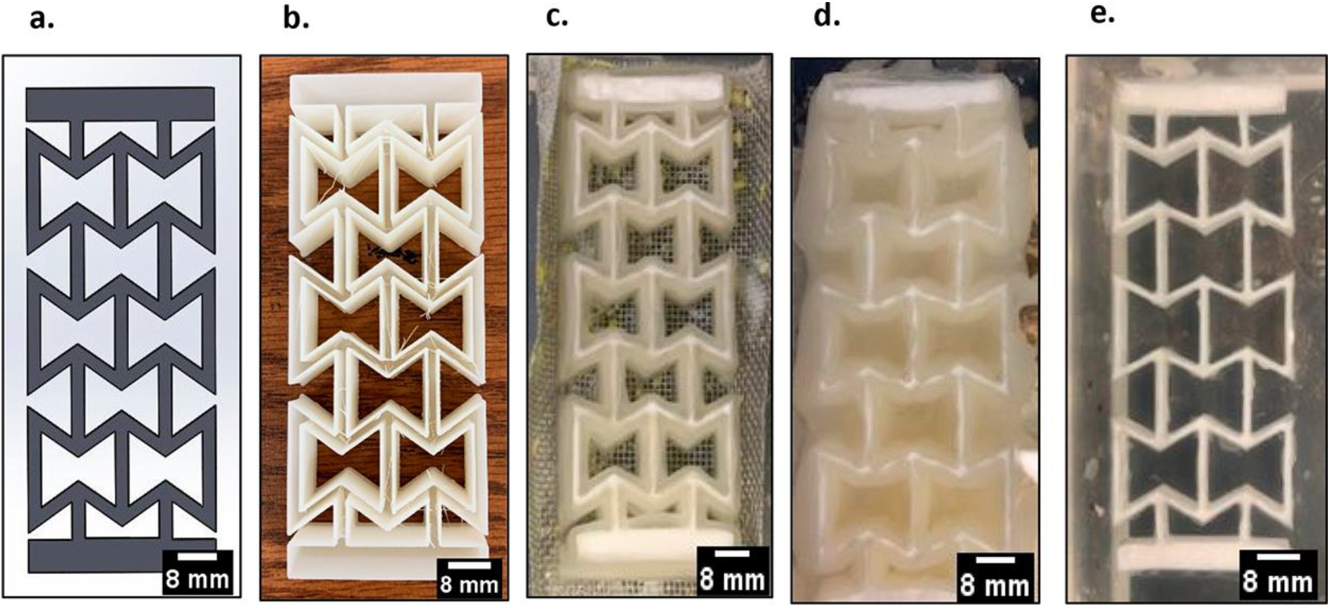
Fig. 14.: (a) Solid works model, (b) a hollow sacrificial mold, (c) polyurethane gel placed inside the mold, (d) the HIPS mold disintegrating in acetone, and (e) the resulting auxetic polyurethane gel. Reproduced with permission.[105] Copyright 2021, American Chemical Society.
Auxetic structures were achieved at a molecular level by integrating laterally attached rods, specifically terphenyl units, into the primary polymer chain.[85] These rods lie parallel to the chain before stretching, but when a tensile force is applied, they shift to a normal position with respect to the tensile axis, as depicted in Fig. 15. A subsequent development involved the creation of another auxetic polymer by substituting terphenyl rods with para-quaterphenyl rods. These rods had the ability to rotate up to 75° in relation to the polymer main chain, causing adjacent chains to separate when fully stretched (Fig. 9).[86]

Fig. 15.: (a) Before stretching, transverse rod lie parallel in the main polymer chain. (b) After stretching, rods change their alignment from parallel to normal with respect to tensile axis (resulting auxetic behaviour).
In 2018, an acrylate liquid crystal elastomer (LCE) was developed based on 6-(4-cyano-biphenyl-4'-yloxy)hexyl acrylate (A6OCB). Additionally, 2-Ethylhexyl Acrylate (EHA) monomer was included to enhance polymer backbone flexibility (Fig. 16).[106] The resulting LCE demonstrated semi-soft elasticity, exhibited "mechanical-Fréedericksz transitions," and displayed a negative order parameter. The research group also observed molecular auxeticity in the LCE, with the elastomer becoming auxetic for strains exceeding approximately 0.8 when the liquid crystal device is subjected to a force in a perpendicular direction. The study reported a maximum Poisson's ratio of -0.74 ± 0.03, which surpassed the values typically observed in naturally occurring molecular auxetics.[107]
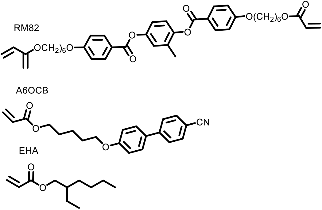
Fig. 16.: Chemical structure of RM82, A6OCB, and EHA.
3.5 One-Pot CO2 Foaming Process
A groundbreaking approach has been proposed to directly produce foam with a negative auxetic characterstics from polymer resin.[108] The method capitalises on the combined effects of water's phase transition and the dissimilar permeability rates between CO2 and air during the foam formation process. By utilising this technique, auxetic nylon elastomer (NE) foam is effectively synthesised from NE resin. The resulting auxetic foam has a Poisson's ratio of -1.29 and exhibited exceptional stability in tensile cycles, as well as outstanding energy absorption performance.
3.6 Centripetal freeze-casting
By employing a centripetal freezing technique, auxetic graphene metamaterials were effectively synthesised[109] This pioneering method entailed the growth of ice crystals towards the central region of an aqueous graphene dispersion, forming a skeleton arranged in a radial pattern. As the ice crystals sublimated, a re-entrant structure emerged diagonally within the monolith (Fig. 17). The resultant Centripetal Graphene Metamaterial (CGM) demonstrated a prominent and discernible auxetic behaviour.
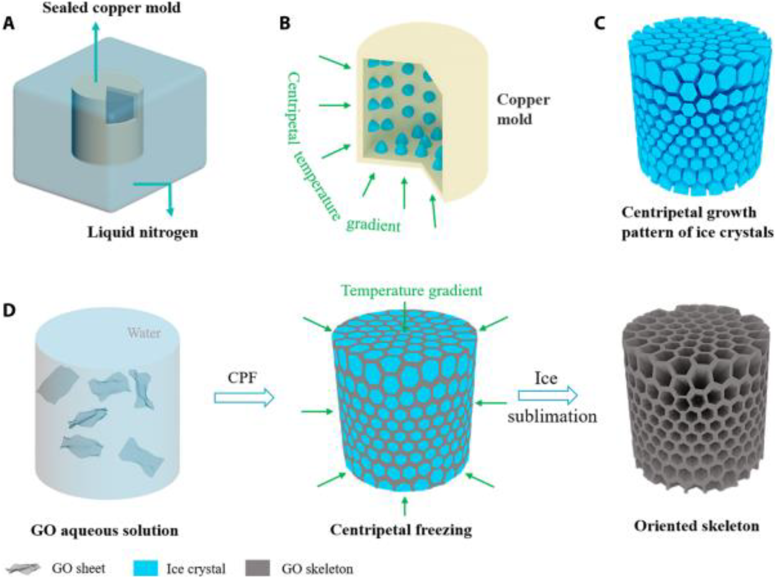
Fig. 17.: An illustration depicts the fabrication process of a graphene metamaterial. (A) A sealed copper mold, containing GO solution. (B) The copper mold induces a centripetal temperature gradient. (C) The model showcases ice crystals growth in radial directions. (D) A schematic representation of the fabrication procedure is provided. Reproduced with permission.[109] Copyright 2022, American Association for the Advancement of Science.
Numerous theoretical investigations and practical trials have been conducted to develop auxetic composite materials by utilising fiber-reinforced laminates and highly anisotropic substances.[110, 111] El Dessouky and McHugh carried out experiments in which they employed various weave designs to create intricate honeycomb structures, aiming to demonstrate the achievable auxetic properties in composite constructions.[112] The resulting composites displayed a Poisson's ratio of -2.86 and -0.12 during tensile and compression tests, respectively. In 2017, Jiang and Li utilised 3D printing techniques to develop a chiral auxetic composite material with a specifically designed cellular structure.[113] Additionally, a recent report in 2023 highlighted the development of an auxetic polyurethane foam/CNT composite foam for electromagnetic interference shielding effectiveness (EMI SE) applications.[34] The manufacturing process involved the preparation of a low-density polyurethane (LPU)/CNT composite foam through a solution dip-coating method. Subsequently, the LPU/CNT composite foam was transformed into an auxetic PU/CNT foam via a triaxial volumetric compression process (Fig. 18).
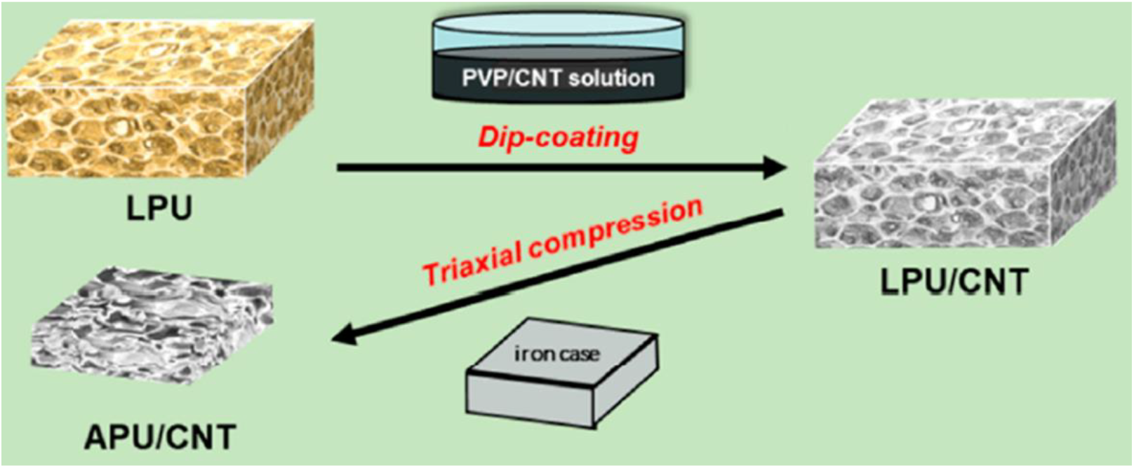
Fig. 18.: The process of fabricating APU/CNT foams involves the utilization of a dip-coating technique and a triaxial compression method. Reproduced with permission.[34] Copyright 2023, American Chemical Society.
The elastic indentation performance of auxetic UHMWPE was examined by Alderson et al.[114] The production of auxetic UHMWPE involved a carefully designed processing rig, encompassing compaction, sintering, and extrusion stages. These sequential steps ensured the development of an auxetic polymer with the desired structural properties, resulting in a continuous extrudate displaying distinctive cup-and-cone fractures at the ends.
Traditionally, the fabrication of synthetic auxetic materials involves compaction, sintering, and extrusion procedures. However, in 2005, Alderson et al. introduced a modified method that eliminates the need for extrusion, achieving the desired microstructure through compaction and multiple sintering stages.[115] The study focuses on investigating the effects of different sintering approaches on compacted cylinders. Strain-dependent Poisson's ratios as low as -0.32 were achieved by compacting the material and subsequently subjecting it to double sintering. This innovative method shows promising prospects for broadening the scope of fabricable structures and shares similarities with ceramic sintering techniques, highlighting its versatility and practicality.
4 AUXETIC MATERIALS PROPERTIES
Auxetic materials exhibit unique properties, for instance a negative value of Poisson's ratio, superior resistance to indentation, enhanced fracture strength, high shear resistance properties, and improved energy absorption capacity, which renders them appealing for diverse engineering and biomedical applications. These materials also have the ability to undergo large deformations without failure, making them useful for applications requiring flexibility and durability. Additionally, their variable permeability properties make them suitable for use in smart filters and other filtration applications.
Auxetic materials exhibit superior resistance to indentation compared to traditional polymeric materials. Equation 4 describes the interrelationship between the indentation resistance (H) and Poisson's ratio (υ). As υ approaches -1, H increases infinitely.[5] Fig. 19 visually demonstrates the contrasting effects of indentation on auxetic and non-auxetic materials. Unlike non-auxetic materials that shift laterally to alleviate pressure, auxetic materials contract and flow laterally towards the applied force. This behaviour results in the formation of a denser region, enhancing their ability to withstand indentation. Based on cylindrical and spherical elastic indentation tests, it was discovered that honeycomb cellular structures display a high level of indentation resistance.[116]
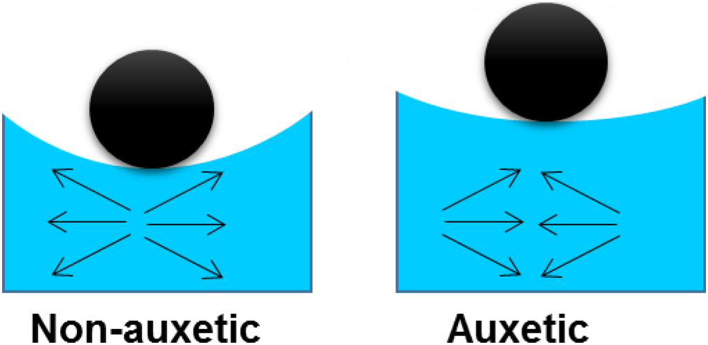
Fig. 19.: Impact of indentation on (A) non-auxetic materials; (B) auxetic materials.
To overcome the limitations of auxetic materials, 3D-printed auxetic composite materials were developed, utilizing auxetic structures as reinforcement in soft materials.[117] Auxetic composites exhibited enhanced impact and indentation resistance compared to non-auxetic composites. Furthermore, chiral truss and re-entrant honeycomb structures demonstrated improved mechanical performance when compared to regular truss and regular honeycomb structures.
In 1996, an experiment was conducted to determine the fracture strength of auxetic foam. This investigation revealed that auxetic foam exhibited significantly higher fracture strength in comparison to traditional foam.[118] The enhancement in fracture strength varied between 80% and 160% for volumetric compression ratios of 2.0, 2.5, and 3.0, respectively. Equation 5 can be utilised to assess and compare the fracture strength of auxetic foams and conventional foams.
In 2009, Donoghue et al. conducted a study investigating the fracture strength of carbon fiber laminates[119]. They performed a comparative analysis on laminates with similar moduli but different Poisson's ratios. The conclusion drawn from their research was that auxetic laminates demonstrated superior fracture toughness when compared to non-auxetic laminates.
Where Klc for fracture strength,
Synclastic behaviour refers to the capability of a material to adopt a curved, dome-like shape when subjected to a bending force perpendicular to its surface. Typically, conventional materials assume a saddle-shaped structure under bending conditions[46]. In contrast, auxetic materials exhibit a domed-shaped curvature. Naboni and Mirante demonstrated through empirical testing that auxetic materials display synclastic curvatures when pressure is exerted on their concave surfaces, opposing forces applied in the parallel direction.[120]
Experimental evidence has confirmed the superior energy absorption characteristics of auxetic materials compared to traditional materials.[121] Additionally, it has been observed that auxetic materials with a re-entrant unit outperform traditional honeycomb structures in terms of energy absorption during impact and close-in blast tests.[122] A comparative analysis was conducted to evaluate the energy absorption capabilities of auxetic re-entrant structures and conventional honeycomb structures[100]. The results indicated that re-entrant auxetic structures exhibited superior energy absorption performance compared to conventional non-auxetic structures. Najaf et al. examined the energy-absorbing capacities of three auxetic geometries (arrowhead, anti-tetra chiral, and re-entrant) under quasi-static loading and low-velocity impact conditions.[123] The re-entrant geometries demonstrated better performance during low-velocity impact loading, while the arrowhead and anti-tetra chiral geometries exhibited superior properties compared to the re-entrant geometries during quasi-static loading.
Several researchers have experimentally verified the unique property of variable permeability in auxetic materials,[124, 125] leading to their application in smart filters. In 2000, an experiment was conducted to create polymeric membranes based on micromachined re-entrant honeycomb and conventional honeycomb structures, evaluating their defouling properties and size-selectivity[126]. The study revealed that auxetic membranes exhibit superior size-selectivity and defouling properties compared to traditional membranes, making them crucial for smart filter applications. In another study, a comparison was made on the porosity and auxeticity of systems created using rotating rigid units such as rotating rectangles, squares, rhombi, and parallelograms.[127] The findings suggested that pore size and space coverage can be regulated depending on factors such as unit connectivity, unit shape, and the angle between the units.
From Equation 2, as the absolute value of the Poisson ratio approaches -1, the shear resistance increases. Therefore, as υ→ -1, G →∞. The shear resistance properties of re-entrant honeycomb[128, 129] and chiral lattice[130] have been extensively investigated in the literature. The shear moduli of conventional foam and auxetic foam were measured and compared to the calculated value using elastic theory for isotropic materials.[131] The measured shear moduli values for conventional foam and auxetic foam were 32±8 kPa and 16±7 kPa, respectively. Moreover, a comparative study of the calculated and measured shear moduli values suggested the applicability of the elastic theory in determining the shear moduli of isotropic foam.
5 CHARACTERISATION OF AUXETIC PROPERTY EVALUATION
Characterising auxetic materials is an essential aspect of comprehending their unique mechanical behaviour. One of the most commonly used methods for characterization is measuring the Poisson's ratio, which quantifies the material's deformation behaviour under stress. Other methods encompass microstructural analysis and mechanical testing. By combining these techniques, researchers can gain insights into the underlying mechanisms that give rise to auxetic behaviour, as well as understand the material's mechanical properties under different loading conditions. Understanding the characteristics of auxetic materials is crucial for their potential applications in areas such as protective clothing, sports equipment, and biomedical devices.
In literature, various approaches for characterizing polymeric materials are explored, including techniques such as differential scanning calorimetry (DSC), thermogravimetric analysis (TGA), Fourier-transform infrared spectroscopy (FTIR) analysis, and proton nuclear magnetic resonance spectroscopy (NMR). However, the focus here lies on the specific characterization techniques employed for auxetic polymeric materials.
Density measurements of auxetic materials are important to determine their weight and packing density. The density of auxetic materials can be affected by their unique structure and geometry, which can be different from conventional materials. Therefore, accurate density measurements are crucial for understanding the physical and mechanical properties of auxetic materials. Chen et al. calculated the density of foam (ρf) using equation 6.[132]
Where, Wf denotes weight of foam and Vf geometric volume of foam.
Further, porosity (P) was calculated using equation 7.
Where, ρf, ρa, and ρl stands for density of foam, air (1.225 kg/m3), and LDPE (low density polyethylene, 918 kg/m3).
The polyethylene occupied volume (Vl) was calculated using equation 8.
Where, Vf stands for foam occupied volume.
In a study conducted by Vinay et al.,[133] the apparent density of conventional foam and auxetic foam was measured at room temperature. Formula 6 was utilised to calculate the density. The results indicated that the apparent density of auxetic foam (69.39 ± 1.06) was higher compared to conventional foam (38.02 ± 0.93).
Tensile testing is a commonly used method to assess the mechanical characteristics of materials, including factors such as durability and flexibility. Various types of testing machines, such as universal testing machines, hydraulic testing machines, and servo-hydraulic testing machines, can be employed for tensile testing.[103]
Li et al. conducted an experiment to determine the Poisson's ratio of foam using a universal testing machine.[134] A rectangular section from the center of the foam sample was selected, and three lines were marked on it perpendicular to the direction of tension. Subsequently, the sample was stretched at a predetermined rate, and measurements of length and width were taken at intervals of 10% of the engineering strain until it reached 100%. The longitudinal and transverse strains were calculated using formulas 9 and 10, respectively, and equation 1 was utilised to calculate the Poisson's ratio.
The study examined the auxetic effect of both conventional foam (SNP-PU) and auxetic foam (A-SNP-PU) at approximately a 5-mm displacement[133]. The findings revealed that as the displacement increases, there is a gradual reduction in the auxetic effect (Fig. 20).
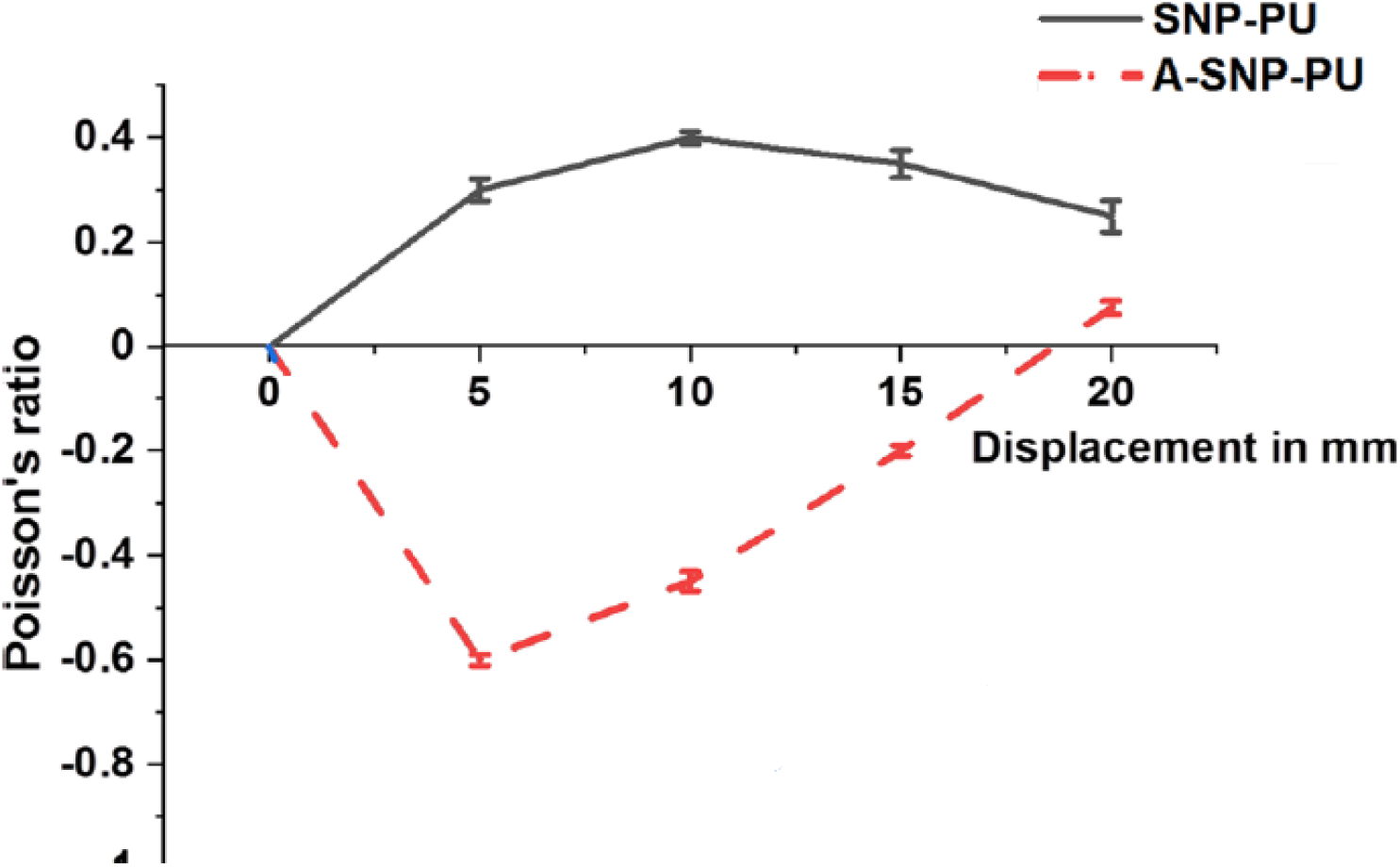
Fig. 20.: The graph displays the relationship between displacement and Poisson's ratio, with the red line representing the auxetic foam and the black line representing the conventional foam. Reproduced with permission.[133] Copyright 2022, Springer.
For the evaluation of chiral auxetic cellular structures under quasi-static loading conditions, a servo-hydraulic testing machine was employed. The testing procedure involved using a position-controlled cross-head rate of 0.05 mm/s during the tensile testing process.[135] To assess the deformation behaviour and determine the Poisson's ratio in the tested structures under loading, GOM Correlate software was utilised. This software utilised Digital Image Correlation (DIC) and tracking techniques. Throughout the loading process, the axial and lateral deformations of the specimens were consistently monitored, starting from the initiation of the loading sequence until their ultimate failure. The results indicated that both structures exhibited similar initial stiffness, but the hexachiral structure displayed a more ductile response with a failure strain over four times greater in magnitude compared to that of the tetrachiral structure.
The mechanical properties of Double Arrow Head (DAH) auxetic materials were evaluated through a tensile test.[136] The study revealed that when subjected to uniaxial force, regardless of the force direction, the DAH structure initially extended perpendicular to the force and then underwent contraction. Furthermore, the study demonstrated that the DAH structure exhibited a greater auxetic effect when subjected to tensile forces in the X direction compared to the Y direction. Notably, the study found that smaller angles resulted in a more pronounced auxetic effect.
Compression testing is a mechanical technique used to assess the compressive strength and other mechanical characteristics of materials. Various testing machines, including universal testing machines, hydraulic testing machines, and servo-hydraulic testing machines, can be employed for compression testing.[135, 136]
Vinay et al. conducted mechanical compression tests on both conventional foam and auxetic foam cubes at room temperature, resulting in stress-strain curves[133]. The obtained stress-strain curves were analyzed, revealing that the conventional foam exhibited an initial linear stress-strain correlation, followed by a region of stability and densification. In contrast, the auxetic foam exhibited higher stiffness and lacked plateau regions in its stress-strain behaviour.
Static tests were conducted to evaluate the mechanical strength of the foam, involving three successive compressions to 30% deformation, followed by a single compression up to 80%.[137] The results demonstrated that the auxetic foam displayed a significant hysteresis loop, indicating superior energy dissipation capacity. The physical characteristics of the auxetic foam were found to be superior to those of non-auxetic foams used in public and aviation transport. Based on these findings, the researchers concluded that the processed auxetic foam holds promise for various industrial applications that require excellent energy dissipation and mechanical properties.
Indentation testing is a mechanical method used to determine various mechanical properties of a material, including hardness and elastic modulus. This testing involves applying a known force to a small area of the material's surface using a pointed or spherical indenter and measuring the resulting deformation or penetration. Typically, the specimen used in indentation testing has a flat surface, and the indenter can be made of different materials such as diamond, steel, or tungsten carbide. The force is usually applied using a testing machine, such as a universal testing machine or a specialized indentation testing machine. The deformation or penetration depth is then measured using a microscope or a displacement sensor, and these measurements are used to calculate the material's mechanical properties[138].
Li et al. conducted indentation experiments using a cylindrical indenter with a radius of 20 mm and an MTS mechanical tester[117]. The tests were performed under quasi-static conditions, with an indenter velocity of 0.05 mm/s, resulting in a nominal engineering strain rate of 0.00167/s. During the tests, a high-speed imaging camera (Photron SA1.1) was employed to capture images of the specimens subjected to various loading conditions. The investigation demonstrated that the presence of auxetic reinforcement led to increased indentation stiffness of the composites compared to composites reinforced with non-auxetic materials.
Impact testing is a mechanical procedure used to assess a material's ability to absorb energy and withstand fracture under dynamic loading conditions. This test involves subjecting a sample to a sudden impact or shock by striking it with a pendulum, falling weight, or projectile.
To explore the potential advantages of incorporating auxetic foams as cushions in helicopter seats, drop tests were conducted.[137] The testing apparatus utilised in these tests consisted of a hammer and an anvil, with the hammer instrumented with an accelerometer and the test stand fitted with a photo-optical sensor to measure velocity. The experiments were conducted using a variety of hammer weights, ranging from 99.5 N to 204.8 N. The study revealed that the auxetic foam, exhibited higher maximum deceleration values compared to the conventional foam. However, the conventional foam demonstrated a more elastic response.
In another study, an impact test was performed on auxetic-reinforced composites[117]. An impactor with a mass of 335.26g and a radius of 5mm was used to measure and record the impact velocity and force, thereby assessing the behaviour of the tested materials under impact loading conditions. The findings revealed that auxetic-reinforced composites exhibited superior resistance to impact when compared to composites without auxetic reinforcement.
Shear testing is a mechanical technique used to determine the modulus and strength of a material by applying a perpendicular force that induces deformation or shearing. The required force to cause deformation is measured to calculate the shear strength and modulus. Navok and colleagues conducted shear tests on both conventional and auxetic materials[131]. The foam samples were affixed to two rigid parallel plates using epoxy resin and tested in three orthogonal directions. As the linear displacement of the shear plates increased, the testing apparatus subjected the specimen to both shear deformation and axial tension (Fig. 21). The measured shear moduli were then compared with the calculated shear moduli obtained from compression tests using an equation.

Fig. 21.: Illustrates the deformation behaviour of both (a) conventional and (b) auxetic foam samples subjected to shear loading at different stages of deformation, i.e., 0%, ∼40%, and ∼80% applied shear, from left to right, respectively. Reproduced with permission.[131] Copyright 2021, Elsevier.
If the open-cell foam is isotropic, the researchers suggested that the low-strain shear modulus could be determined using elasticity theory by incorporating the Young's modulus and Poisson's ratio obtained from compression tests.
5.7 Morphological characterization
Characterizing the morphology of auxetic materials is crucial for understanding their properties and behaviour. These materials possess the unique ability to expand laterally when stretched. To examine the microstructure and morphology of these materials at various length scales, researchers often utilise transmission electron microscopy (TEM) and scanning electron microscopy (SEM) techniques. These techniques allow researchers to visualize the cell and void structures responsible for the auxetic behaviour and study the material's composition, crystallography, and defects.
SEM images taken at various temperatures revealed distinct closed-cell structures with large isolated cells surrounded by smaller cells.[134] The insights gained from these observations offer valuable information about the morphology of auxetic materials, highlighting the critical role of microstructure in shaping their mechanical properties.
The morphological characterization of 3D printed hydrogels, as presented in the study, demonstrated significant structural differences based on the choice of cross-linking agents (Fig. 22).[103] The inclusion of triethylene glycol dimethacrylate (TEGDMA) as a cross-linking group resulted in a continuous network of poly(2-hydroxyethyl methacrylate) (pHEMA), while cross-linking agents based on cellulose nanocrystals (CNC) produced a dense and regularly spherical porous structure. Additionally, the analysis of pore size distribution revealed that the methacrylated cellulose nanocrystals (CNCMA) cross-linking agent resulted in a narrower distribution of pore sizes compared to the unmodified CNC cross-linking agent. Moreover, the concentration of CNCMA significantly influenced the hydrogel's morphology. These findings provide valuable insights into the role of cross-linking agents in controlling the microstructure of hydrogels and suggest novel strategies for designing and optimising hydrogel materials for diverse applications.
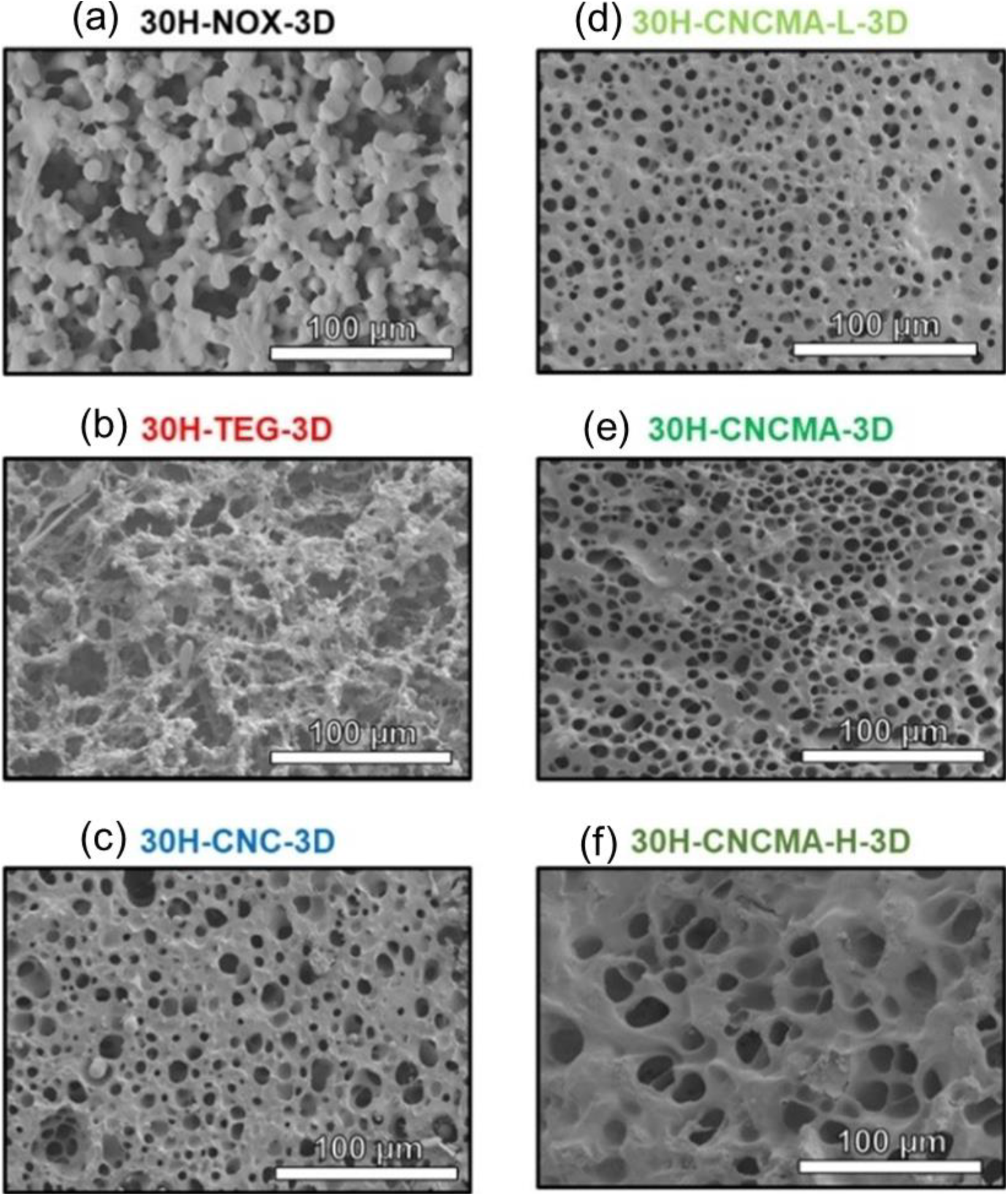
Fig. 22.: The fig. illustrates the morphology of several hydrogels fabricated through 3D printing. In Part (a), a scanning electron microscopy (SEM) image showcases the hydrogels with varying cross-linking agents: (a) absence of a cross-linking agent, (b) TEGDMA (0.8), (c) CNC (0.8), (d) CNCMA (0.4), (e) CNCMA (0.8), and (f) CNCMA (1.6). Part (b) of the fig. presents the pore size distributions of CNC/CNCMA hydrogels, each containing different concentrations of the cross-linking agent. Reproduced with permission.[103] Copyright 2022, Wiley VCH.
Xu and colleagues conducted an investigation into the structural morphology of auxetic foam composites using FE-SEM observation.[34] Through their analysis of two types of composites, namely low-density polyurethane/carbon nanotube (LPU/CNT) and auxetic polyurethane/carbon nanotube (APU/CNT) foams, they discovered distinctive morphological characteristics that contribute to the unique properties of these materials. In the LPU/CNT foam, SEM imaging revealed a dense distribution of noodle-like interlinked CNTs on the foam's framework, creating compact conductive networks internally. On the other hand, the APU/CNT foam exhibited re-entrant geometries resulting from triaxial compression-induced 3D shrinkage. This structure differs significantly from the conventional spherical microcellular pattern typically found in non-auxetic foams (Fig. 23a,b).
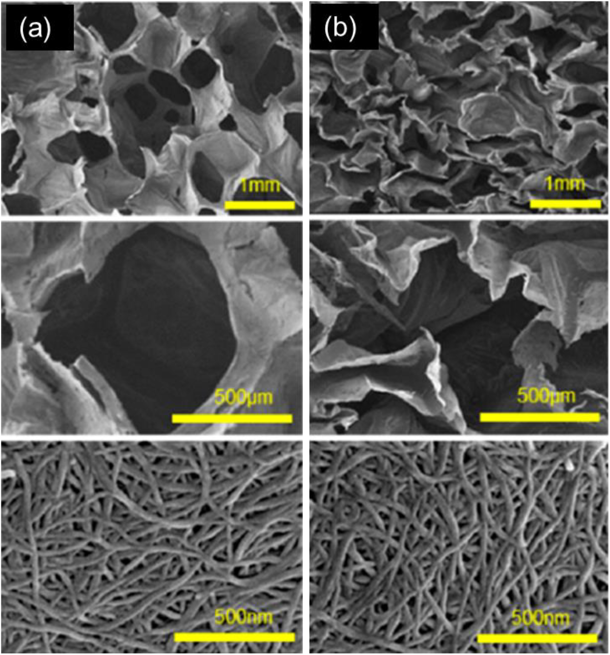
Fig. 23.: SEM images of the (c) LPU/CNT and (d) APU/CNT foams at different magnifications. Reproduced with permission.[34] Copyright 2023, American Chemical Society.
6.1 Impact/Ballistic Applications
Auxetic polymers have shown great potential for use in impact and ballistic applications due to their distinctive mechanical properties. In addition to their mechanical attributes, auxetic polymers offer other benefits for impact and ballistic applications. For example, they are lightweight, flexible, and can be tailoured to specific needs. This makes them an attractive option for use in sports equipment and military gear, where mobility and comfort are essential.[139] Through a range of experiments and simulations, researchers have effectively demonstrated the advantages of auxetic polymers in impact and ballistic applications. One study revealed that incorporating ribs into a re-entrant cell structure led to improved energy absorption and strength of the material.[140] The modified structure exhibited increased resistance to deformation and the ability to handle higher loads due to enhanced stiffness and strength properties. Another investigation by Jiang and Hu discovered that both conventional and auxetic composites were sensitive to strain rate. However, within the medium strain range, the auxetic composite demonstrated enhanced energy absorption capabilities.[141]
To mitigate the detrimental consequences of high-velocity lateral impacts, such as those from vehicular collisions, a method was proposed for designing and incorporating structurally altered auxetic foam within the hollow cores of block masonry walls.[142] Structurally altered auxetic foams were created by placing acrylonitrile butadiene styrene (ABS) tubes and polyester sheets of different geometries into conventional PU foams. The developed auxetic foam exhibited Poisson ratio of -12. Analytical validation and subsequent modeling of masonry walls containing auxetic foam insertions demonstrated a significant reduction in displacement and a change in the failure mechanism during high-velocity lateral impact analysis. This resulted in safer masonry buildings situated along busy road fronts.
Studies have also indicated that auxetic panels outperform conventional panels under impulse loadings such as blast loadings. A numerical study examined the behaviour of auxetic composites when subjected to blast loading, revealing enhanced energy dissipation and decreased displacement.[143]
6.2 Acoustic and structural applications
Porous materials have become widely employed in the fields of energy absorption and sound reduction across a wide range of frequencies due to their impressive capabilities in energy dissipation and sound absorption. However, their mechanical limitations have hindered their use in shock-absorbing materials. To address this, a novel approach involving non-solvent induced phase separation was employed to produce auxetic foam featuring a meticulously structured honeycomb concave micropattern on its surface. This development has significantly enhanced the foam's capacity to dissipate shock energy.[144]
Another study aimed to investigate the effectiveness of polyurethane foams with multi-auxetic properties as efficient absorbers of acoustic waves.[145] The research focused on exploring the influence of auxeticity on the sound wave absorption performance of the prepared foams. Several samples were analysed, featuring compression ratios ranging from 0% to 50%, in order to determine their sound absorption characteristics.
The findings of the study revealed that when sound waves first encountered a region characterised by a higher compression ratio, a marginal enhancement in sound absorption performance was observed specifically within the low-frequency range. This improvement was attributed to the buckled open-cell microstructure's small pores, which facilitated multi-scattering when sound waves of low frequency entered. On the other hand, when the sound wave initially entered a region characterised by a lower compression ratio, there was a tendency for the sound absorption performance to improve particularly within the high-frequency range. This was because the larger pores in that region allowed easier entry of the shorter wavelengths associated with high-frequency sound.
Auxetic polymers offer significant advantages in automotive applications where energy absorption and impact resistance are critical. Their utilisation in the automotive industry primarily focuses on designing crash-resistant materials for car bodies and safety equipment, such as airbags. The unique property of auxetic polymers allows for more efficient energy absorption and even dispersion of impact forces, thereby reducing the risk of passenger injuries in the event of a collision. Moreover, these polymers find application in the development of high-performance tires, enhancing grip, traction, and stability on the road. The exceptional stretching and expansion characteristics of auxetic polymers contribute to improved tire grip during braking and acceleration, enhancing safety and reliability.[146]
In a particular study, a graded cellular structure with auxetic properties was designed and modeled for potential utilisation in a crash box application.[147] The optimised structure exhibited superior energy absorption capabilities and lower reaction forces compared to a uniform cell design. Rigorous collision tests were conducted, and the graded auxetic structure successfully passed them, thus demonstrating its effectiveness in this specific application.
Shape memory polymers (SMPs) belong to a category of materials capable of undergoing shape alterations in response to external stimuli, including light, heat, or magnetic fields. The integration of shape memory and auxetic properties has resulted in the development of Shape Memory Auxetic Polymers (SMAPs), which have garnered significant interest for various engineering applications. While most SMPs exhibit responsiveness to temperature fluctuations, there have also been advancements in the development of light-responsive SMPs.[148]
Rossiter et al. presented a novel shape memory polymer with auxetic properties, wherein the stiffness response could be adjusted by modifying the angle of inter-hub connections. This innovative design retained its thermally stimulated deployment capability, showcasing the potential of shape memory auxetic polymers.[149]
Fan et al. achieved a significant advancement by creating an auxetic foam that demonstrates the remarkable capability to expand or contract, depending on the ambient temperature, in response to the vaporisation or condensation of water, respectively.[150] Leveraging this behaviour, shape memory materials were produced using the auxetic foam. A bilayer specimen was constructed by bonding PE auxetic foam to a polyurethane film. Submerging the bilayer in hot water caused the PE auxetic foam layer to undergo significant swelling, resulting in the specimen bending and forming a loop shape. Upon removal from the hot water, the bilayer specimen swiftly returned to its original shape, clearly demonstrating the shape memory properties of the developed auxetic foam (Fig. 24).
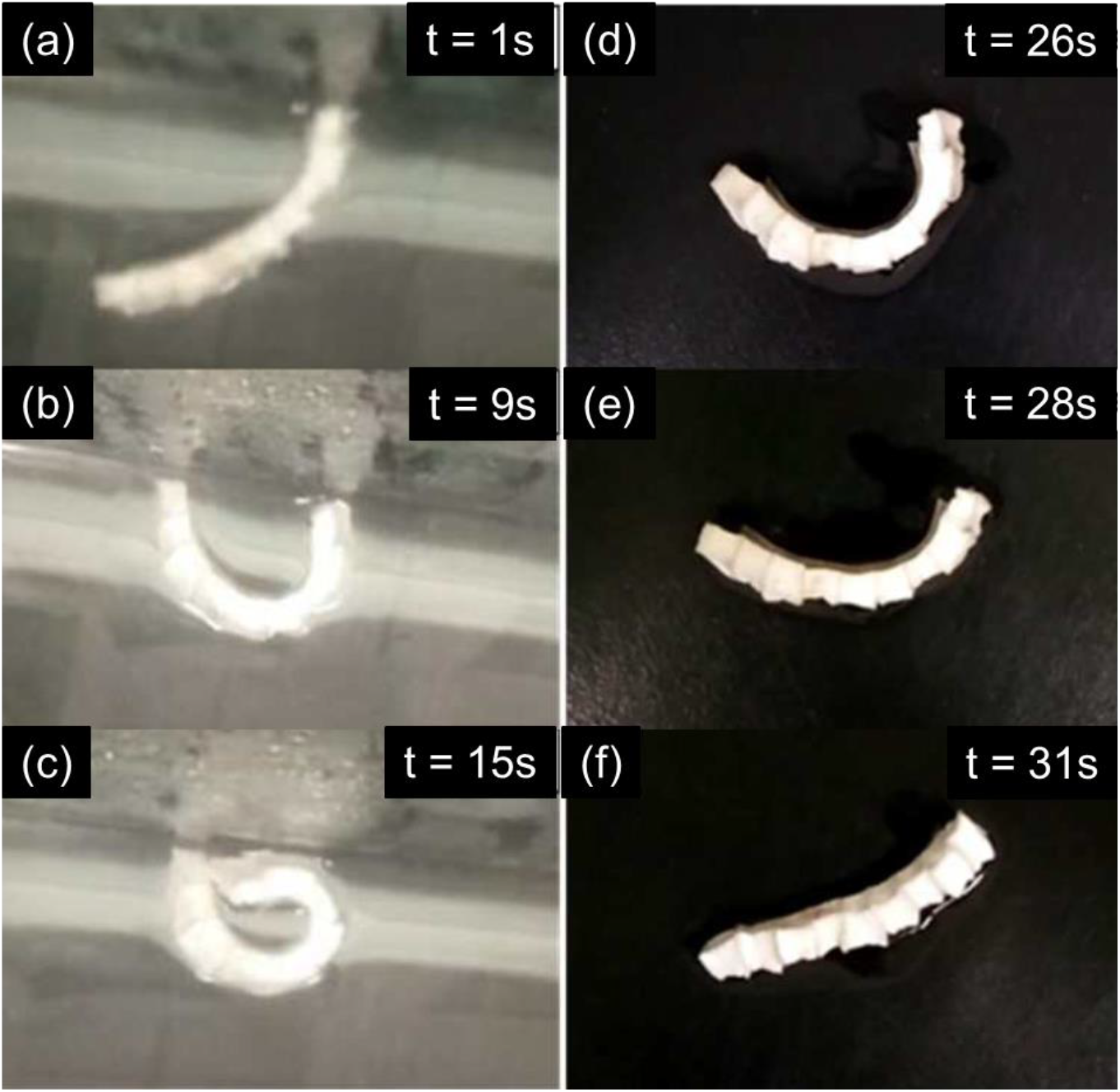
Fig. 24.: The shape memory characteristic of the bilayer sample. (a), (b), and (c), the sample was submerged in hot water with a temperature of 100°C. (d), (e), and (f), the sample was subsequently removed from the hot water and left to cool down to room temperature. Reproduced with permission.[150] Copyright 2018, American Chemical Society.
In a research study, a novel auxetic shape memory polymer based on 4D printing was developed, demonstrating captivating shape memory properties with high fixity values and nearly full recovery of its initial shape.[151] Notably, the material demonstrated a wide glass transition region, leading to a thermal memory effect (TME). The TME enabled the programming of self-deployment capabilities and hierarchical motions driven by temperature, encompassing intricate sequences of in-plane and out-of-plane motions. These findings suggest promising applications in soft robotics and biomedical components, where the integration of diverse motion and response types can be advantageous.
Auxetic polymers can be used as strain sensors that detect changes in mechanical deformation or elongation. These sensors can be integrated into smart materials, textiles, or medical devices for real-time monitoring of changes in the surrounding environment or for medical diagnostics.
Researchers have successfully developed an innovative self-powered strain sensor (Ax-TENG), specifically designed for detecting human body motion[152]. This sensor makes use of auxetic foam, which expands when stretched, generating electricity through contact with a friction layer. With an impressive strain sensitivity value of 1.6 V cm-2, the Ax-TENG can accurately detect various types of motion, including pressing, bending, and twisting. Its versatility allows for a wide range of applications, such as examining human body motions, weight sensing, and seat belt monitoring in cars. This pioneering utilisation of auxetic materials in self-powered sensing represents an exciting advancement in the field of wearable technology and smart materials, holding immense potential for future developments.
The emergence of 5G technology has brought attention to the issue of electromagnetic pollution and interference, which poses significant risks to both electronic devices and human well-being. Consequently, researchers are actively exploring and developing advanced materials to reduce the adverse effects of electromagnetic waves through electromagnetic interference (EMI) shielding [153, 154]. In this context, a combination of triaxial volumetric compression and solution dip-coating techniques was employed to manufacture lightweight composite foams comprising APU/CNT[34]. Comparatively, the APU/CNT foam exhibited more consistent shielding effectiveness (SE) values as the tensile strain increased, particularly within the initial 20% strain range, than PU/CNT foam. This enhancement in EMI shielding performance can be attributed to the inclusion of an auxetic material, which led to a slight increase in the foam's thickness and prevented severe damage to the conductive networks during stretching. As a result, the attenuation of electromagnetic waves became more stable. Moreover, the stretched APU/CNT foam demonstrated remarkable and consistently reliable Joule-heating performance.
The utilisation of auxetic materials in membrane barriers offers an effective solution for addressing cake fouling issues in real-time. These materials possess a passive pore variation mechanism, allowing the pressure drop across the barrier to increase as the cake foulant accumulates. As a result, the barrier bows, and its pores open up and counterbalance the decrease in pore size caused by fouling. This inherent mechanism extends the lifespan of the filter, which is not achievable with traditional membranes. Thus, the use of auxetic membranes in smart filters holds tremendous potential.
In a specific study, honeycomb membranes featuring both conventional and re-entrant cellular structures were developed by means of femtosecond laser ablation.[126] The primary deformation mechanism observed was the flexure of the honeycomb ribs. The researchers conducted experiments by subjecting the auxetic membrane to glass chromatography beads. When subjected to tensile loading, the membrane experienced deformation, resulting in the opening of auxetic cells that facilitated the passage of beads through the membrane (Fig. 25). This behaviour highlights the promising characteristics of auxetic materials for filter cleaning or defouling operations.

Fig. 25.: The defouling process of re-entrant membranes when subjected to glass chromatography beads. Fig. (a) shows an undeformed membrane with approximately 60% bead coverage. As the membrane is strained in the x direction, the bead coverage decreases to approximately 50% at a strain of 0.5% (fig. b), 40% at a strain of 0.75% (fig. c), and 30% at a strain of 1% (fig. d). Reproduced with permission.[126] Copyright 2000, American Chemical Society.
Attard et al. explored the auxetic materials in the development of intelligent filters with adjustable sieving properties.[155] Specifically, the researchers examined the auxetic materials that contain a rotating rigid unit. Mathematical expressions are derived to determine the space coverage. These expressions indicate that these systems provide a wide range of space coverage and, pore sizes which can be regulated by the connectivity of the units, their shape, and the angle between them.
6.8 Rehabilitation applications
Despite efforts to improve the comfort of wheelchair users using various materials, issues such as foam thinning and excessive sweating continue to persist. These problems can lead to inadequate stress distribution and potential skin infections. To address these challenges, researchers are exploring novel materials like auxetic foams for rehabilitation purposes. Auxetic foams are characterised by exceptional resistance to indentation, even pressure distribution, and significant shear stiffness, making them well-suited for wheelchair cushions. By providing improved pressure distribution and reducing the risk of skin infections, auxetic foams have the potential to significantly enhance the comfort and quality of life for wheelchair users.
In a recent study, the applicability of castor oil (CO)-based APU foams as seat cushions in wheelchairs was investigated.[156] The study demonstrated that the inclusion of castor oil enhanced both the mechanical properties and antibacterial activity of the foams. The foams exhibited superior storage modulus and compression strength, suggesting their promise as an excellent substitute for traditional PU foams in wheelchair seat cushions and applications within hospital beds. These findings suggest that CO-APU foams have the capability to improve the comfort and enhance the well-being of individuals who use wheelchairs or require extended periods of bed rest in healthcare settings.
Auxetic polymeric materials have emerged as promising candidates for biomedical applications due to their exceptional stability, favorable mechanical properties, and adaptable structures. These materials hold potential for use in tissue engineering and the development of biomedical devices such as sensors and stents.
Park and Kim conducted a study involving an auxetic PU scaffold to explore the impact of compressive stimulation on chondrocyte proliferation for cartilage regeneration.[157] The control sample exhibited Poisson ratio of 0.9 ± 0.25, while the experimental specimens exhibited Poisson ratio of -0.4 ± 0.12 (approx.). In cell proliferation tests, the auxetic PU exhibited a 1.3-fold increase in cellular proliferation rate compared to the control group. Furthermore, following five days of culture, the auxetic PU displayed an increase (1.5-fold) in collagen content compared to the control group. The presence of auxetic geometries in the framework likely played a role in the increased collagen content, as the negative value of Poisson's ratio facilitated the transmission of isotropic compressive loads to the cells.
In 2018, researchers focused on developing auxetic re-entrant cardiac patches for treating myocardial infarction, utilising chitosan-polyaniline films with adjustable mechanical properties.[158] The patches were fabricated using the laser sintering method and exhibited enhanced metabolic activity and cell proliferation compared to the control, both in the auxetic conductive cardiac patch (AuxCPs) and the unpatterned cardiac patches (UnpatCPs). Ex vivo testing involving whole rat hearts and ultrathin myocardial slices demonstrated that the AuxCPs displayed anisotropic electrical conductivity in both the parallel and perpendicular directions to the longitudinal axis of the cardiac tissue (Fig. 26). The stretched and contracted AuxCPs were capable of replicating the behaviour of native heart tissue, highlighting their potential application as promising biomaterials for cardiac tissue engineering.
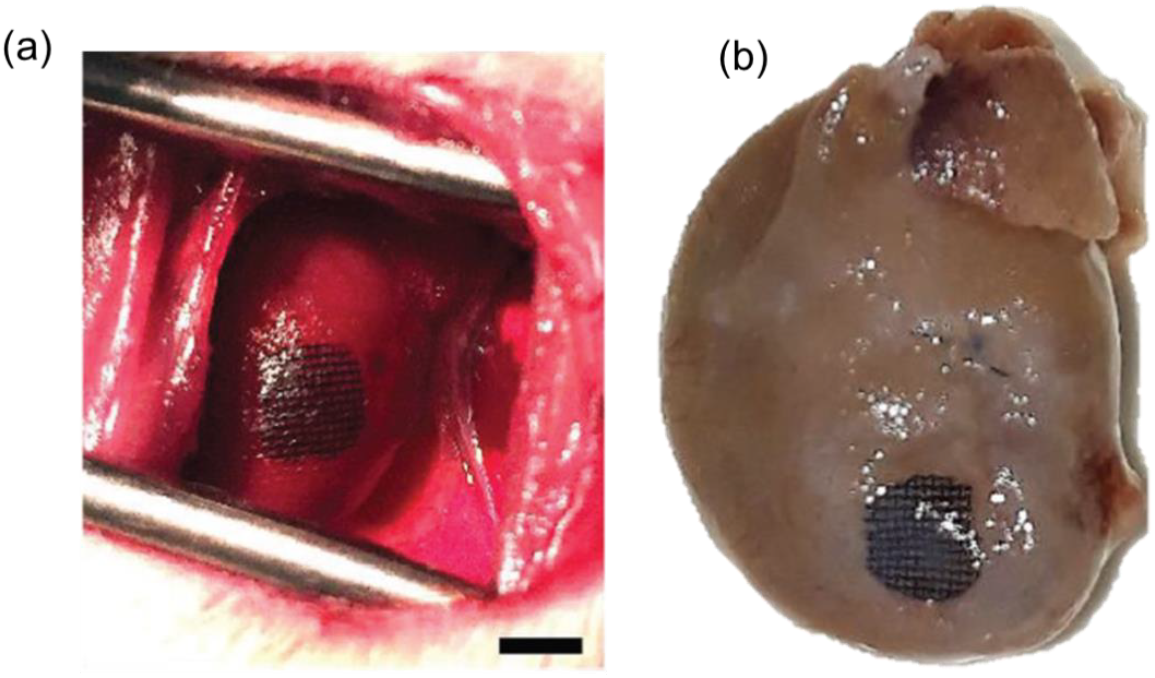
Fig. 26.: The left ventricle of a rat with an attached AuxCP is shown in the image, taken (a) on the day of the surgery and (b) 14 days after the surgery. Reproduced with permission.[158] Copyright 2018, Wiley VCH.
Stents are medical devices used for unblocking passageways in the body, such as blood vessels and the esophagus. They are inserted into the patient and expanded using a balloon catheter, causing the stent to undergo plastic deformation and secure its position. This procedure helps maintain the openness of the passageway and can lead to improved patient outcomes.[159]
In a successful research endeavor, a rotating-square esophageal stent composed of polyurethane films was developed. This unique stent exhibited a highly negative value of Poisson's ratio (υxy= -0.89 ± 0.01) and featured a dome-shaped surface when subjected to external uniaxial tensile loads.[160] The design of the stent aimed to provide effective expansion within the esophagus while ensuring a strong grip on tumor tissues, thereby preventing food blockage. In comparison to conventional non-auxetic stents (Fig. 27), the rotating-square esophageal stent demonstrated superior performance in preventing obstructions.
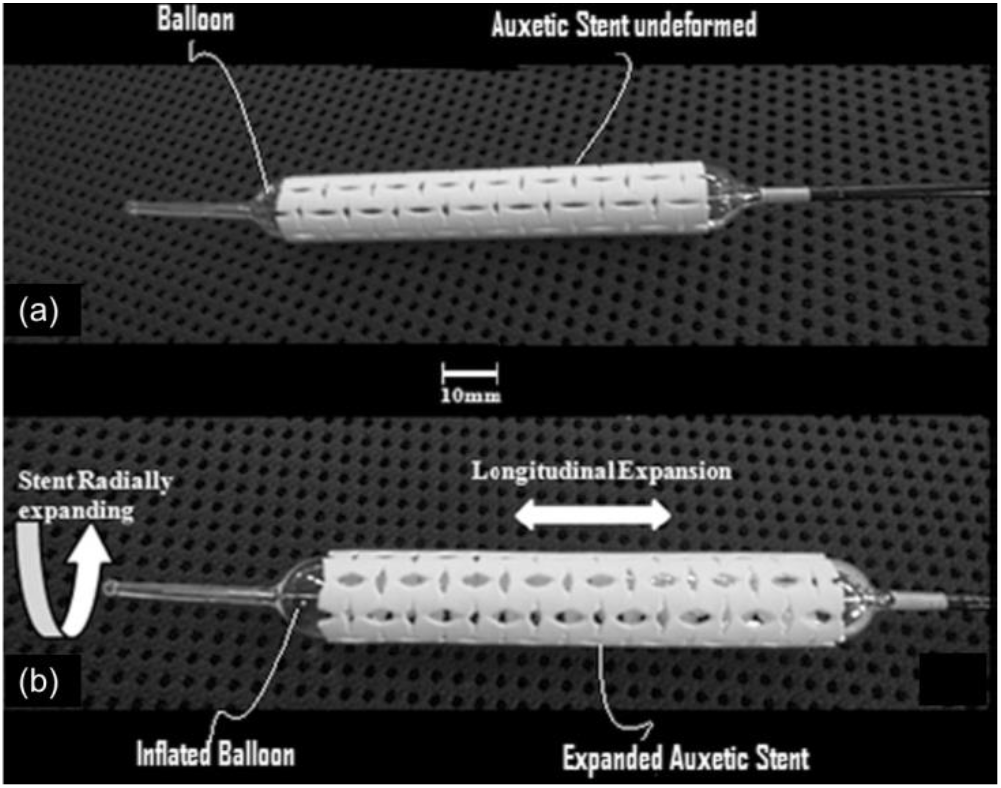
Fig. 27.: In fig. (a), the auxetic stent is attached to a balloon catheter, while in fig. (b), it is expanded both radially and longitudinally using the balloon catheter. Reproduced with permission.[160] Copyright 2014, Springer.
Comparative testing revealed that auxeticfibers exhibited enhanced resistance to fiber pull-out in comparison to conventional fibers.[9] This discovery could potentially lead to the development of stronger and more durable materials in various fields of application. Specifically, in the biomedical industry, the use of auxetic fibers could enhance the performance of surgical sutures or muscle ligament anchors, leading to better patient outcomes.[161]
Auxetic materials may find potential applications in sports equipment and clothing because of their synclastic curvature and superior performance in vibration damping and crushing.[152, 153] They may also have potential in safety devices for snow sports.[164, 165]. In addition, the potential of auxetic foam in reducing peak forces and resisting “bottoming out” under impact makes it well-suited for sports products.[166, 167]
To cater specifically to sports applications, a thermo-mechanical process was utilised to manufacture sheets of auxetic foam with through-thickness compression ratios of 0.6 and 0.7, and a lateral compression ratio of 0.8.[168] However, the converted foam exhibited slight in homogeneity, with lesser density at the interior compared to the corners.
Finite element simulations were presented for a novel cylindrical-ligament honeycomb structure that displayed auxetic behaviour.[169] This honeycomb structure, with synclastic curvature, holds promise as a potential core material for sports helmet applications. The double-curvature of the honeycomb allows it to conform to the helmet shape, while the cylinders provide optimal resistance against through-thickness crushing or impact events.
In a study aiming to enhance the conformable layer of sports helmets and reduce linear impact acceleration, open-cell polyurethane auxetic foams were investigated.[170] Helmets with both auxetic and conventional foams as the conformable layer were tested by dropping them with a head form in front and side orientations to examine the reduction of linear acceleration. The results indicated that helmets with auxetic foam showed diminished peak linear accelerations and the Gadd Severity Index compared to their conventional counterparts. This study emphasizes the impact of the conformable layer on the overall attenuation properties of helmets, suggesting that incorporating auxetic foam can potentially decrease the risk of brain injuries resulting from sport-specific collisions.
Furthermore, it has been demonstrated that auxetic foam surpasses conventional foam and offers functional advantages as personal protective equipment (PPE) in sports apparel.[171]
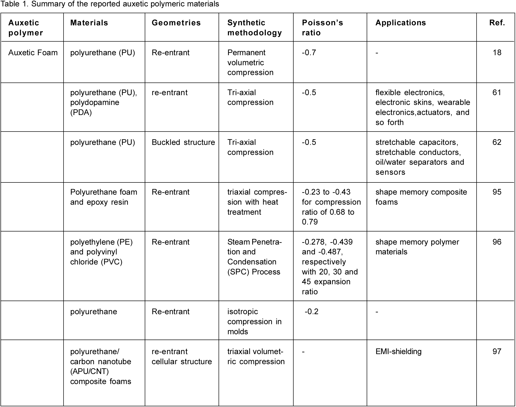
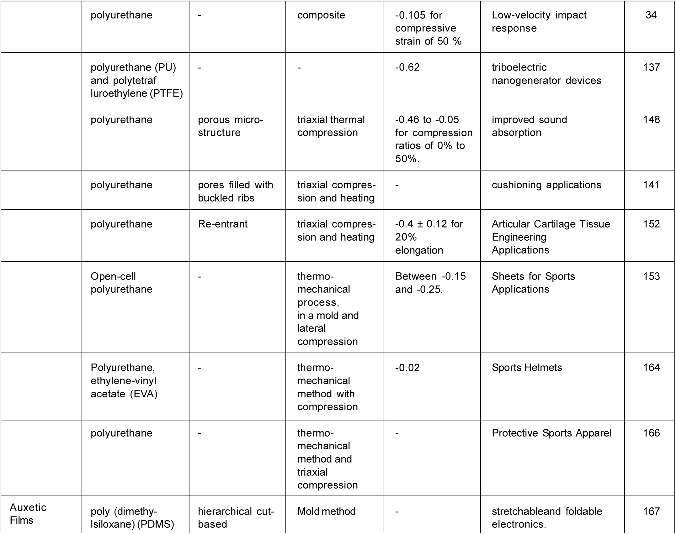
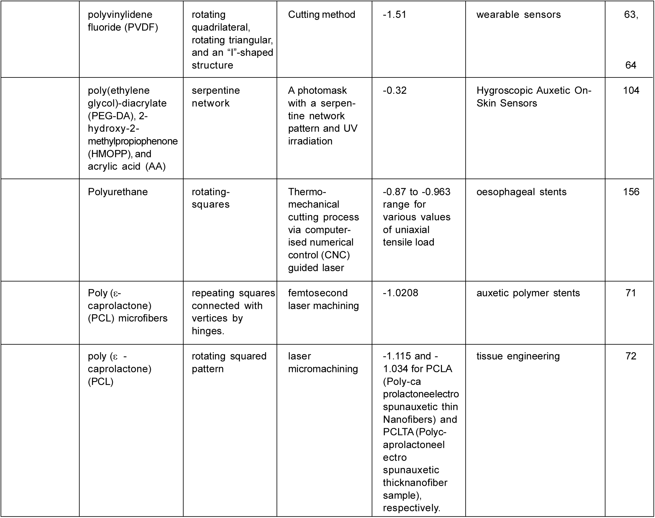

This comprehensive review provides an extensive examination of auxetic polymeric materials, with a specific emphasis on their geometries, fabrication methods, mechanical properties, and characterisation. The analysis reveals a broad range of applications, spanning fields such as biomedical, sports, impact/ballistic, acoustic, automotive, shape memory polymers, strain sensors, electromagnetic shielding, smart filters, and rehabilitation. At our DMSRDE laboratory, we are actively engaged in synthesising molecular auxetic polymers, porous gels and aerogels as well as 3D-printed polymeric structures. Also we are in the process of developing auxetic polymeric materials for suitable defence applications such as UHMWPE-based auxetic fibers and PU-based auxetic foam.
In summary, auxetic polymer-based materials represent innovative synthetic materials that are lightweight and have garnered increasing interest for diverse applications. Over the years, a diverse array of auxetic polymeric materials with various structures, including re-entrant honeycombs, rotating units, chiral structures, and perforated sheets, has been reported. The unique auxetic behaviour of these materials is closely tied to their specific geometries. Notably, existing polymeric materials exhibiting auxetic properties have been achieved by engineering porous geometries using materials with positive Poisson's ratios. However, the inherent porosity requirement in these synthetic auxetics limits their strength compared to bulk materials. Additionally, the process of engineering such structures, whether through volumetric compression, 3D printing, or mold-assisted techniques, presents challenges in terms of sample production, fabrication techniques, and associated costs. Hence, there is a clear imperative to develop polymeric materials with molecular-level designs that demonstrate auxetic behaviour. To date, only one synthetic, non-porous molecular auxetic is known with a Poisson's ratio value of -0.74±0.03.[107]
Furthermore, the development of molecular-level auxetics is confined to laboratory-scale, hindering their exploration for practical applications. This review underscores the significant role of auxetic behaviour in enhancing the mechanical properties of materials and provides valuable insights into the challenges and limitations associated with large-scale fabrication. Moreover, it serves as a source of motivation for future research in the design of auxetic polymer-based materials. By harnessing their unique properties and exploring innovative fabrication techniques, these materials hold tremendous promise for driving advancements and breakthroughs in engineering and materials science.
Acknowledgement: Authors acknowledge Head and Staff of DMSRDE Library and its internet facility centre for providing necessary support of literatures and other for internet facilities.
References
1. D. Li, J. Ma, L. Dong, R. S. Lakes. (2017). Phys. Status Solidi B, 254:1600785. [Google Scholar]
2. Y. Kim, H. Yuk, R. Zhao, S. A. Chester, X. Zhao. (2013). Nature, 558: 274-279. [Google Scholar]
3. S. Babaee, J. Shim, J. C. Weaver, E. R. Chen, N. Patel, K. Bertoldi. (2013). Adv. Mater., 25: 5044-5049. [Google Scholar]
4. U. Veerabagu, H. Palza, F. Quero. (2022). ACS Biomater. Sci. Eng., 8: 2798-2824. [Google Scholar]
5. K. K. Saxena, R. Das, E. P. Calius. (2016). Adv. Eng. Mater., 18: 1847-1870. [Google Scholar]
6. K. L. Alderson, A. Fitzgerald, K. E. Evans. (2000). Journal of Materials Science, 35: 4039-4047. [Google Scholar]
7. W. Yang, Z. M. Li, W. Shi, B.-H. Xie, M.-B. Yang. (2004). Journal of Materials Science, 39:3269-3279. [Google Scholar]
8. R. Baughman. (2003). Auxetic materials: Avoiding the shrink. Nature, 425, 667. [Google Scholar]
9. V. R., Simkins, A. Alderson, P. J. Davies. (2005). J Mater Sci, 40: 4355-4364. [Google Scholar]
10. N. Ravirala, K. L. Alderson, P. J. Davies, V. R. Simkins, A. Alderson. (2006). Textile Research Journal, 76: 540-546. [Google Scholar]
11. V. R. Simkins, N. Ravirala, P. J. Davies, A. Alderson, and K. L. Alderson. (2008). phys. stat. sol. (b), 245: 598-605. [Google Scholar]
12. A. Alderson, J. Rasburn, K. E. Evans, J. N. Grima. (2001). Membrane Technology, 137, 6-8. [Google Scholar]
13. J. L. Williams, J. L. Lewis. (1982). J Biomech Eng., 104, 50-6. [Google Scholar]
14. C. Lees, J. F. Vincent, J. E. Hillerton. (1991). Biomed Mater Eng., 1: 19-23. [Google Scholar]
15. R. Gatt, M. Vella Wood, A. Gatt, F. Zarb, C. Formosa, K. M. Azzopardi, A. Casha, T. P. Agius, P. Schembri-Wismayer, L. Attard, N. Chockalingam, J. N. Grima. (2015). Acta Biomater., 24: 201-8. [Google Scholar]
16. N. Keskar, J. Chelikowsky. (1992). Nature, 358: 222-224. [Google Scholar]
17. H. Kimizuka, H. Kaburaki, Y. Kogure. (2000). Phys. Rev. Lett., 84: 5548. [Google Scholar]
18. R. Lakes. (1987). Science, 235:1038-1040. [Google Scholar]
19. Y. J. Ma, X. F. Yao, Q. S. Zheng, Y. J. Yin, D. J. Jiang, G. H. Xu, F. Wei, Q. Zhang. (2010). Appl. Phys. Lett., 97: 061909. [Google Scholar]
20. J.-S. Kim, M. Mahato, J.-H. Oh, I.-K. Oh. (2023). Adv. Mater. Interfaces, 10: 2202092. [Google Scholar]
21. K. L. Alderson, R. S. Webber, U. F. Mohammed, E. Murphy, K. E. Evans. (1997). Applied Acoustics, 50: 23-33. [Google Scholar]
22. K. L Alderson, K. E Evans. (1992). Polymer, 33: 4435-4438. [Google Scholar]
23. R. Lakes. (1993). Adv. Mater., 5: 293-296. [Google Scholar]
24. Y. Wen, E. Gao, Z. Hu, T. Xu, H. Lu, Z. Xu, C. Li. (2019). Nat Commun, 10: 2446. [Google Scholar]
25. X. Jiang, S. Luo, L. Kang, P. Gong, W. Yao, H. Huang, W. Li, R. Huang, W. Wang, Y. Li, X. Li, X. Wu, P. Lu, L. Li, C. Chen, Z. Lin. (2015). Adv Mater., 27, 4851-7. [Google Scholar]
26. T. Bückmann, N. Stenger, M. Kadic, J. Kaschke, A. Frölich, T. Kennerknecht, C. Eberl, M. Thiel, M. Wegener. (2012). Adv. Mater., 24: 2710-2714. [Google Scholar]
27. D. Y. Fozdar, P. Soman, J. W. Lee, L. H. Han, S. Chen. (2011). Adv Funct Mater., 21: 2712-2720. [Google Scholar]
28. A. Clausen, F. Wang, J. S. Jensen, O. Sigmund, J. A. Lewis. (2015). Adv Mater., 27: 5523-7. [Google Scholar]
29. S. Quasi Mohsenizadeh, Z. Ahmad, R. Alipour, R. A. Majid, Y. Prawoto. (2019). Phys. Status Solidi B, 256: 1800587. [Google Scholar]
30. J. Hufert, A. Grebhardt, Y. Schneider, C. Bonten, S. Schmauder. (2023). Polymers, 15: 389. [Google Scholar]
31. Y. J. Park, J. K. Kim. (2013). Advances in Materials Science and Engineering, 2013: 1687-8434. [Google Scholar]
32. N. Pour, L. Itzhaki, B. Hoz, E. Altus, H. Basch, S. Hoz. (2006). Angew Chem Int Ed Engl., 45: 5981-3. [Google Scholar]
33. M. Alizadeh, I. K. Tennie, U. Steiner, A. F. M. Kilbinger. (2019). Chimia (Aarau), 73: 25-28. [Google Scholar]
34. Z. Xu, J. Chen, B. Shen, Y. Zhao, W. Zheng. (2023). ACS Materials Lett., 5: 421-428. [Google Scholar]
35. A. V. Mazaev, O. Ajeneza, M. V. Shitikova. (2020). IOP Conf. Ser.: Mater. Sci. Eng., 747: 012008. [Google Scholar]
36. H. M. A. Kolken, A. A. Zadpoor. (2017). RSC Adv., 7: 5111-5129. [Google Scholar]
37. Y. Kim, K. H. Son, J. W. Lee. (2021). Materials (Basel), 14: 6821. [Google Scholar]
38. L. J. Gibson, M. F. Ashby, G. S. Schajer, C. I. Robertson. (1982). Proc. R. Soc. Lond. A, 382: 25-42. [Google Scholar]
39. I. G. Masters, K. E. Evans. (1996). Composite Structures, 35: 403-42. [Google Scholar]
40. M. H. Fu, O. T. Xu, L. L. Hu, T. X. Yu. (2016). International Journal of Solids and Structures, 80: 284-296. [Google Scholar]
41. A. Bezazi, F. Scarpa, C. Remillat. (2005). Composite Structures, 71: 356-364. [Google Scholar]
42. T.-C. Lim. (2016). Phys. Status Solidi B, 253: 1252-1260. [Google Scholar]
43. P. S. Theocaris, G. E. Stavroulakis, P. D. Panagiotopoulos. (1997). Archive of Ap. Mech., 67: 274-286. [Google Scholar]
44. R. Magalhaes, P. Subramani, T. Lisner, S. Rana, B. Ghiassi, R. Fangueiro, D. V. Oliveira, P. B. Lourenco. (2016). Composites Part A: Applied Science and Manufacturing, 87: 86-97. [Google Scholar]
45. C. W Smith, J. N Grima, K. E Evans. (2000). Acta Materialia, 48: 4349-4356. [Google Scholar]
46. A. Boakye, Y. Chang, R. K. Raji, P. Ma. (2019). J Textile Sci & Fashion Tech., 2: JTSFT.MS.ID.000526. [Google Scholar]
47. J. N. Grima, K. E. Evans. (2000). Journal of Materials Science Letters, 19: 1563-1565. [Google Scholar]
48. J. N. Grima, K. E. Evans. (2006). J Mater Sci., 41, 3193-3196. [Google Scholar]
49. J. N., Grima, P.-S., Farrugia, R. Gatt, D. Attard. (2008). phys. stat. sol. (b), 245: 521-529. [Google Scholar]
50. P. DobnikDubrovski, N. Novak, M. Borovinšek, M. Vesenjak, Z. Ren. (2019). Polymers, 11: 1040. [Google Scholar]
51. A. Alderson, K. E. Evans. (2002). Phys. Rev. Lett., 89: 225503. [Google Scholar]
52. A. Alderson, K. L. Alderson, D. Attard, K. E. Evans, R. Gatt, J. N. Grima, W. Miller, N. Ravirala, C. W. Smith, K. Zied. (2010). Composites Science and Technology, 70: 1042-1048. [Google Scholar]
53. R. Lakes. (1991). J. Materials Science, 26: 2287-2292. [Google Scholar]
54. E. Montgomery-Liljeroth, S. Schievano, G. Burriesci. (2023). Applied Materials Today, 30: 101722. [Google Scholar]
55. D. Mousanezhad, B. Haghpanah, R. Ghosh, A. M. Hamouda, H. Nayeb-Hashemi, A. Vaziri. (2016). Theoretical and Applied Mechanics Letters, 6: 81-96. [Google Scholar]
56. J. N. Grima, R. Gatt, P.-S. Farrugia. (2008). phys. stat. sol. (b), 245, 511-520. [Google Scholar]
57. Y. Jiang, Y. Li. (2018). Sci Rep., 8: 2397. [Google Scholar]
58. X. Xin, L. Liu, Y. Liu, J. Leng. (2020). Adv. Funct. Mater., 30: 2004226. [Google Scholar]
59. W. Jiang, X. Ren, S. L. Wang, X. G. Zhang, X. Y. Zhang, C. Luo, Y. M. Xie, F. Scarpa, A. Alderson, K. E. Evans. (2022). Composites Part B: Engineering, 235: 109733. [Google Scholar]
60. R. Critchley, I. Corni, J. A. Wharton, F. C. Walsh, R. J. K. Wood, K. R. Stokes. (2013). Phys. Status Solidi B, 250, 1963-1982. [Google Scholar]
61. C. Weng, Z. Dai, G. Wang, L. Liu, Z. Zhang. (2019). ACS Appl. Mater. Interfaces, 11: 6541-6549. [Google Scholar]
62. Z. Dai, C. Weng, L. Liu, Y. Hou, X. Zhao, J. Kuang, J. Shi, Y. Wei, J. Lou, Z. Zhang. (2016). Sci. Rep., 6: 32989. [Google Scholar]
63. S. Han, S. Jung, S. Jeong, J. Choi, Y. Choi, S. Y. Lee. (2020). J. Mater. Chem. C, 8: 1556-1561. [Google Scholar]
64. X. Ye, Y. He, S. Li, H. Hu, L. Gan, J. Huang. (2022). ACS Appl. Polym. Mater., 4: 4339-4346. [Google Scholar]
65. K. E. Evans, B. D. Caddock. (1989). J. Phys. D: Appl. Phys. 22: 1883. [Google Scholar]
66. K. L. Alderson, A. P. Pickles, P. J. Neale, K. E. Evans. (1994). ActaMetallurgica et Materialia, 42: 2261-2266. [Google Scholar]
67. A. P. Pickles, K. L. Alderson, K. E. Evans. (1996). PolymEng Sci. 36: 636-642. [Google Scholar]
68. K. L. Alderson, A. Alderson, R. S. Webber, K. E. Evans. (1998). Journal of Materials Science Letters, 17: 1415-1419. [Google Scholar]
69. H. Ahn, J.-H. Wee, Y. M. Kim, W.-R. Yu, S.-Y. Yeo. (2021). Polymers, 13: 1613. [Google Scholar]
70. Y. Liu, H. Hu. (2010). Scientific Research and Essays, 5: 1052-1063. [Google Scholar]
71. S. K. Bhullar, J. Ko, Y. Cho, M. B. G. Jun. (2015). Polymer-Plastics Technology and Engineering, 54: 1553-1559. [Google Scholar]
72. S. K. Bhullar, D. Rana, H. Lekesiz, A. C. Bedeloglu, J. Ko, Y. Cho, Z. Aytac, T. Uyar, M. Jun, M. Ramalingam. (2017). Mater SciEng C Mater Biol Appl., 81: 334-340. [Google Scholar]
73. Y. Ma, Y. Zheng, H. Meng, W. Song, X. Yao, H. Lv. (2013). J Mech Behav Biomed Mater., 23: 22-31. [Google Scholar]
74. F. Tsegay, M. Elsherif, F. Alam, H. Butt. (2022). ACS Appl. Bio Mater., 5: 5545-5553. [Google Scholar]
75. P. Kunwar, A. V. S. Jannini, Z. Xiong, M. J. Ransbottom, J. S. Perkins, J. H. Henderson, J. M. Hasenwinkel, P. Soman.(2020). ACS Appl. Mater. Interfaces, 12: 1640-1649. [Google Scholar]
76. B. Yao, S. Chandrasekaran, H. Zhang, A. Ma, J. Kang, L. Zhang, X. Lu, F. Qian, C. Zhu, E. B. Duoss, C. M. Spadaccini, M. A. Worsley, Y. Li. (2020). Adv. Mater., 32: 1906652. [Google Scholar]
77. B. Cai, A. Eychmüller. (2019). Adv. Mater., 31: 1804881. [Google Scholar]
78. P. Hu, J. Lyu, C. Fu, W.-b. Gong, J. Liao, W. Lu, Y. Chen, X. Zhang. (2020). ACS Nano, 14: 688-697. [Google Scholar]
79. Y. Si, J. Yu, X. Tang, J. Ge, B. Ding. (2014). Nat Commun, 5: 5802. [Google Scholar]
80. Q. Cheng, Y. Liu, J. Lyu, Q. Lu, X. Zhang, W. Song. (2020). J. Mater. Chem. A, 8: 14243-14253. [Google Scholar]
81. K.W. Wojciechowski. (1987). Molecular Physics: An International Journal at the Interface Between Chemistry and Physics, 61: 1247-1258. [Google Scholar]
82. K. E. Evans, M. A. Nkansah, I. J. Hutchinson, S. C. Rogers. (1991). Nature, 353: 124. [Google Scholar]
83. G. Wei. (2005). phys. stat. sol. (b), 242: 742-748. [Google Scholar]
84. J. N. Grima, K. E. Evans, Chem. Commun., 2000, 1531-1532. [Google Scholar]
85. C. He, P. Liu, A. C. Griffin. (1998). Macromolecules, 31: 3145-3147. [Google Scholar]
86. C. He, P. Liu, P. J. McMullan, A. C. Griffin. (2005). phys. stat. sol. (b), 242: 576-584. [Google Scholar]
87. M. Lei, W. Hong, Z. Zhao, C. M. Hamel, M. Chen, H. Lu, H. J. Qi. (2019). ACS Appl. Mater. Interfaces, 11: 22768-22776. [Google Scholar]
88. A. H. Espera, J. R. C. Dizon, Q. Chen, R. C. Advincula. (2019). Progress in Additive Manufacturing,, 4: 245-267. [Google Scholar]
89. Z. Wang, C. Luan, G. Liao, J. Liu, X. Yao, J. Fu. (2020). Adv. Eng. Mater., 22: 2000312. [Google Scholar]
90. O. Duncan, N. Bailly, T. Allen, Y. Petit, E. Wagnac, A. Alderson. (2021). Appl. Sci., 11: 1207. [Google Scholar]
91. J. N. Grima, D. Attard, R. Gatt, R. N. Cassar. (2009). Adv. Eng. Mater, 11, 533-535. [Google Scholar]
92. Y. Li, C. Zeng, Adv. Mater. 2016, 28: 2822-2826. [Google Scholar]
93. M. Bianchi, F. Scarpa, M. Banse, C. W. Smith. (2011). Acta Materialia, 59: 686-691. [Google Scholar]
94. Q. Zhang, W. Lu, F. Scarpa, D. Barton, R. S. Lakes, Y. Zhu, Z. Lang, H.-X. Peng. (2020). Applied Materials Today, 20: 100775. [Google Scholar]
95. Y. Yao, Y. Luo, Y. Xu, B. Wang, J. Li, H. Deng, H. Lu. (2018). Composites Part B, 152: 1-7. [Google Scholar]
96. D. Fan, M. Li, J. Qiu, Ha. Xing, Z. Jiang, T. Tang. (2018). ACS Appl. Mater. Interfaces, 10: 22669-22677. [Google Scholar]
97. O. Duncan, F. Clegg, A. Essa, A. M. T. Bell, L. Foster, T. Allen, A. Alderson. (2019). Phys. Status Solidi B, 256: 1800393. [Google Scholar]
98. D. Y. Fozdar, P. Soman, J. W. Lee, L.-H. Han, S. Chen. (2011). Adv. Funct. Mater., 21: 2712-2720. [Google Scholar]
99. S. Li, M. Hu, L. Xiao, W. Song. (2020). Thin-Walled Structures, 157: 107153. [Google Scholar]
100. C. Yang, H. D. Vora, Y. Chang. (2018). Smart Mater. Struct., 27: 025012. [Google Scholar]
101. D. Olvera, M. Sohrabi, G. Hendy, M. G. Monaghan. (2020). Adv. Funct. Mater., 30: 1909880. [Google Scholar]
102. S. Malakooti,A. B. M. ShaheenudDoulah, Y. Ren, V. N. Kulkarni, R. U. Soni, V. A. Edlabadkar, R. Zhang, S. L. Vivod, C. Sotiriou-Leventis, N. Leventis, H. Lu. (2021). ACS Appl. Polym. Mater., 3: 5727-5738. [Google Scholar]
103. S. Pruksawan, H. L. Chee, Z. Wang, P. Luo, Y. T. Chong, W. Thitsartarn, F. Wang. (2022). Chem. Asian J., 17: e202200677. [Google Scholar]
104. H. W. Kim, T. Y. Kim, H. K. Park, I.You, J. Kwak, J. C. Kim, H. Hwang, H. S. Kim, U. Jeong. (2018). ACS Appl. Mater. Interfaces, 10: 40141-40148. [Google Scholar]
105. A. Agrawal, P. Joo, N. Teo, S. C. Jana. (2022). ACS Appl. Polym. Mater., 4: 3791-3801. [Google Scholar]
106. D. Mistry, P. B. Morgan, J. H. Clampc, H. F. Gleeson. (2018). Soft Matter, 14: 1301-1310. [Google Scholar]
107. D. Mistry, S. D. Connell, S. L. Mickthwaite, P. B. Morgan, J. H. Clamp, H. F. Gleeson. (2018). Nat Commun, 9: 5095. [Google Scholar]
108. D. Fan, Z. Shi, N. Li, J. Qiu, H. Xing, Z. Jiang, M. Li, T. Tang. (2020). ACS Appl. Mater. Interfaces, 12, 48040-48048. [Google Scholar]
109. L. Tian, J. Yang, X. You, M. Wang, X. Ren, X. Zhang, S. Dong. (2022). Sci. Adv., 8: eabo1014. [Google Scholar]
110. M. Mir, M. N. Ali, J. Sami, U. Ansari. (2014). Advances in Materials Science and Engineering, 1687-8434. [Google Scholar]
111. K. L. Alderson, V. R. Simkins, V. L. Coenen, P. J. Davies, A. Alderson, K. E. Evans. (2005). phys. stat. sol. (b), 242: 509-518. [Google Scholar]
112. H. M., El-Dessouky, C. McHugh. (2022). Sci Rep, 12: 22593. [Google Scholar]
113. K. L. Alderson, A. Fitzgerald, K. E. Evans. (2000). Journal of Materials Science, 35: 4039-4047. [Google Scholar]
114. 4. K. L. Alderson, R. S. Webber, A. P. Kettle, K. E. Evans. (2005). PolymEngSci, 45: 568-578. [Google Scholar]
115. Y. Jiang, Y. Li. (2018). Adv. Eng. Mater., 20: 1700744. [Google Scholar]
116. J. Dirrenberger, S. Forest, D. Jeulin. (2013). Int J Mech Mater Des, 9: 21-33. [Google Scholar]
117. T. Li, F. Liu, L. Wang. (2020). Composites Part B: Engineering, 198:108229. [Google Scholar]
118. J. B. Choi, R. S. Lakes. (1996). Int J Fract, 80: 73-83. [Google Scholar]
119. J. P. Donoghue, K. L. Alderson, K. E. Evans. (2009). phys. stat. sol. (b), 246: 2011-2017. [Google Scholar]
120. R. Naboni, L. Mirante. (2015). In: São Paulo: Blucher, 2: 129-136. [Google Scholar]
121. A. Boakye, Y. Chang, R. K. Raji, P. Ma. (2019). J Textile Sci & Fashion Tech., 2, JTSFT.MS.ID.000526. [Google Scholar]
122. C. Qi, A. Remennikov, L.-Z. Pei, S. Yang, Z.-H. Yu, T. D. Ngo. (2017). Composite Structures, 180: 161-178. [Google Scholar]
123. M. Najafi, H. Ahmadi, G. Liaghat. (2021). Materials Today: Proceedings, 34: 350-355. [Google Scholar]
124. J. Rasburn, P. G. Mullarkey, K. E. Evans, A. Alderson, S. Ameer-Beg, W. Perrie. (2001) AIChE J., 47: 2623-2626. [Google Scholar]
125. M. Wallbanks, M. F. Khan, M. Bodaghi, A. Triantaphyllou, A. Serjouei. (2022). Smart Mater. Struct., 31: 023002. [Google Scholar]
126. A. Alderson, J. Rasburn, S. Ameer-Beg, P. G. Mullarkey, W. Perrie, K. E. Evans. (2000) Ind. Eng. Chem. Res., 39: 654-665. [Google Scholar]
127. D. Attard, A. R. Casha, J. N. Grima. (2018). Materials, 11: 725. [Google Scholar]
128. C. Lira, P. Innocenti, F. Scarpa. (2009). Composite Structures, 90: 314-322. [Google Scholar]
129. L. Yang, O. Harrysson, H. West, D. Cormier. (2015). International Journal of Solids and Structures, 69-70: 475-490. [Google Scholar]
130. S. Jin, Y. P. Korkolis, Y. Li. (2019). International Journal of Solids and Structures, 174-175: 28-37. [Google Scholar]
131. N. Novak, O. Duncan, T. Allen, A. Alderson, M. Vesenjak, Z. Ren. (2021). Mechanics of Materials, 157: 103818. [Google Scholar]
132. X. Y. Chen, O. Hamdi, D. Rodrigue. (2023). Polym Adv Technol., 34: 228-237. [Google Scholar]
133. V. C. Vinay, D. S. M. Varma, M. R. Chandan, P. Sivabalan, A. K. Jaiswal, S. Swetha, B. Kaczmarek, A, Sionkowska. (2022). Polym. Bull., 79: 4233-4250. [Google Scholar]
134. N. Li, Z. Liu, X. Shi, D. Fan, H. Xing, J. Qiu, M. Li, T. Tang. (2022). Adv. Eng. Mater., 24: 2100859. [Google Scholar]
135. N. Novak, L. Biasetto, P. Rebesan, F. Zanini, S. Carmignato, L. Krstuloviæ-Opara, M. Vesenjak, Z. Ren. (2021). Additive Manufacturing, 45: 102022. [Google Scholar]
136. L. Gu, Q. Xu, D. Zheng, H. Zou, Z. Liu, Z. Du. (2020). Textile Research Journal., 90: 2411-2427. [Google Scholar]
137. J. Lisiecki, T. B3a¿ejewicz, S. K3ysz, G. Gmurczyk, P. Reymer, G. Miku3owski. (2013). Phys. Status Solidi B, 250: 1988-1995. [Google Scholar]
138. J. Dirrenberger, S. Forest, D. Jeulin. (2013). Int J Mech Mater Des, 9: 21–33 [Google Scholar]
139. R. P. Bohara, S. Linforth, T. Nguyen, A. Ghazlan, T. Ngo. (2023). Engineering Structures, 276: 115377. [Google Scholar]
140. Z. Chen, Z. Wang, S. Zhou, J. Shao, X. Wu. (2018). Materials (Basel), 27: 1095. [Google Scholar]
141. L. Jiang, H. Hu. (2017). Composite Structures, 169, 62-68. [Google Scholar]
142. M. Asad, T. Zahra, D. P. Thambiratnam, T. H. T. Chan, Y. Zhuge. (2021). Construction and Building Materials, 311: 125170. [Google Scholar]
143. G. Imbalzano, P. Tran, T. D. Ngo, P. V. S. Lee. (2016). Composite Structures, 135: 339-352. [Google Scholar]
144. J.-S. Kim, M. Mahato, J.-H. Oh, I.-K. Oh. (2023). Adv. Mater. Interfaces, 10: 2202092. [Google Scholar]
145. M.-H. Yoon, J.-H. Oh. (2023). Advanced Composite Materials, 32: 225-236. [Google Scholar]
146. M. Wallbanks, M. F. Khan, M. Bodaghi, A. Triantaphyllou, A. Serjouei. (2022). Smart Mater. Struct., 31: 023002. [Google Scholar]
147. W. Hou, X. Yang, W. Zhang, Y. Xia. (2017). International Journal of Crashworthiness, 23: 366-376. [Google Scholar]
148. A. Lendlein, H. Jiang, O. Jünger, R. Langer.(2005). Nature, 434: 879-882. [Google Scholar]
149. J. Rossiter, K. Takashima, F. Scarpa, P. Walters, T. Mukai. (20140). Smart Mater. Struct., 23: 045007. [Google Scholar]
150. D. Fan, M. Li, J. Qiu, H. Xing, Z. Jiang, T. Tang. (2018). ACS Appl. Mater. Interfaces, 10: 22669-22677. [Google Scholar]
151. S. Pandini, N. Inverardi, G. Scalet, D. Battini, F. Bignotti, S. Marconi, F. Auricchio. (2020). Mechanics Research Communications, 103:103463. [Google Scholar]
152. S. L. Zhang, Y.-C. Lai, X. He, R. Liu, Y. Zi, Z. L. Wang. (2017). Adv. Funct. Mater., 27: 1606695. [Google Scholar]
153. R. Chen, R. Yu, X. Pei, W. Wang, D. Li, Z. Xu, S. Luo, Y. Tang, H. Deng. (2021). New J. Chem., 45: 8370-8385. [Google Scholar]
154. J. Kruzelak, A. Kvasnicakova, K. Hlozekova, I. Hudec. (2021). Nanoscale Adv., 3:123-172. [Google Scholar]
155. D. Attard, A.R. Casha, J.N. Grima. (2018). Filtration Properties of Auxetics with Rotating Rigid Units. Materials, 11: 725. https://doi.org/10.3390/ma11050725 [Google Scholar] [CrossRef]
156. C. V. Vinay, D. M. Varma, M. R. Chandan, P. Sivabalan, A. K. Jaiswal, S. Swetha, A. Sionkowska, B. Kaczmarek. (2021). Polym Int, 70: 1631-1639. [Google Scholar]
157. Y. J. Park, J. K. Kim. (2013). Adv. Mater. Sci. Eng. 2013: 853289-853294. [Google Scholar]
158. M. Kapnisi, C. Mansfield, C. Marijon, A. Guex, F. Perbellini, I. Bardi, E. J. Humphrey, J. L. Puetzer, D. Mawad, D. C. Koutsogeorgis, D. J. Stuckey, C. M. Terracciano, S. E. Harding, M. M. Stevens. (2018). Adv. Funct. Mater. 28: 1800618-1800630. [Google Scholar]
159. E. Sousa, P. Serruys, M. Costa. (2003). Circulation, 107: 2274-2279. [Google Scholar]
160. M. N. Ali, J. J. Busfield, I. U. Rehman. (2014). J Mater Sci Mater Med., 25: 527-53. [Google Scholar]
161. H. C. Cheng, F. Scarpa, T. H. Panzera, I. Farrow, H.-X. Peng. (2019). Phys. Status Solidi B, 256: 1800411. [Google Scholar]
162. K. Günaydýn, G. Sala, H. S. Türkmen, A. M. Grande. (2022). Procedia Structural Integrity, 35: 237-246. [Google Scholar]
163. A. Joseph, V. Mahesh, D. Harursampath. (2021). Adv. Manuf., 9: 342-368 [Google Scholar]
164. T. Allen, O. Duncan, L. Foster, T. Senior, D. Zampieri, V. Edeh, A. Alderson. (2017). Snow Sports Trauma and Safety, Springer, Cham. [Google Scholar]
165. O. Duncan, T. Shepherd, C. Moroney, L. Foster, P. D. Venkatraman, K. Winwood, T. Allen, A. Alderson. (2018). Appl. Sci., 8: 941. [Google Scholar]
166. W. S. Ng, C. S. Lee, C. H. Chuah, S.-F. Cheng. (2017). Industrial Crops and Products, 97: 65-78. [Google Scholar]
167. B. Das, U. Konwar, M. Mandal, N. Karak. (2013). Industrial Crops and Products, 44: 396-404. [Google Scholar]
168. T. Allen, T. Hewage, C. Newton-Mann, W. Wang, O. Duncan, A. Alderson. (2017). Phys. Status Solidi B, 254:1700596. [Google Scholar]
169. M. Sanami, N. Ravirala, K. Alderson, A. Alderson. (2014). Procedia Engineering, 72: 453-458. [Google Scholar]
170. L. Foster, P. Peketi, T. Allen, T. Senior, O. Duncan, A. Alderson. (2018). Appl. Sci., 8: 354. [Google Scholar]
171. C. Moroney, A. Alderson, T. Allen, M. Sanami, P. Venkatraman. (2018). Proceedings, 2: 251. [Google Scholar]
Cite This Article
 Copyright © 2023 The Author(s). Published by Tech Science Press.
This work is licensed under a Creative Commons Attribution 4.0 International License , which permits unrestricted use, distribution, and reproduction in any medium, provided the original work is properly cited.


 Submit a Paper
 Propose a Special lssue
 View Full Text
 Download PDF
 Downloads
 Citation Tools