
 Submit a Paper
 Propose a Special lssue
 Open Access
ARTICLE

Impact and Residual Flexural Properties of 3D Integrated Woven Spacer Composites
State Key Laboratory of Mechanics and Control for Aerospace Structures, Nanjing University of Aeronautics and Astronautics, Nanjing, 210016, China
* Corresponding Author: Deng’an Cai. Email:
(This article belongs to the Special Issue: Damage and Fracture of Polymer Composites)
Journal of Polymer Materials 2025, 42(3), 873-891. https://doi.org/10.32604/jpm.2025.064978
Received 28 February 2025; Accepted 24 July 2025; Issue published 30 September 2025
 View Full Text
 Download PDF
Abstract
This study investigates the low-velocity impact and post-impact flexural properties of 3D integrated woven spacer composites, focusing on their orthotropic behavior when tested along two principal directions, i.e., warp (X-type) and weft (Y-type) directions. The same composite material was tested in these orientations to evaluate the differences in impact resistance and residual bending strength. Specimens were fabricated via vacuum-assisted molding and tested at 2, 3, 5, and 7 J impact energies using an Instron Ceast 9350 drop-weight impact testing machine, in accordance with ASTM D7136. Post-impact flexural tests were performed using a four-point bending method in accordance with ASTM D7264. The absorbed energy increased from 1.97 to 6.98 J, and the panel damage area ranged from 121 to 361 mm2 as impact energy roses. Specimens tested in the weft direction (Y-type) showed greater residual strength (up to 15.83 N) and displacement (up to 0.538 mm) than those tested in the warp direction (X-type). Ultrasonic C-scan imaging revealed localized matrix cracking and fiber failure damage patterns. Results emphasize the directional differences in impact resistance and residual bending properties, highlighting the importance of material orientation in structural applications. This study provides a foundation for utilizing 3D woven spacer composites in lightweight, damage-tolerant structural components.Keywords
Composite sandwich materials exhibit more complex mechanisms and longer fatigue life than metals due to their heterogeneous composition of fiber, resin, and foam components [1,2]. This complexity results from the interplay between various material phases, leading to distinct failure modes under cyclic loading [3]. Fiber-reinforced composites featuring foam-filled cores are advancing quickly, propelled by innovations in material science to address the requirements of industries like aviation, aerospace, marine, and automotive engineering [4–9]. Among these, 3D integrated woven spacer composites demonstrate considerable improvements over standard woven fabrics, particularly when used in sandwich structures. Recent studies have highlighted the high integrity and stability of woven spacer fabrics, making them suitable for composite reinforcement [10]. 3D integrated woven spacer composites consist of two fabric faces bonded by piles woven into the deck layers, forming an integrated hollow core [11,12]. Compared to composite laminates, 3D integrated woven spacer composite structures offer higher durability, increased energy absorption, strong structural integrity, reduced cost, and a design that reduces delamination issues common in traditional sandwich structures [13–15].
Despite these advantages, composite sandwich structures remain prone to internal delamination, which may not be externally visible, leading to significant reductions in mechanical performance. Bending strength, for instance, can decrease to less than 40% of its original value [16]. Consequently, structural damage due to impact, especially low-velocity impacts, has drawn growing attention. Under such loading, composite components may experience matrix cracking, fiber breakage, and interfacial separation, impairing material integrity. Therefore, understanding and evaluating the damage tolerance of these materials, defined by their ability to maintain structural function despite flaws, is essential. This includes quantifying initial defect size, residual strength thresholds, and damage propagation behavior. Periodical inspections and accurate damage characterization methods must be employed to ensure composites sustaining required performance throughout service life. Sensors are also widely utilized to monitor specimen responses and identify failure mechanisms under impact and bending loads [17–19].
3D integrated woven spacer composite materials combine the architectural characteristics of sandwich structures with the robustness of three-dimensional woven fabrics, forming lightweight yet resilient components. Altering the internal linkage between the upper and lower layers enables the creation of diverse hollow geometries triangles, trapezoids, rectangles, “X” shapes, and “8” shapes. These internal structures distribute stress uniformly, enhancing load-bearing capacity. Among them, “X” and “8” shapes provide denser core connectivity and improved load transfer. Test results confirm that these geometries exhibit superior strength and stability [20]. Recent research by Hiremath et al. [21] further validated the effectiveness of these core geometries in optimizing the structural performance of woven composites, particularly in terms of enhanced energy absorption and flexural strength. Additionally, Zhu et al. [22] investigated the impact of different core configurations on stress distribution and mechanical properties, demonstrating that “X” and “8” shapes significantly improved the overall load resistance compared to conventional geometries. The enhanced forming stability of core yarns also contributed to improved structural performance. Research indicates that core architecture significantly affects overall mechanical behavior and deformation resistance [23].
Numerous studies have examined the mechanical behavior of 3D woven spacer composites with hollow core structures. Shiah et al. [24] assessed their load response and integrity using X-ray computed tomography. Zhu et al. [25] performed tensile tests on specimens with 15 mm core heights, obtaining fracture stress and modulus values. They also correlated core height and face sheet thickness with bending behavior, noting that increasing core height improved longitudinal bending response, though it reduced in-plane compressive resistance. van Vuure et al. [26] evaluated compressive strength and shear modulus of woven sandwich composite, confirming its excellent load resistance. These researches highlight that geometric parameters significantly influence the mechanical properties of 3D woven sandwich structures.
Several researchers have explored impact response in such composites. Hosur et al. [27] and Neje and Behera [28] studied low-velocity impact resistance in various panel types, including hybrid glass/carbon fiber laminates. Enhancements such as aluminum face sheets improved panel resilience. It should be emphasized that the unit dimensions (height, width, and inclination angle) affected greatly the impact energy absorption and failure loads. Mechanical characterization under bending and pendulum impact revealed that core configuration and temperature affected failure modes, too [29,30]. Ahmad Hosseini et al. [31] found that thinner hollow cores resisted contact damage better, while thicker ones absorbed more energy. Castellanos and Prabhakar [32] analyzed complex woven face sheets, associating yarn topology with impact and compression strength.
During low-velocity impacts, more energy is absorbed by the material near the point of contact, leading to localized damage. Designs with floating yarns or intricate topologies improve stress dispersion, minimizing internal fracture. Although significant research exists on foam or honeycomb sandwich composites, studies on residual flexural behavior of 3D integrated woven spacer composites remain limited. While nano clay reinforcement has been shown to enhance impact strength, research on directional impact response especially post-impact bending strength across principal directions remains underdeveloped. Compared to traditional sandwich cores, these spacer fabrics may offer direction-sensitive mechanical advantages [33].
Recent advancements, such as 3D-printed gyroid core structures [34], anisotropic failure mapping [35], and hybrid layer optimization [36,37], have been made in sandwich structures. Olhan et al. [38] investigated the effect of different fibres and architectures on the impact and post-impact performance of woven composites. It was showed that optimizing these factors could enhance both impact resistance and flexural strength, crucial for aerospace and automotive applications. They highlight the key role of fiber-matrix interactions and core material configurations in improving material behavior under low-velocity impact. The results emphasize the importance of multi-layer composite structures in improving damage resistance and energy absorption, ultimately enhancing the mechanical performance of woven composites for high-performance applications.
Present study investigates the low-velocity impact behavior and residual bending performance of 3D integrated woven spacer composites, specifically tested along the warp and weft directions. Impact tests are performed using standardized energy levels (2 to 7 J). Ultrasonic C-scan images are used for damage analysis. And four-point bending tests under ASTM guidelines are performed to investigate the post-impact flexural behavior. This work aims to clarify how impact energy and loading direction affect damage morphology and post-impact flexural properties, offering guidance for improved structural design and durability assessment.
The three-dimensional (3D) integrated woven spacer composite fabrics used in this study were supplied by Nanjing Fiberglass Research & Design Institute. The composite preforms were manufactured using carbon fiber (CCF300), known for its exceptional strength-to-weight ratio and impact resistance. The fabric was produced using advanced integrated weaving technology on a Vanderweil VTR42 double-rapier loom, which tightens the fabric surface by adjusting the warp tension. The weft tension coefficient is maintained between 3.5 and 5.0, while the pile warp tension coefficient is set to 5.0, controlled by the fabric’s height. The composite panels consist of top and bottom face sheets, each with a thickness of 1 mm, resulting in a total face sheet thickness of 2 mm. The pile yarn height is 8 mm, forming the core structure of the sandwich composite. The woven architecture, including the hollow core structure formed by the pile yarns, enhances the composite’s impact resistance and energy absorption. The material is tested in two orientations: warp (denoted as “X”) and weft (denoted as “Y”) directions, to examine the directional mechanical properties of the composite material.
The composite is fabricated using vacuum-assisted resin infusion molding process, which begins with the creation of a vacuum to remove air from the fiber-reinforced composite. After the vacuum is established, E51 epoxy resin is injected into the system, ensuring complete impregnation of the fibers and fabrics. Once fully impregnated, the vacuum bag is removed, allowing the core material to rise vertically from the base. The composite is then cured at 60°C for eight hours, completing the formation of the 3D integrated woven spacer composite.
During the manufacturing process, the core yarns may experience tilting slightly due to the resin infusion and pressure application. The inclination angles of the yarns in both the warp (X-type) and weft (Y-type) directions are very small, with a degree of randomness in their orientation. Therefore, this study does not provide precise measurements of these tilting angles. In future research, it is suggested that CT imaging or similar advanced techniques should be adopted to quantify the tilting angles of the core yarns more accurately to provide a better understanding of how the small yarn tilting affects the composite’s mechanical properties, including impact resistance and bending strength.
Fig. 1 illustrates the schematic representations of the three-dimensional integrated woven spacer composite. Using a diamond-tipped saw, the material was cut into plates with dimensions of 400 mm × 50 mm × 10 mm. Twenty different samples had been created for the low-velocity impact test as well as the post-impact bending test. Within the circumstances of the post-impact bending test, a total of ten samples were used for the weft bending, designated as type X, and ten samples were utilized for the warp bending, designated as type Y. Impact tests were performed in accordance with the drop weight impact test standard ASTM D7136/D7136M [39]. In each batch of ten samples, eight samples underwent impact testing using drop weight impact, whilst the remaining two samples were not subjected to impact load. Table 1 lists the classification of the low-velocity impact tests.
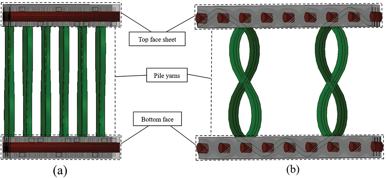
Figure 1: The structural diagram of the 3D integrated woven spacer composite: (a) warp view (Y-type) and (b) weft view (X-type)

Before the low-velocity impact test, all samples were conducted ultrasonic C-scan to guarantee that no initial damage existed in the specimens. Each test group should include at least three valid data points to ensure statistical reliability and reduce variability. In present study, however, only two samples per type (warp and weft orientations) were tested due to limit supplied material. Hence, it may introduce uncertainty in the results due to limited statistical reliability. In other words, the smaller sample size might lead to increased variability, affecting the accuracy and reproducibility of the findings slightly.
The low-velocity impact test was conducted following the guidelines of ASTM D7136/D7136M using the Instron Ceast 9350 (drop weight impact testing machine). The testing apparatus includes an impactor, a platform for impact, a system for acceleration, and a control panel. Additionally, the machine is equipped with data acquisition, processing, and software control systems, ensuring accurate and dependable results for intricate tests. The impactor mass is 2.277 kg, and the impactor shape is hemispherical, with a diameter of 16 mm. Fig. 2 shows the testing machine and setups. The impact testing machine supported the specimen on an impact platform featuring a 125 mm × 75 mm rectangular through-hole, and fixed it with four rubber-tipped linkages, as depicted in Fig. 2b. Furthermore, the testing machine incorporates an anti-rebound device shown in Fig. 2c, used to successfully protect the sample from a second impact.
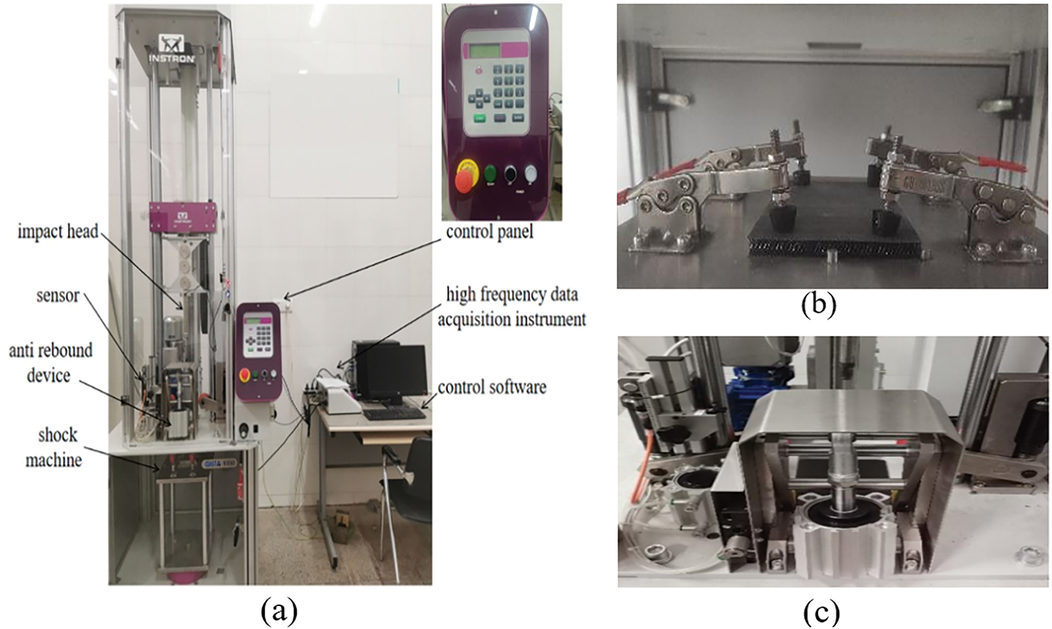
Figure 2: A configuration of drop weight impact test: (a) Low velocity impact test machine, (b) Impact boundary conditions, and (c) Anti-rebound device
The specimen dimensions used in the drop-weight tests are 400 mm × 50 mm × 10 mm. The test fixture has 125 mm × 75 mm opening, hence, the spaceman width (50 mm) is smaller than the fixture opening.
With the adjustment of the drop height on the testing machine, impact tests at low velocity using varying impact energy levels can be achieved. Tests conducted at four distinct impact energy levels produced four characteristic damage patterns in the 3D integrated woven spacer composite. At 2 J impact energy, matrix damage was observed on the specimen’s upper surface; at 3 J impact energy, the upper panel developed cracks; at 5 J impact energy, the upper panel was fully penetrated; and at 7 J impact energy, the entire specimen was perforated by the impactor. These four impact energy levels were selected to study how damage types affect the structure’s flexural behavior and failure modes. After testing, surface damage and dent sizes were visually inspected. Damage distribution and mechanisms were analyzed using immersion ultrasonic C-scanning techniques. The Ultra PAC C-scan system includes a 100 MHz A/D converter, a 5 MHz ultrasonic probe, and scans at 0.5 mm/s.
2.3 Four-Point Bending Test after Impact
After completing the low-velocity impact test, four-point bending tests were performed according to the ASTM D7264/D7264M standard [40] using the 16 impacted test specimens and 4 non-impacted specimens of Types X and Y to determine the bending performance of the specimen after different energy impacts. The four-point bending test was carried out on an MTSE45 microprocessor-based universal testing machine. The machine has a maximum load capacity of 300 kN with a relative error below 0.5%. Quasi-static loading was achieved using displacement control loading mode at a rate of 3 mm/min. Tests were conducted in a dry, room-temperature environment.
Fig. 3 illustrates the schematic diagram of four-point bending test. Table 2 lists the parameters (e.g., span and loading rate) used in the bending tests.
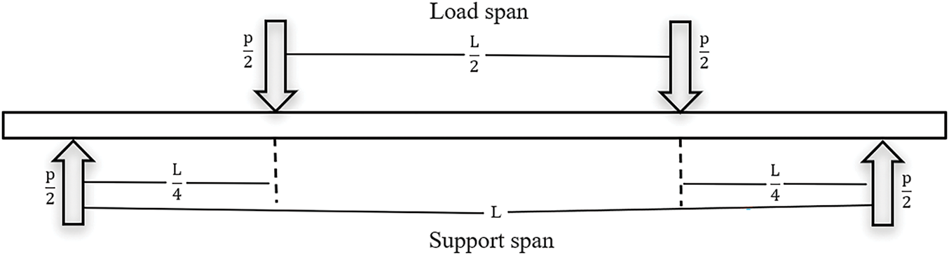
Figure 3: Schematic diagram of four-point bending test

Due to limited material provided by the supplier, only two specimens per test condition were tested repeatedly, as shown in Table 3. This should be good enough for typical for an initial evaluation of the material behavior However, we recognize that this sample size may not be enough to provide sufficient statistical reliability, as smaller sample sizes can introduce increased variability and potentially affect the accuracy and reproducibility of the results. To ensure more statistically reliable data and meet ASTM standards, the sample size should be increased to at least three specimens per test condition. This is beyond the scope of the paper.

Fig. 4 shows the four-point bending test specimen installation method with the loading fixtures arranged and placed in the testing machine (support rods spanning the width of the specimen, and two loading rods located at the top of the specimen, spanning the width of the specimen). Vertical force is exerted via the loading rods, while the support rods remain secured within the testing machine. At the same time, connect the sensor to the fixture and the sample, and then connect it to the recording instrument.
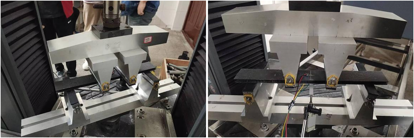
Figure 4: Four-point bending test specimen installation method
3.1 Low-Velocity Impact Test at Different Energies
The average impact test results from two 3D integrated woven spacer composite specimens for each energy level and specimen type (X-type and Y-type) are summarized in Table 4. The data include the maximum peak impact load, absorbed energy, energy absorption rate, and damage area were recorded for both the X-type (warp direction) and Y-type (weft direction) composite samples. The energy levels are 2, 3, 5, and 7 J, respectively.

Fig. 5 shows the average force-time curves for X-type (warp) and Y-type (weft) specimens under impact energies of 2, 3, 5, and 7 J. These curves indicate a higher peak load for X-type specimens at each energy level, demonstrating their superior resistance to impact compared to Y-type specimens.
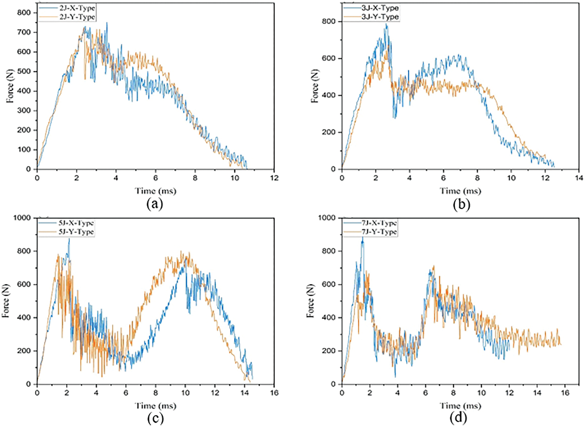
Figure 5: Force-time curves from the low-velocity impact test with four energy levels: (a) 2 J, (b) 3 J, (c) 5 J, and (d) 7 J. Data represents the average results from two specimens for each energy level and specimen type (X-type and Y-type)
At 2 and 3 J impact energies, the impactor primarily causes damage to the upper panel. The force-time curves for these energy levels show a linear rise in load until the initial peak is reached (approximately at t = 2.8 ms), followed by a sharp drop in load due to the matrix cracking and fiber fracture. This is typical of damage initiation at lower impact energies. Following the initial peak load, the failure of the core material linking the upper and lower panels occurs, leading to crack propagation in the upper panel, which results in fluctuating load patterns during the impact process.
At 5 and 7 J, the impactor penetrates the upper panel, leading to significant core material failure and damage to the lower panel. This is reflected in the force-time graph, where two distinct peaks are observed. The initial peak represents the penetration of the upper panel, followed by the core material failure at the point of impact between the upper and lower panels. As the impactor continues to strike the lower panel, a second peak emerges in the graph, which corresponds to the damage to the lower panel. This second peak is indicative of damage progression throughout the composite structure.
The analysis of the load-displacement curves for WCX, WDX, WCY, and WDY at 5 J impact energy reveals that WCX exhibits a second peak marginally below the first, indicating that damage has occurred to the core material close to the lower panel in the impacted area, while the fibers in the panel remain largely intact. In contrast, the other curves show similar peak loads, without significant deviation. Once the impactor passes the second peak, the upper panel is fully penetrated, and the lower panel is breached, causing the failure of all fiber bundles in contact with the impactor.
Fig. 6 presents the damage patterns observed on the upper and lower panel surfaces after a 7 J impact. The upper panel shows complete penetration, indicating a severe compromise in the material’s structural integrity due to the high impact energy. In contrast, the lower panel exhibits partial perforation, which suggests that while the impactor has caused significant damage, the core material and fiber layers in the lower panel still provide some resistance to further penetration. This differential damage between the upper and lower panels highlights the failure progression under high-energy impacts, where the upper panel is typically the first to fail, followed by core material and finally the lower panel damage. The extent of perforation in the lower panel reveals the energy dissipation mechanisms and the overall material resilience at higher impact levels.
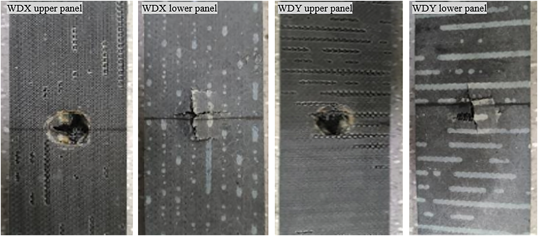
Figure 6: WDX and WDY upper and lower panel surfaces after impact with 7 J energy
Fig. 7 displays the C-scan images of the 3D integrated woven spacer composites after impact by varying energy levels. The images highlight significant differences in damage patterns between X-type and Y-type specimens.
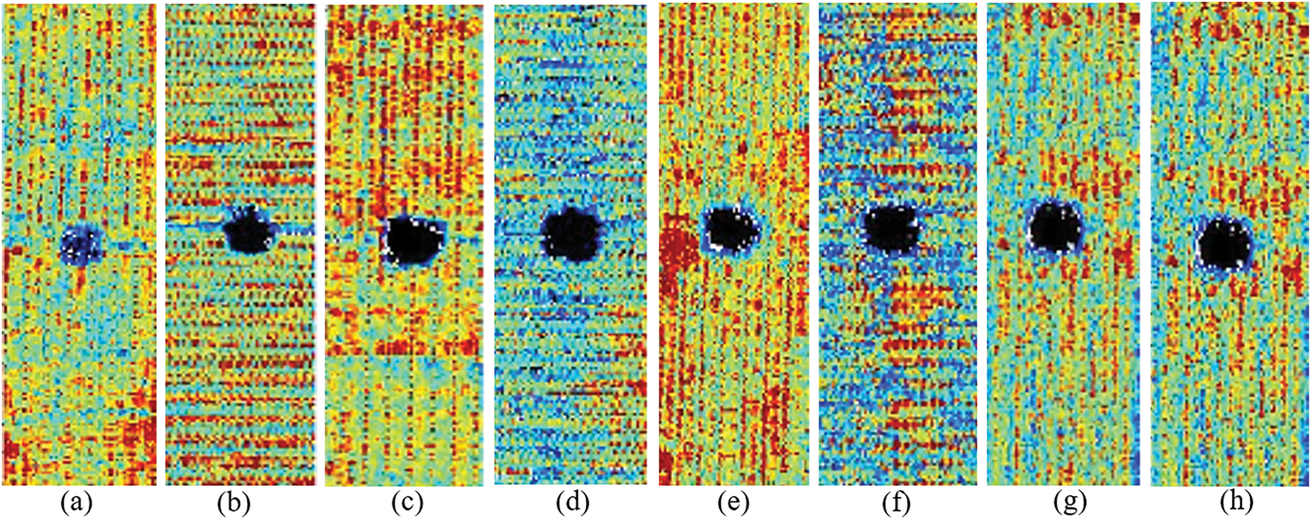
Figure 7: C-scan impact damage images: (a) WAX, (b) WBX, (c) WCX, (d) WDX, (e) WAY, (f) WBY, (g) WCY and (h) WDY
Specifically, X-type specimens exhibit smaller, more localized damage zones compared to Y-type specimens, indicating superior impact resistance in the warp direction due to the structural configuration of the fibers in the that direction, which likely enhances the stress distribution and minimizes delamination. In contrast, Y-type samples, oriented in the weft direction, display a larger damage zone, possibly due to the core configuration and structural differences. Additionally, the boundary conditions for both type specimens during testing, such as their supporting structures and fiber orientation, likely influenced the extent of damage. This suggests that the warp direction (X-type) offers better performance in terms of damage containment compared to the weft direction (Y-type).
Fig. 8 provides the average energy-time curves for impact tests conducted at 2, 3, 5, and 7 J energy levels. The curves illustrate the energy absorption behavior of the composites and correlate it with the damage area observed in the specimens. As the impact energy increases, both the absorbed energy and the extent of the damage grow, but the damage is largely contained within the impact zone. This indicates that the material maintains high resistance to damage propagation outside the immediate impact area. As the impact energy increases, the damaged area enlarges but is within the area slightly larger than the largest impactor’s cross-section. Importantly, no significant damage was observed outside the immediate impact zone, suggesting that the damage to the 3D integrated woven spacer composites is concentrated locally and does not propagate extensively outside the impact zone. In other words, the material exhibits a high degree of localized damage resistance, with minimal damage spread beyond the impact zone.
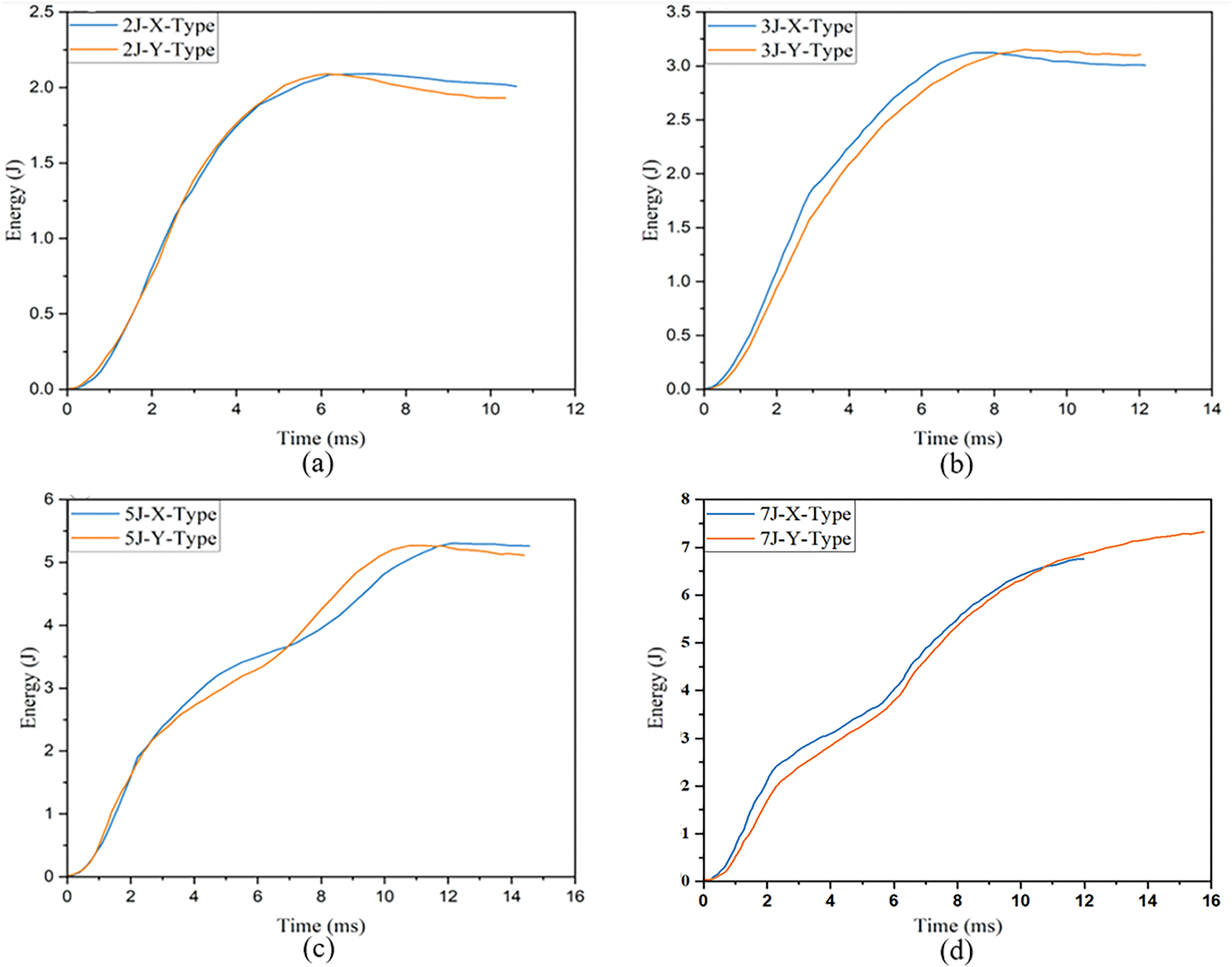
Figure 8: Low-velocity impact test energy-time curves with different energies: (a) 2 J, (b) 3 J, (c) 5 J, and (d) 7 J. Data represents the average results from two specimens for each energy level and specimen type (X-type and Y-type)
3.2 Damage Mechanisms of Low-Velocity Impacts at Different Energies
Figs. 9–12 illustrate the failure patterns of samples impacted at 2, 3, 5, and 7 J energies, respectively. Damage in the upper panel of the 3D integrated woven spacer composites is clearly visible, with matrix cracks initiating around the impact zone. These cracks propagate along both the warp and weft directions toward the impact boundary. The perpendicular arrangement of warp and weft fibers effectively limits the extension of matrix cracks at the impact boundary, preventing widespread fiber-matrix separation and keeping the crack lengths relatively short. The pile warp yarns in the core primarily connect the upper and lower panels act as the primary load transfer mechanism.
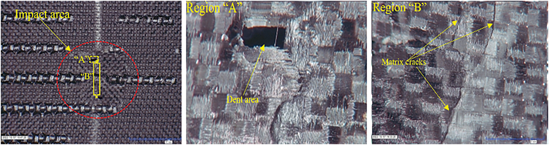
Figure 9: Damage patterns under 2 J energy impact
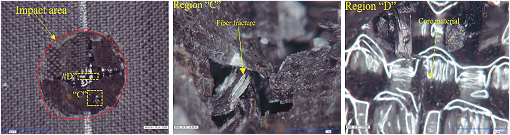
Figure 10: Damage patterns under 3 J energy impact
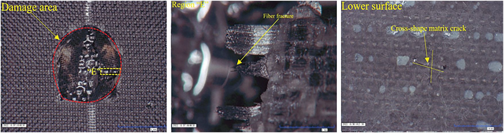
Figure 11: Damage patterns under 5 J energy impact
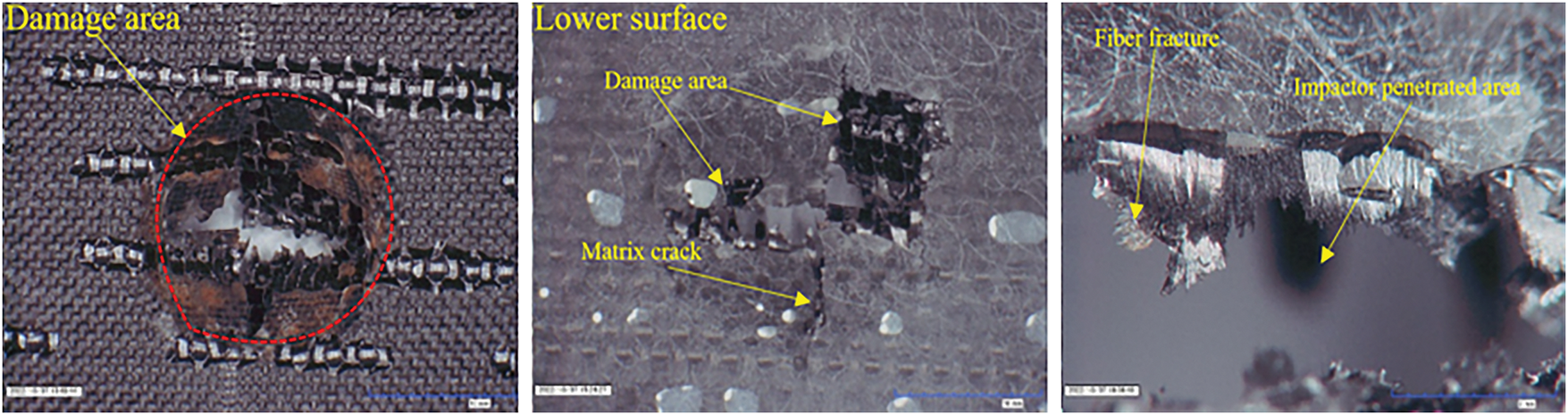
Figure 12: Damage patterns under 7 J energy impact
Fig. 9 shows that under the impact of 2 J energy, the specimen experiences only minor damage to the upper panel surface. Surface matrix cracking is observed along with slight damage to the in-plane fibers, indicating that the material undergoes initial deformation but does not experience significant failure. In other words, the impact primarily affects the upper panel, and the warp, weft, and pile yarns aligned with the impact direction absorbing most of the energy. The core material remains largely unaffected, indicating that at this low energy level, the composite structure is able to absorb the energy effectively without extensive damage propagation.
Fig. 10 indicates that the specimen’s upper panel experiences severe damage under the impact of 3 J energy. The fibers within the impact zone are completely fractured, leading to extensive matrix cracking in the affected region. The core material also shows partial damage, suggesting that the impact energy has started to propagate through the upper panel and reach the core, but the damage is still contained within the immediate impact area. The severity of damage in the upper panel is indicative of the material’s decreased resistance at this energy level, while the core remains partially intact. In summary, this material design helps to protect the lower panel, which remains largely unaffected at low energy levels.
Fig. 11 illustrates that the specimen’s upper panel sustains severe damage under a 5 J impact. The impact zone shows visible pits, with complete fracture of the fibers in the affected area. The damage is significant, indicating that the composite is nearing its failure threshold. The lower panel exhibits a cross-shaped crack, and the damage zone closely matches the impactor’s cross-section, signifying the extent of the impact’s effect on the material. Additionally, the core material shows substantial damage, with significant deformation and failure, indicating the high level of stress transferred through the core to the lower panel.
Fig. 12 reveals extensive damage to both the upper and lower panels of the specimen after a 7 J impact. The upper panel is fully penetrated, with visible pits forming at the impact site, indicating complete material failure. The lower panel exhibits a large cross-shaped crack, and the damage region closely aligns with the largest impactor’s cross-sectional area, highlighting the full extent of the damage. Moreover, the core material is completely fractured, underscoring the severe internal failure caused by the high-energy impact.
In summary, the failure patterns evolve at higher impact energy (5 or 7 J) Matrix cracks in the upper panel form a cross-shaped pattern, and the damage zone becomes nearly circular. This area is slightly larger than the largest impactor’s cross-section, with ring-shaped matrix cracks forming around the impact zone. As the upper panel is penetrated, the core material beneath it is fully crushed, leading to a complete breach. Finally the lower panel begins to exhibit fiber-matrix fractures under the continued impact load, mirroring the damage mode observed in the upper panel. This progression highlights the composite’s response to higher energy levels, with localized damage initially and more extensive damage to both the upper panel and core material at higher energy levels.
3.3 Residual Bending Performance after Impact
The results from the four-point bending tests are presented in Table 5. X-type specimens consistently show higher failure loads and maximum displacements compared to Y-type specimens after the same energy impact, suggesting that X-type 3D integrated woven spacer composites possess greater bending stiffness and strength. The extent of impact damage plays a crucial role in determining both stiffness and residual strength. The larger damage areas resulting from higher energy impacts lead to more reduction in the specimen’s residual strength.

The X-type’s dense warp-direction arrangement offers superior resistance to bending and is more effective to maintain its structural integrity under impact conditions. This arrangement provides uniform stiffness distribution, ensuring X-type specimens to retain more strength and bending capacity after being subjected to impact forces. In contrast, the Y-type specimens, with their periodic core material arrangement, are more prone to failure under bending loads. The periodic structure causes fluctuations in stiffness, leading to a higher susceptibility to local buckling in the midsection of the impacted Y-type specimens.
Specifically, the core material in Y-type composites, being arranged periodically along the warp direction, results in stress concentration and inconsistent stiffness distribution across the specimen. This combined with the existing impact damage makes the Y-type specimen more likely to develop cracks and fail earlier compared to the X-type specimen. Therefore, structural design is important in improving the bending performance and resistance to impact of 3D integrated woven spacer composites.
Despite the general trend that higher energy impacts lead to larger damage areas and smaller residual strength, WCX shows a higher failure load than WBX at the same energy level. This can be attributed to the dense warp-direction arrangement in WCX, which offers superior stress distribution, enabling it to maintain higher strength despite similar damage areas.
The fibers in the 3D integrated woven spacer composites exhibit strong tensile properties, as inferred from their performance in the impact tests. The residual strength and displacement observed in the bending tests suggest that the fibers are well-suited to handle tensile forces, contributing to the composite’s resilience. However, the compressive properties are inferred to be weaker, based on the damage patterns observed under impact loading. During higher-energy impacts, the upper panel crushing and fiber-matrix separation indicate lower resistance to compression, which aligns with typical behavior observed in similar woven composite structures. The observed damage mechanisms by Zhao et al. [41] also suggested these trends in the material’s mechanical behavior although direct tensile and compressive tests were not performed.
3.4 Failure Mechanism of Bending Test Specimens
Fig. 13 shows the states of various specimens at the time of failure during the four-point bending test. The failure modes of non-impacted specimens (WX and WY) after bending test are also included for comparisons.
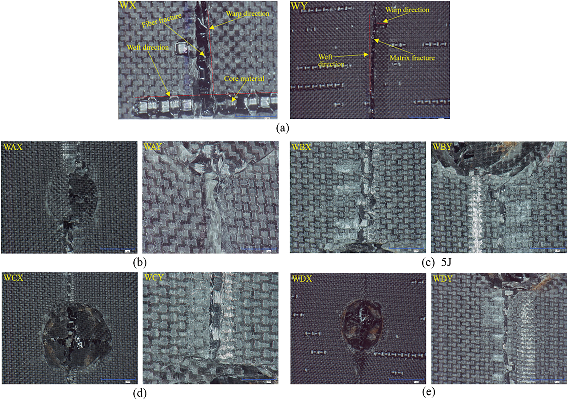
Figure 13: Failure modes in the bending test: (a) Impact-free, (b) 2 J, (c) 3 J, (d) 5 J, (e) 7 J
As the impact energy increases, the damage intensifies, leading to a noticeable decrease in the maximum displacement that the specimens can resist during the four-point bending test. For each specimen type, the failure mode primarily involves upper panel crushing and in-plane fiber fractures. This pattern suggests that the fibers in the 3D integrated woven spacer composites exhibit strong tensile properties but weaker compressive properties, leading to significant fiber fracture and material crushing under bending.
The 2 J energy impacted WAX and WAY specimens exhibit minor damage in the upper panel, primarily consisting of surface cracking and minor fiber breakage. The core material remains largely intact, allowing the specimens to retain most of their original bending strength and displacement capacity. The localized impact damage does not significantly affect the overall structural integrity, so these specimens maintain relatively high maximum displacement and bending stiffness. Although a slight decrease in stiffness is observed, the bending performance remains relatively unaffected compared to the non-impacted specimens (WX and WY).
The 3 J energy impacted WBX and WBY specimens sustain more extensive damage in the upper panel, including matrix cracking and fiber fractures in the impacted region. The core material begins to experience partial damage, reducing the material’s load-bearing capacity. Consequently, these specimens exhibit smaller maximum displacement compared to WX and WY specimens, as the damage impairs the composite’s ability to resist bending forces. The bending stiffness decreases and localized damage in the impacted area increases stress concentration, leading to more pronounced deformation during bending.
The 5 J energy impacted WCX and WCY specimens experience significant damage in the upper panel, including fiber breakage, matrix cracking, and crushing. The core material is severely damaged, hindering its ability to transfer loads between the upper and lower panels. The bending performance of these specimens weakens considerably, with much lower maximum displacement and stiffness compared to the previous specimens. The lower panel also begins to show early signs of failure due to the damage in the core material. Despite high energy absorption during the impact, the residual bending strength is significantly reduced due to the greater extent of damage to the core material and upper panel.
The 7 J energy impacted WDX and WDY specimens experience catastrophic failure. The lower panel undergoes extensive cracking and fiber-matrix fracture, while the upper panel is completely penetrated. The core material is severely crushed, resulting in a dramatic reduction in its load transfer ability. These specimens exhibit significant reduction in bending stiffness and only minimal displacement before failure. The extensive internal deterioration caused by the high-energy impact leads to a rapid failure of these specimens under bending load.
In general, X-type specimens show higher bending stiffness due to their uniform core material arrangement, which helps them resist bending forces more effectively. On the other hand, Y-type specimens, with their periodic core material arrangement, are more susceptible to localized buckling, which leads to early failure. Impact-induced damage plays a significant role in reducing the bending performance of these composites. Higher impact energies cause more extensive damage to the upper panel, core material, and lower panel, resulting in more decrease of bending strength and stiffness. Performance after impact can be further enhanced by improving the fiber-matrix bond and optimizing the core design.
This study investigates the impact behavior and residual bending properties of 3D integrated woven spacer composites under varying low-velocity impact energies. The main findings can be summarized as follows:
At the same impact energy, X-type specimens (warp direction) exhibited a higher maximum impact load and a smaller damage area compared to Y-type specimens (weft direction), indicating superior impact resistance for the X-type material. As the impact energy increased, the damage extended to the upper panel, core material and lower panel, with the Y-type specimens showing more extensive damage and lower residual bending strength.
Post-impact bending tests revealed that X-type specimens had higher flexural strength and stiffness, with maximum displacement and failure load significantly better than those of the Y-type specimens under identical impact conditions. The damage area increased with the impact energy, causing a corresponding decrease in residual bending strength, consistent with the general understanding that impact damage reduces the material’s ability to resist further deformation.
Test results suggest that X-type composites with a uniform core material arrangement offer enhanced performance under low-velocity impact and subsequent bending loads, making them suitable for applications requiring high energy absorption and load-bearing capacity. However, present study also indicates the need for further optimization of the core material design, as damage resistance could be improved by enhancing the fiber-matrix bond.
For practical applications, future studies should aim to increase the sample size to meet ASTM standards by testing three or more samples per test group. This would enhance the statistical confidence of the results and reduce the potential for uncertainty in comparing the directional impact resistance of the composite material. Besides, investigation should be made on the effects of varying face sheet thickness and core material configurations, such as multi-layer spacer composites. Multi-layer spacer composites could provide superior damage resistance and flexural performance, especially when combined with different core structures.
Acknowledgement: None.
Funding Statement: This research was funded by Open Foundation of the State Key Laboratory of Advanced Inorganic Fibers and Composites (Grant No. KF2024SYS02), the Jiangsu Province Special Fund for Carbon Peaking and Carbon Neutrality Technology Innovation (Grant No. BE2022008), and the Prioritized Academic Program Development for Higher Education Institutions in Jiangsu.
Author Contributions: The authors confirm contribution to the paper as follows: Conceptualization, Deng’an Cai; methodology, Mahim Masfikun Hannan; software, Mahim Masfikun Hannan; validation, Deng’an Cai and Xinwei Wang; formal analysis, Deng’an Cai; investigation, Mahim Masfikun Hannan and Deng’an Cai; resources, Deng’an Cai; data curation, Mahim Masfikun Hannan; writing—original draft preparation, Mahim Masfikun Hannan and Deng’an Cai; writing—review and editing, Deng’an Cai and Xinwei Wang; visualization, Mahim Masfikun Hannan; supervision, Deng’an Cai and Xinwei Wang; project administration, Deng’an Cai; funding acquisition, Deng’an Cai. All authors reviewed the results and approved the final version of the manuscript.
Availability of Data and Materials: The authors confirm that the data supporting the findings of this study are available within the article.
Ethics Approval: Not applicable.
Conflicts of Interest: The authors declare no conflicts of interest to report regarding the present study.
References
1. Mountasir A, Hoffmann G, Cherif C, Löser M, Großmann K. Competitive manufacturing of 3D thermoplastic composite panels based on multi-layered woven structures for lightweight engineering. Compos Struct. 2015;133(1–4):415–24. doi:10.1016/j.compstruct.2015.07.071. [Google Scholar] [CrossRef]
2. Kus A, Durgun I, Ertan R. Experimental study on the flexural properties of 3D integrated woven spacer composites at room and subzero temperatures. J Sandw Struct Mater. 2018;20(5):517–30. doi:10.1177/1099636216662925. [Google Scholar] [CrossRef]
3. Patekar V, Kale K. State of the art review on mechanical properties of sandwich composite structures. Polym Compos. 2022;43(9):5820–30. doi:10.1002/pc.26989. [Google Scholar] [CrossRef]
4. Zhang M, Wang X, Liu S, Li F, Wu G. Effects of face sheet structure on mechanical properties of 3D integrated woven spacer composites. Fibres Polym. 2020;21(7):1594–604. doi:10.1007/s12221-020-9908-6. [Google Scholar] [CrossRef]
5. Umair M, Ali Hamdani ST, Nawab Y, Asghar MA, Hussain T, Saouab A. Effect of pile height on the mechanical properties of 3D woven spacer composites. Fibres Polym. 2019;20(6):1258–65. doi:10.1007/s12221-019-8761-y. [Google Scholar] [CrossRef]
6. Azadian M, Hasani H, Shokrieh MM. Low velocity impact behavior of 3D hollow core sandwich composites produced with flat-knitted spacer fabrics. Fibres Polym. 2018;19(12):2581–9. doi:10.1007/s12221-018-8368-8. [Google Scholar] [CrossRef]
7. Zhou G, Liu C, Cai D, Li W, Wang X. Shear behavior of 3D woven hollow integrated sandwich composites: experimental, theoretical and numerical study. Appl Compos Mater. 2017;24(4):787–801. doi:10.1007/s10443-016-9552-x. [Google Scholar] [CrossRef]
8. Usta F, Türkmen HS, Scarpa F. Low-velocity impact resistance of composite sandwich panels with various types of auxetic and non-auxetic core structures. Thin Walled Struct. 2021;163(4):107738. doi:10.1016/j.tws.2021.107738. [Google Scholar] [CrossRef]
9. Kazemianfar B, Esmaeeli M, Nami MR. Response of 3D woven composites under low velocity impact with different impactor geometries. Aerosp Sci Technol. 2020;102:105849. doi:10.1016/j.ast.2020.105849. [Google Scholar] [CrossRef]
10. Dejene BK, Gudayu AD. Exploring the potential of 3D woven and knitted spacer fabrics in technical textiles: a critical review. J Ind Text. 2024;54(4):15280837241253614. doi:10.1177/15280837241253614. [Google Scholar] [CrossRef]
11. Sadighi M, Ahmad Hosseini S. Finite element simulation and experimental study on mechanical behavior of 3D woven glass fiber composite sandwich panels. Compos Part B Eng. 2013;55(3–4):158–66. doi:10.1016/j.compositesb.2013.06.030. [Google Scholar] [CrossRef]
12. Li DS, Jiang N, Jiang L, Zhao CQ. Static and dynamic mechanical behavior of 3D integrated woven spacer composites with thickened face sheets. Fibres Polym. 2016;17(3):460–8. doi:10.1007/s12221-016-5660-3. [Google Scholar] [CrossRef]
13. Peng J, Cai D, Zhang N, Zhou G. Experimental investigation on mechanical behavior of 3D integrated woven spacer composites under quasi-static indentation and compression after indentation: effect of indenter shapes. Thin Walled Struct. 2023;182(1):110213. doi:10.1016/j.tws.2022.110213. [Google Scholar] [CrossRef]
14. Li Y, Jin Y, Chang X, Shang Y, Cai DA. On low-velocity impact response and compression after impact of hybrid woven composite laminates. Coatings. 2024;14(8):986. doi:10.3390/coatings14080986. [Google Scholar] [CrossRef]
15. Vahedi N, Correia JR, Vassilopoulos AP, Keller T. Effects of core air gaps and steel inserts on thermomechanical response of GFRP-balsa sandwich panels subjected to fire. Compos Struct. 2023;313(2):116924. doi:10.1016/j.compstruct.2023.116924. [Google Scholar] [CrossRef]
16. Rahman MB, Zhu L. Low-velocity impact response on glass fiber reinforced 3D integrated woven spacer sandwich composites. Materials. 2022;15(6):2311. doi:10.3390/ma15062311. [Google Scholar] [PubMed] [CrossRef]
17. Cao D, Hu H, Wang Y, Li S. Experimental and numerical studies on influence of impact damage and simple bolt repair on compressive failure of composite laminates. Compos Struct. 2021;275(4):114491. doi:10.1016/j.compstruct.2021.114491. [Google Scholar] [CrossRef]
18. Rivallant S, Bouvet C, Hongkarnjanakul N. Failure analysis of CFRP laminates subjected to compression after impact: fe simulation using discrete interface elements. Compos Part A Appl Sci Manuf. 2013;55:83–93. doi:10.1016/j.compositesa.2013.08.003. [Google Scholar] [CrossRef]
19. Shah SZH, Megat-Yusoff PSM, Karuppanan S, Choudhry RS, Ud Din I, Othman AR, et al. Compression and buckling after impact response of resin-infused thermoplastic and thermoset 3D woven composites. Compos Part B Eng. 2021;207(12):108592. doi:10.1016/j.compositesb.2020.108592. [Google Scholar] [CrossRef]
20. Zhang Y, Gong Z, Pan E, Zhang C. A novel solution of rectangular composite laminates under oblique low-velocity impacts. Appl Math Mech. 2024;45(12):2165–82. doi:10.1007/s10483-024-3199-6. [Google Scholar] [CrossRef]
21. Hiremath S, Zhang Y, Kim TW. Low-velocity impact behavior in multi-layered structures and hybrid composites via sandwich stacking techniques. Polym Compos. 2024;45(8):7439–54. doi:10.1002/pc.28277. [Google Scholar] [CrossRef]
22. Zhu K, Zheng X, Sun J, Wang G, Yan L. Multi-point impact behavior and the relationship between CAI strength and DBIP of PMI foam sandwich structures. Chin J Aeronaut. 2024;37(10):265–74. doi:10.1016/j.cja.2024.07.028. [Google Scholar] [CrossRef]
23. Zhou J, Liu B, Wang S. Finite element analysis on impact response and damage mechanism of composite laminates under single and repeated low-velocity impact. Aerosp Sci Technol. 2022;129(16):107810. doi:10.1016/j.ast.2022.107810. [Google Scholar] [CrossRef]
24. Shiah YC, Tseng L, Hsu JC, Huang JH. Experimental characterization of an integrated sandwich composite using 3D woven fabrics as the core material. J Thermoplast Compos Mater. 2004;17(3):229–43. doi:10.1177/0892705704035410. [Google Scholar] [CrossRef]
25. Zhu L, Rahman MB, Wang Z. Effect of structural differences on the mechanical properties of 3D integrated woven spacer sandwich composites. Materials. 2021;14(15):4284. doi:10.3390/ma14154284. [Google Scholar] [PubMed] [CrossRef]
26. van Vuure AW, Ivens JA, Verpoest I. Mechanical properties of composite panels based on woven sandwich-fabric preforms. Compos Part A Appl Sci Manuf. 2000;31(7):671–80. doi:10.1016/S1359-835X(00)00017-8. [Google Scholar] [CrossRef]
27. Hosur MV, Abdullah M, Jeelani S. Manufacturing and low-velocity impact characterization of foam filled 3-D integrated core sandwich composites with hybrid face sheets. Compos Struct. 2005;69(2):167–81. doi:10.1016/j.compstruct.2004.06.008. [Google Scholar] [CrossRef]
28. Neje G, Behera BK. Comparative analysis of mechanical behavior of 3D woven spacer sandwich composites with single and double level structures. Polym Compos. 2020;41(11):4885–98. doi:10.1002/pc.25760. [Google Scholar] [CrossRef]
29. Chiu ST, Liou YY, Chang YC, Ong CL. Low velocity impact behavior of prestressed composite laminates. Mater Chem Phys. 1997;47(2–3):268–72. doi:10.1016/S0254-0584(97)80063-6. [Google Scholar] [CrossRef]
30. Hart KR, Chia PXL, Sheridan LE, Wetzel ED, Sottos NR, White SR. Comparison of compression-after-impact and flexure-after-impact protocols for 2D and 3D woven fiber-reinforced composites. Compos Part A Appl Sci Manuf. 2017;101(6):471–9. doi:10.1016/j.compositesa.2017.07.005. [Google Scholar] [CrossRef]
31. Ahmad Hosseini S, Sadighi M, Maleki Moghadam R. Low-velocity impact behavior of hollow core woven sandwich composite: experimental and numerical study. J Compos Mater. 2015;49(26):3285–95. doi:10.1177/0021998314561811. [Google Scholar] [CrossRef]
32. Castellanos AG, Prabhakar P. Elucidating the mechanisms of damage in foam core sandwich composites under impact loading and low temperatures. J Sandw Struct Mater. 2022;24(1):337–59. doi:10.1177/1099636221993848. [Google Scholar] [CrossRef]
33. Gao H, Li Y. Dynamic mechanical response evaluation of woven carbon fiber reinforced rubber laminated composites under high strain rates. Sci Rep. 2025;15(1):16711. doi:10.1038/s41598-025-01771-z. [Google Scholar] [PubMed] [CrossRef]
34. Junaedi H, Abd El-Baky MA, Awd Allah MM, Sebaey TA. Mechanical characteristics of sandwich structures with 3D-printed bio-inspired gyroid structure core and carbon fiber-reinforced polymer laminate face-sheet. Polymers. 2024;16(12):1698. doi:10.3390/polym16121698. [Google Scholar] [PubMed] [CrossRef]
35. Millen SLJ, Dahale M, Fisher T, Samy A, Thompson K, Ramaswamy K, et al. Modelling low-velocity impact damage and compression after impact of 3D woven structures considering compaction. Compos Struct. 2023;318:117104. doi:10.1016/j.compstruct.2023.117104. [Google Scholar] [CrossRef]
36. Zangana S, Epaarachchi J, Ferdous W, Leng J, Schubel P. Behaviour of continuous fibre composite sandwich core under low-velocity impact. Thin Walled Struct. 2021;158:107157. doi:10.1016/j.tws.2020.107157. [Google Scholar] [CrossRef]
37. Kazancı Z, Bathe KJ. Crushing and crashing of tubes with implicit time integration. Int J Impact Eng. 2012;42(4):80–8. doi:10.1016/j.ijimpeng.2011.10.003. [Google Scholar] [CrossRef]
38. Olhan S, Antil B, Behera BK. Low-velocity impact and quasi-static post-impact compression analysis of woven structural composites for automotive: influence of fibre types and architectural structures. Compos Struct. 2025;352:118676. doi:10.1016/j.compstruct.2024.118676. [Google Scholar] [CrossRef]
39. ASTM D7136/D7136M-15. Standard test method for measuring the damage resistance of a fiber-reinforced polymer matrix composite to a drop-weight impact event. West Conshohocken, PA, USA: ASTM; 2020. [Google Scholar]
40. ASTM D7264/D7264M-15. Standard test method for flexural properties of polymer matrix composite materials. West Conshohocken, PA, USA: American Society for Testing and Materials; 2021. [Google Scholar]
41. Zhao X, Ren H, Zhao J, Ouyang Y, Shi B, Liu Y. Mechanical properties and damage mechanism of 3D woven spacer composites improved with changing face layer structures: experimental and numerical study. Fibres Polym. 2024;25(6):2257–69. doi:10.1007/s12221-024-00562-z. [Google Scholar] [CrossRef]
Cite This Article
 Copyright © 2025 The Author(s). Published by Tech Science Press.
This work is licensed under a Creative Commons Attribution 4.0 International License , which permits unrestricted use, distribution, and reproduction in any medium, provided the original work is properly cited.
 Downloads
 Citation Tools