
 Submit a Paper
 Propose a Special lssue
 Open Access
ARTICLE

Experimental Investigation on the Strength and Ductility Performance of SteelTimber-Steel Joints with Screw and Steel-Tube Fasteners
College of Civil Engineering, Nanjing Tech University, Nanjing, 211816, China
* Corresponding Author: Benkai Shi. Email:
Journal of Renewable Materials 2023, 11(12), 4175-4195. https://doi.org/10.32604/jrm.2023.028507
Received 03 January 2023; Accepted 03 March 2023; Issue published 10 November 2023
 View Full Text
 Download PDF
Abstract
This article presents experimental results of steel-timber-steel (STS) joints loaded parallel to grain. Eight groups of specimens were designed, and tensile tests were performed. The fastener types and fastener numbers were considered to evaluate the tensile strengths and ductility performances of the STS joints. The screws with 6 mm diameter and the innovative steel-tubes with 18 mm diameter were adopted as connecting fasteners. The experimental results were discussed in terms of yielding and ultimate strengths, slip stiffness, and ductility factors. The ductility classification and failure mechanisms of each group of specimens were analyzed. It was demonstrated that the STS joint with large diameter steel-tubes showed acceptable ductility, which was close to the ductility of the STS joint with small diameter screws, thanks to the hollow structure of the steel-tube. The theoretical strengths of various failure modes for the joints with small diameter screws or large diameter steel-tubes were calculated and compared with the experimental results. The ductile performance of the STS joint was discussed by comparing the theoretical strengths of various failure modes. The effective number of the STS joint with multifasteners was also analyzed by considering the failure mechanisms in aspects of tensile strength and slip stiffness.Keywords
As the advantages of environmental protection, carbon sequestration, and the application of renewable materials, timber structures gained significant development in recent decades, and showed a good development prospect in the future. For all types of timber structural systems, timber joints are crucial to the mechanical behaviors of timber structures. The dowel-type joints are commonly used in timber frame structures, truss ones, and light wood frame construction. In past decades, many investigations about dowel-type joints have been carried out. The European Yield Model (EYM), which was developed based on the original research of Johansen [1], was cited by Eurocode 5 [2]. Also, many researchers extensively studied the mechanical behaviors and failure mechanisms of dowel-type joints considering the angle to the grain of timber [3–5]. The rotational performances of timber joints with dowel-type fasteners [6–8], and the embedment, as well as withdrawal behaviors of the dowel-type joint [9–12], were widely researched. These investigations greatly promoted the development of timber structures.
With the development of glulam technology, timber buildings showed great application prospects in multi-story and large-span construction areas. These developing tendencies put forward higher requirements for the mechanical properties of timber joints. Therefore, the reliability and failure mechanism of timber joints have received extensive attention [13].
EYMs introduce the typical ductile failure modes of timber joints, such as the embedment deformation of timber and the bending of metal dowels [14]. However, with the increase in the number and diameter of fasteners, the typical failure of dowel-type joints presented the characteristics of brittle failure. Quenneville et al. [15,16] researched the brittle failure of bolted timber joints loaded parallel and perpendicular to grain, and found that the 5th percentile ultimate load for the joints parallel to grain was 1.6 times that for the joints perpendicular to grain, on the precondition of same cross-section, dowel diameter, and timber strength. Stahl et al. [17] investigated the brittle failure of timber rivet joints, and found that the joint loaded parallel to grain occurred plug failure when decreasing the distances between rivets or decreasing the timber end and edge distances. It was also found that the STS joint loaded perpendicular to grain showed cracks extending along the grain from the top rivet row. Zarnani et al. [18] proposed a stiffness-based approach to evaluate the plug shear strength of timber rivet joints, and established the improved design procedure by distinguishing brittle failure modes and ductile failure modes of timber rivet joints. It was demonstrated that the improved procedure showed better predicting accuracies compared with the methods adopted by Eurocode 5 [2] and Stahl et al. [17].
Based on the researches above, various brittle failure modes for timber joints with large diameter dowel-type fasteners or small diameter screws were investigated. Jensen et al. [19] proposed a quasi-nonlinear fracture mechanics model for the row shear failure of dowelled joints loaded parallel to grain by considering the end distance and effective quantity of multiple fasteners in a row, and demonstrated its good accuracy by comparing with the test results of timber joints with one row or two rows of bolts. Meanwhile, Jensen et al. [20] found that the ultimate strength of the bolted connection was improved by about 100% when the loaded timber end length increased to 6d (d = 20 mm, the diameter of the bolt) from 3d, and increased by about 12% when the edge width increased to 80 mm from 40 mm on the precondition of 3d end length, and then presented the strength calculation method for the row shear failure of a single fastener joint by simultaneously considering the shear strength parallel to grain and the tensile strength perpendicular to grain. Schmid et al. [21] proposed a novelty calculation model for splitting and row shear failure based on the fracture mechanics and energy release rate by considering the end and edge distances, as well as the number and spacing of the dowels in a row. Wrzesniak et al. [22] found the load-carrying capacity of the timber joints with one row of bolts increased by 83.2%, and the failure modes turned to timber cross-section tensile failure from timber splitting when the end distance increased to 70 mm from 30 mm. Jockwer et al. [23] investigated the reliability of dowel-type joints combining the failure modes, and found that the brittle failure leads to a higher variability in load-carrying capacity, when the ductile failure leads to a lower variability. It was suggested that the variability could be reduced by applying the self-tapping screws to the loaded end of the timber joints. As to the plug shear failure of dowel-type joints with small diameter fasteners (about no greater than 6 mm [24]), Yurrita et al. [25] summarized the calculation models, which were proposed by Kangas et al. [26], Johnsson et al. [27], Stachl et al. [17], and Zarnani et al. [18], respectively. They compared the above models with the plug and block modes in Annex A of Eurocode 5 [2] and experimental results, and found that the models in Annex A of Eurocode 5 showed the best accuracy.
As summarized above, the ductile and brittle failures for both small diameter and large diameter dowel-type joints have been widely studied. However, several aspects need to be improved further. On the one hand, the critical relationship between ductile failure and brittle failure need to be analyzed. On the other hand, the brittle failures of dowel-type joints with small and large diameter fasteners were analyzed separately in most available investigations. However, their brittle failures exhibit potential similar characteristics, such as timber splitting failure and timber block shear failure. Their critical brittle strength needs to be verified by the existing models to evaluate the similarity of timber joints with small and large diameter fasteners. In addition, the methods to reinforce large diameter dowel-type joints were proposed, including self-tapping screw reinforcement [28,29], nail plate reinforcement [30], and glass fiber textile [31]. The ductility of the dowel-type joints was also improved to different extents. In this article, the innovative hollow steel-tube was adopted as the fastener aiming to improve the brittle failure of the STS joint with large diameter dowels.
This article presents the tensile tests performed on STS joints loaded parallel to grain. The small diameter screws and large diameter steel-tubes were adopted to evaluate the failure modes of STS joints with different diameter dowel-type fasteners. The tensile strength, slip stiffness, and ductile factors of the STS joints with screws and steel-tube were discussed based on load-slip curves. By comparing the EYMs with the various brittle failure strengths, the theoretical strengths to distinguish different failure modes were analyzed. Experimental results demonstrated that, thanks to the adoption of the hollow structure, the STS joint with steel-tubes showed the significant application to improve the ductility of the STS joints with large diameter dowel-type fasteners.
The timber used in this experimental programme was made of Douglas fir glulam from North America. According to EN 408 [32], the average compression strength and elastic modulus of the timber parallel to grain were tested as 29.6 MPa and 12270 N/mm2, respectively. The average tension strengths parallel and perpendicular to grain were tested as 47.8 and 1.2 MPa, respectively. The moisture content of the timber was tested as 15.8% in accordance with EN 13181-1 [33], and the corresponding average density was tested as 511 kg/m3.
Hexagon head wood screws were used in the STS joints. The screws were manufactured in accordance with DIN 571 [34]. As shown in Fig. 1, the nominal diameter and total length were 6 and 70 mm, respectively. According to ASTM F1575-17 [35], the average maximum bending moment and ultimate bending strength were tested as 7.9 × 10³ N⋅mm and 219.3 MPa, respectively, on the precondition of the 30 mm supporting spacing. According to EN 1382 [36], the nail-holding ability parallel and perpendicular to the grain were tested as 5.87 and 7.30 kN, respectively.
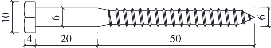
Figure 1: Dimensions of the screw (dimensions in mm)
The steel-plate and steel-tube adopted in the STS joints were made of S235 steel. As shown in Fig. 2, the diameter and wall thickness of the steel-tube were 18 and 4 mm, respectively. The average ultimate bending moment and bending strength of the steel-tube were tested as 4.2 × 10⁵ N⋅mm and 386.3 MPa, respectively, by referring to ASTM F1575-17 [35]. According to ISO 6892 [37], the average yielding and ultimate tensile strength of the steel-tube were tested as 340 and 411 MPa, respectively.
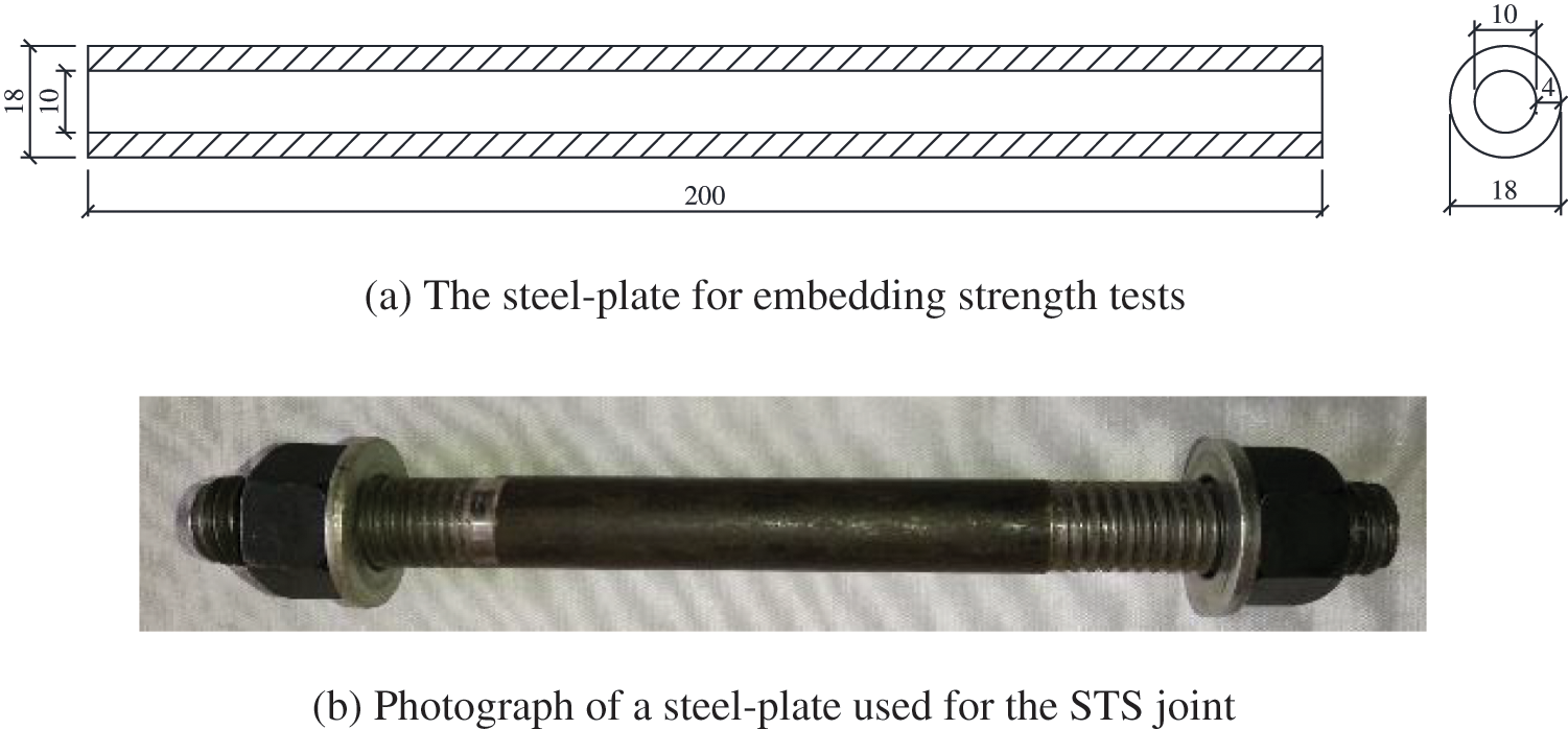
Figure 2: Steel-tube (dimensions in mm)
The embedment strength of the timber was determined according to ASTM D5764-97a [38]. As shown in Fig. 3a, the full hole configuration was adopted considering the actual stress in STS joints. The cross-section of the sample was 100 mm × 100 mm, while the length of the loaded end was 100 mm and the length of the unloaded end was 90 mm. The load-displacement curves are shown in Fig. 3b. The average yield load was determined as 28.1 kN by offsetting the proportional limit line by a deformation equal to 5% of the steel-tube diameter [38]. The average embedment strength of the timber was calculated as 15.6 MPa, and the embedment stiffness was 243.6 N/mm2.
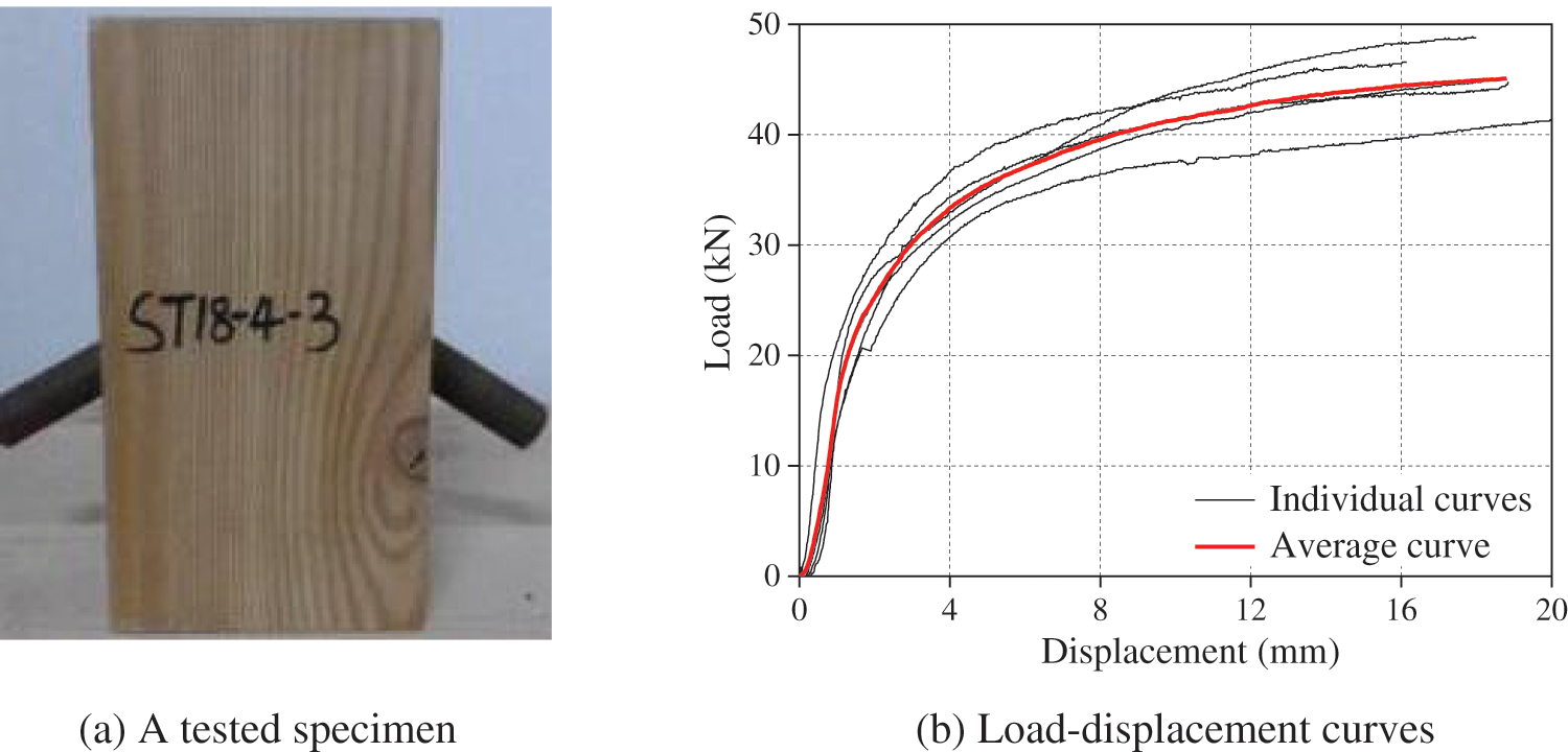
Figure 3: Embedment strength tests using the steel-tube
2.2.1 Design of STS Joint Specimens
The grouping and geometry dimensions of STS joint specimens are shown in Table 1 and Fig. 4, respectively. As shown in Table 1, four groups of specimens were designed for the timber joints with screws and steel-tubes. Six samples were prepared for each group. The specimen SPi (i = 1, 2, 4, and 8) means the steel-plate was connected to the timber block by i pairs of screws. Similarly, STi (i = 1, 2, 3, and 6) series specimens mean the steel-plate was connected to the timber block by i steel-tubes. The diameter of the screw and steel-tube were 6 and 18 mm, respectively, which were considered as the small and large diameter fasteners, respectively, referring to the existing investigations [24,25].
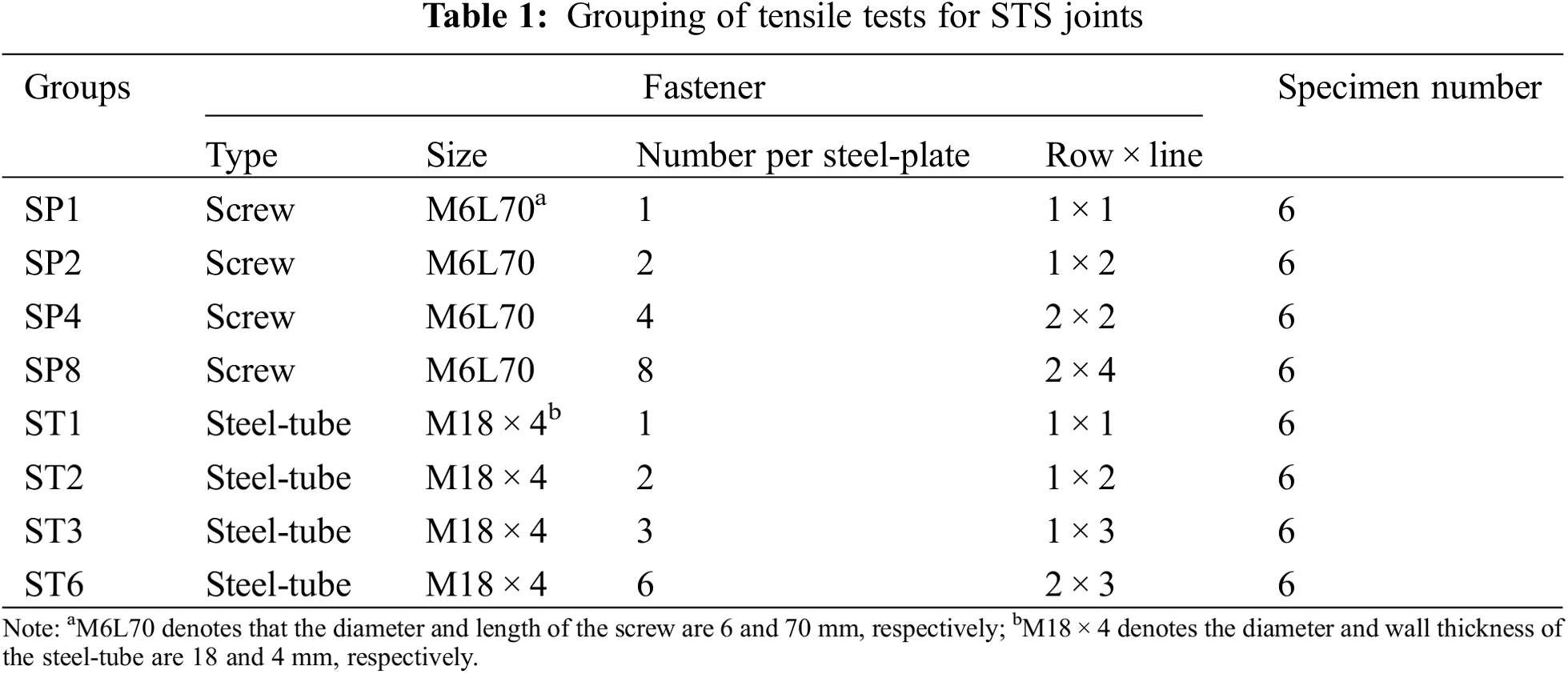
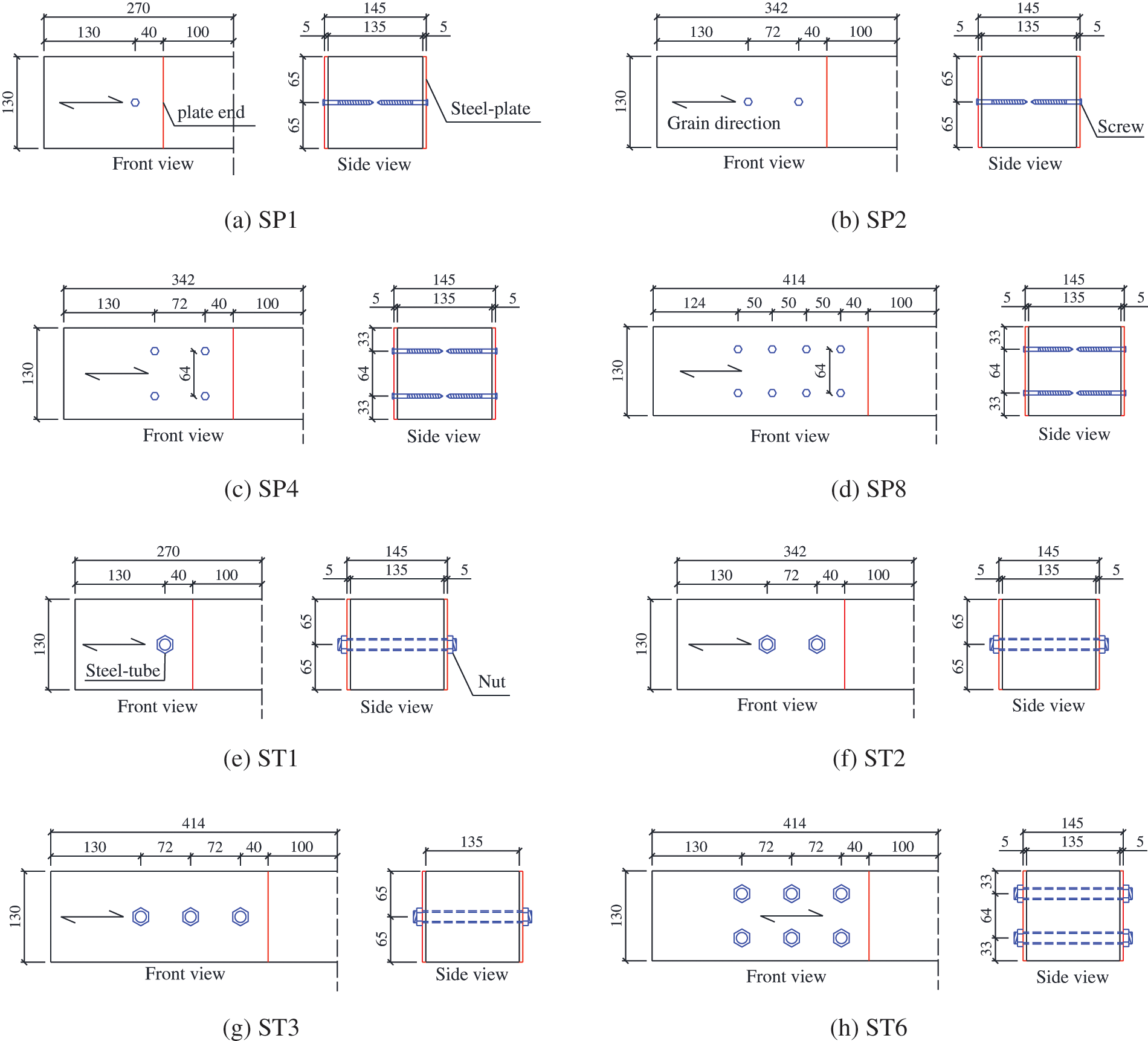
Figure 4: Dimensions of the half of STS joints with screws (SPi) and steel-tube fasteners (STi)
The symmetrical tension specimens were designed. The diagram for the half of each STS joint is shown in Fig. 4. The across-section of the timber block was 135 mm × 130 mm. The thickness of the steel-plate was 5 mm. The spacing perpendicular to grain between two rows was 64 mm, as shown in Figs. 4c, 4d, 4h. The M6L70 screws were drilled into the timber without the predrilled hole. The predrilled hole for the steel-tube was 19 mm in diameter. For the STS specimens with steel-tubes, a pair of nuts were used to work with the steel-tubes so as to fasten the steel-plate to the timber. The pre-tightening forces were not recorded when fabricating the ST series specimens. This is because the diameter of the predrilled hole (19 mm) was larger than that of the steel-tube. It was estimated that pre-tightening force has a slight influence on the load-carrying capacity of the ST series specimens.
The testing device for tensile tests is shown in Fig. 5. Both the upper end and bottom end of the tested specimens were measured during tests. Four linear voltage displacement transducers (LVDTs) were used to record the interfacial relative slip between the steel-plate and the timber at each end. The interfacial relative slip of the specimen at the upper end was determined as the average value of LVDTs P1∼P4, while that of the specimen at the bottom end was determined as the average value of LVDTs P5∼P8. The tensile tests were conducted under the displacement-control mode with a constant loading rate of 0.2 mm/min. The testing load was determined as the force transmitted from the actuator, which was recorded by the control system of the actuator. The specimens sustained the testing load until the specimens were broken.
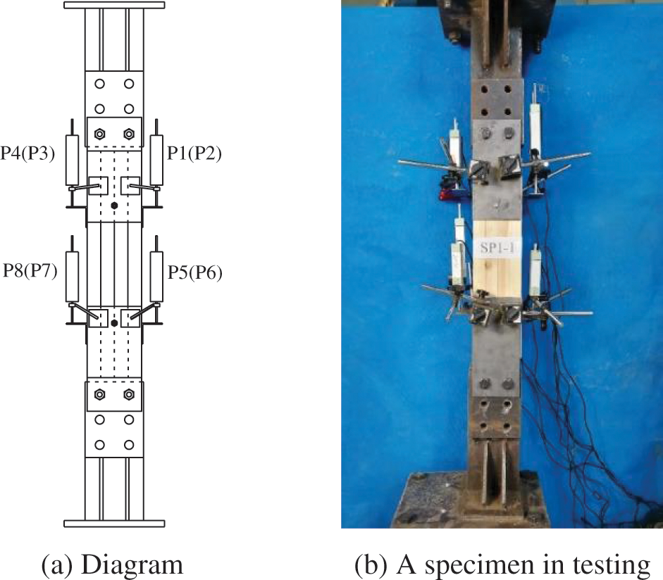
Figure 5: Tensile testing device
Fig. 6 shows the typical failure modes of the STS specimens with screws. Most SP series specimens showed the screw yielding and the embedding failure of the timber, as shown in Figs. 6a, 6c, 6d. As shown in Figs. 6b, 6e, some screws were pulled out from the timber, coupled with severe bending deformation. As shown in Figs. 6c, 6d, the screws showed shear failure, which occurred at the conversion surface between the circular part and the threaded part. With the increase in the number of screws, the SP series specimens showed the evident splitting failure (SP8 specimens) of the timber as shown in Figs 6e, 6f, which was obviously distinct from other STS joint specimens with screws.
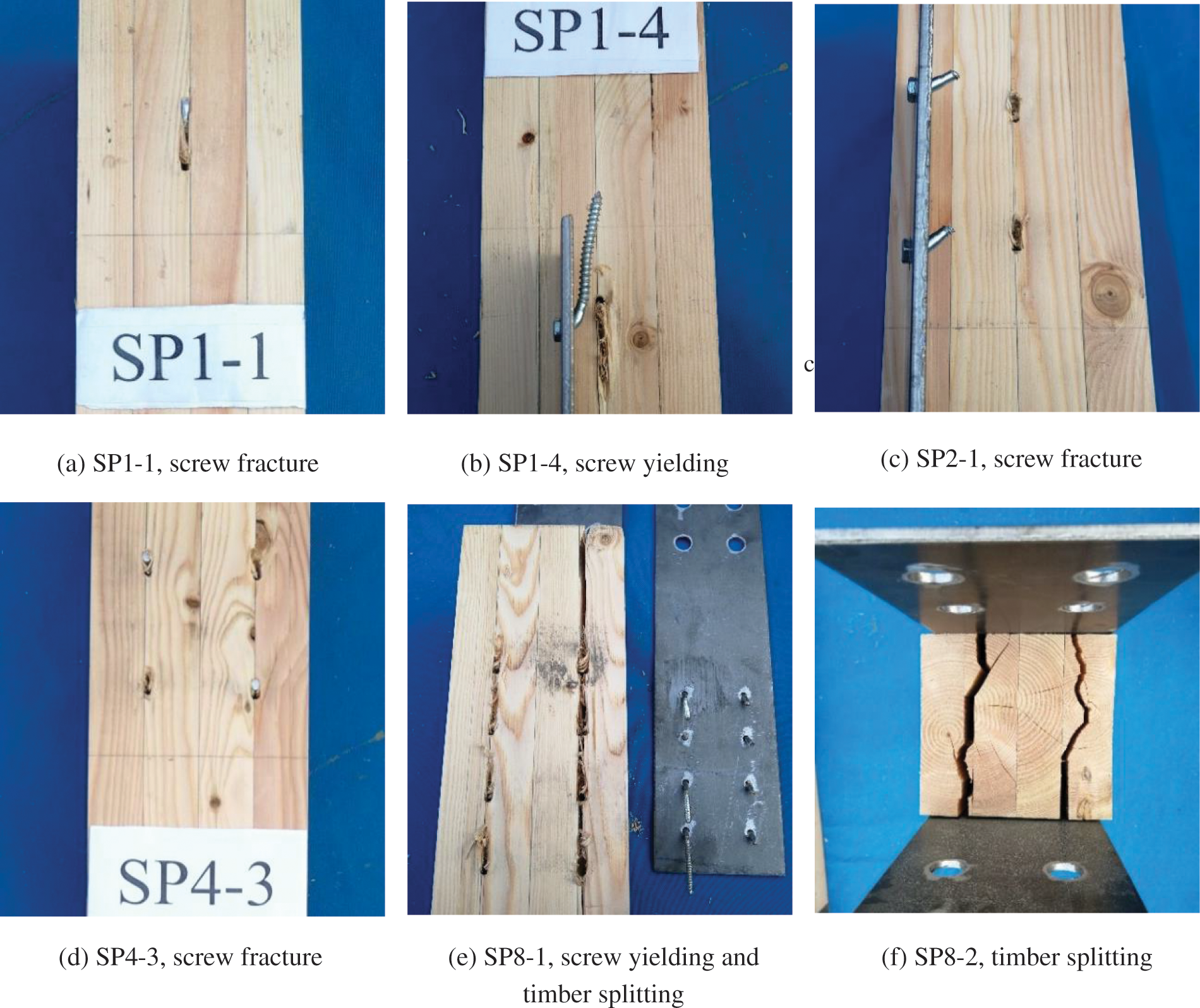
Figure 6: Failure photographs of STS specimens with small diameter screws
Fig. 7 shows the typical failure modes of the STS specimens with steel-tubes. The ST series specimens with steel-tubes also showed the steel-tube yielding, timber embedding failure, as well as timber splitting and row shear failures. The steel-tube occurred plastic bending deformation and shear fracture, as shown in Figs. 7a, 7c. For the specimens with one or two steel-tubes, the timber occurred obvious splitting failure, as shown in Figs. 7b, 7c. In Fig. 7d, specimen ST2-6 showed severe timber splitting, which was close to the row shear failure of the timber. With the increase in the number of steel-tube, the timber embedding deformation declined, as shown in Fig. 7e, coupled with the appearance of timber splitting failure. From Figs. 7f–7i, ST specimens with 3 and 6 steel-tubes occurred the row shear failure of the timber. Some specimens were characterized by the mixed failure mode, including the timber row shear failure among the spacing of the steel-tubes and the timber splitting failure at the loaded end, such as the specimen ST3-2 shown in Fig. 7f.
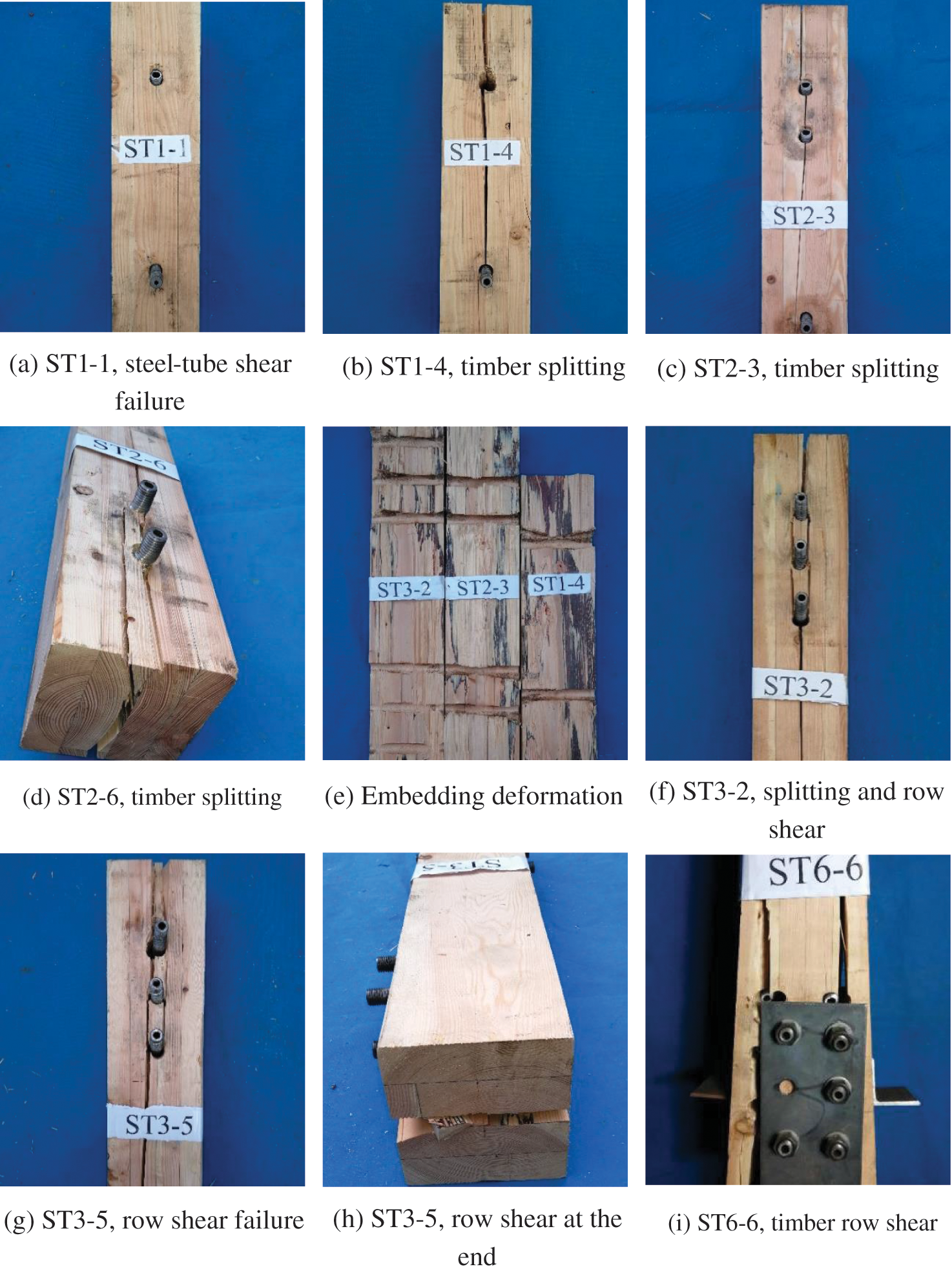
Figure 7: Failure photographs of STS specimens with large diameter steel-tubes
The load-slip curves of the STS specimens with screws and steel-tubes are displayed in Figs. 8 and 9, respectively. The local magnification portions of load-slip curves at the initial loading stage are also shown in Figs. 8 and 9. The ‘-i’ (i = 1∼6) at the curve label denotes the specimen number, while ‘U’ and ‘B’ mean the measurement point at the upper end and bottom end of the specimen, respectively.
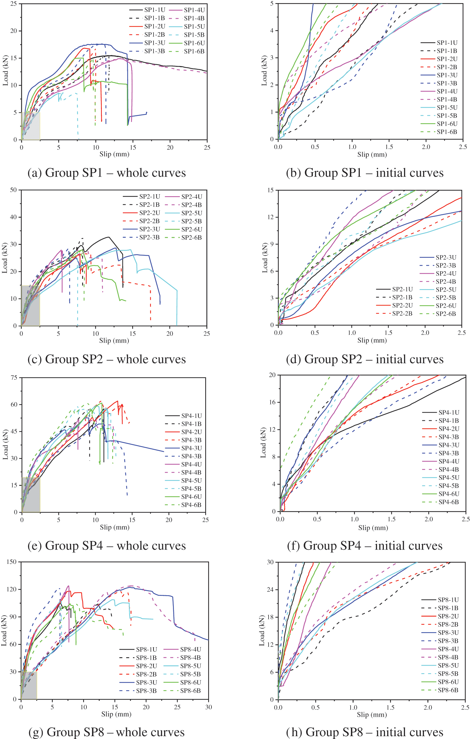
Figure 8: Load-slip curves of STS joints with screws
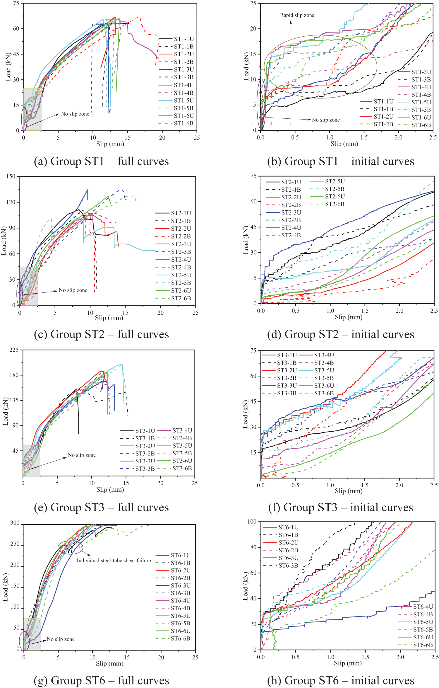
Figure 9: Load-slip curves of STS joints with steel-tubes
Analyzing Fig. 8, the following results are summarized: (i) The STS joint with screws showed an evident initial elastic stage, the followed yielding stage caused by the screw bending and the timber embedding deformation, as well as the secondary hardening stage caused by the ‘rope effect’ of the screws. (ii) As shown in the local amplification curves, the load-slip curves show a slight non-slip zone at the initial slip stage. In the non-slip zone, the maximum load per pair of screws is approximately 0.5∼1.0 kN, which was caused by the pre-tightening force when drilling the screw into the timber.
Compared with the ST series specimens, the curves of SP series ones shown in Fig. 9 displayed evident differences in the following aspects: (i) Bigger non-slip zone can be observed for all ST specimens. In the non-slip zone, the associated maximum load per steel-tube was approximately 5.0∼10.0 kN. The pre-tightening force transmitted from nuts caused the bigger non-slip zone. (ii) The ST series specimens showed a rapid slip stage after the non-slip zone, which was caused by the gapping between the timber and steel-tube after the failure of friction between the steel-plate and the timber. (iii) The load-slip curves for ST series specimens showed the sudden fracture when the testing load reached the maximum value, which is consistent with the failure modes of timber splitting failure and row shear failure shown in Fig. 7.
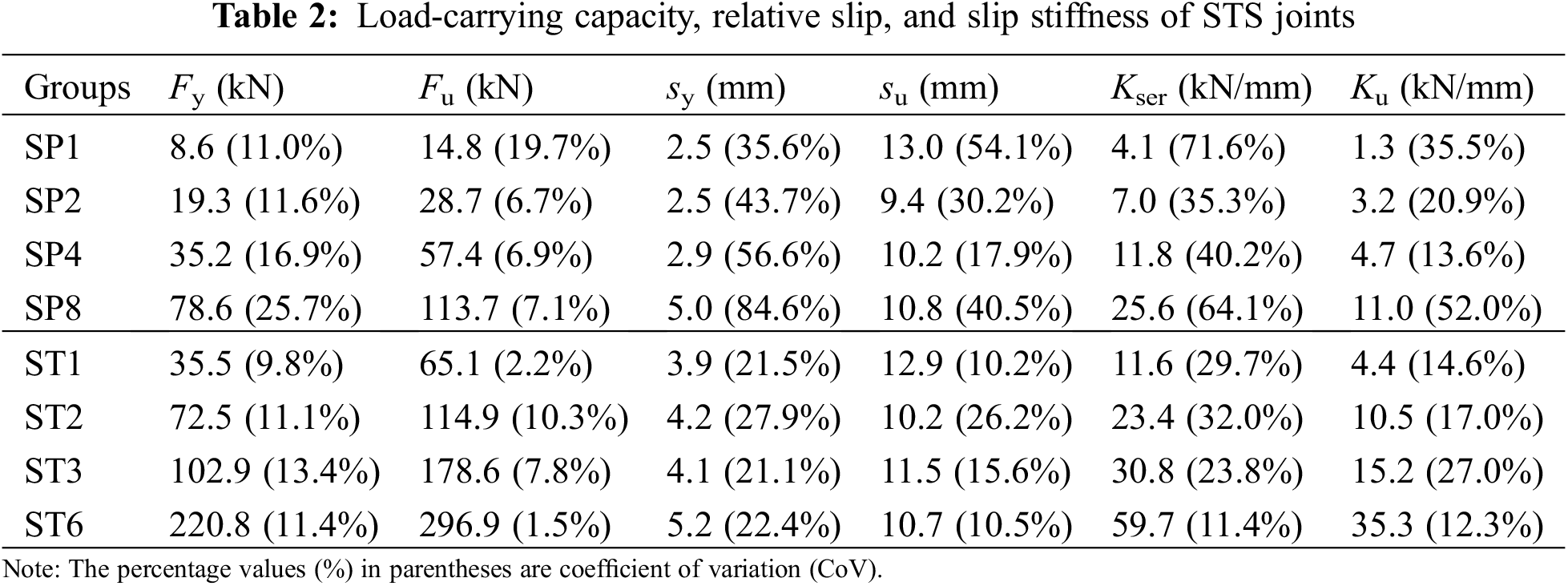
2.3.3 Strength and Slip Stiffness
The testing results are summarized in Table 2. The maximum testing load was determined as the ultimate capacity (Fu) of the specimen. The yield load Fy was determined according to EN 12512 [39]. Kser and Ku denote the slip stiffness of the joint at the serviceability limit state and ultimate state, respectively. By referring to EN 26891 [40], the secant stiffness was adopted to determine the values of Kser and Ku, which were defined in Eqs. (1) and (2), respectively. The similar simplified method to evaluate the slip moduli of steel-to-timber joints was also adopted in the available research [41].
where,
Valuable conclusions can be obtained from Table 2: (i) The average ultimate bearing capacity of the specimens with one pair of screws was 14.8 kN, while that of those with one steel-tube was 65.1 kN. (ii) For both SP and ST series specimens, the ultimate bearing capacity Fu was basically proportional to the number of fasteners. The ultimate bearing capacities of SP2, SP4, and SP8 are 1.9, 3.9, and 7.7 times that of SP1, respectively. The yield load Fy also basically conforms to this rule. (iii) Compared with Fy, Fu, and su, the yield deformation sy showed higher values in CoV. This phenomenon may be caused by the large individual differences in pre-tightening force levels. (iv) The Kser of the specimens in group ST1 reached to 11.6 kN/mm, which was equivalent to that of SP4 specimens with four pairs of screws. (v) For the STS joints with screws, the values of Ku were about 32%∼46% of those of Kser due to the severe yielding of small diameter screws. As comparisons, the values of Ku were approximately 50% of those of Kser for the STS joints with large diameter steel-tubes.
3.1 Ductility Factors and Failure Modes
The ductility factors of the STS joint can be calculated by Eq. (3) according to EN 12512 [39]. The calculation results of ductility factors are listed in Table 3. According to the report of Brühl et al. [42], the ductility of timber structure joints can be classified as brittle (D ≤ 2), low ductility (2 < D ≤ 4), moderate ductility (4 < D ≤ 6), and high ductility (D > 6). The failure modes were also summarized in Table 3. The abbreviations of failure modes in Table 3 are explained as follows, combined with the graphic illustration in Fig. 10:
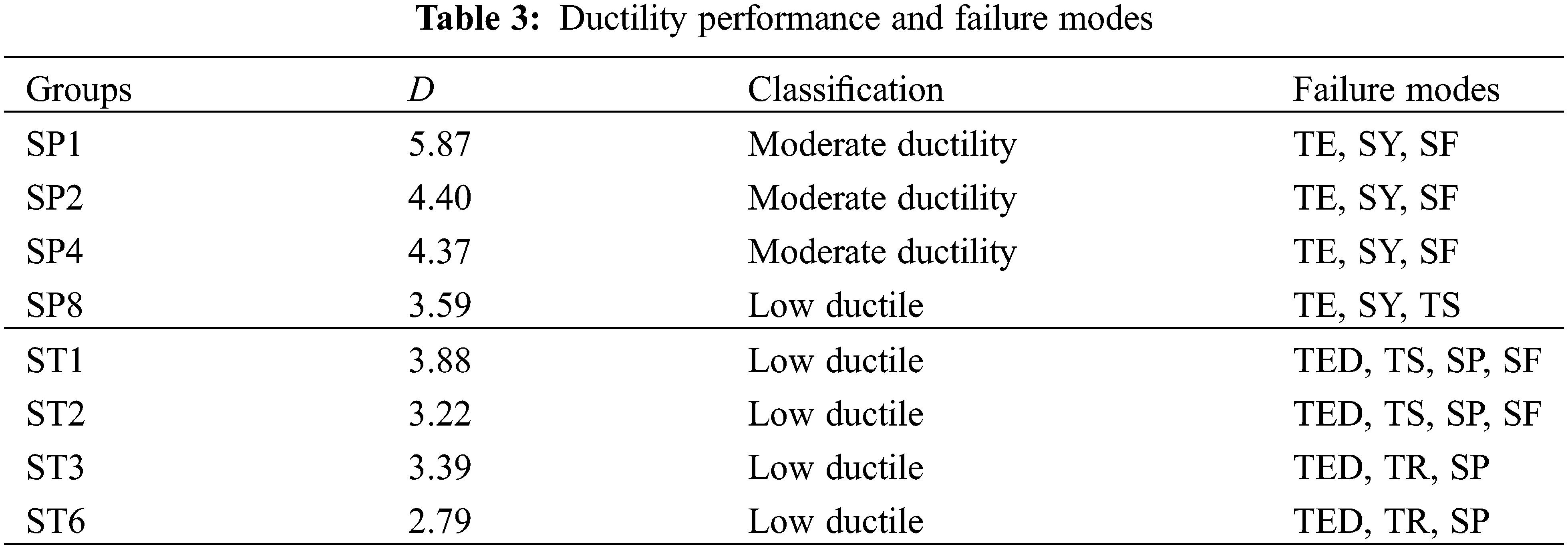
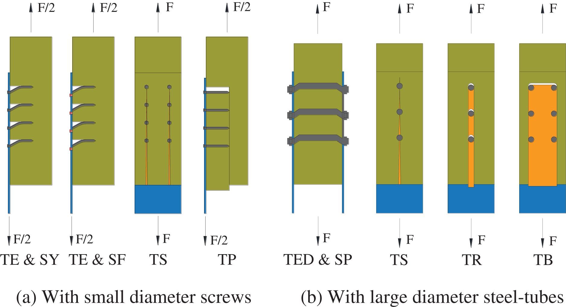
Figure 10: Typical failure modes for STS joints
TE, serious timber embedding failure;
SY, screw yielding;
SF, shear failure of fasteners (screws or steel-tube);
TS, timber splitting failure;
TED, timber embedding deformation;
SP, plastic hinge of steel-tube;
TR, timber row shear failure.
As shown in Table 3, for both SP and ST series specimens, the ductility factor basically declined with the increase of the fastener number. SP1 specimens were close to a critical value of high ductility failure (D > 6). SP8 specimens were classified as low ductility, which was consistent with the appearance of timber splitting failure. ST series specimens showed ductility factors ranging from 2 to 4, and were classified as low ductility. It can be found that the ductility factors of ST1, ST2, and ST3 specimens are close to those of SP series specimens. As shown in Fig. 7, the steel-tube showed obvious compressional deformation, which increased the relative slip and improved the ductility of the STS joints with large diameter fasteners.
The mixed failure modes summarized in Table 3 also can be observed in Figs. 6 and 7. For the groups classified as having low ductile failure, the specimens tested always showed the mixed failure modes of ductile failure (TE, SY, and SP) and brittle failure (TS and TR). Apparently, before the specimens occurred brittle failure, the ductility failure characteristics were also observed in the specimens. In addition, Fig. 10 also depicted another two typical brittle failures, i.e., timber plug shear (TP) and timber block shear (TB), which were not observed in the experimental programme, whereas they will also be analyzed in Section 3.2.
3.2 Strength Models for Various Failure Modes
The load-carrying capacities with various failure modes were introduced in Eurocode 5 [2] based on the EYMs (Chapter 8) and the timber shear failure (Annex A). The theoretical methods in EYMs are sufficient to predict the strengths of various ductile failure modes for STS joints. However, the brittle failure modes have become the research focus in recent years. Therefore, the available investigations explored the failure strengths of possible brittle failure modes of STS joints, such as timber plug shear failure, block shear failure, splitting failure, row shear failure, and timber tensile failure.
The shear failure of the fastener was observed in both SP and ST series specimens. The shear strength of the metal fastener can be estimated by Eq. (1). For the STS joint with steel-tubes, the hollow ratio should be taken into consideration when calculating the cross-section of the steel-tube.
where, As is the cross-section area of the fastener (mm), fss is the shear strength of the screws or steel-tube (N/mm2).
3.2.2 Mixed Failures of Dowel Plastic Deformation and Timber Embedment
Based on the EYM method, the tensile strength of the joint with mixed failures can be calculated by Eq. (5), in which the double plastic hinge model was considered. Yurrita et al. [43] found that the model of EYM provided a conservative result by comparing with experimental results, and then proposed the correction factor as shown in Eq. (6).
where, My is the bending moment capacity of the metal fastener (N⋅mm), fh is the embedment strength of the timber parallel to grain (N/mm2), d is the diameter of the fastener (mm), Fax is the withdrawal capacity of the fastener (N), which is ignored for the specimens connected with steel-tubes.
3.2.3 Timber Splitting Failure
The timber splitting failure was not considered in the Eurocode 5 [2]. In recent years, Jorissen [44] and Jensen et al. [20] proposed splitting failure modes based on fracture energy. However, the calculation of the two models above relies on the determination of the fracture energy parameter. Jockwer et al. [23] proposed the calculation model for timber splitting failure based on the timber tensile strength perpendicular to the grain. This model proposed by Jockwer et al. [23] only considered the end distance of the timber as shown in Eq. (7).
where, t is the thickness of the timber (mm), ae is the end distance of the splitting failure (mm), as shown in Fig. 11; ft,90 is the tensile strength of the timber perpendicular to grain (N/mm2).
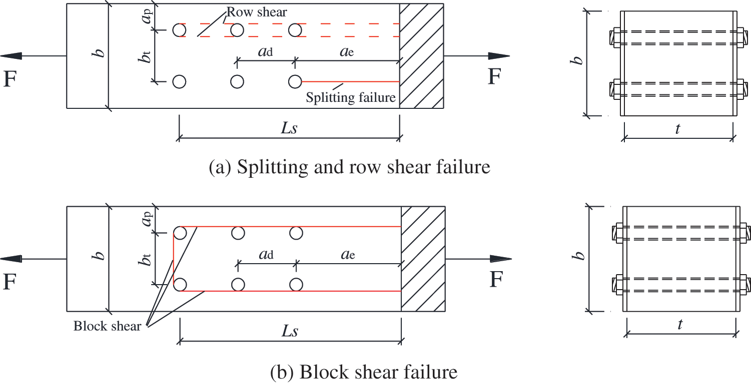
Figure 11: Symbols used for parametric calculation
Yurrita et al. [45] proposed a calculation method for the timber splitting failure mode of the STS joint with one row of fasteners by considering the effective thickness and net length in splitting, as shown in Eq. (8).
where, lef is the effective length of the potential splitting plane, which can be calculated by Eq. (9). tef is the effective thickness of the potential splitting plane. Yurrita et al. [46] provided the sufficient analysis based on the elastic foundation model to determine the effective thickness. By referring to the work of Yurrita et al. [46], the effective thicknesses tef for the STS joint with small diameter screw and large diameter dowels (steel-tube) were determined as 0.6t and 1.0t, respectively.
where, ad is the spacing distance between the fasteners (mm); ae is the end distance (mm), n is the number of the fastener in a row, d0 is the diameter of the pre-drilling hole (mm). The diagram of the above parameters is shown in Fig. 11.
3.2.4 Timber Row Shear Failure
The timber row shear failure was also not considered in the Eurocode 5 [2]. This failure mode mainly occurred in the STS joint with large diameter dowels. Jorissen [44] proposed the strength model for the timber row shear failure based on fracture mechanics. This model relies on the determination of the fracture energy and friction angle, and shows certain limitations in applications. Therefore, Quenneville [24] and Yurrita et al. [47] proposed the timber row shear strength model based on the shear strength of the timber parallel to grain, which is shown in Eq. (10).
where, ks is the coefficient considering the stress distribution, which was determined as 0.75 by Quenneville [24] or by the equation of
3.2.5 Timber Plug Shear and Block Shear Failure
The timber block shear and plug shear failures were described in Annex A of Eurocode 5 [2]. Also, many improved calculation models were provided by considering different methods for the definition of the potential failure planes [17,18,25]. In this article, due to the design of a symmetrical steel-timber-steel configuration, only the potential block shear failure is considered in the theoretical analysis. Additionally, the net tension failure, which was regarded as the typical brittle failure in available investigations [47,48], was not considered due to the relatively large net width and thickness of the timber block in tensile specimens. According to the Annex A of Eurocode 5 [2], the timber block shear strength of the STS joint can be calculated as the maximum value between the head tension with the width of bt and the lateral shear planes, as shown in Eq. (11).
where, At = btt is the effective area of the tensile plane (mm2); ft,0 is the tensile strength of the timber parallel to grain (kN/mm2).
Yurrita et al. [47] proposed a new design model for the timber block shear failure. Both the two lateral shear planes and the tensile one were considered to provide the shear resistance. Therefore, the prediction model can be expressed by Eq. (12),
3.3 Ductility Analysis Based on Tension Strengths
The comparisons between experimental results of tension strengths and predicted strengths of associated failure modes are depicted in Fig. 12. It can be found the ductility behavior can be determined on the basis of the theoretical prediction result of each potential failure mode, which agrees well with the actual failure modes observed in tensile tests. For the STS joints with small diameter screws, the main discussions are summarized, as follows:
i) All groups of SP series specimens showed screw shear failure and timber embedment failure, as shown in Fig. 6. However, the experimental strengths were significantly higher than the theoretical strengths of failure modes R0 and RI. The interfacial friction and pre-tightening force were ignored in Eqs. (4), (5). In addition, the full-hole set-up was adopted in embedment tests as shown in Fig. 3, which may underestimate the embedment strength of the timber due to the bending of the steel-tube. These factors caused the theoretical strengths of R0 and RI to be smaller than the experimental strengths.
ii) The specimens in group SP8 also displayed the additional timber splitting failure in Fig. 6. The experimental strength of group SP8 was between the theoretical results of failure modes R0 and RII,Y, which conforms to the experimental phenomena occurring in tensile tests, in which the timber splitting failure and typical European yield models (timber embedment and screw yielding) were observed as shown in Fig. 6. This result means that the ductility behavior of the STS joints can be predicted by comparing the theoretical strengths of the timber splitting failure and the joint ductile failures.
iii) For the timber splitting failure of the STS joint with small diameter screws, the RII,Y model proposed by Yurrita et al. [45] showed better accuracy than the RII,J model suggested by Jockwer et al. [23].
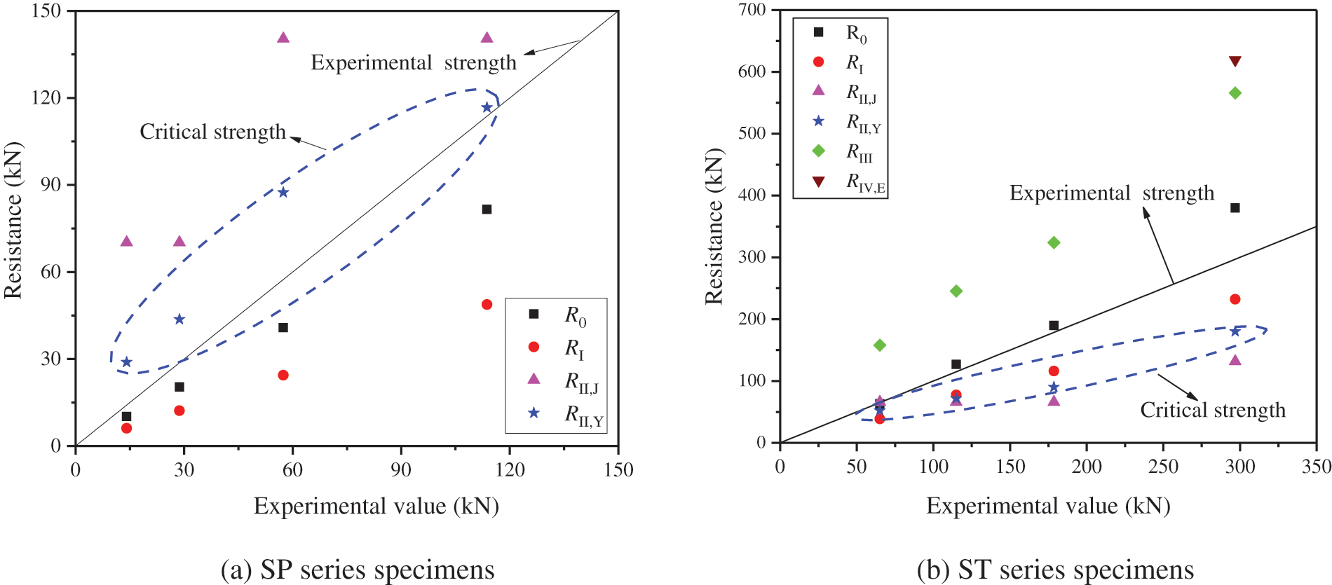
Figure 12: Comparisons between experimental results and model prediction strengths
For the STS joints with large diameter steel-tubes, the main conclusions are summarized from Fig. 12b as follows:
i) For ST1, ST2, and ST3 specimens, the experimental results of the tensile strength were between the theoretical strengths of the timber splitting failure (RII,Y) and steel-tube shear (R0) failure. These failure modes were also observed in tensile tests shown in Figs. 7a–7d.
ii) The resistance of failure mode RI is slightly bigger than that of failure mode RII,Y, which agrees well with the timber embedment deformation extent by comparing ST1 and ST3 specimens shown in Fig. 7e. Due to that the resistance of failure mode RI was bigger than that of failure mode RII,Y for ST3 specimens, and its timber embedment deformation did not reach to the extreme deformation state.
iii) The ST3 and ST6 specimens mainly exhibited the mixed failure of the timber splitting failure (RII,Y) and row shear failure (RIII), while the experimental strengths were located at the theoretical strength ranges between RII,Y and RIII. However, the row shear strengths are obviously bigger than the experimental tensile strengths of ST3 and ST6. Therefore, the effective spacing (Ls) in Eq. (10) may be overestimated.
iv) The timber block shear resistance of failure mode RIV,Y was 847.7 kN, which was not shown in Fig. 12b due to the bigger evaluation results than RIV,E calculated by Eq. (11). Therefore, ST6 specimens did not occur block shear failure thanks to the sufficient timber block shear strength compared with the resistances of timber splitting and row shear failures.
v) The shear strength of the steel dowel can be decreased by adopting hollow steel-tubes. The failure modes can be effectively controlled by comparing the resistances of R0 and RII,Y. Therefore, due to the application of steel-tubes, the ductility performance of the STS joint with large diameter dowel-type fasteners can be improved by optimizing the wall thickness of steel-tube.
It can be found from Fig. 12 that the STS joint may occur brittle failure while the timber splitting strengths are smaller than the strengths of the typical ductile failure modes. The typical ductile failure modes suggested in this study include the bending yielding (or shear) failure of the metal dowel and EYM failure modes. In the meantime, the timber splitting, row shear, block shear, and tension failures were listed as brittle failures. Therefore, the method to distinguish the ductile and brittle failures of the STS joint with both small and large diameter dowel fasteners can be approximately determined based on the strengths of each failure mode as shown in Eq. (13).
where, R0s and R0b are the shear and bending strengths of dowels, respectively; RI,E includes all the potential ductile failure of EYMs adopted in Chapter 8 in Eurocode 5 [2]; RII, RIII, and RIV are the strengths of timber splitting, row shear, and block shear failures, respectively.
3.4 Group Effects for Strength and Slip Stiffness
For the steel-timber joints with multi-fasteners, the tensile strength of the joint may be smaller than the sum of the resistance of each dowel. Therefore, Eurocode 5 [2] stipulates the effective number of fasteners, as shown in Eq. (14) (bolts and dowels) and Eq. (15) (screws). As shown in Table 2, it can be found that with the increase in the number of screws and steel-tubes, the total strength and slip stiffness increased correspondingly. To evaluate the group effect on the mechanical behavior of the multi-dowels joint, the average strength and stiffness per pair of screws or per steel-tube are plotted in Fig. 13.
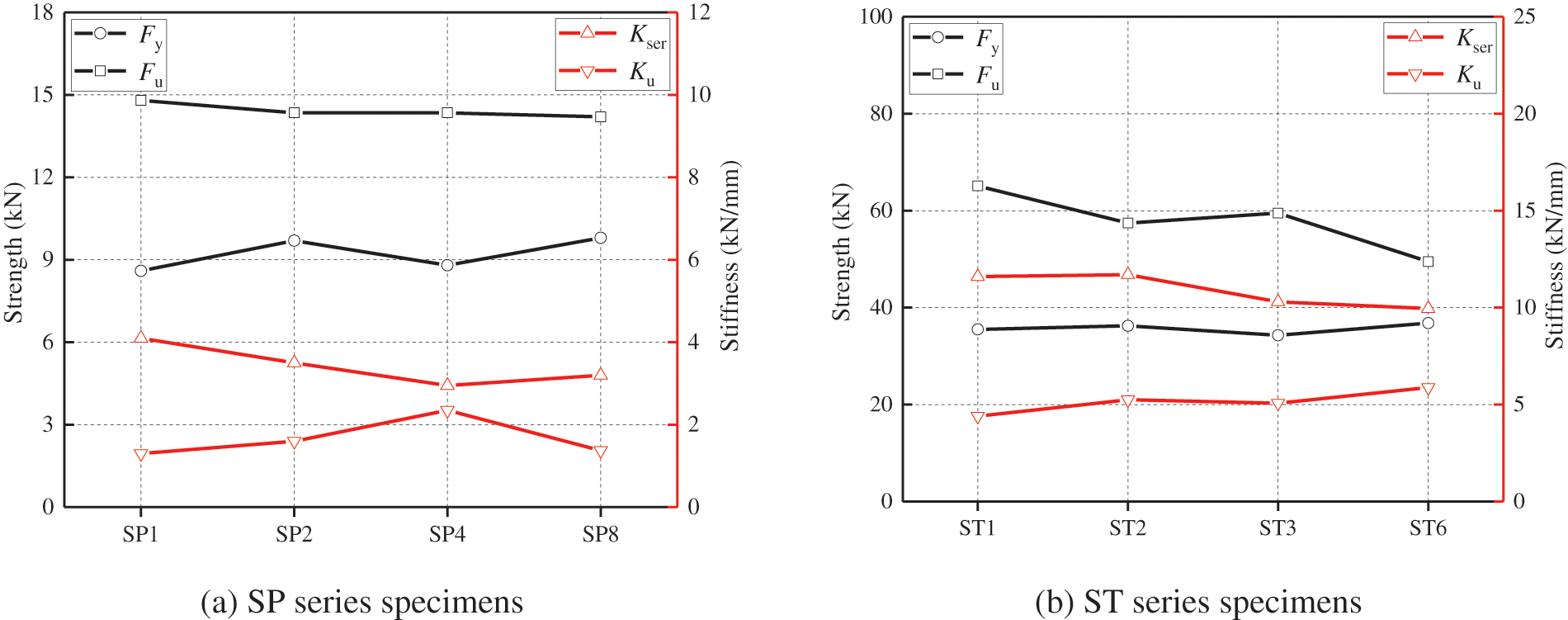
Figure 13: Average strength and stiffness per fastener
With the increase of fastener number, the ultimate strength and initial stiffness of individual fasteners did not show a regular tendency for both ST and SP series specimens. Most fluctuations in Fig. 13 were caused by the material, processing, and assembly differences. However, for the ST6 specimens, due to the decline of the ductility behavior and the appearance of severe timber row shear failure, the ultimate strength Fu of a single steel-tube declined. With the changing of ductility factors and failure modes, the effective number of fasteners declines, which is reflected in Eq. (14) by comparing ad with 13d. Therefore, the effective number of fasteners is equal to their actual quantity for the joint evaluated as ductile failure. For the joint occurring brittle failures, the calculation of the effective number of fasteners is unnecessary, and the prediction of ultimate strength should turn to the calculation for the resistances of possible brittle failures. In addition, the tensile stiffness per fastener at both serviceability limit and ultimate limit states were not affected by group-dowels effect. The slip stiffness of the STS joint with dowel-type fasteners can be solved by the beam theory of elastic foundation, which was affected by the timber foundation coefficient and bending performances of the dowel [5].
This article presents the experimental results of STS joints with small diameter screws and large diameter steel-tubes. The experimental results were analyzed in terms of the tension strength, slip stiffness, and failure modes. The failure mechanisms and ductility behaviors were discussed combined with the tensile resistances of potential failure modes. Valuable conclusions are summarized as follows:
i) The tensile strengths of the STS with one pair of screws and one steel-tube were 14.8 and 65.1 kN, respectively. All groups of STS specimens displayed the yielding or shear failure of the screw and steel-tube, as well as the embedding failure of timber. The failure modes and ductility factors of the STS joint with large diameter steel-tubes were similar to those with small diameter screws, thanks to the application of hollow structure in steel-tube.
ii) The ductility factors of SP series specimens ranged from 3.59 to 5.87, while those of ST series specimens ranged from 2.79 to 3.88. The ductility factors declined with the increase in the quantity of fasteners. With the increase in the quantity of fasteners, the typical failure modes turned to brittle failure modes, including timber splitting failure and row shear failure, from pure ductile failure.
iii) The theoretical values for the tensile strengths of various failure modes were calculated. The accuracy is verified by comparing it with the experimental values of tensile strengths of STS joints. By comparing the tensile strengths of potential failure modes, the ductility behavior of the STS joint can be predicted and divided into ductile failure modes and brittle failure modes.
iv) The slip stiffness per fastener was essentially the same for the STS joint with multi-fasteners. For the joint feathered with ductile and splitting failures, the effective number of fasteners can be determined as the actual number of fasteners. However, the effective number of fasteners for the joint with brittle failures was uncertain, and the tensile strength should be predicted based on the brittle failure modes.
Further investigations will focus on the performance improvement of STS joints with various diameter fasteners by self-tapping screw reinforcement, for the STS joints showing timber splitting failure and row shear failure. The tensile strength, failure mechanisms, and ductility classification will be investigated based on the tensile tests by considering the effects of self-tapping screw number and arrangement, as well as the diameter of the fastener. In addition, the STS joints using steel-tubes show the significant advantage in improving the ductility of the joints with large diameter fasteners. Therefore, the optimal design of the ratio between the wall thickness and diameter for the joint using steel-tubes will be investigated further.
Funding Statement: This experimental programme was supported by National Natural Science Foundation of China (Grant Nos. 52208253 and 51878344), Postdoctoral Foundation of Jiangsu Province (Grant No. 2021K128B), and Jiangsu Funding Program for Excellent Postdoctoral Talent, which are highly appreciated.
Conflicts of Interest: The authors declare that they have no conflicts of interest to report regarding the present study.
References
1. Johansen, K. W. (1949). Theory of timber connections. International Association for Bridge & Structural Engineering, 9, 249–262. [Google Scholar]
2. EN 1995−1−1:2004 (2004). Eurocode 5: Design of timber structures–Part 1–1: General-common rules and rules for buildings. Brussels, Belgium: European Committee for Standardization. [Google Scholar]
3. Xu, B. H., Liu, X., Zhao, Y. H., Bouchaïr, A. (2022). Load-carrying capacity of dowelled joints with slotted-in steel plate loaded at an angle to the grain. Structures, 35, 350–359. https://doi.org/10.1016/j.istruc.2021.11.019 [Google Scholar] [CrossRef]
4. Ringhofer, A., Brandner, R., Blaß, H. J. (2018). Cross laminated timber (CLTDesign approaches for dowel-type fasteners and connections. Engineering Structures, 171, 849–861. https://doi.org/10.1016/j.engstruct.2018.05.032 [Google Scholar] [CrossRef]
5. Tao, H., Yang, H., Ju, G., Shi, B. (2021). Elastic stiffness of timber joints with dowel-type fasteners and slotted-in steel plate based on the theory of beam on elastic foundation. Construction and Building Materials, 294, 123569. https://doi.org/10.1016/j.conbuildmat.2021.123569 [Google Scholar] [CrossRef]
6. Schweigler, M., Bader, T. K., Hochreiner, G., (2018). Engineering modeling of semi-rigid joints with dowel-type fasteners for nonlinear analysis of timber structures. Engineering Structures, 171, 123–139. https://doi.org/10.1016/j.engstruct.2018.05.063 [Google Scholar] [CrossRef]
7. Johanides, M., Lokaj, A., Dobes, P., Mikolasek, D. (2022). Numerical and experimental analysis of the rotational stiffness of a timber semi-rigid dowel-type connection. Materials, 15, 5622. https://doi.org/10.3390/ma15165622 [Google Scholar] [PubMed] [CrossRef]
8. Johanides, M., Lokaj, A., Dobes, P., Mikolasek, D. (2022). Numerical and experimental analysis of the load-carrying capacity of a timber semi-rigid dowel-type connection. Materials, 15, 7222. https://doi.org/10.3390/ma15207222 [Google Scholar] [PubMed] [CrossRef]
9. Xu, B. H., Jing, C. K., Bouchaïr, A. (2021). Experimental analysis of the influence of the fastener type on the embedment strength parallel to the grain in glued laminated timber. Journal of Materials in Civil Engineering, 33(2), 06020023. https://doi.org/10.1061/(ASCE)MT.1943-5533.0003599 [Google Scholar] [CrossRef]
10. Xu, B. H., Lin, J. B., Zhao, Y. H., Bouchaïr, A. (2022). Embedment behaviour of fully threaded bolts in glued laminated timber. European Journal of Wood and Wood Products, 81, 369–386. https://doi.org/10.1007/s00107-022-01901-8 [Google Scholar] [CrossRef]
11. Wang, X. T., Zhu, E. C., Niu, S., Wang, H. J. (2021). Analysis and test of stiffness of bolted joints in timber structures. Construction and Building Materials, 303, 124495. https://doi.org/10.1016/j.conbuildmat.2021.124495 [Google Scholar] [CrossRef]
12. Brandner, R., Ringhofer, A., Reichinger, T. (2019). Performance of axially-loaded self-tapping screws in hardwood: Properties and design. Engineering Structures, 188, 677–699. https://doi.org/10.1016/j.engstruct.2019.03.018 [Google Scholar] [CrossRef]
13. Fonseca, E. M. M., Leite, P. A. S., Silva, L. D. S., Silva, V. S. B., Lopes, H. M. (2022). Parametric study of three types of timber connections with metal fasteners using Eurocode 5. Applied Sciences, 12, 1701. https://doi.org/10.3390/app12031701 [Google Scholar] [CrossRef]
14. Cabrero, J. M., Yurrita, M. (2018). Performance assessment of existing models to predict brittle failure modes of steel-to-timber connections loaded parallel-to-grain with dowel-type fasteners. Engineering Structures, 171, 895–910. https://doi.org/10.1016/j.engstruct.2018.03.037 [Google Scholar] [CrossRef]
15. Quenneville, J. H. P., Mohammad, M. (2001). Design method for bolted connections loaded perpendicular-to-grain. Canadian Journal of Civil Engineering, 28(6), 949–959. https://doi.org/10.1139/l01-059 [Google Scholar] [CrossRef]
16. Quenneville, J. H. P., Mohammad, M. (2001). On the failure modes and strength of steel-wood-steel bolted timber connections loaded parallel-to-grain. Canadian Journal of Civil Engineering, 27(4), 761–773. https://doi.org/10.1139/l00-020 [Google Scholar] [CrossRef]
17. Stahl, D. C., Wolfe, R. W., Begel, M. (2004). Improved analysis of timber rivet connections. Journal of Structural Engineering, 130(8), 1272–1279. https://doi.org/10.1061/(ASCE)0733-9445(2004)130:8(1272) [Google Scholar] [CrossRef]
18. Zarnani, P., Quenneville, P. (2014). Strength of timber connections under potential failure modes: An improved design procedure. Construction and Building Materials, 60, 81–90. https://doi.org/10.1016/j.conbuildmat.2014.02.049 [Google Scholar] [CrossRef]
19. Jensen, J. L., Quenneville, P. (2010). Fracture mechanics analysis of row shear failure in dowelled timber connections. Wood Science and Technology, 44(4), 639–653. https://doi.org/10.1007/s00226-009-0295-9 [Google Scholar] [CrossRef]
20. Jensen, J. L., Quenneville, P. (2011). Experimental investigations on row shear and splitting in bolted connections. Construction and Building Materials, 25(5), 2420–2425. https://doi.org/10.1016/j.conbuildmat.2010.11.050 [Google Scholar] [CrossRef]
21. Schmid, M., Blaβ, H. J., Frasson, R. P. M. (2002). Effect of distances, spacing and number of dowels in a row on the load carrying capacity of connections with dowels failing by splitting. Proceedings of the 35th CIB-W18 Meeting, CIB-W18/35-7-5. Kyoto, Japan. [Google Scholar]
22. Wrzesniak, D., Fragiacomo, M., Jorissen, A. (2014). Alternative approach to avoid brittle failure in dowelled connections. Materials and Joints in Timber Structures, 9, 273–289. https://doi.org/10.1007/978-94-007-7811-5 [Google Scholar] [CrossRef]
23. Jockwer, R., Fink, G., Köhler, J. (2018). Assessment of the failure behaviour and reliability of timber connections with multiple dowel-type fasteners. Engineering Structures, 172, 76–84. https://doi.org/10.1016/j.engstruct.2018.05.081 [Google Scholar] [CrossRef]
24. Quenneville, P. (2017). Brittle failures of connections loaded parallel-to-grain. Proceedings of the Conference of COST Action FP1402, pp. 154–166. Graz, Austria. [Google Scholar]
25. Yurrita, M., Cabrero, J. M. (2021). Experimental analysis of plug shear failure in timber connections with small diameter fasteners loaded parallel-to-grain. Engineering Structures, 238, 111766. https://doi.org/10.1016/j.engstruct.2020.111766 [Google Scholar] [CrossRef]
26. Kangas, J., Vesa, J. (1998). Design on timber capacity in nailed steel-to-timber joints. Proceedings of CIB-W18 Timber Structures, pp. 31–74. Savonlinna, Finland. [Google Scholar]
27. Johnsson, H., Parida, G. (2013). Prediction model for the load-carrying capacity of nailed timber joints subjected to plug shear. Materials and Structures, 46(12), 1973–1985. https://doi.org/10.1617/s11527-013-0030-8 [Google Scholar] [CrossRef]
28. Li, Z., Wang, C., Wang, R., (2021). Application of screw reinforcement in the slotted-in bamboo-steel-bamboo connections. Structures, 33, 4112–4123. https://doi.org/10.1016/j.istruc.2021.07.024 [Google Scholar] [CrossRef]
29. Zhang, C., Guo, H., Jung, K., Harris, R., Shao, W. C. (2019). Using self-tapping screw to reinforce dowel-type connection in a timber portal frame. Engineering Structures, 178, 656–664. https://doi.org/10.1016/j.engstruct.2018.10.066 [Google Scholar] [CrossRef]
30. Song, L., Wu, J., Yang, H., Tang, Z., Zeng, T. et al. (2020). Experimental study on load-carrying behavior of bolted joints reinforced with nail plates for timber structures. Building Structure, 50(5), 33–37. [Google Scholar]
31. Pavković, K., Stepinac, M., Rajčić, V. (2020). Brittle failure modes in reinforced and non-reinforced timber joint with large diameter fastener loaded parallel to grain. Engineering Structures, 222, 111104. https://doi.org/10.1016/j.engstruct.2020.111104 [Google Scholar] [CrossRef]
32. EN 408:2003 (2003). Timber structures–structural timber and glued laminated timber–determination of some physical and mechanical properties. Brussels, Belgium: European Committee for Standardization. [Google Scholar]
33. EN 13183-1:2002 (2002). Moisture content of a piece of sawn timber–part 1: Determination by oven dry method. Brussels, Belgium: European Committee for Standardization. [Google Scholar]
34. DIN 517:2016−12 (2016). Hexagon head wood screws. Berlin, Germany: DIN Standards Committee Fastener. [Google Scholar]
35. ASTM F1575−17 (2017). Standard test method for determining bending yield moment of nails. West Conshohocken, Pennsylvania, USA: ASTM International. [Google Scholar]
36. EN 1382:2016 (2016). Timber structures–test methods–withdrawal capacity of timber fasteners. Brussels, Belgium: European Committee for Standardization. [Google Scholar]
37. ISO 6892:1998 (1998). Metallic materials–tensile testing at ambient temperature. Geneva, Switzerland: International Organization for Standardization. [Google Scholar]
38. ASTM D5764−97a (2013). Standard test method for evaluating dowel-bearing strength of wood and wood-based products. West Conshohocken, Pennsylvania, USA: ASTM International. [Google Scholar]
39. EN 12512:2001 (2001). Timber structures–test methods–cyclic testing of joints made with mechanical fasteners. Brussels, Belgium: European Committee for Standardization. [Google Scholar]
40. EN 26891−1991 (1991). Timber structures–joints made with mechanical fasteners–general principles for the determination of strength and deformation characteristics. Brussels, Belgium: European Committee for Standardization. [Google Scholar]
41. Shi, B., Yang, H., Liu, J., Crocetti, R., Liu, W. (2020). Short- and long-term performance of bonding steel-plate joints for timber structures. Construction and Building Materials, 240, 117945. https://doi.org/10.1016/j.conbuildmat.2019.117945 [Google Scholar] [CrossRef]
42. Brühl, F., Kuhlmann, U. (2017). Consideration of connection ductility within the design of timber structures. Proceedings of the Conference of COST Action FP1402, pp. 32–45. Graz, Austria. [Google Scholar]
43. Yurrita, M., Cabrero, J. M. (2021). On the need of distinguishing ductile and brittle failure modes in timber connections with dowel-type fasteners. Engineering Structures, 242, 112496. https://doi.org/10.1016/j.engstruct.2021.112496 [Google Scholar] [CrossRef]
44. Jorissen, A. (1998). Double shear timber connections with dowel type fasteners (Ph.D. Thesis). Delft University of Technology, Netherlands. [Google Scholar]
45. Yurrita, M., Cabrero, J. M. (2020). New design model for splitting in timber connections with one row of fasteners loaded in the parallel-to-grain direction. Engineering Structures, 223, 111155. https://doi.org/10.1016/j.engstruct.2020.111155 [Google Scholar] [CrossRef]
46. Yurrita, M., Cabrero, J. M. (2020). Effective thickness of timber elements for the evaluation of brittle failure in timber-to-steel connections with large diameter fasteners loaded parallel-to-grain at the elastic range: A new method based on a beam on elastic foundation. Engineering Structures, 209, 109959. https://doi.org/10.1016/j.engstruct.2019.109959 [Google Scholar] [CrossRef]
47. Yurrita, M., Cabrero, J. M. (2020). New design model for brittle failure in the parallel-to-grain direction of timber connections with large diameter fasteners. Engineering Structures, 217, 110557. https://doi.org/10.1016/j.engstruct.2020.110557 [Google Scholar] [CrossRef]
48. Yurrita, M., Cabrero, J. M., Quenneville, P. (2019). Brittle failure in the parallel-to-grain direction of multiple shear softwood timber connections with slotted-in steel plates and dowel-type fasteners. Construction and Building Materials, 216, 296–313. https://doi.org/10.1016/j.conbuildmat.2019.04.100 [Google Scholar] [CrossRef]
Cite This Article
 Copyright © 2023 The Author(s). Published by Tech Science Press.
This work is licensed under a Creative Commons Attribution 4.0 International License , which permits unrestricted use, distribution, and reproduction in any medium, provided the original work is properly cited.
 Downloads
 Citation Tools