
 Submit a Paper
 Propose a Special lssue
 Open Access
ARTICLE

Molecular Dynamics Simulation of Interface Properties between Water-Based Inorganic Zinc Silicate Coating Modified by Organosilicone and Iron Substrate
1 Science and Technology on Vacuum Technology and Physics Laboratory, Lanzhou Institute of Physics, Lanzhou, 730000, China
2 Zhejiang Provincial Key Laboratory for Cutting Tools, Taizhou University, Taizhou, 318000, China
3 School of Energy Engineering, Yulin University, Yulin, 719000, China
* Corresponding Author: Yuqing Xiong. Email:
(This article belongs to the Special Issue: Computational Tools for Renewable Materials)
Journal of Renewable Materials 2023, 11(4), 1715-1729. https://doi.org/10.32604/jrm.2022.024023
Received 22 May 2022; Accepted 18 July 2022; Issue published 01 December 2022
 View Full Text
 Download PDF
Abstract
The interface properties of Fe(101)/zinc silicate modified by organo-siloxane (KH-570) was studied by using the method of molecular dynamics simulation. By calculating the temperature and energy fluctuation of equilibrium state, equilibrium concentration distribution, MSD of layer and different groups, and interaction energy of two interface models, the influencing mechanism on the interface properties of adding organosiloxane into coating system was studied at the atomic scale. It shows that the temperature and energy of interface oscillated in a small range and it was exited in a state of dynamic equilibrium within the initial simulation stage (t < 20 ps). It can be seen from the multiple peak states of concentration distribution that the iron substrate, organo-siloxane and zinc silicate are distributed in the form of a concentration gradient in the real environment. The rapid diffusion of free zinc powder in zinc silicate coating was the essential reason that affected the comprehensive properties of coating. The interface thickness decreased from 7.45 to 6.82 Å, the MSD of free zinc powder was effectively reduced, and the interfacial energy was increased from 104.667 to 347.158 kcal/mol after being modified by organo-siloxane.Graphic Abstract
Keywords
The corrosion of materials will bring very serious safety hidden danger that is a common factor of accidents. The annual economic loss caused by corrosion accounts for more than 3% of China’s GDP [1,2]. In the field of oil and gas exploitation and transportation, the phenomenon of corrosion and perforation will occur and cause pipeline rupture when the underground oil and gas transport pipeline is put into operation for one to two years, which will lead to leakage of oil and gas, environmental pollution, and even cause fire, explosion and other accidents, threatening personal safety and causing significant asset losses [3–6]. Because of the organic solvent of this material system, such as toluene, xylene, etc., it will cause relatively serious pollution to the environment in the construction or applied process, and impose a serious impact on the local ecological environment [7–9]. Therefore, it is of great significance to develop a material system with excellent corrosion resistance, and economic and environmental protection for the sustainable development of society and environment [10]. Compared with unctuous coating, water-based coating has the advantages of lower cost, less environmental pollution and excellent comprehensive performance for the anti-corrosion of oil and gas transportation pipelines [11–13]. The water-based inorganic zinc-rich coating usually refers to the silicate of alkali metals including Li, Na, K as film forming material, water as the solvent, and free metal zinc powder as the main anti-rust pigment composition [14–17]. The aqueous solution of alkali metal silicate is the main factor to determine the coating varieties and properties [18,19]. Compared to other coating types, waterborne inorganic zinc-rich coating has many excellent performances, such as the nearly zero emission of VOC, excellent weather resistance, strong adhesion, and special self-repairing [20–22]. It has great advantages in the fields of high temperature resistance, water resistance, acid and alkali resistance and heavy-duty and has been successfully used in a variety of industries [23].
However, there are widespread problems with water-based zinc-rich silicate coatings, such as poor coating flexibility, and easy to flash rust when the dispersion medium water and steel structure contact, which needs to be overcome in demand [24,25]. At present, researchers have carried out a lot of studies on selection of alkali metals of silicate, and properties modification of film forming material. The chemical formula of alkali metals silicate can be expressed as M2O•nSiO2(M = Li, Na and K), where n is the modulus of alkali metal silicate, that represents the ratio of moles number of silicon dioxide to alkali metal oxide and is a dimensionless parameter [26]. Study shows that different modules of alkali silicate have a great influence on the coatings performance [27,28]. The radius of lithium, sodium and potassium ions in alkaline silicate aqueous solution is 6.8 nm, 9.8 nm and 13.3 nm, respectively. The radius of lithium ion is far smaller than that of sodium ion and potassium ion. The Li+ has the highest charge density, and its corresponding radius of hydration ion is the largest, which can effectively prevent the agglomeration of SiO2 in an aqueous solution. Therefore, a stable solution of lithium silicate with modulus (SiO2/Li2O molar ratio) of up to 25 can be obtained. Compared with sodium and potassium waterborne inorganic zinc-rich coatings, the lithium silicate zinc-rich coatings have the advantages of good water resistance, temperature resistance and fast self-curing speed, but their large-scale application is limited by their high price [29]. For sodium and potassium silicate aqueous solution, the self-curing process can be realized when the modulus of sodium silicate and potassium silicate is greater than or equal to 4 and 5, respectively. However, when the modulus of sodium silicate aqueous solution is increased, the solution viscosity increases sharply and the stability decreases [30,31]. At present, self-curing sodium silicate waterborne inorganic zinc-rich coating cannot be realized as the modulus of prepared sodium silicate solution is smaller than 4. By changing the stability of potassium silicate aqueous solution, the self-curing water-based inorganic zinc rich coating with modulus greater than 5 and high performance can be obtained. The research on the properties modification of film forming material mainly focuses on the modification and improvement of the potassium silicate coating properties, which is used to solve the problems of poor flexibility and flash rust of coating [32,33]. The commonly used method is adding flexible polymer modifier into silicate aqueous solution at the synthesis stage to improve the crosslinking degree of silicate and the flexibility of the internal chain segments of coating.
The most commonly used modifiers are silicon organic matter, such as the organosiloxane (KH-570), silicon acrylic emulsion, etc. Relevant research shows that the problem of flexibility and rust flash of modified potassium silicate coating can be effectively solved [34,35]. Also, the water-based inorganic zinc-rich coating modified by organosilicon has significant improvement in curing rate, salt spray resistance, mechanical properties and so on [36]. Nevertheless, the involved modification mechanism is only summarized based on the macroscopic test results, and there is no relevant research report on the micro level. It is well known that the interface formed between the coating and substrate plays a decisive role in the coating performance. The interface with high stability and closer combination can effectively improve the adhesion between them and significantly delay the diffusion process of corrosion factors in the coating. At present, a complete system of theoretical research on the interface properties has not been formed, and there is also a lack of targeted study on the addition of third-phase substances to the interface properties of coating. Therefore, it has great significance to study the interface properties between modified aqueous inorganic potassium silicate coating and substrate.
Based on the above background, the molecular dynamics simulation of interface between the zinc silicate primer and iron substrate was carried out to determine the effect of adding modified silicone components into the zinc silicate coating on the interface properties in this paper. The main purpose is to qualitatively study the mechanism of modifying waterborne inorganic zinc-rich coating by using the KH-570, and to study the formation mechanism and related properties of the interface at atomic levels. The interface models of Fe(101)/unmodified zinc silicate coating and Fe(101)/silicone modified zinc silicate coating was established. By calculating the temperature and energy changes of model at equilibrium state, the concentration distribution of interface layer and groups, the MSD changes of different groups at the interface and the interfacial interaction energy of two interface structure models, the essential reason of KH-570 organosilicon effectively improving the interface performance of Fe(101)/modified zinc silicate coating was analyzed and discussed, which can provide research ideas and experimental guidance for the development of zinc silicate coating with high performance.
2 Calculation Model and Method
The waterborne inorganic zinc-rich coating is composed of two components: binder and zinc powder. The binder will react with the zinc powder and the protected steel base material curing and forming an anticorrosive coating with a spatial cross-linked network structure. The binder is mainly high modulus silicate solution, including lithium silicate, sodium silicate, potassium silicate. There are a lot of -Si-OH bonds in silicate solution and they react with zinc powder to form a network complex of zinc silicate [37,38]. At the same time, the silicate can also react with iron atoms of metal substrate surface to form zinc iron silicate with excellent adhesion. After the irreversible curing reaction, a layer of zinc iron silicate complex that plays an anticorrosive role and prevents the corrosive medium from eroding steel base is exited. The crosslinking mechanism of waterborne inorganic zinc-rich coating can be expressed by following reaction equation, where M usually refers to lithium, sodium and potassium.
The principle of waterborne inorganic zinc-rich coating modified by organosilicon resin is that the -Si-OH group contained in organosilicon molecule is bonded with the silicate of high modulus, and more -Si-OH groups are introduced, as shown in Fig. 1. The addition of silicone resin can cause the following two results. First, the silicate molecules are connected and the molecular chain length improved that providing more concentrated active point and increasing the curing crosslinking degree in the curing process. Second, more -Si-OH groups can bond with zinc powder which can significantly speed up the curing process of coating and shorten the drying time.

Figure 1: Schematic diagram of silicate coating modified by organosilicon resin
The process of establishing the interface model of the inorganic high modulus zinc silicate coating and steel can be divided into three steps. First, the modeling of the steel substrate. Second, the models of zinc silicate coating and coating modified by silicone resin. Third, establishment of unmodified and modified zinc silicate/steel interface model. The detailed process of each step is as follows.
2.1.1 Model of Steel Substrate
Due to the variety of elements contained in steel, the content of other elements is relatively small compared with iron and has little impact on the actual simulation results. Therefore, to simplify the modeling and calculation process, the steel substrate was replaced by pure iron in this paper. Firstly, the crystal cell structure of iron element was introduced and the Fe(101) surface was selected for cutting. Since the corresponding angles are 70°, the lattice mismatch will occur when the interface structure is superimposed, causing the assigned force field cannot be truly reflected in the calculation process and leading to inaccurate calculation results. Therefore, it is necessary to reconstruct the section model lattice and transform it into an orthogonal structure. The {(U V)}={(3 -1) (0 1)} was selected as Fe(101) reconstruction surface after debugging. Then, the crystal cell was expanded to ensure that the cell size was close to zinc silicate coating. After testing, the reconstructed cell was expanded to (5 × 15). In order to make the substrate model more consistent with the real situation, the atomic layer number was set as eleven layers. Finally, the eight bottom layers were fixed and the three top layers were relaxed to simulate the substrate material and the substrate surface, respectively. The established model of substrate was shown in Fig. 2.

Figure 2: Model of Fe substrate
2.1.2 Blending Model of Inorganic High Modulus Zinc Silicate Coating
The two-dimensional structure of the high modulus silicate (Me-nSiO2 for short) and silicone modified resin was established by using the Visualizer module model. In this paper, the γ-methylacrylloxy propyl trimethoxy silane (KH-570) was selected as the organic silicon molecule and the modulus n was set as 5. The reasonable three-dimensional structures were obtained after energy optimization of the two models and the reactive oxygen and silicon atoms of the Me-nSiO2 and KH-570 molecular chain structures were named R1 and R2, respectively. The three-dimensional molecular structures were shown in Fig. 3.

Figure 3: Three-dimensional molecular structures: (a) Me-nSiO2; (b) KH-570
The anticorrosion principle of waterborne inorganic zinc-rich coatings is mainly manifested in electrochemical protection effect and shielding protection effect. The electrochemical protection effect is the first stage of anticorrosive process for waterborne inorganic zinc-rich coating. The coating contains a lot of zinc powder particles which is a more active metal compared with the protected steel substrate. Under the condition of electrolyte solution, the galvanic cells are formed between zinc powder and iron substrate, in which zinc powder and base iron particles acted as the anode and cathode of galvanic cell, respectively [39]. Due to the lower electrode potential of zinc particles, the zinc particles are preferentially corroded as sacrificial anode to protect the cathode steel substrate. In terms of shielding protection effect, zinc powder and iron base atoms react with silicate to form zinc iron silicate complex in the process of coating curing. In addition, the insoluble zinc complexes in the galvanic cell reaction. These complexes will deposit on the surface of the protected substrate and form a dense protective layer in the pores inside the coating [40]. Therefore, the zinc powder in waterborne inorganic zinc-rich coating exists in two states—free zinc powder and bonded complex. According to industry standard HG/T 3668-2000, the non-volatile minute metal zinc content in inorganic zinc-rich primer is not less than 80 wt.%. Relevant experimental studies show that increasing the content of zinc powder in waterborne inorganic zinc-rich primer can obviously shorten the curing time and improved the protection effect of substrate in the salt spray resistance test [41–44]. In order to make the simulation model accord with the experimental situation, the zinc powder content was set as 90 wt.%.
By analyzing the structure of inorganic zinc silicate coating, it can be seen that Zinc particles in silicate coating were in the mixed form with part of them bound with hydroxyl and the other was coated in silicate complex. Therefore, the modeling procedure of zinc silicate was as follows: all hydrogen atoms in the hydroxyl of silicate were replaced by zinc atoms, and the rest formed a blend structure with cross-linked zinc silicate. For the KH-570 modified zinc silicate cross-linked structure, the method of block copolymer was introduced to build the model of Zinc silicate and KH-570 molecular chain with the addition ratio of 20 wt.%. The proportional interval of Me-nSiO2 and KH-570 molecular chain fragments was set as 4 and 1. The zinc atom connecting to the middle of oxygen atom in silicate straight chain was set as the head and tail atom, respectively, to realize the spatial cross-linked structure. The final model was written as Me-nSiO2/KH-570/Zn. Theoretically, all of the -Si-OH groups are involved in the bonding of zinc elements to form a spatial cross-linked zinc silicate coating. Based on cross-linking mechanism between zinc powder and silicate, the crosslinking degree of waterborne inorganic zinc-rich coating was set as 96% in view of the steric hindrance effect in the actual reaction, and the crosslinking reaction was simulated as follows. The range of cutoff distance between the zinc atom and the oxygen atom was set as 0.4–1.0 nm when the cross-linking reaction process of hybrid state model applied structural optimization and dynamic simulation is simulated. When the nearest reactive zinc-oxygen atomic pair is within the distance range, the corresponding zinc atom and oxygen atom reacted to form chemical bond between them. The curing degree of epoxy resin is improved by increasing the cutoff distance until the predetermined curing degree is reached, and the non-bonded reactive atoms are saturated with hydrogen atoms. The cross-linking reaction between silicate chains is simulated according to the self-programmed cross-linking reaction program. The structure of zinc silicate model obtained from cross-linking reaction under each cutoff distance is optimized to obtain the geometries with reasonable bond length and stable molecular configuration. A coating model of zinc silicate without being modified by silicone resin was also established for comparison, which was recorded as Me-nSiO2/Zn. The two established coating models were shown in Fig. 4.

Figure 4: Established coating models: (a) Me-nSiO2/Zn; (b) Me-nSiO2/Zn/KH-570
2.1.3 Model of Zinc Silicate/Iron Interface
The interface model of iron substrate and zinc silicate coating was performed by the build layers function in Materials Studio 2019 software. The iron model in Fig. 2 was used as the substrate for layer 1, and the zinc silicate coating and KH-570 modified zinc silicate coating model established in Fig. 4 were used as the layer 2. In order to eliminate the interaction with other adjacent cells of the periodic structure, the thickness of the vacuum layer was set as 30 Å. The size of the two interface models was 38.02 × 37.84 × 132.44 Å3 and 35.17 × 35.02 × 104.12 Å3, respectively. The established interface model was shown in Fig. 5.

Figure 5: Interface model: (a) Fe-Me-nSiO2/Zn; (b) Fe-Me-nSiO2/KH-570/Zn
2.2 Optimization Process and Parameter Setting
Before dynamic simulation, the structure of interface was optimized to minimize its energy and stabilize the structure. The dynamics simulation process was performed by using the Forcite Plus module of Materials Studio 2019 software. The simulation includes following three parts. Firstly, in order to fully relax the atoms in the material model and reduce the internal stress of coating, it is necessary to conduct an annealing simulation for each layered and interface model. The annealing temperature range and cycles were set as 300–500 K and 5. Secondly, the NVT molecular dynamics simulation with temperature of 298 K was carried out to enable the molecules and atoms in the system to obtain enough kinetic energy that can eliminate agglomeration between atoms in the simulation process. Thirdly, the NPT molecular dynamics simulation under 298 K and 1 atm were carried out to calculate and analyze the related performance of interface. The COMPASS force field was used in the simulation process and the simulation accuracy was set as fine. When the dynamic balance of NVT and NPT simulation process was carried out for zinc silicate and KH-570 models, the simulation time and step size were set as 200 ps and 1 ps, respectively. While for dynamic simulation of interface model, the corresponding simulation time and step size are set to 1000 ps and 1 ps, respectively. The temperature and pressure of the interface system were adjusted by the Andersen thermostat and Berendsen controller in the simulation process.
3.1 Equilibrium State Analysis of Interface
The equilibrium state is a stable state in which the values of a system deviate slightly from the equilibrium, also called fluctuation state. The equilibrium state of interface of zinc silicate coating system and substrate is usually studied from the energy and temperature perspectives. The curve of temperature variation in dynamic equilibrium process of interface was shown in Fig. 6. It can be seen from the figure that the temperature of system oscillated between the highest temperature of 313.8 K and the lowest temperature of 271.0 K in the equilibrium process. The temperature fluctuated around the initial setting of 298 K, and the fluctuation range was less than 10%. The temperature did not fluctuate significantly during the simulation process, and the dynamic equilibrium state was maintained all the time.

Figure 6: Curve of temperature variation in dynamic equilibrium process of interface
Generally speaking, the interface energy usually includes three parts: kinetic energy, potential energy, and non-bonding energy. The kinetic energy refers to the total energy of all atoms that belong to the interface structure system moving in random motion. The potential energy refers to the total energy of all atoms in the system interacting with each other in their different positions. The non-bonding energy was composed of three interaction energy types between atoms, namely the electrostatic interaction energy, Van der Waals interaction energy and hydrogen bond interaction energy, respectively. The curve of variation in dynamic equilibrium process of interface was shown in Fig. 7. It can be seen that the three types of energy fluctuate slightly bigger at the early stage, and the simulation time is within the range of 50 ps. Then, they fluctuate up and down in a small range with the steady simulation process, evolve into a straight line basically, and finally reach the dynamic equilibrium state.

Figure 7: Curve of energy variation in dynamic equilibrium process of interface
It can be seen from the temperature and energy variation curves of the zinc silicate coating interface during the dynamic equilibrium simulation process that the temperature and energy of the interface structure system fluctuate in a very small interval after the dynamic equilibrium simulation of NVT and NPT at 298 K and 1000 ps, and the interface structure has been fully relaxed in which the movement of various internal atoms reached a stable state, the internal stress also reached a dynamic balance and the whole system was completed in a dynamic equilibrium state. Therefore, the subsequent dynamic performance calculation of interface was carried out under this simulated condition.
3.2 Equilibrium Concentration Distribution Analysis of Interface
The concentration of zinc silicate modified by silicone resin on Fe(101) surface from near to far constituted the concentration distribution between zinc silicate coating and iron substrate interface. Due to the different adsorption effects of the substrate surface on the components of the coating system, the concentration of zinc silicate and silicone resin in the interface is uneven. The closer to the substrate Fe(101) surface is, the more zinc silicate molecules are adsorbed, indicating that the interaction between them is increasing gradually and resulting in a directional stacking effect of a specific chain segment at the interface. In addition, the free state of zinc element caused by adding zinc particles in the paint preparation stage increases the reactivity with iron substrate, which can further improve the group concentration and bonding strength at the interface. By simulating the concentration distribution of each layer of the interface, the adsorption of zinc silicate molecular chain on the iron substrate surface and the influence law of organosilicon modified molecules on interface thickness can be studied quantitatively, which has certain guiding significance for the controllable interface study.
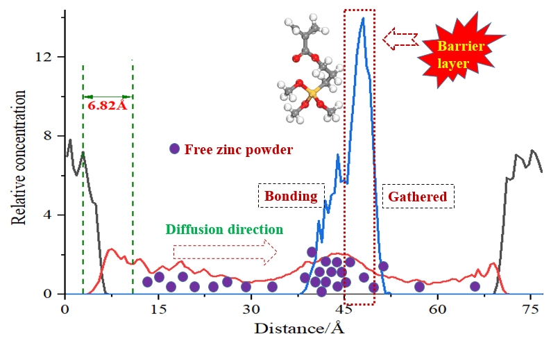
The interface structure is Fe(101) (layer 1), interface and zinc silicate layer (layer 2) from bottom to top. With the change of distance on the concentration distribution curve and the concentration of layer 1 and layer 2 is the peak corresponding to the interface layer. Therefore, the interface existed on the left side of concentration distribution curve. In the order from left to right, the distance between the valley of the last iron substrate concentration peak on the left and valley of the first zinc silicate coating concentration peak on the right is defined as the interface layer thickness. The concentration distribution curve of each layer at the Fe(101)/zinc silicate interface that takes the distance change along z direction as abscissa after equilibrium simulation was shown in Fig. 8. It can be seen from the figure the two concentration peaks of base iron atoms, zinc silicate coating at Fe(101)/zinc silicate coating interface appeared in the range of 0~8.30 Å, 72.08~79.76 Å and 4.63~74.60 Å, respectively, after dynamic simulation. For the interface of Fe(101)/silicone modified zinc silicate coating, the corresponding distance range between two concentration peaks of base iron atoms, silicone modified zinc silicate coating and organosilicon chain (KH-570) were 0~6.27 Å, 67.03~74.98 Å, 3.37~69.55 Å and 36.72~51.24 Å, respectively, after the kinetic simulation. The concentration peaks of layer 1, KH-570 and layer 2 all present multiple peak states, and they are distributed in the form of a concentration gradient in real environment. In the two types of interface, the left side trough of the second iron atom concentration peak and the right side trough of the first zinc silicate coating concentration peak were 2.75 Å, 1.86 Å and 10.20 Å, 8.68 Å, respectively. According to the interface thickness definition, the interface thickness of Fe(101)/unmodified zinc silicate coating and Fe(101)/silicone modified zinc silicate coating models was 7.45 Å and 6.82 Å, respectively. The concentration peak of zinc silicate coating shifted and approached the iron substrate, and the binding between zinc silicate coating and iron substrate became more solid with the addition of silicone modified molecules, resulting in the thickness decrease of the interface layer. The modified organosilicon molecular chain was clustered in the middle of the concentration peak interval of zinc silicate coating, and the peak width (14.52 Å) was a quarter of the zinc silicate coating concentration peak width (65.18 Å), which was roughly consistent with that the organosilicon molecular chain number accounts for 20% design in the modeling process. The siloxane group at the end of modified silicone molecular chain can react with two zinc silicate molecular chains at the same time, acting as an intermediate link between zinc silicate molecules, so it located in the middle position of zinc silicate concentration peak on the curve. Besides, the presence of modified silicone chains enhanced the active reaction sites inside the zinc silicate coating, effectively improving the internal coating density that not only restricted the movement of zinc silicate molecular chain segments and free zinc powder, but also hindered the diffusion of base iron atoms in the coating. Therefore, the curve shows that the interval of zinc silicate coating concentration peak was narrowed and the iron atom peak at the top was shifted to the left obviously.

Figure 8: Concentration distribution comparison of interface
3.3 Group Movement Ability Analysis of Interface
The interface performance directly determines the service life of zinc silicate coating in the application. The smaller relative motion degree between coating and substrate, the greater degree of mutual restriction and more solid interface bonding between them performed. The movement of groups at interface can be described by the mean square displacement (MSD), which represents the statistical situation of distance changing between a specific particle position at different times and the initial position. The MSD can be calculated by the following formula:
where N and t represent particles number of the specific groups and simulation time, respectively. The movement of all groups at the interface of Fe(101) substrate and modified zinc silicate was investigated by analyzing the changes of atomic layer 1 of iron substrate, layer 2 of silicone modified zinc silicate coating and all the groups at the interface. Among them, the zinc atom, silicon atom and oxygen atom at the sealing end of zinc silicate chain were denoted as SiO2-Zn, Si1 and O1, and the silicon atom and oxygen atom associated with the main chain were denoted as Si2 and O2. The modified organosilicon chain, the end capped siloxane group in organosilicon and the zinc powder added in the mixing stage were denoted as Free Zn, KH-570 and Si-O-CH3, respectively. In addition, the MSD of layer 1, layer 2 and other groups of the interface of unmodified zinc silicate coating and iron substrate were also calculated for comparison. In the later period of simulation, trailing often appears in the MSD curve because of the statistical error of computer that leads to the curve shift between mean square displacement and time. Therefore, the latter part of curve was omitted when we calculate the slope of mean square displacement varies with time. In this case, we take the changed interval of the time as t ∈ [0,900]. The calculation results were shown in Figs. 9a and 9b.

Figure 9: MSD curves of Fe(101)/zinc silicate interfacial layer and groups: (a) Layer 1 and low-speed groups; (b) Layer 2 and high-speed groups
It can be seen from Fig. 9a that the overall motion amplitude of layer 1 in the interface was very small (<5 Å2) and the MSD of layer 1 in the interface modified by silicone molecular chain was larger than that of the unmodified interface, while the MSD of zinc silicate coating increased linearly with the advance of simulation time. The MSD of layer 2 modified by organosilicon molecular chain was significantly smaller than that of the unmodified interface, and the decreased amplitude gradually increase with the simulation time. The addition of KH-570 organosilicon in zinc silicate coating system was beneficial to reduce the overall MSD of layer 2, make the coating binding more closely with the iron substrate, and prevent the coating from falling off the substrate in use, which was consistent with the conclusion in Section 3.2. The MSD of layer 2 was a result of joint interaction between the faster moving chain end group, the KH-570 chain end group, the free zinc powder and the slower moving zinc silicate molecular backbone. In the coating system, the overall movement of the molecular backbone is limited by the large volume, so the MSD can be ignored. In the molecular chain of zinc silicate, The O1, Si1 and SiO2-Zn atoms are located in the terminal groups of molecular backbone, while O2 and Si2 atoms are connected and located in the molecular backbone of zinc silicate. The MSD of the terminal group atoms was higher than that of the similar atoms in the main chain, which can be verified in Fig. 8a. The figure shows that O2 and Si2 atoms in the two types of interface connected and located in the molecular backbone, the MSD of them was basically equal and they are significantly smaller than that of O1 and Si1. The MSD of layer 2 and its internal groups in the silicone modified zinc silicate coating interface was larger than that of the unmodified zinc silicate coating interface. The main reason was that the presence of silicone molecular chain in zinc silicate coating increased the reactive sites of atoms in the terminal active groups. These active sites accelerated the movement of the terminal atoms in the zinc silicate molecular chain and increased the coating density. Finally, the overall MSD of layer 2 was significantly lower than that of the unmodified interface model. From Fig. 9b, it can be seen that the MSD of zinc powder was the largest, which up to 350 Å2 for the unmodified zinc silicate coating. However, after the modification of organic silicon, the MSD of zinc powder was greatly reduced, even lower than that of the whole layer 2. Therefore, it can be concluded that the significant decrease of MSD of free zinc powder in zinc silicate coating was the main reason for the drastic reduction of layer 2 MSD in KH-570 modified silicone coating system. The MSD value of free zinc powder was basically the same as that of siloxane group (Si-O-CH3) at the end of KH-570 chain, and the changing trend was also consistent. Further analysis has shown that the free zinc powder was combined with siloxane in KH-570, which effectively prevented the rapid diffusion of zinc powder in the zinc silicate coating, decreased the diffusion free path of zinc powder, and thus reduced the interface layer size.
3.4 Interaction Energy Analysis of Interface
In the interface of Fe(101)/silicone modified zinc silicate coating, there are many forms of interaction, including the interaction between the base iron atoms, the groups inside the zinc silicate coating, the interatomic interaction inside the KH-570 organic silicon molecule, the interaction between organic silicon molecule and zinc silicate molecule, the interaction between zinc silicate and organic silicon molecule and the substrate, etc. Among them, the interaction between zinc silicate molecules and iron substrate was the most important that will affect the stability of zinc silicate coating interface. Therefore, the interaction form between zinc silicate molecules and iron substrate is very important for the performance of the materials. The interface binding energy between zinc silicate and iron substrate in coating system was calculated and characterized by the following formula:
where the Einterface, Etotal,

According to formula (6), the interfacial energy of Fe(101)/zinc silicate and Fe(101)/silicone modified zinc silicate was −104.667 kcal/mol and −347.158 kcal/mol, respectively, and the interfacial energy of Fe(101)/zinc silicate coating modified by KH-570 silicone molecular chain increased significantly. The silicone molecular chain effectively improves the crosslinking degree of zinc silicate coating, reduce the interface thickness and increase the bonding force between the substrate and coating, which was in good consistent with the simulation results in the previous two sections.
A molecular dynamics simulation of the interfacial properties of Fe(101)/zinc silicate coating modified by KH-570 silicone molecular chain was carried out in this work. By calculating and analyzing the equilibrium state, equilibrium concentration distribution, mean square displacement and interaction energy, the results are as follows:
(1)The modified organosilicon molecular chain made the zinc silicate concentration peak shift and approach the iron substrate and the binding between zinc silicate coating and iron substrate became more solid. The interface thickness was decreased from 7.45 to 6.82 Å.
(2)The MSD of layer 2 in the two interfaces of Fe(101)/zinc silicate coatings was significantly greater than that of the iron substrate. The whole MSD of zinc silicate coating was significantly reduced after being modified by organosilicone. The main reason was that silicone molecules increased the density of zinc silicate coating and effectively blocked the diffusion free path of free zinc powder.
(3)The interfacial energy of Fe(101)/zinc silicate coating modified by KH-570 silicone molecular chain increased significantly. The interfacial energy of Fe(101)/zinc silicate and Fe(101)/silicone modified zinc silicate was −104.667 kcal/mol and −347.158 kcal/mol, respectively.
Funding Statement: This study was supported by the National Science Fundation of China (No. U1937601), and the National Natural Science Foundation of China (Grant No. NSFC51905471).
Conflicts of Interest: The authors declare that they have no conflicts of interest to report regarding the present study.
References
1. Ma, X. M., Zheng, M., Xu, W. C., Lu, D. Z., Ma, F. B. et al. (2021). Study of corrosion cost and control strategy. Marine Sciences, 45(2), 161–168. DOI 10.11759/hykx20200428001. [Google Scholar] [CrossRef]
2. Hou, B., Zhang, D., Wang, P. (2016). Marine corrosion and protection: Current status and prospect. Bulletin of Chinese Academy of Sciences, 31(12), 1326–1331. DOI 10.16418/j.issn.1000-3045.2016.12.006. [Google Scholar] [CrossRef]
3. Wang, P., Xiong, L., He, Z., Xu, X., Hu, J. et al. (2022). Effect of imidazoline derivatives on the corrosion inhibition of Q235 steel in HCl medium: Experimental and theoretical investigation. Corrosion Reviews, 40(3), 275–288. DOI 10.1515/corrrev-2021-0094. [Google Scholar] [CrossRef]
4. Xu, L., Liu, F., Liu, M., Wang, Z., Qian, Z. et al. (2019). Fabrication of repairable superhydrophobic surface and improved anticorrosion performance based on zinc-rich coating. Progress in Organic Coatings, 137, 105335. DOI 10.1016/j.porgcoat.2019.105335. [Google Scholar] [CrossRef]
5. Yang, X., Zhu, W. (2017). The performance of a waterborne zinc-rich coating from sodium silicate solution catalyzed by ammonium acetate. Protection of Metals and Physical Chemistry of Surfaces, 53(2), 299–305. DOI 10.1134/S2070205117020277. [Google Scholar] [CrossRef]
6. Sharma, K., Goyat, M. S., Vishwakarma, P. (2020). Synthesis of polymer nano-composite coatings as corrosion inhibitors: A quick review. Materials Science and Engineering, 983(1), 012016. DOI 10.1088/1757-899X/983/1/012016. [Google Scholar] [CrossRef]
7. Thandar, W., Win, Y. Y. K., Khaing, T., Suzuki, Y., Sugiura, K. et al. (2022). Investigation of initial atmospheric corrosion of carbon and weathering steels exposed to urban atmospheres in Myanmar. International Journal of Corrosion, 2022, 4301767. DOI 10.1155/2022/4301767. [Google Scholar] [CrossRef]
8. Du, X., Dai, X., Li, Z., Du, X., Shi, H. et al. (2021). Corrosion analysis and anti-corrosion measures of oil casing of sulfur content gas wells: A case study of Daniudi gas field in the Ordos Basin. Energy Reports, 7(2), 1280–1292. DOI 10.1016/j.egyr.2021.02.041. [Google Scholar] [CrossRef]
9. Burtuujin, G., Son, D., Jang, I., Yi, C., Lee, H. (2020). Corrosion behavior of pre-rusted rebars in cement mortar exposed to harsh environments. Applied Sciences, 10(23), 8705. DOI 10.3390/app10238705. [Google Scholar] [CrossRef]
10. Dinh, N. P., Sachiko, H., Minho, O., Equo, K. (2021). Influence of substrate microstructure on hydroxyapatite coating and corrosion behavior of coated Mg-Zn alloys. Surface & Coatings Technology, 421, 127414. DOI 10.1016/j.surfcoat.2021.127414. [Google Scholar] [CrossRef]
11. Li, W., Meng, L., Tang, J., Liu, R. (2020). Corrosion behavior and evaluation of modified silicate composite grounding material in soil. Earth and Environmental Science, 525(1), 012126. DOI 10.1088/1755-1315/525/1/012126. [Google Scholar] [CrossRef]
12. Katona, R., Lócskai, R., Bátor, G., Krójer, A., Kovács, T. (2019). Analysis of crude oil in terms of fouling and corrosion. Hungarian Journal of Industry and Chemistry, 47(2), 11–15. DOI 10.33927/hjic-2019-15. [Google Scholar] [CrossRef]
13. Fayomi, O. S. I. (2018). Data on the optimized sulphate electrolyte zinc rich coating produced through in-situ variation of process parameters. Date in Brief, 16, 141–146. DOI 10.1016/j.dib.2017.10.010. [Google Scholar] [CrossRef]
14. Liu, Y., Shi, J. (2022). Corrosion resistance of carbon steel in alkaline concrete pore solutions containing phytate and chloride ions. Corrosion Science, 205, 110451. DOI 10.1016/j.corsci.2022.110451. [Google Scholar] [CrossRef]
15. Nagasawa, M., Okada, N., Otsuka, N., Ohtsuka, T. (2018). Corrosion process of inorganic zinc-rich painted steel exposed to a high-chloride atmospheric environment. ISIJ International, 58(2), 316–322. DOI 10.2355/isijinternational.ISIJINT-2017-548. [Google Scholar] [CrossRef]
16. Park, J. H., Yun, T. H., Kim, K. Y., Song, Y. K., Park, J. M. (2012). The improvement of anticorrosion properties of zinc-rich organic coating by incorporating surface-modified zinc particle. Progress in Organic Coatings, 74(1), 25–35. DOI 10.1016/j.porgcoat.2011.09.012. [Google Scholar] [CrossRef]
17. Cheng, L., Luo, Y., Ma, S., Guo, W., Wang, X. (2019). Corrosion resistance of inorganic zinc-rich coating reinforced by Ni-coated coal fly ash. Journal of Alloys and Compounds, 786, 791–797. DOI 10.1016/j.jallcom.2019.01.368. [Google Scholar] [CrossRef]
18. Cui, S., Huang, J., Luo, J., Liang, W., Saucedo-Mora, L. et al. (2021). Evaluation of a sealed layer on a porous thermal barrier coating against molten calcium—magnesium—alumina—silicate corrosion. Materials & Design, 208, 109918. DOI 10.1016/j.matdes.2021.109918. [Google Scholar] [CrossRef]
19. Arman, S. Y., Bamezanzadeh, B., Farghadani, S., Mehdipour, M., Rajabi, A. (2013). Application of the electrochemical noise to investigate the corrosion resistance of an epoxy zinc-rich coating loaded with lamellar aluminum and micaceous iron oxide particles. Corrosion Science, 77(1), 118–127. DOI 10.1016/j.corsci.2013.07.034. [Google Scholar] [CrossRef]
20. Teng, S., Gao, Y., Gao, F., Kong, D., Zheng, X. et al. (2018). Zinc-reduced graphene oxide for enhanced corrosion protection of zinc-rich epoxy coatings. Progress in Organic Coatings, 123, 185–189. DOI 10.1016/j.porgcoat.2018.07.012. [Google Scholar] [CrossRef]
21. Schaefer, K., Miszczyk, A. (2013). Improvement of electrochemical action of zinc-rich paints by addition of nanoparticulate zinc. Corrosion Science, 66(910), 380–391. DOI 10.1016/j.corsci.2012.10.004. [Google Scholar] [CrossRef]
22. Park, S., Shon, M. Y. (2015). Effects of multi-walled carbon nano tubes on corrosion protection of zinc rich epoxy resin coating. Journal of Industrial and Engineering Chemistry, 21, 1258–1264. DOI 10.1016/j.jiec.2014.05.042. [Google Scholar] [CrossRef]
23. Vigdorovich, V. I., Tsygankova, L. E., Shel, N. V., Golovchenko, A. O., Ostrikov, V. V. et al. (2019). Using data of weight tests and impedance spectroscopy to evaluate the protective effectiveness of zinc-rich oil coatings in corrosion of carbon steel. International Journal of Corrosion and Scale Inhibition, 8(2), 212–224. DOI 10.17675/2305-6894-2019-8-2-4. [Google Scholar] [CrossRef]
24. Chiter, F., Costa, D., Maurice, V., Marcus, P. (2020). Adsorption of 2-mercaptobenzimidazole corrosion inhibitor on copper: DFT study on model oxidized interfaces. Journal of the Electrochemical Society, 167(16), 161506. DOI 10.1149/1945-7111/abcd4f. [Google Scholar] [CrossRef]
25. Ikenna, B. O., Safwat, A. A., Dheeraj, S. C., Murntaz, A. Q. (2021). Electrochemical and computational insights on the application of expired metformin drug as a novel inhibitor for the sweet corrosion of C1018 steel. ACS Omega, 6(1), 65–76. DOI 10.1021/acsomega.0c03364. [Google Scholar] [CrossRef]
26. Ebadi, M., Majidian, H., Salahi, E., Faeghinia, A. (2020). Effect of the colloidal zirconia on corrosion resistance of low-cemented alumina mixes against steel slag. Journal of Asian Ceramic Societies, 9(1), 30–39. DOI 10.1080/21870764.2020.1847423. [Google Scholar] [CrossRef]
27. Kakaei, M. N., Danaee, I. (2013). Evaluation of cathodic protection behavior of waterborne inorganic zinc-rich silicates containing various contents of MIO pigments. Anti-Corrosion Method and Materials, 60(1), 37–44. DOI 10.1108/00035591311287438. [Google Scholar] [CrossRef]
28. Arman, S. Y., Ramezanzadeh, B., Farghadani, S., Mehdipour, M., Rajabi, A. (2013). Application of the electrochemical noise to investigate the corrosion resistance of an epoxy zinc-rich coating loaded with lamellar aluminum and micaceous iron oxide particles. Corrosion Science, 77(1), 118–127. DOI 10.1016/j.corsci.2013.07.034. [Google Scholar] [CrossRef]
29. Yeh, C. P., Tsai, K. C., Huang, J. Y. (2020). Influence of chloride concentration on stress corrosion cracking and crevice corrosion of austenitic stainless steel in saline environments. Materials, 13(24), 5640. DOI 10.3390/ma13245640. [Google Scholar] [CrossRef]
30. Ramezanzadeh, B., Arman, S. Y., Mehdipour, M. (2014). Anticorrosion properties of an epoxy zinc-rich composite coating reinforced with zinc, aluminum, and iron oxide pigments. Journal of Coatings Technology and Research, 11(5), 727–737. DOI 10.1007/s11998-014-9580-0. [Google Scholar] [CrossRef]
31. Krzysztof, K., Spychaj, T. (2014). Zinc-free varnishes and zinc-rich paints modified with ionic liquids. Corrosion Science, 78, 111–120. DOI 10.1016/j.corsci.2013.09.006. [Google Scholar] [CrossRef]
32. Deng, L., Miyatani, K., Suehuara, M., Amma, S. I., Ono, M. et al. (2021). Ion-exchange mechanisms and interfacial reaction kinetics during aqueous corrosion of sodium silicate glasses. npj Materials Degradation, 5(1), 15. DOI 10.1038/s41529-021-00159-4. [Google Scholar] [CrossRef]
33. Shetranjiwalla, S., Vreugdenhil, A. J., Strong, O. (2021). Interplay of hydrophobic thiol and polar epoxy silicate groups on microstructural development in low-alcohol, crosslinked sol-gel coatings for corrosion prevention. Coatings, 11(3), 306. DOI 10.3390/coatings11030306. [Google Scholar] [CrossRef]
34. Bao, Y., Yan, Y., Zhang, J., Ma, J., Zhang, W. et al. (2020). Effect of the feeding mode of cross-linker and microcapsule on the corrosion resistance and hydrophobicity of composite coatings. Arabian Journal of Chemistry, 13(12), 9068–9080. DOI 10.1016/j.arabjc.2020.10.029. [Google Scholar] [CrossRef]
35. Chen, Q., Scheerder, J., Vos, K. D., Tak, R. (2016). Influence of cosolvent retention on film formation and surface mechanical properties of water based acrylic coatings by atomic force microscopy. Progress in Organic Coatings, 102(4), 231–238. DOI 10.1016/j.porgcoat.2016.10.018. [Google Scholar] [CrossRef]
36. Srinath, A., Fieandt, K. V., Lindblad, R., Fritze, S., Korvela, M. et al. (2021). Influence of the nitrogen content on the corrosion resistances of multicomponent AlCrNbYZrN coatings. Corrosion Science, 188, 109557. DOI 10.1016/j.corsci.2021.109557. [Google Scholar] [CrossRef]
37. Lei, Y., Qiu, Z., Liu, J., Li, D., Tan, N. et al. (2019). Effect of conducting polyaniline/graphene nanosheet content on the corrosion behavior of zinc-rich epoxy primers in 3.5% NaCl solution. Polymers, 11(5), 850. DOI 10.3390/polym11050850. [Google Scholar] [CrossRef]
38. Fayomi, O. S. I., Popoola, A. P. I., Ige, O. O., Ayoola, A. A. (2017). Study of particle incorporation and performance characteristic of aluminium silicate-zirconia embedded on zinc rich coatings for corrosion and wear performance. Asian Journal of Chemistry, 29(12), 2575–2581. DOI 10.14233/ajchem.2017.20659. [Google Scholar] [CrossRef]
39. Kakaei, M. N., Danaee, I., Zaarei, D. (2013). Investigation of corrosion protection afforded by inorganic anticorrosive coatings comprising micaceous iron oxide and zinc dust. Corrosion Engineering, Science and Technology, 48(3), 194–198. DOI 10.1179/1743278212Y.0000000060. [Google Scholar] [CrossRef]
40. Shreepathi, S., Bajaj, P., Mallik, B. P. (2010). Electrochemical impedance spectroscopy investigations of epoxy zinc rich coatings: Role of Zn content on corrosion protection mechanism. Electrochimica Acta, 55(18), 5129–5134. DOI 10.1016/j.electacta.2010.04.018. [Google Scholar] [CrossRef]
41. Deshpande, P. P., Bhopale, A. A., Mooss, V. A., Athawale, A. A. (2017). Conducting polyaniline/nano-zinc phosphate composite as a pigment for corrosion protection of low-carbon steel. Chemical Papers, 71(2), 189–197. DOI 10.1007/s11696-016-0082-7. [Google Scholar] [CrossRef]
42. Zhao, S., Chen, Y., Wang, S., Rao, Y., Liu, F. (2017). Research progress in Zn-rich silicate inorganic anti-corrosion coatings. Corrosion Science and Protection Technology, 29(2), 204–208. DOI 10.11903/1002.6495.2016.149. [Google Scholar] [CrossRef]
43. Zhang, L., Ma, A., Jiang, J., Song, D., Chen, J. et al. (2012). Anti-corrosion performance of waterborne Zn-rich coating with modified silicon-based vehicle and lamellar Zn (Al) pigments. Progress in Natural Science: Materials International, 22(4), 326–333. DOI 10.1016/j.pnsc.2012.07.001. [Google Scholar] [CrossRef]
44. Wang, J., Qi, Y., Zhao, X., Zhang, Z. (2020). Electrochemical investigation of corrosion behavior of epoxy modified silicate zinc-rich coatings in 3.5% NaCl solution. Coatings, 10(5), 444. DOI 10.3390/coatings10050444. [Google Scholar] [CrossRef]
Cite This Article
 Copyright © 2023 The Author(s). Published by Tech Science Press.
This work is licensed under a Creative Commons Attribution 4.0 International License , which permits unrestricted use, distribution, and reproduction in any medium, provided the original work is properly cited.
 Downloads
 Citation Tools