
 Submit a Paper
 Propose a Special lssue
 Open Access
ARTICLE

The Microparticles SiOx Loaded on PAN-C Nanofiber as Three-Dimensional Anode Material for High-Performance Lithium-Ion Batteries
1
College of Materials Science and Engineering, Zhejiang University of Technology, Hangzhou, 310014, China
2
Zhijiang College of Zhejiang University of Technology, Shaoxing, 312000, China
* Corresponding Author: Zhengping Zhao. Email:
Journal of Renewable Materials 2023, 11(8), 3309-3332. https://doi.org/10.32604/jrm.2023.027278
Received 22 October 2022; Accepted 25 November 2022; Issue published 26 June 2023
 View Full Text
 Download PDF
Abstract
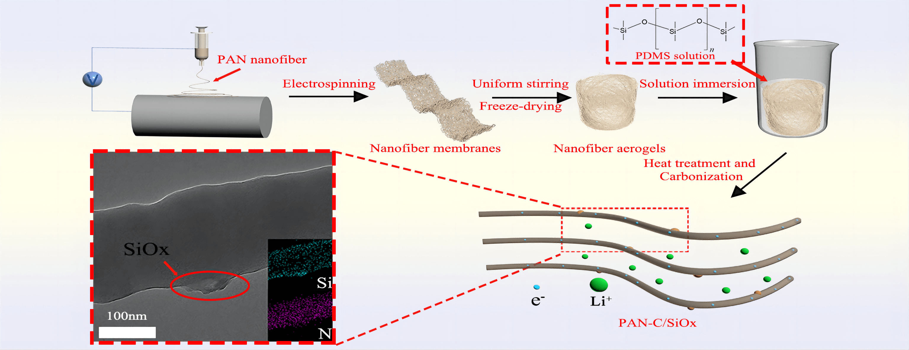
Three-dimensional C/SiOx nanofiber anode was prepared by polydimethylsiloxane (PDMS) and polyacrylonitrile (PAN) as precursors via electrospinning and freeze-drying successfully. In contrast to conventional carbon covering Si-based anode materials, the C/SiOx structure is made up of PAN-C, a 3D carbon substance, and SiOx loading steadily on PAN-C. The PAN carbon nanofibers and loaded SiOx from pyrolyzed PDMS give increased conductivity and a stable complex structure. When employed as lithium-ion batteries (LIBs) anode materials, C/SiOx-1% composites were discovered to have an extremely high lithium storage capacity and good cycle performance. At a current density of 100 mA/g, its reversible capacity remained at 761 mA/h after 50 charge-discharge cycles and at 670 mA/h after 200 cycles. The C/SiOx-1% composite aerogel is a particularly intriguing anode candidate for high-performance LIBs due to these appealing qualities.Graphic Abstract
Keywords
Non-renewable fossil fuels such as coal and oil have not yet been able to supply all of the energy needed by human society due to the world’s population growth and rising energy consumption. Because of this, ecologically friendly and sustainable electricity sources are quite popular and are utilized in a variety of gadgets, including electric cars (EV), hybrid electric vehicles (HEV), and the space shuttle, as well as mobile phones and video cameras. [1]. Lithium-ion batteries (LIBs), one of the most significant energy storage devices, have excellent performance, including high specific energy, advanced energy density, long cycle life, and low self-discharge rate, having occupied a significant portion of the market at the moment. One of the most widely used materials for LIBs anodes is graphite. Graphite, however, falls short of meeting the requirements for high-energy consumption equipment due to its poor rate performance and low specific capacity (372 mA h·g−1) and is constrained by the bottleneck of high-quality applications.
Si, Ge, and Sn are highlighted as alloying anode materials with excellent theoretical specific capacities [2]. Due to the excellent lithium storage properties of Li22Si5, Si is one of the most promising anode materials, having an ultrahigh theoretical specific capacity of 4200 mA h·g−1 [3]. However, the lithiation and de-lithiation processes of silicon frequently result in significant volume expansion of silicon (>300%), which causes the active material to disintegrate and fall off [4]. What’s worse is that the volume change would constantly create the thick solid electrolyte interphase (SEI) on the anode’s surface, preventing Li+ from migrating while also causing the electrolyte to decompose and generating waste from the lithium source [5].
Because there are more atoms on the surface of the nanostructure, it can somewhat enhance the volume effect of silicon. More space for outward expansion could significantly lessen the material’s inherent stress [3,6]. A variety of silicon nanomaterials have blossomed in recent decades, including zero-dimensional nanospheres [7], one-dimensional nanowires [8], two-dimensional nanotubes [9], and porous silicon [10]. It is a fact that these Si nanomaterials do relieve the volume change but poor cyclical stability and unstable SEI film are still unavoidable problems [11]. Carbon is an economical and environmentally friendly anode material. It delivers satisfactory electrical conductivity and mechanical properties [12–14]. The C/Si composites are the most frequently reported among many Si-based composite materials [15–17] and have been demonstrated to efficiently alleviate the volume effect and improve electrical conductivity. Utilizing different carbon sources graphene [18], CNT [19], biomass carbon [20] by ball milling, wet chemistry, and others are currently relatively in-depth and extensive research directions. However, electrospinning may be a simpler and more affordable method to generate the anticipated structure of Si/C composites when balancing the cost of synthesis with precise control over structural morphology [21].
PAN is frequently used as an electrospinning material because of its high electrostatic constant and great graphitization ability at high temperatures. It is a very suitable precursor of carbon nanofibers [22–24]. It has been reported once that PAN nanofibers were filled with silicon/silica nanoparticles by the electrospinning method [25,26]. PAN nanofibers do have a role in preventing Si from coming into direct contact with electrolytes. However, they were unable to effectively handle the agglomeration of nanoparticles. To create porous PAN carbon fiber composites and improve electrochemical capacitance performance, Kim et al. added TEOS to the PAN spinning solution [27]. In order to further prepare PAN/SiO2 hybrid fibers, Pirzada developed a sol-gel synthesis method that included electrospinning technology. Relevant impact aspects regarding the content of SiO2 were also examined. [28]. The non-cluster axial one-dimensional nanofiber structures created by electrospinning can reduce the Li+ transport distance and increase electron conduction [29], as evidenced by the SiNP@C core-shell 1D fiber, which was prepared via the dual-nozzle coaxial electrospinning method proposed by Choi (Fig. 1) [30]. Electrochemical impedance spectroscopy (EIS) plots of SiNP@C are almost overlapping completely even though after hundreds of cycles. The exceptional stability of anode materials without the significant impact from the volume effect of Si is evidenced by the fact that the charge transfer resistance and ionic diffusion rate have not changed.
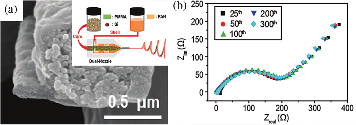
Figure 1: Cross-sectional SEM view of a single SiNP@C (a). Schematic illustration of the electrospinning process (a-illustration). Impedance spectra of SiNP@C at the different cycles (b) “Reproduced with permission of Ref. [25], Copyright of © 2012, American Chemical Society”
The low density of aerogels performs a stable self-supporting network and rich pore structure [14], assembling the advantages of the preparation process, environmental compatibility, biodegradation, and energy storage performance into an integration [25,31–33]. Aerogels are widely used in the various fields of flame-retardant [34], adsorption [35], sensing [36], and energy storage [37]. Theoretically, the porous honeycomb structure of aerogel can buffer the structural deformation of Si-based anode materials, additionally contributing to the rapid infiltration of the electrolyte and the rapid transport of ions [38,39].
There are many modification methods for aerogel, including the gas-phase chemical method [40], and photothermal curing [41]. In this study, polydimethylsiloxane (PDMS) was selected as the silicon source via solution soaking and employed as a three-dimensional (3D) conductive carbon scaffold. To create C/SiOx composite aerogels, pre-oxidation and carbonization treatment are then used. It should be mentioned that evaluating the structure and characteristics of PAN carbon nanofibers requires a pre-oxidation procedure. The linear molecular chain in PAN gradually changes throughout the pre-oxidation treatment into a heat-resistant trapezoidal shape that provides thermodynamic stability under the ensuing high-temperature carbonization [22].
2.1 Preparation and Characterizations of C/SiOx Anode
By mechanically stirring, PAN was dissolved in the subsequent electrospinning solution, N, N-Dimethylformamide (DMF). The following specific electrospinning parameters are set: a 15 cm needle-to-collector distance, a 20 kV variable high-voltage power supply, and a flow rate of 0.6 ml/h. Heat treatment at 60°C was used to stabilize the PAN nanofibers that were electrospun.
After that, 0.6 g PAN nanofibers were homogeneously dispersed into the water/tertbutanol solution (volume ratio of 4:1) through the high-speed homogenizer. Subsequently, the prepared dispersions were frozen in the fridge and then the frozen samples were freeze-dried via a lyophilizer. The PAN aerogels were immersed in the different concentrations of x% PDMS (0.1, 0.5, 1, 2, 5 wt%) for 5 min. (because of the abundant space in the aerogel, PDMS solution can quickly fill the entire aerogel) The corresponding x% PDMS solutions were prepared by mixing the PDMS prepolymer and thermal curing agent (mass ratio of 10:1) in n-hexane. Then the PAN@PDMS aerogels were stabilized via heat treatment at 100°C for 2 h.
Refer to literature related to the pre-oxidation of electrospinning PAN fibers [22]. 250°C was selected as the pre-oxidation temperature and 800°C was the carbonization temperature. The PAN@PDMS aerogels are carbonized and form final products which are abbreviated as C/SiOx-x% aerogels (0.1, 0.5, 1, 2, 5 wt%) [12]. The brief chart of the preparation process and the structure of nanofiber aerogel are shown in Fig. 2.
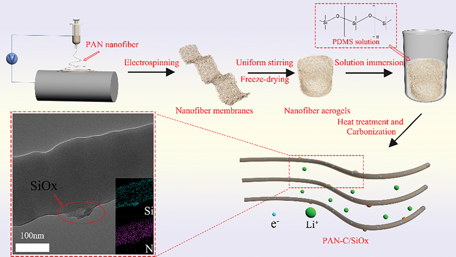
Figure 2: Structural schematic diagram of C/SiOx aerogel and its lithiation process
The microstructure and morphologies of the C/SiOx aerogels were investigated via a high-resolution transmission electron microscope (HRTEM, JEM-2100F, Japan) and field-emission scanning electron microscope (FE-SEM, Hitachi S-4700, Japan). The atomic states and chemical structure of the aerogels were studied via attenuated X-ray photoelectron spectroscopy (XPS, Thermo Scientific K-Alpha, USA) and total reflectance Fourier transform infrared spectroscopy in the spectral range of 4000–400 cm−1 (ATR-FTIR, Nicolet 6700, Germany). X-ray diffraction was performed to determine the phase compositions (XRD, X’Pert PRO, Netherlands). Raman spectroscopy (532 nm wavelength) was used to investigate the graphitization of C/SiOx aerogel (Raman Microscope, Renishaw InVia). The special surface area and pore size distribution were determined by the Brunauer–Emmett–Teller (BET, ASAP 2460, USA). The sample was vacuum-dried at 300°C for 12 h, and nitrogen was used as the adsorbent to obtain the nitrogen adsorption and desorption curve which was deduced subsequently to get the specific surface area and pore size distribution.
Without the addition of polymer binders and electronic conductors, the C/SiOx slurry was thoroughly mixed with N-Methylpyrrolidone (NMP) and pasted onto the 12 mm diameter nickel foam (which had been weighed). After vacuum drying for 12 h at 60°C, another piece of nickel foam was wrapped and pressed, and the loaded mass needed to be weighed. The electrolyte contains 1.0% vinylene carbonate (VC), 5.0% fluoroethylene carbonate (FEC), and 1M LiPF6 in EC/DEC (1:1 Vol%).
By putting together CR2025 coin cells, the electrochemical evaluation of the C/SiOx anode was carried out. Both the counter electrode and the reference electrode were made of lithium metal foil. Lithium metal has a 15 mm diameter and a 0.5 mm thickness, respectively. Between the positive and negative electrodes is a separate film called 2325 Celgard which is 25 um thick and composed of polypropylene. Over a voltage range of 0.01–3.0 V, the cells were galvanostatically charged and discharged (Battery Testing System, Neware CT-4008-5V10Ma-164). Over the voltage range of 0.01–3.0 V, cyclic voltammetry (CV) measurements were carried out at a scanning rate of 0.1 mV/s (Electrochemical Workstation, RST5202F). At the same electrochemical workstation, the electrochemical impedance spectrum (EIS) was measured at frequencies ranging from 0.01 to 100000 Hz, with an amplitude of 5 mV. The electrochemical activation of a newly built battery typically involves five cycles of charge/discharge at a modest current density of 50 mA g−1 in order to activate the positive and negative components. By contrasting the impedance of activated cells with those of inactive cells, EIS analysis can be utilized to examine the variations in the electrochemical reaction kinetics.
3.1 Structure Characterization of the C/SiOx Aerogels
The SEM pictures of the PAN/SiOx-0% aerogel from before carbonization are shown in Fig. 3. The fibers entangle with one another but leave enough spaces, which is favorable to the penetration of electrolytes and can reduce the Li+ transmission distance, resulting in a three-dimensional network structure with a fluffy shape [42].
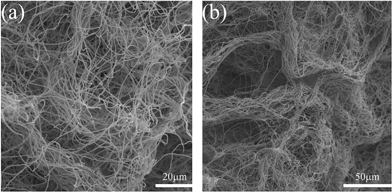
Figure 3: SEM images of PAN/SiOx-0% nanofibers aerogel before carbonization
Fig. 4 show the SEM images of C/SiOx aerogels made by different PDMS wt% contents. Notably, the aggregation state of the fiber changed significantly as the concentration of PDMS solution increased. The aerogels from C/SiOx-0% to C/SiOx-2% all show a relatively good 3D network structure, but C/SiOx-5% express enormous irregular block structures [25]. Figs. 5a–5c and Fig. S1 illustrate how the fiber bundles gradually manifest into irregular aggregates like C/SiOx-5%. The excessive PDMS solution that is producing an ever-increasing SiOx burden is the blame (Table S1). However, the stronger thermal crosslinking reaction on the fibers damages the original 3D network structure, causing the aggregation states of the fibers to shift from entanglement to tight adhesion and even coalesce into irregular solids.
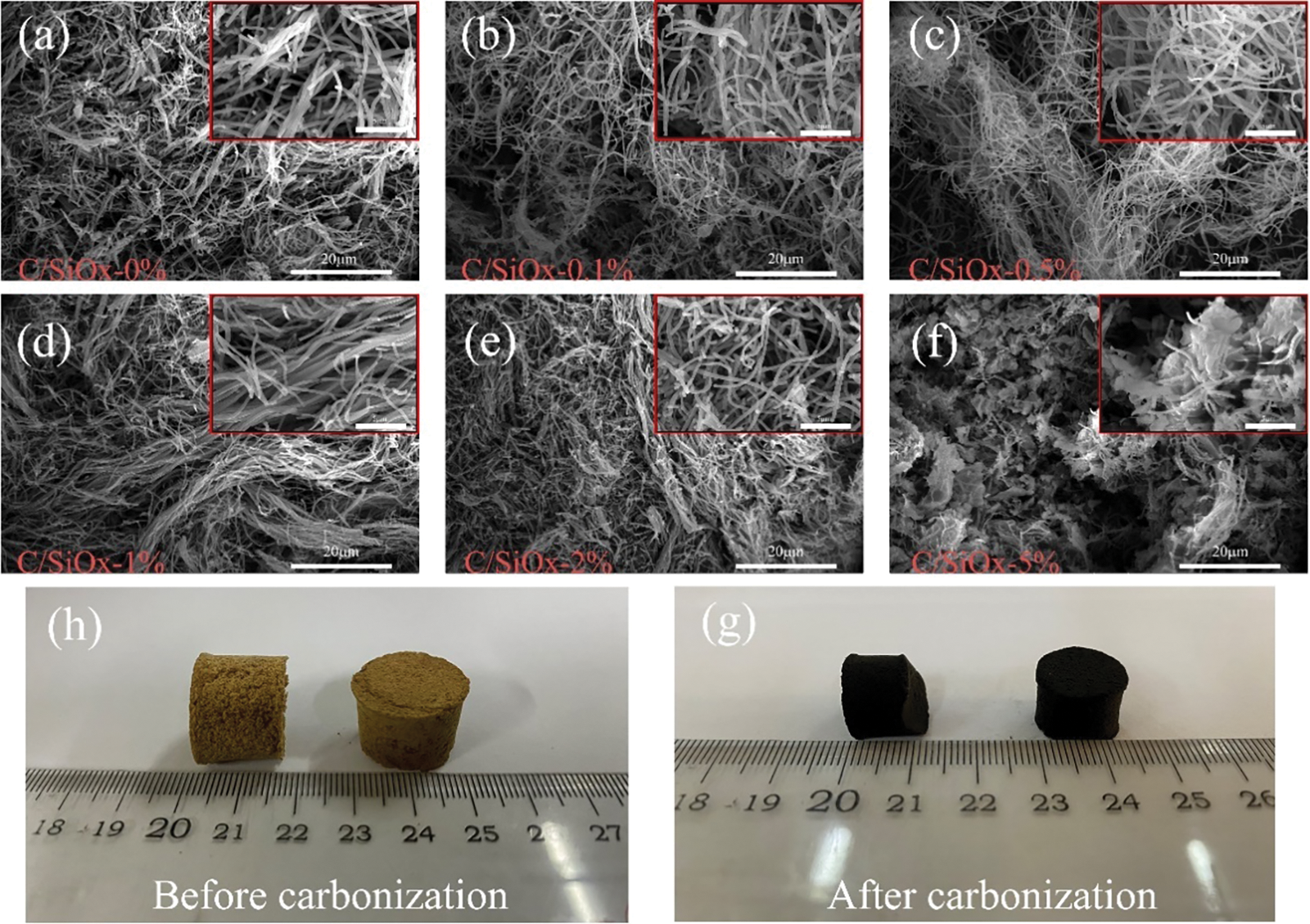
Figure 4: SEM images of C/SiOx nanofibers aerogels made from different PDMS wt% contents: (a) 0%, (b) 0.1%, (c) 0.5%, (d) 1%, (e) 2%, (f) 5%. And the physical maps of C/SiOx aerogels before carbonization (h) and after carbonization (g)
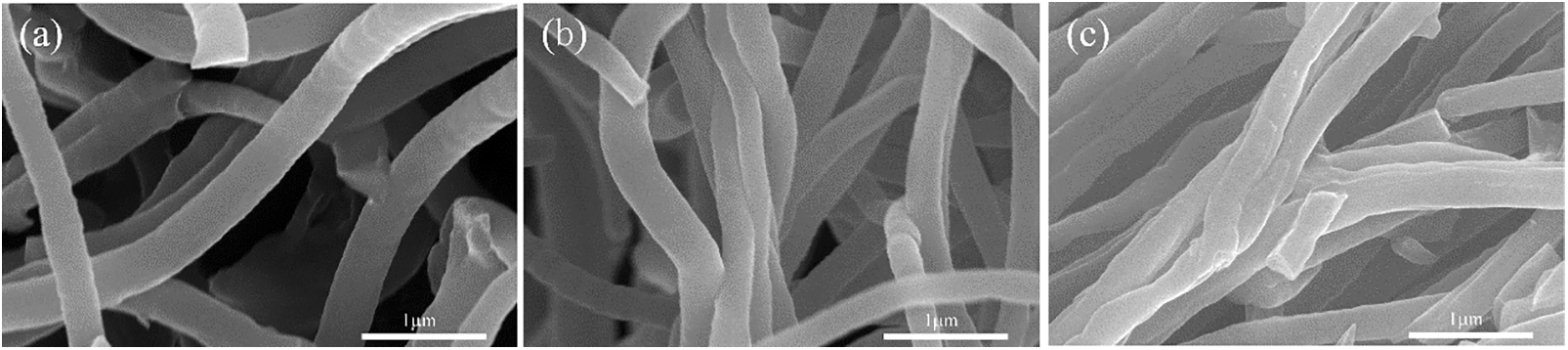
Figure 5: SEM images of the C/SiOx fibers bundle transforming from entanglement to close adhesion: (a) 0%, (b) 0.1%, (c) 1%
During the pre-oxidation and carbonization, the C-C liner molecular of PAN evolved from the linear structure into the trapezoidal structure. The physical images as displayed in Figs. 4h, 4gallow for intuitive observation of the unique volume decreasing of C/SiOx aerogels. The reported studies suggested that polysiloxanes undergo chain breaking, structural rearrangement, and spillover of small molecular gases between 400°C and 800°C, mainly accompanied by dehydrogenation condensation between Si-CH3 and dehydration of Si-O bonds to form Si-O-Si bonds, which results in the formation of SiOx on the PAN-C [8,43]. The specific equation is as follows [44,45]:
To better determine the specific structure of the composite, we also carried out TEM characterization. The prepared C/SiOx-0% and C/SiOx-1% high-resolution TEM images are shown in Fig. 6. It can be seen that the surface of the C/SiOx-0% nanofiber is full of many micropores due to the overflow of small molecular gases such as HCN and CO during PAN carbonation [46]. But C/SiOx-1% shows a rough surface and has no obvious holes. Combined with the EDS result of Fig. 7, N and O atoms were distributed uniformly throughout the nanofiber, while Si was predominantly localized on the surface of the nanofiber. It is reasonable to assume that PAN-C serves as the carbon substance of C/SiOx-1%, and that SiOx is uniformly distributed over PAN-C nanofibers.
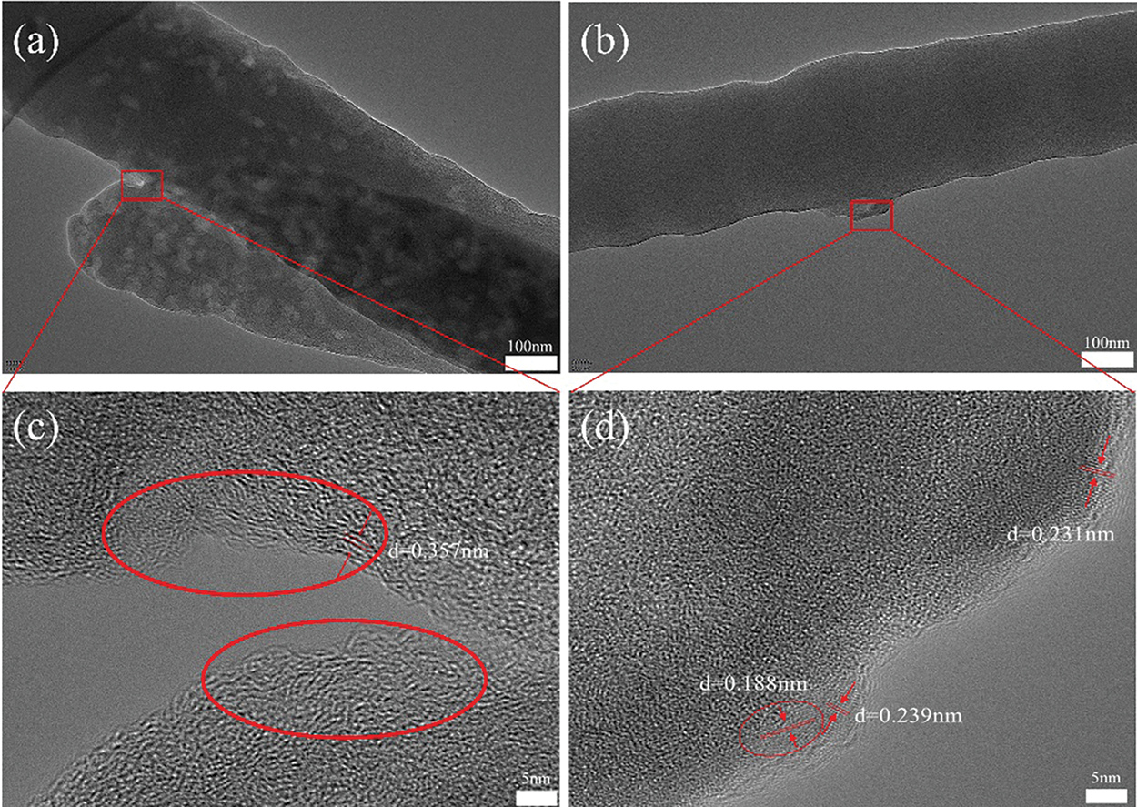
Figure 6: TEM images of C/SiOx-0% (a, c) and C/SiOx-1% (b, d)
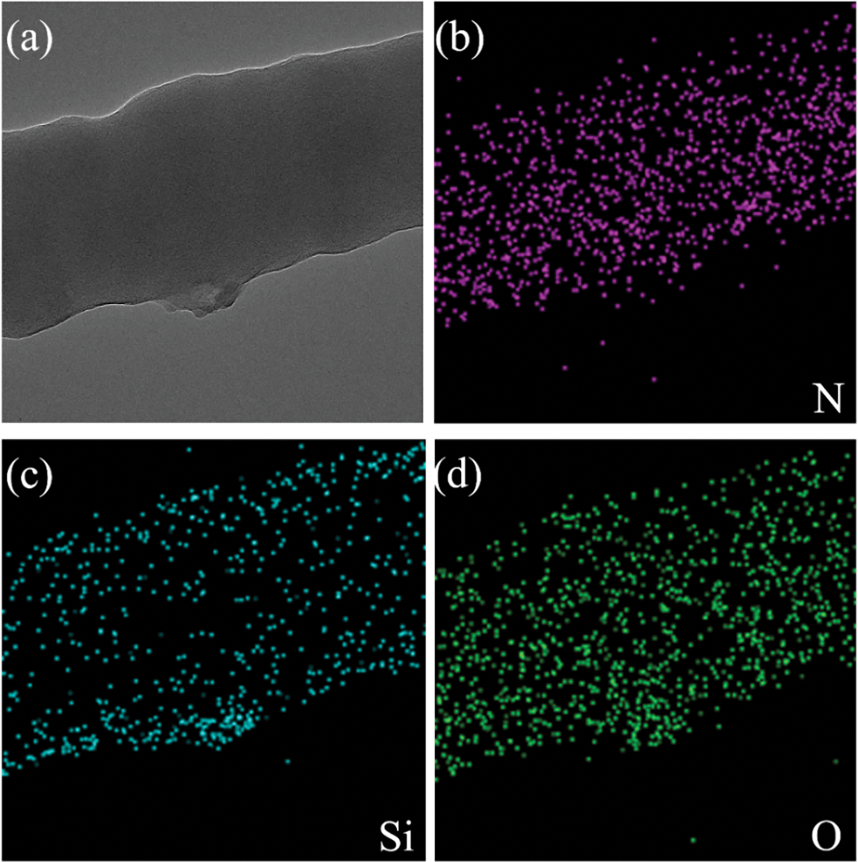
Figure 7: TEM image of C/SiOx-1% (a), and the corresponding elemental mapping images (b–d)
As shown in Fig. S2, PAN-C is mainly amorphous carbon material. But there are a few ordered microcrystalline as in the red circles in Fig. 6c. It is distinct from completely disordered amorphous carbon in other areas. Such turbostratic microstructure consists of short-range ordered parallel hexagonal layers with a calculated 0.357 nm plane distance, which is corresponding to the (002) crystal plane of graphite-C [47]. These small amounts of graphite microcrystals may be formed by the rearrangement and cyclization of PAN molecular chains during the carbonization process. The graphite microcrystalline can facilitate Li+ rapidly to migrate to other regions of the carbon matrix and improve the rate performance of LIBs. Additionally, PAN-C nanofiber is rich in nitrogen, and oxygen elements. These heteroelements can improve electrochemical activity and provide extra lithium reaction sites.
As for C/SiOx-1%, the SiOx is mostly amorphous and evenly distributed on the surface of the fiber. These large quantities of amorphous SiO2 can fully contact the electrolyte, playing a good electrochemical performance. Additionally, some crystal fragments are existing with 0.18 and 0.23 nm crystal plane distances, respectively, corresponding to the (111) and (220) crystalline planes of Si (PDF:27-1402) [10]. In the absence of a designed reduction treatment, the existence of Si microcrystalline may be attributed to the reduction of SiO2 by HCN and NH3 [15].
Specifically, it can be discovered from Fig. 8 that C/SiOx-0% have strong absorption peaks at 1976 and 2200 cm−1 standing for C≡C, C≡N, and wide peaks at 1740 and 1660 cm−1 referring to C=O, C=N, which indicating those oxidative cross-linking reactions between molecular chains occur during pre-oxidation and carbonization, forming conjugate cyclization structure [48]. The FT-IR spectrum of C/SiOx-1% appears the characteristic peaks of Si-C at 780 cm−1 and Si-O-Si bond at 1060 cm−1. However, It should be added that the two sharp small peaks at 2940 and 2870 cm−1 representing the stretching vibration of CH2 disappeared in the FT-IR spectrum of C/SiOx-1%. It may be caused by the condensation reaction between Si-OH and the active H atom of -CH2- to form -O-Si-CR2. And the strong peak at 1650 cm−1 had a redshift because a large number of O atoms from SiOx can provide abundant extra electron pairs and form ρ-π conjugation with C=O bonds thereby reducing the polarity of the bond and making its absorption frequency shift to a lower wave number [49].
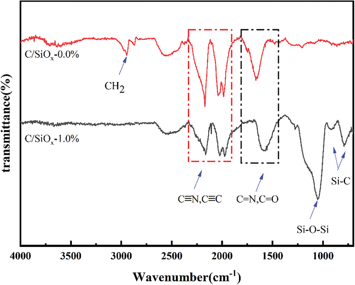
Figure 8: FT-IR spectra of C/SiOx-0% and C/SiOx-1%
XRD characterizations were carried out to clarify the specific phase structure of the material. As shown in Fig. 9a, C/SiOx-0% has a wide diffraction peak of amorphous carbon around 2θ = 20°–40°, indicating that it is mainly amorphous carbon material. The defects in the disordered carbon lattice can provide active sites for Li+ intercalation [50]. There is a sharp and strong peak at 2θ = 26° referring to the (002) crystal plane of the graphite lamellar structure. By calculation, the crystal plane spacing d is 0.338 nm, which is close to the HRTEM result of C/SiOx-0% [48]. As for C/SiOx-1%, there is no strong characteristic peak of graphite crystalline at 2θ = 26° like C/SiOx-0%. We additionally conducted XRD tests on amorphous SiO2 and found that the diffraction peak of SiO2 was also between 2θ = 20°–30° (Fig. S3). So it is believed that the amorphous SiO2 overlaps with the diffraction peak of carbon, causing the strong peak of graphite at 2θ = 26° to be masked, and making the diffraction peak around 2θ = 20°–30° more extensive. And it is sure for the existence of Si crystal from the characteristic peak at 2θ = 28°, 47°, and 54° according to the silicon PDF#27-1402. Therefore, it can be determined that SiOx is composed of mainly amorphous SiO2 and a small amount of Si crystals.
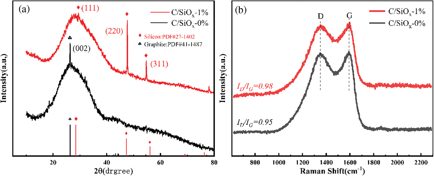
Figure 9: XRD patterns (a) and the Raman spectra of C/SiOx composites (b)
The Raman spectrum is used to further distinguish the carbon structure composition of C/SiOx as shown in Fig. 9b. The D-band (1355 cm−1) and G-band (1590 cm−1) peaks are related to lattice defects of carbon materials and sp2 hybrid C-C bond vibrations, respectively. The Raman curves of C/SiOx-0% and C/SiOx-1% almost coincide while C/SiOx-0% has higher Raman peaks. Besides, ID/IG can be served to characterize the graphitization degree of carbon materials. The larger the ID/IG, the higher the disorder degree of the material. The ID/IG value of C/SiOx-0% is 0.95 by calculation, and less marginally than 0.98 of C/SiOx-1%. The slight graphitization degree drop of C-PAN s can be attributed to doped SiOx [51].
The N2 adsorption-desorption curves and pore size distribution plots are shown in Fig. 10. The SBET, pore volume, and average pore size are summarized in Table 1. The N2 adsorption-desorption isotherm of C/SiOx-0% belongs to the type II isotherm system that increases rapidly at a lower relative pressure. While a small hysteresis loop can be found in Fig. 10b indicating the presence of some mesopores. From the corresponding pore-size distribution, it can be seen that mesopores dominate in the pore system of C/SiOx-1%. The SBET of C/SiOx-0% is 13.7 m²/g, which is slightly higher than C/SiOx-1%.
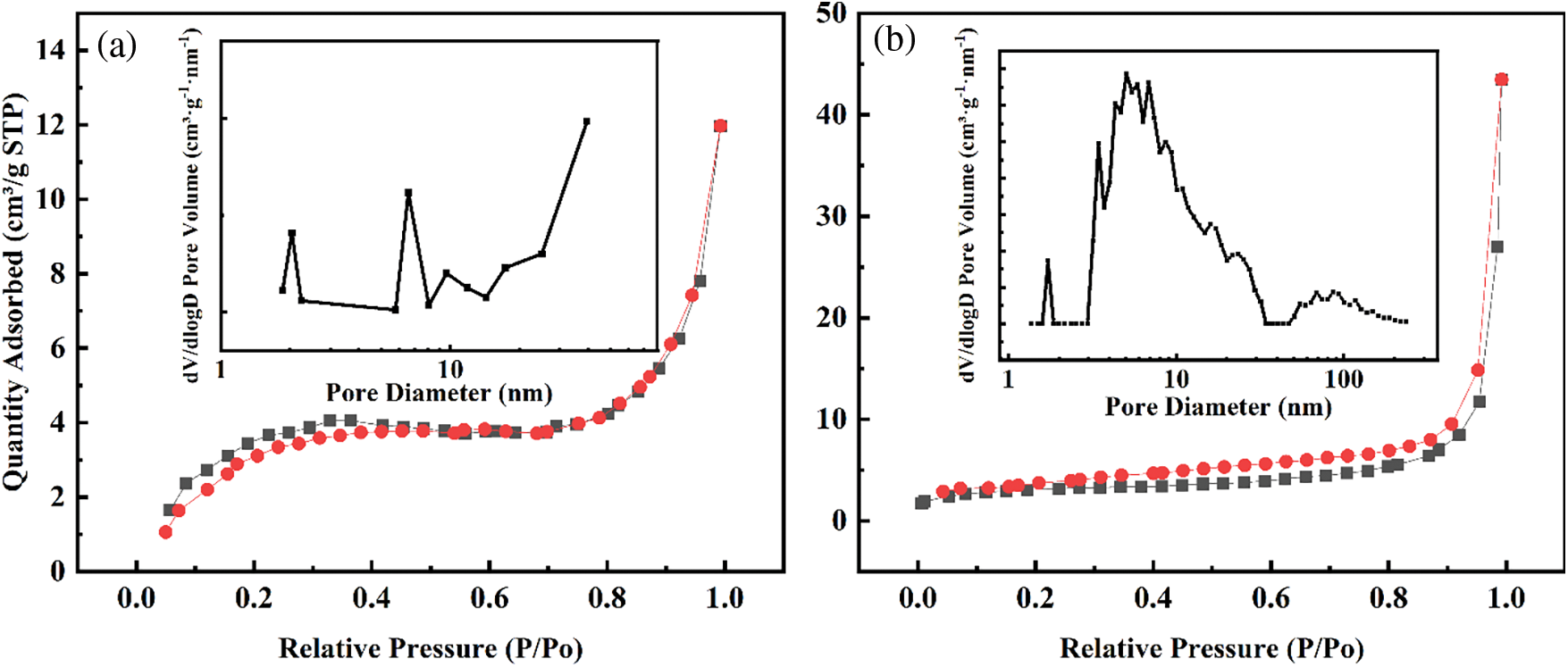
Figure 10: Nitrogen adsorption-desorption isotherms and pore size distribution plots of (a) C/SiOx-0% and (b) C/SiOx-1%

According to Fig. 11, the full spectrum of C/SiOx-1% having O 1s, N 1s, C 1s, Si 2s and Si 2p characteristic peaks at about 532, 400, 284, 154 and 103 eV, respectively. The semi-quantitative atom content of XPS analysis is shown in Table 1. Firstly, C/SiOx-0% is rich in N and O. These heteroelements can improve electrochemical activity and provide extra reaction sites. Secondly, the Si:O atomic content ratio of C/SiOx-1% is 0.44:1 (The O element of the PAN copolymer unit was deducted), which is close to the SiO2 (the theoretical atomic ratio is 0.50:1). The higher oxygen element content of C/SiOx-1% is good at conductivity improvement and reduces charge transfer resistance. Fig. 11b shows the high-resolution spectrum of the Si 2p orbital. It can be seen that the binding energy of pure SiO2 is 104 eV while that of C/SiOx drops to 103 eV [52]. Fig. 11c shows the high-resolution spectrum of O 1s orbital. The characteristic peak of 533 eV represents Si-O of SiO2. Similar to the Si 2p orbital, the O 1s orbital of C/SiOx also presents a light redshift, the binding energy of Si-O decreasing from 533 to 532 eV. It is noteworthy that C/SiOx-0% has a weak but wide characteristic peak around 531 eV represented by a small amount of C=O and C-O ketone carbonyl and ester groups [32]. Analyzing in combination with Figs. 11b, 11c, it can be concluded that the abundant electron cloud on graphite attracts the highly electronegative O atoms. Therefore Si-O bonding energy of SiOx shifts to the lower binding energy, suggesting that there is t good interaction between the SiOx and C-PAN graphite carbon layer [31].
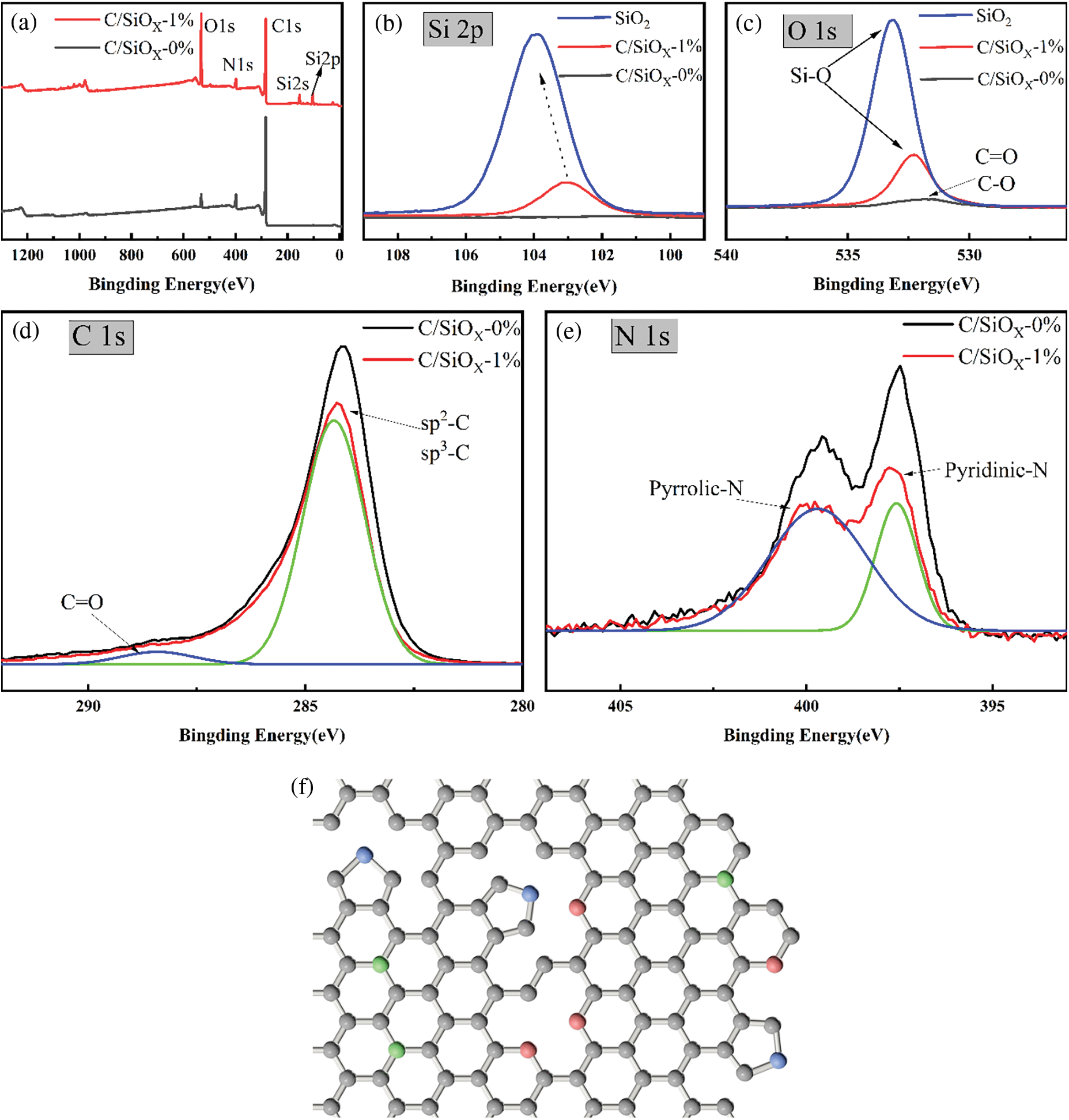
Figure 11: XPS spectra of C/SiOx -0%, C/SiOx-1% and SiO2: (a) full spectrum, (b) Si 2p orbital, (c) O 1s orbital, (d) C 1s orbital, (e) N 1s orbital. (f) Schematic illustration of the forms of nitrogen in N-doped carbon materials
It is similar for both the C/SiOx-0% and C/SiOx-1% about the C 1s and N 1s XPS spectra. The blue and green peaks represent different groups after peak fitting. The distinct peak of 284 eV in C 1s spectra stands for sp2/sp3-C hybrid orbitals and 288 eV for the C=O bond. The only difference between C/SiOx-0% and C/SiOx-1%is that the sp2/sp3-C peak of PAN-C is stronger than C/SiOx due to the higher carbon content [53]. The N 1s XPS spectra contain characteristic peaks of pyridine-N (397 eV) and pyrrole-N (399 eV) [54]. A large number of N atoms originating from PAN are embedded in the defects or edges of the graphite layer during high-temperature carbonization. As shown in Fig. 11f, the red spheres represent pyridinic N atoms (N-6), green spheres represent quaternary N atoms (N-Q), and blue spheres represent pyrrolic N atoms (N-5). Heterocyclic N atoms can provide diverse π conjugated systems, and the left lone electron pair can adsorb Li+. The abundant nitrogen atoms can also contribute access to the pseudocapacitance effect, which is of great help to the lithium storage capacity for the C/SiOx electrode [55].
3.2 Electrochemical Performance of the C/SiOx
Galvanostatic charge-discharge experiments were carried out at a current density of 100 mA·g−1 within a voltage window of 0.01–3.00 V to evaluate the electrochemical performance of C/SiOx anode materials as shown in Fig. 12 and the detailed data of each sample is displayed in Table 2. It is obvious that, compared with the other counterparts, C/SiOx-1% showed the best lithium storage performance. Its initial discharge/charge specific capacity is reaching up to 1940/1320 mA h·g−1. After 50 cycles, its reversible specific capacity is stable at 780 mA h·g−1 and still has 670 after the 200 cycles.
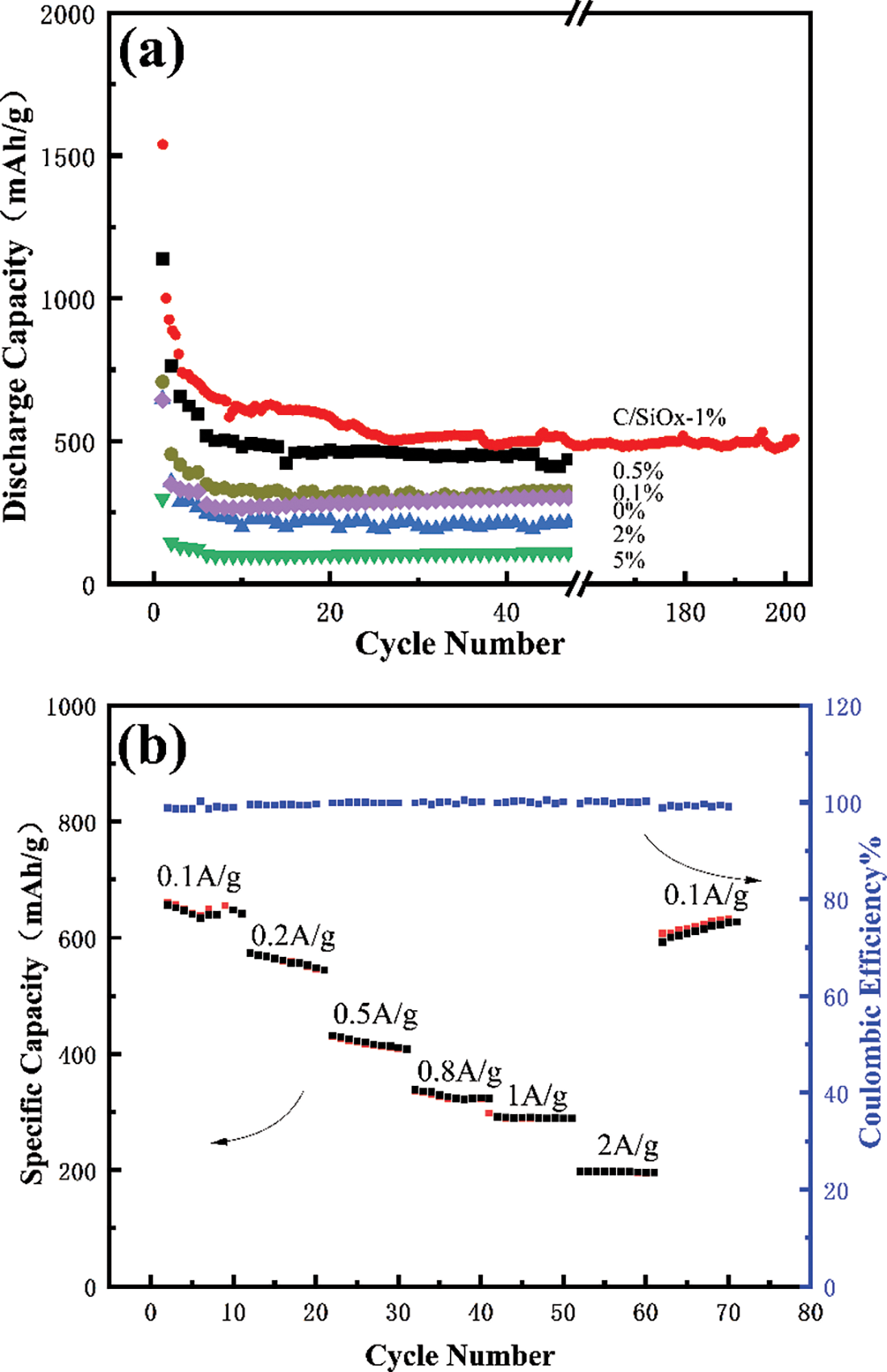
Figure 12: Cycle performance of C/SiOx anodes at a current density of 100 mA·g−1 (a), and the rate capability of C/SiOx-1% (b)

This is a trend that with the increase of SiOx, the specific capacity increased gradually from 301 mA h·g−1 of C/SiOx-0% to 781 mA h·g−1 of C/SiOx-1%. Benefiting from the three-dimensional conductive carbon networks, C/SiOx-0% possesses good battery performance as a self-supporting skeleton and is close to the theoretical specific capacity of graphite carbon (372 mA h·g−1). Besides, the conductive improved SiOx fully plays its own high lithium storage ability and the overall electrochemical performance of the material improves.
However, As the PDMS solution concentration continues to grow, the specific capacity decreased instead from 217 mA h·g−1 of C/SiOx-2% to 112 mA h·g−1 of C/SiOx-5%, which is even far lower than the C/SiOx-0%. This may be because excessive SiOx accumulation on carbon fiber destroys the original 3D carbon network structure and its poor electrical conductivity exerts a negative effect on the material.
Moreover, the rate capability of the C/SiOx-1% was also investigated. Fig. 12b showed the rate plots at various current densities. The specific capacity presented a regular decline trend (from 682 mA h·g−1 at 0.1 A g−1, 596 mA h·g−1 at 0.2 A g−1, 456 mA h·g−1 at 0.5 A g−1, 353 mA h·g−1 at 0.8 A g−1, 298 mA h·g−1 at 1 A g−1, to 215 mA h·g−1 at 2 A g−1, respectively). The regular decrease is caused by the limitation of Li+ diffusion in the solid phase. When the current density switches back to 0.1 A g−1, the discharge capacity can rapidly return to 622 mA h·g−1. The coulombic efficiency of the material can be maintained above 99% at different rates, expressing outstanding rate performance [30].
Figs. 13a, 13b are the charge-discharge curves of C/SiOx-0% and C/SiOx-1%, respectively. A steep slope of the initial discharge process in Fig. 13a between 1.2 to 1.4 V indicates the decomposition of the electrolyte. Then a large discharge platform of about 0.7 V stands for the formation of SEI film. By associating the charge-discharge curves of the 1st, 2nd, 3rd, 30th and 50th cycles, we found that the specific capacity decreased slightly in the first 30 cycles, mainly occurring between 1–2 V.
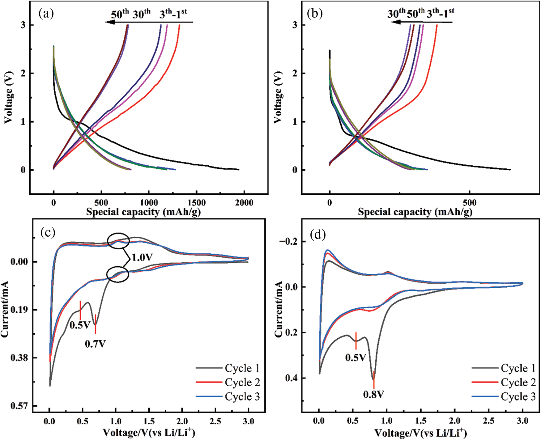
Figure 13: Charge–discharge curves of C/SiOx-0% (a) and C/SiOx-1% (b). CV curves of C/SiOx-1% (c) and amorphous SiO2 (d)
As for C/SiOx-1%, there is an obvious platform around 1 V in the initial discharge process that disappeared in the next cycle, which is contributed by the reduction decomposition of SiO2. It is worth noting that the capacity loss from the third cycle to the 30th cycle may be due to the instability of SiOx. The reason is that the 1–1.5 V potential range is dominated by diffusion behavior, which can also be confirmed by the pseudocapacitance contribution diagram. But the charge-discharge curves of the C/SiOx-1% coincide almost at the 30th and 50th cycles, which indicates that after dozens of charge-discharge cycles, SiOx materials gradually tend to be stable and deliver good cyclic stability.
To further explore the electrochemical mechanism of C/SiOx-1%, we analyzed further combined with the CV curve. In Fig. 13c, there is a reduction peak of about 1.0 V (circled by black circles) during the cathode scan which means the reaction of SiO2 with Li+ to form Si and Li2Si2O5, and then the corresponding oxidation peak represents the Li2Si2O5 reversibly transforming to SiO2, which is consistent with the mechanism of the amorphous SiO2 (Fig. 13d). Then a significant reduction peak at 0.7 V that disappears after the first cycle represents the decomposition of the electrolyte and the reduction of substantial SiO2 to irreversible Li2O and Li4SiO4. A small peak at 0.5 V is attributed to SEI film formation. A huge cathode peak at 0.1 V refers to a large number of Li embedded in the amorphous carbon layer and released in subsequent anode scanning. However, it is hard to distinguish the peak of Si-Li because it is very close to that of carbon. Therefore the whole mechanism of lithiation/de-lithiation can be concluded as follows:
To better inspect the electrochemical reaction kinetics differences, C/SiOx composites were conducted with EIS and analyzed via Rs[C[Rct Wo]] equivalent circuit model. The Rs in the high-frequency region indicate the electrolyte impedance, Rct (charge transfer impedance) in the middle frequency region is the resistance of charge transmission at the interface between electrode material and electrolyte, and Zw (Warburg impedance) in the low-frequency region stands for the diffusion of ions. The smaller Rct value reflects better electron/ion transport ability and effective electrochemistry reaction.
As shown in Figs. 14a, 14b and Table 3, the unactivated C/SiOx-0% and C/SiOx-1% are a bit similar. After the electrochemistry activation, C/SiOx-0% displays a standard straight line of semi-infinite linear diffusion in the lower frequency, while C/SiOx-1% displays a higher slope of the line and indicates that is controlled by both electrochemical polarization and concentration polarization. The Rct of C/SiOx-0% remains unchanged after activation. Buthean interesting thing is that the activated Rcts of C/SiOx-0.1%, C/SiOx-0.5%, and C/SiOx-1% are smaller than that of C/SiOx-0%. The fairly low charge transfer impedance is in favor to accelerate the process of lithium reaction. In addition, we tested the EIS of the C/SiOx-1% at the first and 200 cycles, and the result is shown in Fig. 14c. The shapes of the two curves argenerally similarly, but the Rct of the C/SiOx-1% becomes larger after 200 cycles, which is acceptable and reasonable because SiOx would form irreversible insulating products in the charge-discharge process. But in general, active materials still have electrochemical activity and stability.
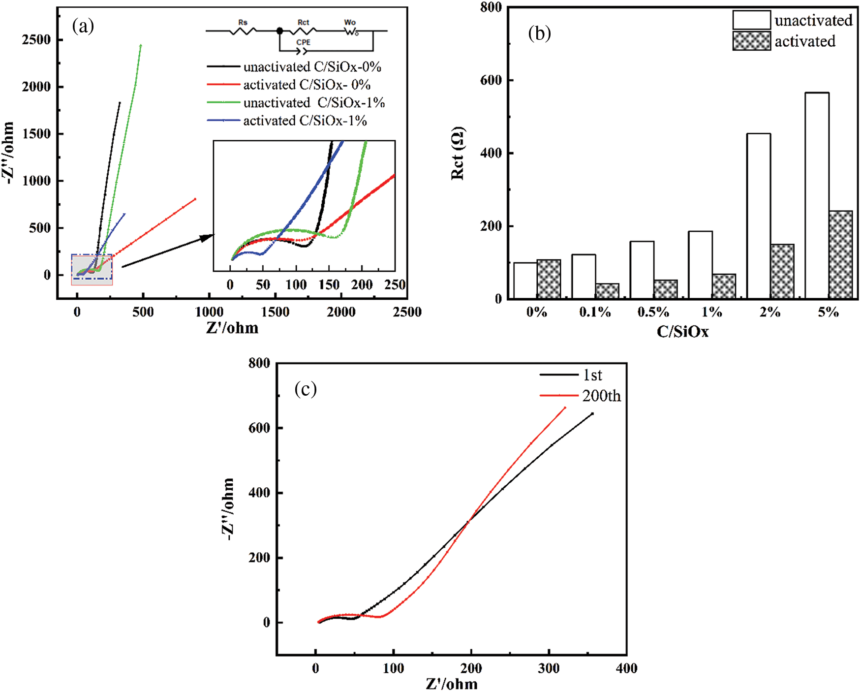
Figure 14: Nyquist plots of the EIS (a), and the upper and lower insets are the corresponding equivalent circuit and the magnification of semicircles, respectively. Histogram of specific Rct numbers of each sample (b). And Nyquist plots at the 1st and 200th cycles of C/SiOx-1.0% (c)

To further investigate the quantitative capacity properties of the C/SiOx-1.0% electrode, CV curves at different scan rates from 0.1 to 1.0 mV·s−1 were measured (Fig. 15a). The two peaks near 1.5 V are selected for analysis. It was found that the b value (the slope of the fitted line) for the two peak currents were 0.63 and 0.79 as shown in Fig. 15b. This implies that the electrochemical kinetics of the C/SiOx-1.0% electrode during the 1–1.5 V potential interval is controlled by pseudocapacitive behavior partly [56]. Typically, Fig. 15c shows the CV curve with a capacitive contribution at a scan rate of 0.5 mV·s−1. The red area is presented as the pseudocapacitance effect [57]. In order to distinguish the pseudocapacitance contribution to the current response of CV curves [58]. As shown in Fig. 15d, the contribution of the pseudocapacitance capacity to the total capacity at different scan rates are 23%, 28%, 34%, 37% and 39%, respectively. Although the contribution of pseudocapacitance increases slightly with the increase in scanning speed, diffusion-control capacitance still accounts for the main contribution [59].
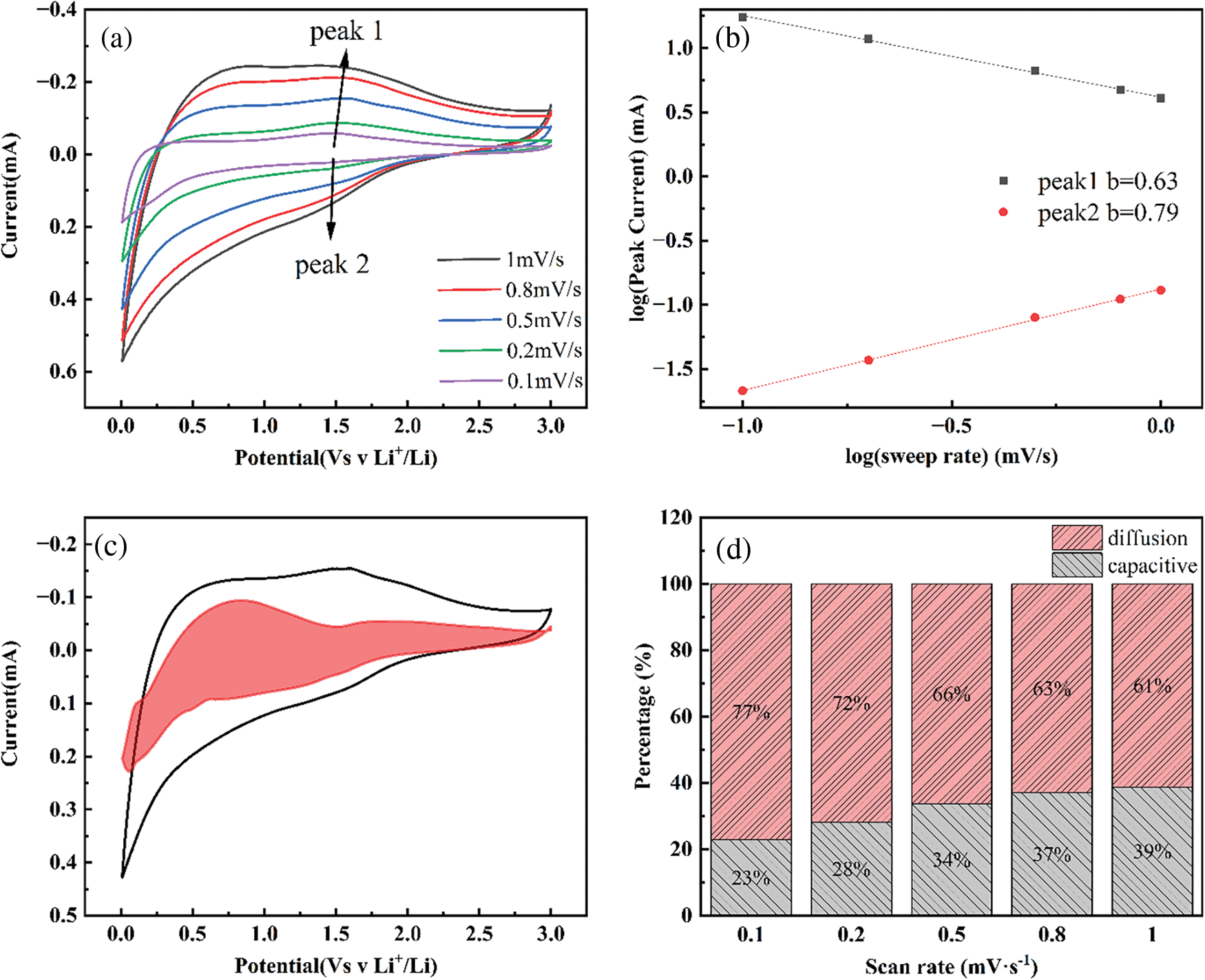
Figure 15: Electrochemical properties of the C/SiOx-1.0% electrode. CV curves at various scan rates (a). Correlations of charging/discharging peak current density (log i) and scan rate (log v) (b). CV response at a scan rate of 0.5 mV·s−1 and the part of capacitive contribution is marked by red region (c). The percentages of capacitive contribution at different scan rates (d)
To better explain the diffusion properties of lithium ions in active materials, we calculated the ion diffusion rate through EIS. The calculation formulas are as follows:
The diagonal line in the low-frequency region is related to the diffusion coefficient (DLi+) of Li+ in the electrode material. The fitting relationship between Z′ and ω−0.5 is shown in Fig. 16 and the linear fitting result is very good. Finally, it can be calculated that the Li ion diffusion coefficient of C/SiOx-1% is 6.55 × 10⁻¹³ cm2·s−1, which is rather higher than that of graphite (3.24 × 10⁻¹⁴ cm2·s−1) [58].
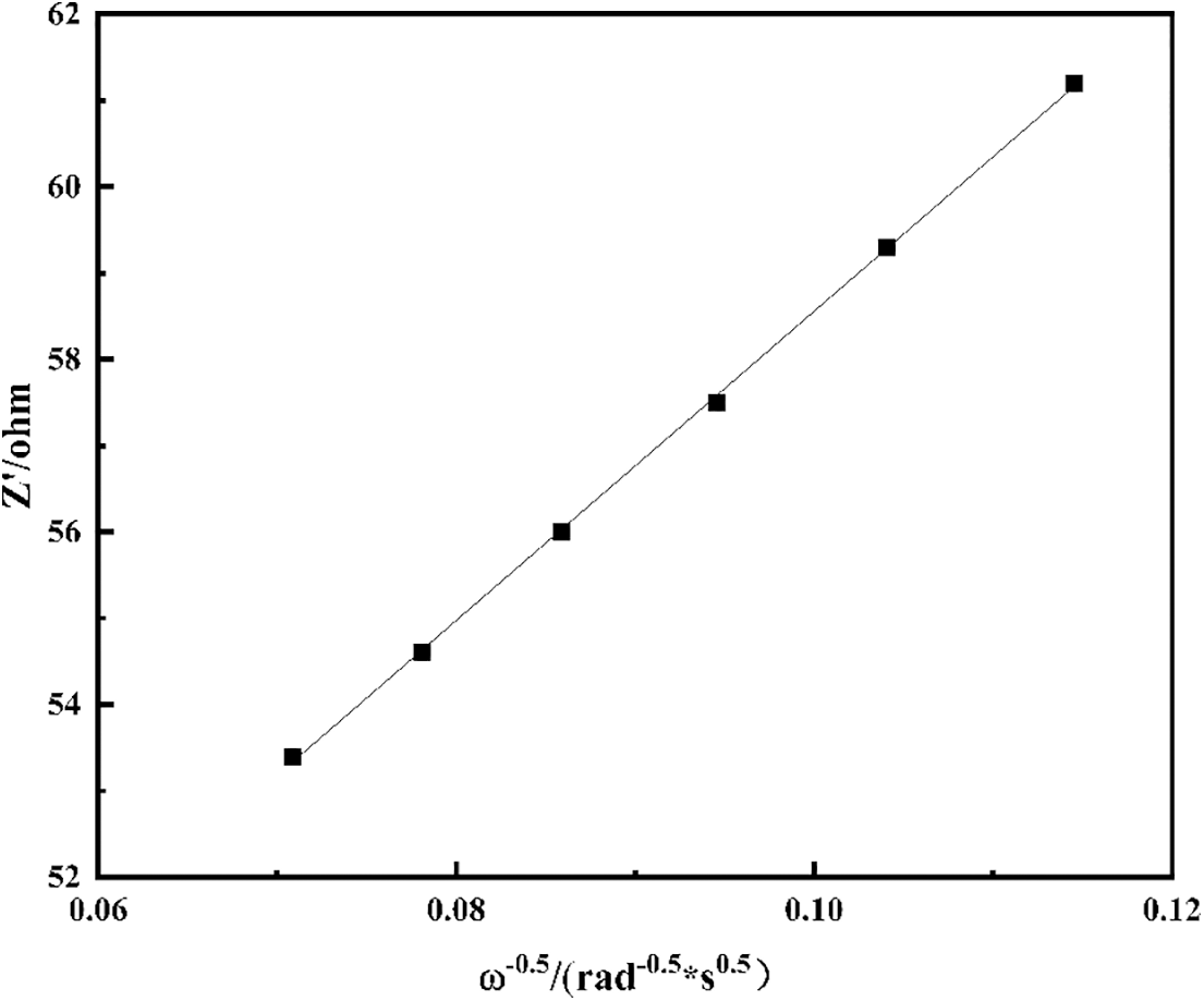
Figure 16: Graph of Z′ plotted against ω−0.5 at the low-frequency region for C/SiOx-1%
In order to investigate the morphological and structural changes of the C/SiOx-1% composite after the lithium de-embedding process. We also disassembled the C/SiOx-1% half-cell, took out the negative electrode, and cleaned it with an organic carbonate solvent. The entire process was carried out in a glove box filled with Ar gas. Prior to SEM characterization, the C/SiOx-1% anode sheets were fully dried in a vacuum drying oven. Figs. 17a, 17b demonstrate that the rough surface of the fiber is the SEI film formed by the decomposition othe f electrolyte. This film can act as a buffer for the volume expansion of SiOx and preserve the fiber’s original structure, as shown by the absence of large-scale fiber fracture. Additionally, as shown in Fig. 17c, the three-dimensional aerogel structure remains very well intact and is very stably adhered to the nickel foam without the addition of binder. And the pore system of aerogel is unaltered, and fiber bundles do not significantly aggregate into clumps. The rich pore structure can significantly increase electrolyte penetration and speed up lithium ion diffusion [60].
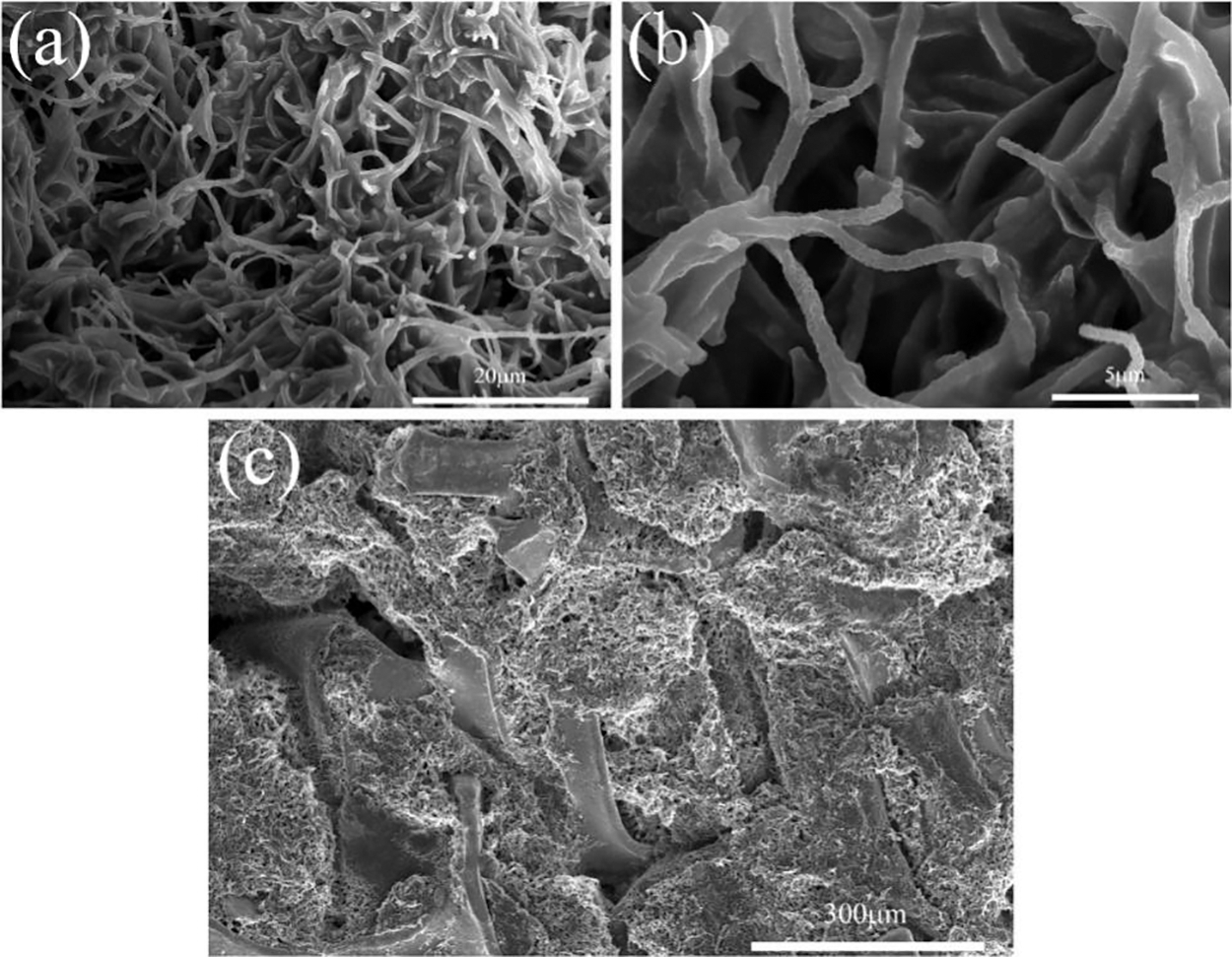
Figure 17: SEM images of C/SiOx-1% anode materials after 200 cycles
Based on the electrochemical performances of the C/SiOx in this work, In order to investigate the morphological and structural changes of the C/SiOx-1% composite after the lithium de-embedding process. We also disassembled the C/SiOx-1% half-cell, took out the negative electrode, and cleaned it with an organic carbonate solvent. The entire process was carried out in a glove box filled with Ar gas. Prior to SEM characterization, the C/SiOx-1% anode sheets were fully dried in a vacuum drying oven. Figs. 17a, 17b demonstrate that the rough surface of the fiber is the SEI film formed by the decomposition othe f electrolyte. This film can act as a buffer for the volume expansion of SiOx and preserve the fiber’s original structure, as shown by the absence of large-scale fiber fracture. Additionally, as shown in Fig. 17c, the three-dimensional aerogel structure remains very well intact and is very stably adhered to the nickel foam without the addition of binder. And the pore system of aerogel is unaltered, and fiber bundles do not significantly aggregate into clumps. The rich pore structure can significantly increase electrolyte penetration and speed up lithium ion diffusion [60].
Based on the electrochemical performances of the C/SiOx in this work, Table 4 summarises other high-performance literature data for comparison. The prepared C/SiOx-1% shows the ultrahigh capacity of 1940 mA h·g−1 at the initial cycle and can maintain 670 mA h·g−1 after 200 cycles, showing superior lithium storage properties compared to those reported in previous literature.

In summary, we have successfully prepared a novel C/SiOx nanofiber aerogel. C/SiOx-1% was found to have the ultrahigh capacity of 1940 mA h·g−1 at the initial discharge/charge cycle and excellent cycle stability. After 200 cycles, the specific capacity maintains 670 mA h·g−1 due to the following advantages:
1. The three-dimensional conductive carbon networks, as a self-supporting skeleton, reply on low electrochemical impedance and excellent conductivity, and contribute to the full penetration of the electrolyte. Li+ can migrate rapidly to the fiber surface even at high current density, showing excellent rate performance.
2. This 3D carbon skeleton avoids the other SiO/C composites reported before that require nanoscale treatment or surface porous structures to increase the effective contact area of SiOx. Different from the common carbon coating process, the conductive improved SiOx is beneficial to contact electrolytes and facilitate lithiation reaction.
3. The PAN/PDMS precursor material has been reported for excellent properties in many other fields. The prospect of multifunctional applications makes it have great development potential.
Funding Statement: We are thankful for the Project Supported by the Zhejiang Provincial Natural Science Foundation of China (GB21031200070) and National Natural Science Foundation of China (C125020173) for the support to this research.
Conflicts of Interest: The authors declare that they have no conflicts of interest to report regarding the present study.
References
1. Krishnaveni, K., Subadevi, R., Sivakumar, M., Raja, M., Prem Kumar, T. (2019). Synthesis and characterization of graphene oxide capped sulfur/polyacrylonitrile composite cathode by simple heat treatment. Journal of Sulfur Chemistry, 40(4), 377–388. https://doi.org/10.1080/17415993.2019.1582655 [Google Scholar] [CrossRef]
2. Balderas-Valadez, R. F., Estévez-Espinoza, J. O., Salazar-Kuri, U., Pacholski, C., Mochan, W. L. et al. (2018). Fabrication of ordered tubular porous silicon structures by colloidal lithography and metal assisted chemical etching: SERS performance of 2D porous silicon structures. Applied Surface Science, 462, 783–790. https://doi.org/10.1016/j.apsusc.2018.08.120 [Google Scholar] [CrossRef]
3. Wang, G. X., Ahn, J. H., Yao, J., Bewlay, S., Liu, H. K. (2004). Nanostructured Si-C composite anodes for lithium-ion batteries. Electrochemistry Communications, 6(7), 689–692. https://doi.org/10.1016/j.elecom.2004.05.010 [Google Scholar] [CrossRef]
4. Liu, Z., Yu, Q., Zhao, Y., He, R., Xu, M. et al. (2019). Silicon oxides: A promising family of anode materials for lithium-ion batteries. Chemical Society Reviews, 48(1), 285–309. https://doi.org/10.1039/C8CS00441B [Google Scholar] [PubMed] [CrossRef]
5. Luo, F., Liu, B., Zheng, J., Chu, G., Zhong, K. et al. (2015). Review-nano-silicon/carbon composite anode materials towards practical application for next generation Li-ion batteries. Journal of the Electrochemical Society, 162(14), 2509–2528. https://doi.org/10.1149/2.0131514jes [Google Scholar] [CrossRef]
6. Cai, W., Zhang, F., Li, B., Yang, Y., Li, Y. (2019). Fabrication of C/SiC/Si composite fibers from helical mesoporous silica and application as lithium ion battery anode. Journal of the Taiwan Institute of Chemical Engineers, 97(4), 489–495. https://doi.org/10.1016/j.jtice.2019.02.021 [Google Scholar] [CrossRef]
7. Lee, S. K., Oh, S. M., Park, E., Scrosati, B., Hassoun, J. et al. (2015). Highly cyclable lithium-sulfur batteries with a dual-type sulfur cathode and a lithiated Si/SiOx nanosphere anode. Nano Letters, 15(5), 2863–2868. https://doi.org/10.1021/nl504460s [Google Scholar] [PubMed] [CrossRef]
8. Wang, J., Wang, H., Zhang, B., Wang, Y., Lu, S. et al. (2015). A stable flexible silicon nanowire array as anode for high-performance lithium-ion batteries. Electrochimica Acta, 176, 321–326. https://doi.org/10.1016/j.electacta.2015.07.001 [Google Scholar] [CrossRef]
9. Castrucci, P., Diociaiuti, M., Tank, C. M., Casciardi, S., Tombolini, F. et al. (2012). Si nanotubes and nanospheres with two-dimensional polycrystalline walls. Nanoscale, 4(16), 5195–5201. https://doi.org/10.1039/c2nr30910f [Google Scholar] [PubMed] [CrossRef]
10. Liang, J., Li, X., Zhu, Y., Guo, C., Qian, Y. (2015). Hydrothermal synthesis of nano-silicon from a silica sol and its use in lithium ion batteries. Nano Research, 8(5), 1497–1504. https://doi.org/10.1007/s12274-014-0633-6 [Google Scholar] [CrossRef]
11. Zhang, Z., Wang, H., Cheng, M., He, Y., Han, X. et al. (2021). Confining invasion directions of Li+ to achieve efficient Si anode material for lithium-ion batteries. Energy Storage Materials, 42, 231–239. https://doi.org/10.1016/j.ensm.2021.07.036 [Google Scholar] [CrossRef]
12. Wu, Y., Reddy, M. V., Chowdari B. V., R., Ramakrishna, S. (2013). Long-term cycling studies on electrospun carbon nanofibers as anode material for lithium ion batteries. ACS Applied Materials & Interfaces, 5(22), 12175–12184. https://doi.org/10.1021/am404216j [Google Scholar] [PubMed] [CrossRef]
13. Yang, H. W., Kang, W. S., Kim, S. J. (2022). A significant enhancement of cycling stability at fast charging rate through incorporation of Li3N into LiF-based SEI in SiOx anode for Li-ion batteries. Electrochimica Acta, 412(1), 140107. https://doi.org/10.1016/j.electacta.2022.140107 [Google Scholar] [CrossRef]
14. Cao, Z., Zheng, X., Qu, Q., Huang, Y., Zheng, H. (2021). Electrolyte design enabling a high-safety and high-performance Si anode with a tailored electrode-electrolyte interphase. Advanced Materials, 33(38), 2103178. https://doi.org/10.1002/adma.202103178 [Google Scholar] [PubMed] [CrossRef]
15. Park, C. M., Choi, W., Hwa, Y., Kim, J. H., Jeong, G. et al. (2010). Characterizations and electrochemical behaviors of disproportionated SiO and its composite for rechargeable Li-ion batteries. Journal of Materials Chemistry, 20(23), 4854–4860. https://doi.org/10.1039/b923926j [Google Scholar] [CrossRef]
16. Tang, J., Dai, X., Wu, F., Mai, Y., Wang, X. et al. (2019). A simple and efficient one-pot synthesis of SiO2 nanotubes with stable structure and controlled aspect ratios for anode materials of lithium-ion batteries. Ionics, 26(2), 639–648. https://doi.org/10.1007/s11581-019-03246-4 [Google Scholar] [CrossRef]
17. Chang, W. S., Park, C. M., Kim, J. H., Kim, Y. U., Jeong, G. et al. (2012). Quartz (SiO2A new energy storage anode material for Li-ion batteries. Energy & Environmental Science, 5(5), 6895–6899. https://doi.org/10.1039/c2ee00003b [Google Scholar] [CrossRef]
18. Shin, J., Park, K., Ryu, W. H., Jung, J. W., Kim, I. D. (2014). Graphene wrapping as a protective clamping layer anchored to carbon nanofibers encapsulating Si nanoparticles for a Li-ion battery anode. Nanoscale, 6(21), 12718–12726. https://doi.org/10.1039/C4NR03173C [Google Scholar] [PubMed] [CrossRef]
19. Xue, Y., Gao, M., Wu, M., Su, D., Guo, X. et al. (2020). A promising hard carbon−soft carbon composite anode with boosting sodium storage performance. ChemElectroChem, 7(19), 4010–4015. https://doi.org/10.1002/celc.202000932 [Google Scholar] [CrossRef]
20. Yu, K. F., Liu, T., Zheng, Q. F., Wang, X. F., Liu, W. P. et al. (2020). Rice husk lignin-based porous carbon and ZnO composite as an anode for high-performance lithium-ion batteries. Journal of Porous Materials, 27(3), 875–882. https://doi.org/10.1007/s10934-019-00824-9 [Google Scholar] [CrossRef]
21. Kumar, P. S., Sundaramurthy, J., Sundarrajan, S., Babu, V. J., Singh, G. et al. (2014). Hierarchical electrospun nanofibers for energy harvesting, production and environmental remediation. Energy & Environmental Science, 7(10), 3192–3222. https://doi.org/10.1039/C4EE00612G [Google Scholar] [CrossRef]
22. Qin, X. H. (2010). Structure and property of electrospinning PAN nanofibers by different preoxidation temperature. Journal of Thermal Analysis Calorimetry, 99(2), 571–575. https://doi.org/10.1007/s10973-009-0126-0 [Google Scholar] [CrossRef]
23. Lee, B. S., Son, S. B., Park, K. M., Lee, G., Oh, K. H. et al. (2012). Effect of pores in hollow carbon nanofibers on their negative electrode properties for a lithium rechargeable battery. ACS Applied Materials & Interfaces, 4(12), 6702–6710. https://doi.org/10.1021/am301873d [Google Scholar] [PubMed] [CrossRef]
24. Kim, C., Yang, K. S., Kojima, M., Yoshida, K., Kim, Y. J. et al. (2006). Fabrication of electrospinning-derived carbon nanofiber webs for the anode material of lithium-ion secondary batteries. Advanced Functional Materials, 16(18), 2393–2397. https://doi.org/10.1002/(ISSN)1616-3028. [Google Scholar] [CrossRef]
25. Si, Y., Fu, Q., Wang, X., Zhu, J., Yu, J. et al. (2015). Superelastic and superhydrophobic nanofiber-assembled cellular aerogels for effective separation of oil/water emulsions. ACS Nano, 9(4), 3791–3799. https://doi.org/10.1021/nn506633b [Google Scholar] [PubMed] [CrossRef]
26. Zhang, X., Ji, L., Toprakci, O., Liang, Y., Alcoutlabi, M. (2011). Electrospun nanofiber-based anodes, cathodes, and separators for advanced lithium-ion batteries. Polymer Reviews, 51(3), 239–264. https://doi.org/10.1080/15583724.2011.593390 [Google Scholar] [CrossRef]
27. Kim, B. H., Yang, K. S., Woo, H. G. (2011). Thin, bendable electrodes consisting of porous carbon nanofibers via the electrospinning of polyacrylonitrile containing tetraethoxy orthosilicate for supercapacitor. Electrochemistry Communications, 13(10), 1042–1046. https://doi.org/10.1016/j.elecom.2011.06.024 [Google Scholar] [CrossRef]
28. Pirzada, T., Arvidson, S. A., Saquing, C. D., Shah, S. S., Khan, S. A. (2014). Hybrid carbon silica nanofibers through sol-gel electrospinning. Langmuir, 30(51), 15504–15513. https://doi.org/10.1021/la503290n [Google Scholar] [PubMed] [CrossRef]
29. Wang, H. G., Yuan, S., Ma, D. L., Zhang, X. B., Yan, J. M. (2015). Electrospun materials for lithium and sodium rechargeable batteries: from structure evolution to electrochemical performance. Energy & Environmental Science, 8(6), 1660–1681. https://doi.org/10.1039/C4EE03912B [Google Scholar] [CrossRef]
30. Hwang, T. H., Lee, Y. M., Kong, B. S., Seo, J. S., Choi, J. W. (2012). Electrospun core-shell fibers for robust silicon nanoparticle-based lithium ion battery anodes. Nano Letters, 12(2), 802–807. https://doi.org/10.1021/nl203817r [Google Scholar] [PubMed] [CrossRef]
31. Ge, J., Jia, Y., Cheng, C., Sun, K., Peng, Y. et al. (2021). Polydimethylsiloxane-functionalized polyacrylonitrile nanofibrous aerogels for efficient oil absorption and oil/water separation. Journal of Applied Polymer Science, 138(45), 51339. https://doi.org/10.1002/app.51339 [Google Scholar] [CrossRef]
32. Do, N. H., Le, T. M., Tran, H. Q., Pham, N. Q., Le, K. A. et al. (2021). Green recycling of fly ash into heat and sound insulation composite aerogels reinforced by recycled polyethylene terephthalate fibers. Journal of Cleaner Production, 322(1), 129138. https://doi.org/10.1016/j.jclepro.2021.129138 [Google Scholar] [CrossRef]
33. Wang, S., Niu, Y., Wang, C., Wang, F., Zhu, Z. et al. (2021). Modified hollow glass microspheres/reduced graphene oxide composite aerogels with low thermal conductivity for highly efficient solar steam generation. ACS Applied Materials & Interfaces, 13(36), 42803–42812. https://doi.org/10.1021/acsami.1c11291 [Google Scholar] [PubMed] [CrossRef]
34. Wicklein, B., Kocjan, A., Salazar-Alvarez, G., Carosio, F., Camino, G. et al. (2015). Thermally insulating and fire-retardant lightweight anisotropic foams based on nanocellulose and graphene oxide. Nature Nanotechnology, 10(3), 277–283. https://doi.org/10.1038/nnano.2014.248 [Google Scholar] [PubMed] [CrossRef]
35. Yin, Z., Liu, W., Bao, M., Li, Y. (2021). Magnetic chitosan-based aerogel decorated with polydimethylsiloxane: A high erformance scavenger for oil in water. Journal of Applied Polymer Science, 138(20), 50461. https://doi.org/10.1002/app.50461 [Google Scholar] [CrossRef]
36. Zhi, H., Zhang, X., Wang, F., Wan, P., Feng, L. (2021). Flexible Ti3C2Tx MXene/PANI/bacterial cellulose aerogel for e-skins and gas sensing. ACS Applied Materials & Interfaces, 13(38), 45987–45994. https://doi.org/10.1021/acsami.1c12991 [Google Scholar] [PubMed] [CrossRef]
37. Liu, M., Yang, Z., Sun, H., Lai, C., Zhao, X. et al. (2016). A hybrid carbon aerogel with both aligned and interconnected pores as interlayer for high-performance lithium-sulfur batteries. Nano Research, 9(12), 3735–3746. https://doi.org/10.1007/s12274-016-1244-1 [Google Scholar] [CrossRef]
38. Lan, Y., Chen, D. (2018). Fabrication of nano-sized attapulgite-based aerogels as anode material for lithium ion batteries. Journal of Materials Science, 53(3), 2054–2064. https://doi.org/10.1007/s10853-017-1623-3 [Google Scholar] [CrossRef]
39. Dong, B., Deng, B., Liu, Y. (2020). The preparation of Si/SiC composites by magnesium heat reduction of SiO2 aerogel and study on electrochemistry properties. International Journal of Modern Physics B, 34(01n03), 2040011. https://doi.org/10.1142/S0217979220400111 [Google Scholar] [CrossRef]
40. Liu, Q., Chen, J., Mei, T., He, X., Zhong, W. et al. (2018). A facile route to the production of polymeric nanofibrous aerogels for environmentally sustainable applications. Journal of Materials Chemistry A, 6(8), 3692–3704. https://doi.org/10.1039/C7TA10107D [Google Scholar] [CrossRef]
41. Wang, M., Song, Y., Bisoyi, H. K., Yang, J. F., Liu, L. et al. (2021). A liquid crystal elastomer-based unprecedented two-way shape-memory aerogel. Advanced Science, 8(22), 2102674. https://doi.org/10.1002/advs.202102674 [Google Scholar] [PubMed] [CrossRef]
42. Zhao, J. Q., Wu, W. L., Jia, X. W., Xia, T., Li, Q. Y. et al. (2020). High-value utilization of biomass waste: From garbage floating on the ocean to high-performance rechargeable Zn-MnO2 batteries with superior safety. Journal of Materials Chemistry A, 8(35), 18198–18206. https://doi.org/10.1039/D0TA05926A [Google Scholar] [CrossRef]
43. Idrees, M., Batool, S., Kong, J., Zhuang, Q., Liu, H. et al. (2019). Polyborosilazane derived ceramics-Nitrogen sulfur dual doped graphene nanocomposite anode for enhanced lithium ion batteries. Electrochimica Acta, 296, 925–937. https://doi.org/10.1016/j.electacta.2018.11.088 [Google Scholar] [CrossRef]
44. Deshpande, G., Rezac, M. E. (2002). Kinetic aspects of the thermal degradation of poly(dimethyl siloxane) and poly(dimethyl diphenyl siloxane). Polymer Degradation and Stability, 76(1), 17–24. https://doi.org/10.1016/S0141-3910(01)00261-0 [Google Scholar] [CrossRef]
45. Camino, C., Lomakin, S. M., Lazzari, M. (2001). Polydimethylsiloxane thermal degradation Part 1. Kinetic aspects. Polymer, 42(6), 2395–2402. https://doi.org/10.1016/S0032-3861(00)00652-2 [Google Scholar] [CrossRef]
46. Gao, A., Su, C., Luo, S., Tong, Y., Xu, L. (2011). Densification mechanism of polyacrylonitrile-based carbon fiber during heat treatment. The Journal of Physics and Chemistry of Solids, 72(10), 1159–1164. [Google Scholar]
47. Fang, C., Deng, Y., Xie, Y., Su, J., Chen, G. (2015). Improving the electrochemical performance of Si nanoparticle anode material by synergistic strategies of polydopamine and graphene oxide coatings. Journal of Physical Chemistry C, 119(4), 1720–1728. [Google Scholar]
48. Ji, L., Zhang, X. (2009). Fabrication of porous carbon nanofibers and their application as anode materials for rechargeable lithium-ion batteries. Nanotechnology, 20(15), 155705. [Google Scholar] [PubMed]
49. Jing, M., Wang, C. G., Wang, Q., Bai, Y. J., Zhu, B. (2007). Chemical structure evolution and mechanism during pre-carbonization of PAN-based stabilized fiber in the temperature range of 350°C–600°C. Polymer Degradation and Stability, 92(9), 1737–1742. [Google Scholar]
50. Zhou, Z., Chen, F., Wu, L., Kuang, T., Zhong, M. J. E. A. (2020). Heteroatoms-doped 3D carbon nanosphere cages embedded with MoS2 for lithium-ion battery. Electrochimica Acta, 332(1), 135490. [Google Scholar]
51. Huang, S., Yang, D., Zhang, W., Qiu, X., Li, C. (2021). Dual-templated synthesis of mesoporous lignin-derived honeycomb-like porous carbon/SiO2 composites for high-performance Li-ion battery. Microporous Mesoporous Materials, 317, 111004. https://doi.org/10.1016/j.micromeso.2021.111004 [Google Scholar] [CrossRef]
52. Kalidas, N., Shen, X., Yuan, M., Zhao, X., Lehto, V. P. (2022). Controlled surface oxidation of mesoporous silicon microparticles to achieve a stable Si/SiOx anode for lithium-ion batteries. Microporous and Mesoporous Materials, 344(1–12), 112243. https://doi.org/10.1016/j.micromeso.2022.112243 [Google Scholar] [CrossRef]
53. Wei, J. Y., Geng, S. Y., Pitkanen, O., Jarvinen, T., Kordas, K. et al. (2020). Green carbon nanofiber networks for advanced energy storage. ACS Applied Energy Materials, 3(4), 3530–3540. https://doi.org/10.1021/acsaem.0c00065 [Google Scholar] [CrossRef]
54. Hulicova-Jurcakova, D., Seredych, M., Lu, G. Q., Kodiweera, N. K. A. C., Stallworth, P. E. et al. (2009). Effect of surface phosphorus functionalities of activated carbons containing oxygen and nitrogen on electrochemical capacitance. Carbon, 47(6), 1576–1584. https://doi.org/10.1016/j.carbon.2009.02.006 [Google Scholar] [PubMed] [CrossRef]
55. Wang, L., Liu, F., Pal, A., Ning, Y., Wang, Z. et al. (2021). Ultra-small Fe3O4 nanoparticles encapsulated in hollow porous carbon nanocapsules for high performance supercapacitors. Carbon, 179(4), 327–336. https://doi.org/10.1016/j.carbon.2021.04.024 [Google Scholar] [CrossRef]
56. Jiang, Y., Liu, J. (2019). Definitions of pseudocapacitive materials: A brief review. Energy & Environmental Materials, 2(1), 30–37. https://doi.org/10.1002/eem2.12028 [Google Scholar] [CrossRef]
57. Li, L., Jia, C., Shao, Z., Chen, K., Wang, J. et al. (2019). Low-cost and robust production of multi-doped 2D carbon nanosheets for high-performance lithium-ion capacitors. Chemical Engineering Journal, 370, 508–517. https://doi.org/10.1016/j.cej.2019.03.003 [Google Scholar] [CrossRef]
58. Niu, J., Shao, R., Liu, M., Liang, J., Zhang, Z. et al. (2018). Porous carbon electrodes with battery-capacitive storage features for high performance Li-ion capacitors. Energy Storage Materials, 12, 145–152. https://doi.org/10.1016/j.ensm.2017.12.012 [Google Scholar] [CrossRef]
59. Zhou, J., Xu, S., Kang, Q., Ni, L., Chen, N. et al. (2020). Iron oxide encapsulated in nitrogen-rich carbon enabling high-performance lithium-ion capacitor. Science China Materials, 63(11), 2289–2302. https://doi.org/10.1007/s40843-020-1414-0 [Google Scholar] [CrossRef]
60. Tu, J. X., Li, H. J., Chen, S. S., Zou, J. Z., Zeng, S. Z. et al. (2020). Three-dimensional porous carbon skeleton synthesized by a template-free and no-post-activation process applied for high-performance lithium-sulfur batteries. ACS Sustainable Chemistry & Engineering, 8(18), 6964–6971. https://doi.org/10.1021/acssuschemeng.9b07502 [Google Scholar] [CrossRef]
Appendix
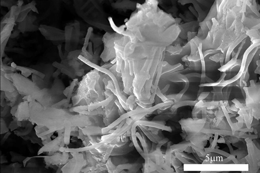
Figure S1: The SEM image C/SiOx-5%
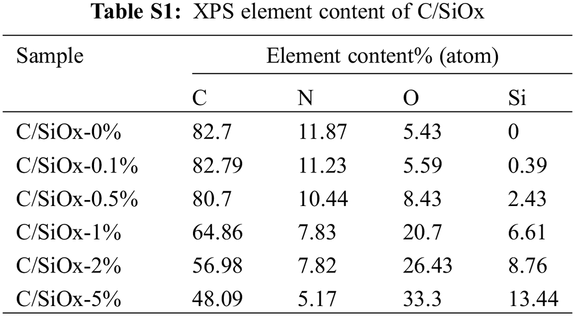
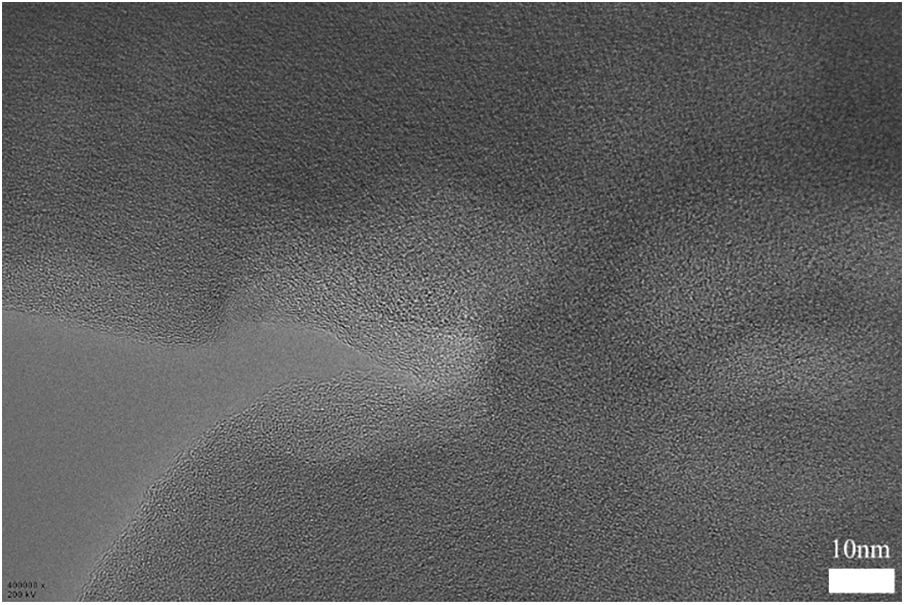
Figure S2: The TEM image of PAN-C on a 10-nanometer scale
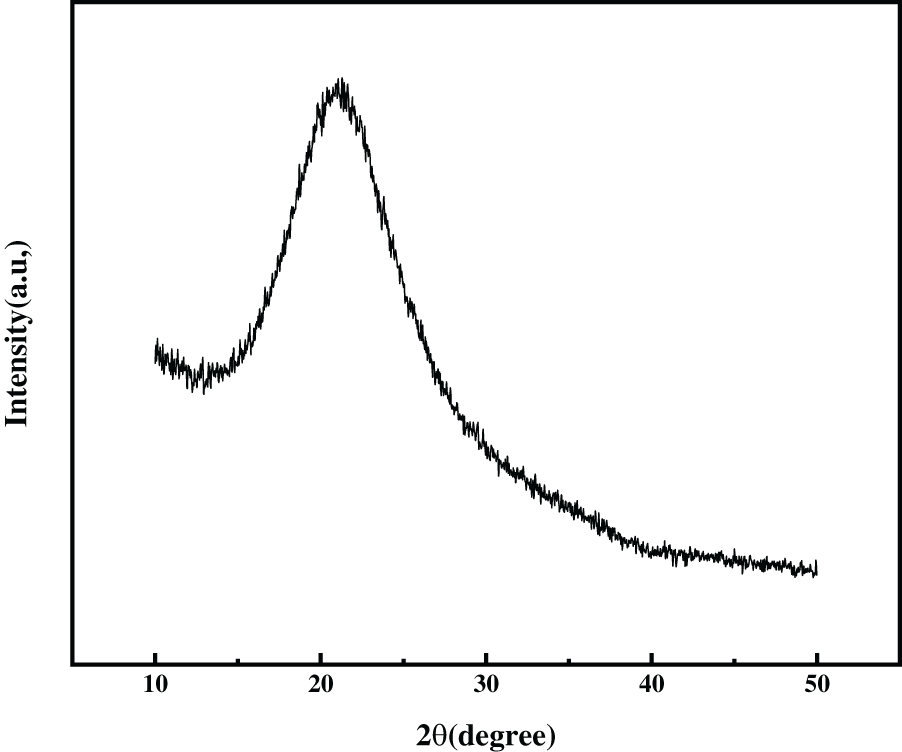
Figure S3: The XRD pattern of amorphous SiO2
Cite This Article
 Copyright © 2023 The Author(s). Published by Tech Science Press.
This work is licensed under a Creative Commons Attribution 4.0 International License , which permits unrestricted use, distribution, and reproduction in any medium, provided the original work is properly cited.
 Downloads
 Citation Tools