
 Submit a Paper
 Propose a Special lssue
 Open Access
ARTICLE

Theoretical Analysis on Deflection and Bearing Capacity of Prestressed Bamboo-Steel Composite Beams
1 School of Civil Engineering, Zhejiang Industry Polytechnic College, Shaoxing, 312000, China
2 School of Civil & Environmental Engineering and Geography Science, Ningbo University, Ningbo, 315211, China
3 College of Civil Engineering and Architecture, Qingdao Agricultural University, Qingdao, 266109, China
* Corresponding Author: Yushun Li. Email:
Journal of Renewable Materials 2024, 12(1), 149-166. https://doi.org/10.32604/jrm.2023.029445
Received 19 February 2023; Accepted 16 March 2023; Issue published 23 January 2024
 View Full Text
 Download PDF
Abstract
A theoretical analysis of upward deflection and midspan deflection of prestressed bamboo-steel composite beams is presented in this study. The deflection analysis considers the influences of interface slippage and shear deformation. Furthermore, the calculation model for flexural capacity is proposed considering the two stages of loading. The theoretical results are verified with 8 specimens considering different prestressed load levels, load schemes, and prestress schemes. The results indicate that the proposed theoretical analysis provides a feasible prediction of the deflection and bearing capacity of bamboo-steel composite beams. For deflection analysis, the method considering the slippage and shear deformation provides better accuracy. The theoretical method for bearing capacity matches well with the test results, and the relative errors in the serviceability limit state and ultimate limit state are 4.95% and 5.85%, respectively, which meet the accuracy requirements of the engineered application.Keywords
Bamboo is the most important plant resource in the world, characterized by a fast-growing rate, renewability, biodegradability, and carbon sequestration ability [1]. Bamboo scrimber is a new sustainable and renewable bamboo-based construction product, which is a breakthrough achieved by the bamboo processing industry [2,3]. Therefore, numerous bamboo materials [4,5], bamboo-based members [6–8], and structures [9,10] are developed and investigated.
Nevertheless, the flexural members made by bamboo scrimber had higher deflection compared with concrete and steel members [11–13]. In this case, the bamboo structure members strengthened by other materials such as steel reinforcement [14,15], steel plates [16,17], and FRP grids [18–20] were designed and investigated in recent years.
On the other hand, an I-shaped section is a type of highly efficient beam section, which can economically enhance the flexural stiffness and bearing capacity compared with a solid rectangular section [21]. Chen et al. [22] proposed composite I-beams made of timber and bamboo; the bearing capacity and stiffness of these beams increased by 44.8% and 23.4% on average compared with ordinary timber beams. Ghanbari-Ghazijahani et al. [23] investigated timber I-beams with different strengthening strategies, and the test results showed that the load-carrying capacity of strengthened beams could be increased by 70%.
Thin-walled cold-formed steel is widely used in modern structures with high strength and stiffness, while the steel members tend to buckle before achieving ultimate strength [24]. In this case, a new bamboo-steel composite beam is proposed [25,26]. The composite beams consist of bamboo scrimber plates and thin-walled cold-formed steel channels, which combine the best features of the two materials while avoiding the disadvantages.
Large-span structure is an important form of the modern structural system [27]. To expand the application scope of the bamboo-steel composite structure and make full use of the high strength of bamboo and steel, a novel prestressed bamboo-steel composite beam is proposed, which is composed of thin-walled steel channel and bamboo scrimber panels and strengthened by externally prestressed strands (Fig. 1). The deflection and bearing capacity of large-span beams are important design parameters for the application. Numerical simulation and theoretical analysis on the flexural rigidity and bearing capacity of the prestressed reinforced bamboo/timber beams have been conducted in many studies [28–30]. Tian et al. [31] proposed theoretical equations for predicting the flexural resistance of laminated bamboo lumber beams strengthened with prestressed embedded steel bars based on the observed strain and stress distributions. Lago et al. [32] conducted a semi-analytical iterative procedure for the solution of the geometrical nonlinear problem of unbonded post-tensioning to capture and predict the experimental behavior. These papers focus on the studies of prestressed bamboo/timber beams with numerical simulation and complex theoretical models, which provide good references for our study. In this study, a theoretical analysis of deflection and bearing capacity is proposed in this paper, and verification with 8 specimens considering different prestressed load levels, load schemes, and prestress schemes. The paper can offer a reference for the application of prestressed bamboo-steel composite beams.
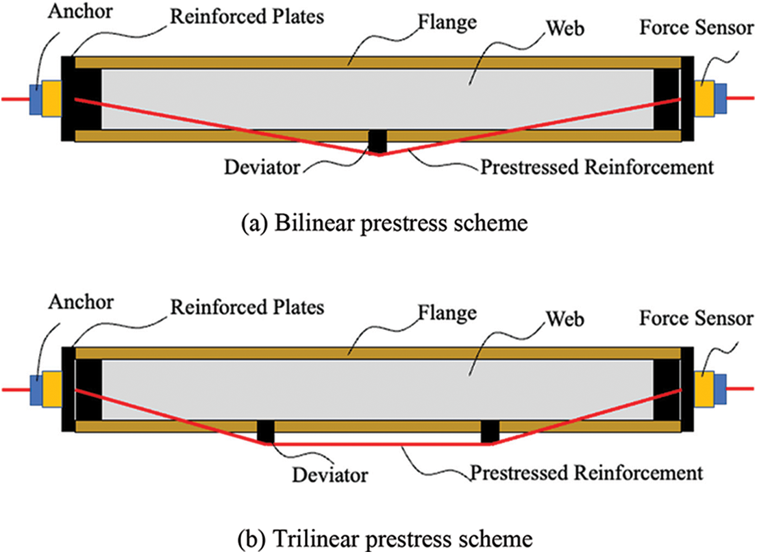
Figure 1: Diagram of prestressed bamboo-steel composite beam
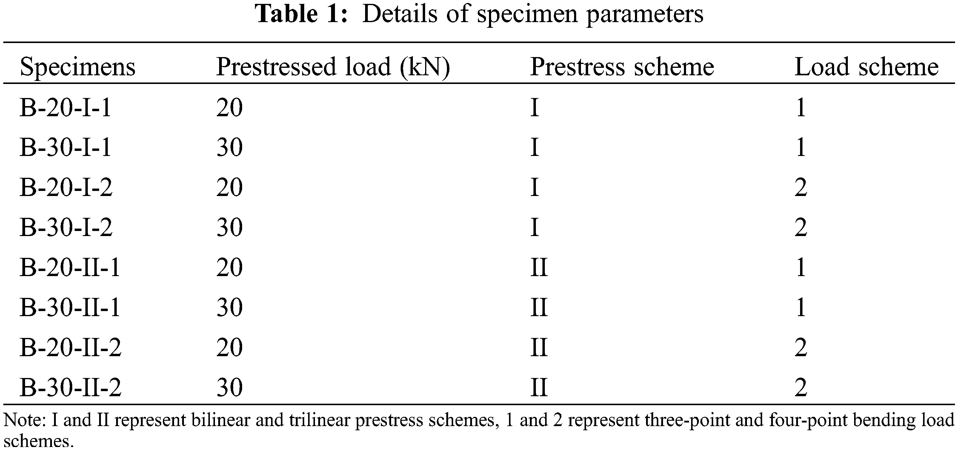
To analyze the bearing capacity and deflection of prestressed bamboo-steel composite beams, 8 I-shaped composite beams were prepared for the test. The specimens are shown in Fig. 2a. The specimens have the same section dimension (Fig. 2b). The length of specimens was 3800 mm, while the calculated span was 3500 mm. The main design parameters were prestressed load levels, prestress schemes, and load schemes. The detailed parameters of specimens are listed in Table 1.

Figure 2: Specimens of composite beams
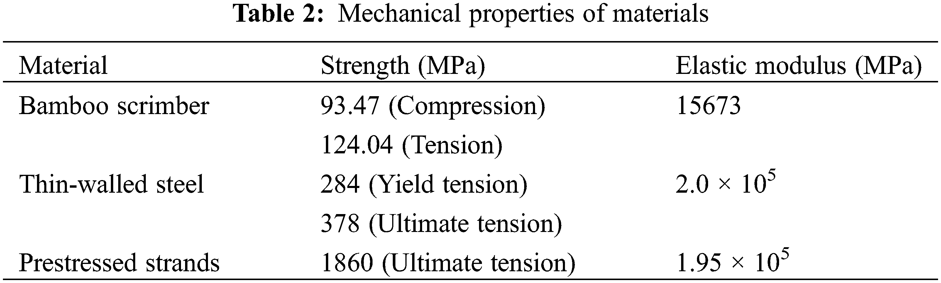
The bamboo-steel composite beam is made of cold-formed thin-walled steel and bamboo scrimber bonded by adhesive. The adhesive is Henkel EA3162A/B component epoxy adhesive, manufactured by LOCTITE. The prestressed strands are made of seven-strand wire, whose nominal diameter is 15.2 mm. The main mechanical properties of the three materials are shown in Table 2, in which the strength and elastic modulus of thin-walled steel and bamboo scrimber are measured according to standards [33] and [34], respectively. The mechanical properties of prestressed strands are provided by the manufacturer.
The fabrication of the specimens is as follows: first, the surfaces of the bamboo panel and steel channel were polished with polishers and cleaned with alcohol wipes (Fig. 3a). Then, the web surfaces of the steel channel and bamboo panel were evenly coated with adhesive. The steel channel and bamboo web were bonded together to manufacture the web skeleton of the composite beams. Ballasts and fixtures were employed to fix the web skeleton for seven days to ensure the quality of the interface between the bamboo and steel channel (Fig. 3b). Third, the bamboo flange and steel flange were bonded with the same treatments above (Fig. 3c). The finished specimens without prestressed strands are shown in Fig. 2a.

Figure 3: Specimens preparation
As shown in Fig. 4, two external prestressed strands are employed to apply prestress to bamboo-steel composite beams. The prestressing scheme can be divided into a bilinear prestress scheme and a trilinear prestress scheme according to different layouts of prestressed strands. The deviators are adopted to change the layouts of strands. The deviators were installed in the middle of the beams for the bilinear prestress scheme. The distance between the deviator and the adjacent support point is 1200 mm for the trilinear prestress scheme.
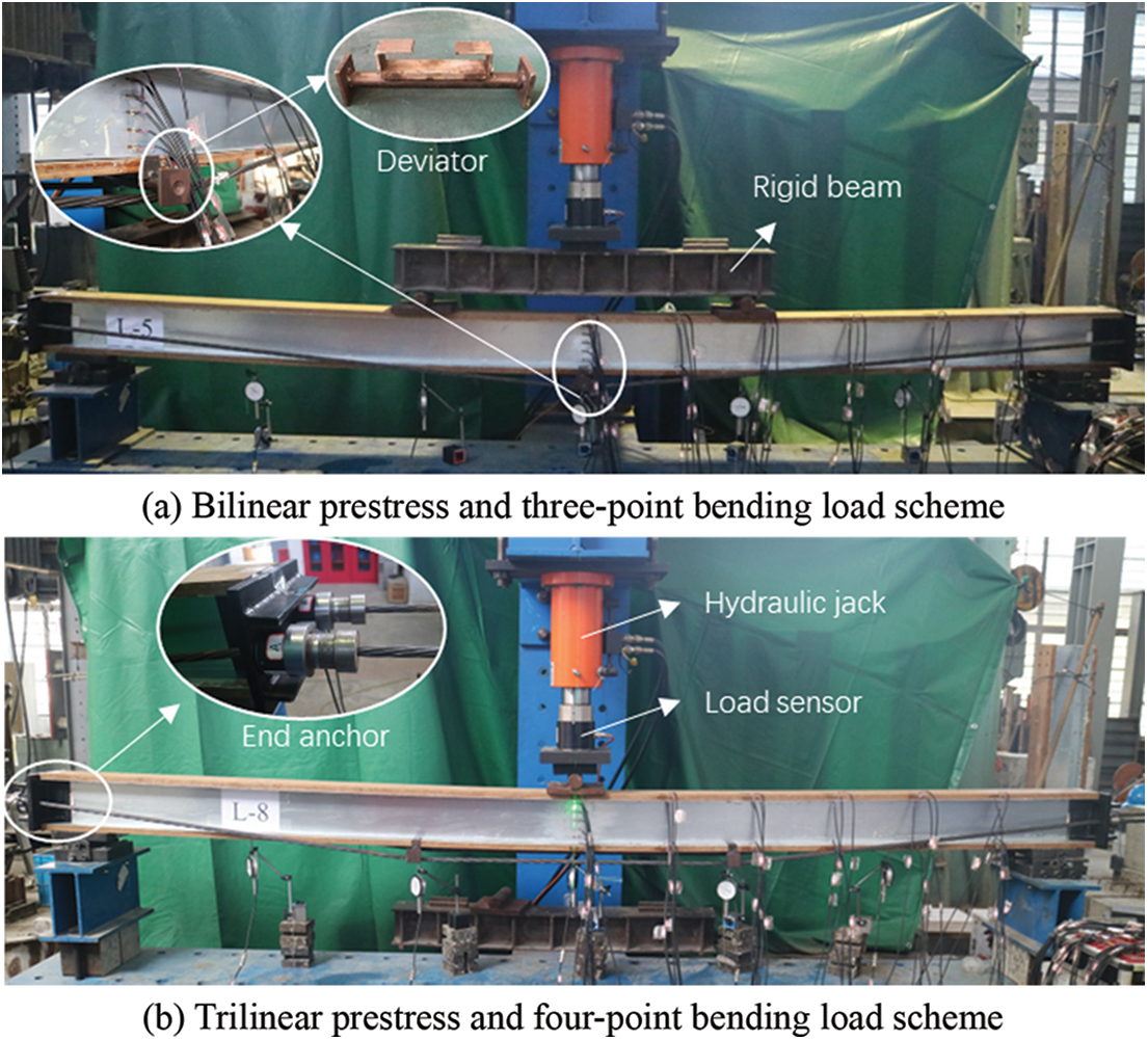
Figure 4: Prestress and load scheme
A universal reaction frame was adopted for the test, and the vertical load was applied through a hydraulic jack and measured by a load sensor. The load control strategy with the step of 5 kN was employed for loading. There are two schemes for vertical loading according to Fig. 4. For the three-point bending load scheme, and the vertical load is directly applied to the upper flange of the midspan section. While for the four-point bending load scheme, a rigid steel beam is used to achieve symmetric two-point loading, and the distance from the loading point to the adjacent support point is 1200 mm.
3 Deformation of Prestressed Bamboo-Steel Composite Beam
3.1 Additional Deflection Caused by Interface Slippage
Previous studies about the flexural behavior of bamboo-steel composite beams have indicated that slight slippage occurred between bamboo and steel [35]. The slippage has a certain influence on the deformation of the composite beams. The additional deflection caused by slippage should not be ignored [36].
The calculation method of additional deflection has been proposed and matches well with the test results according to the reference [37]. The formula can be expressed as follows:
where Δfs1 and Δfs2 are the additional deflections caused by one-point concentrated load and two-point symmetric load, respectively. F is the total load applied to the beam, L is the calculated span of beams, b is the distance between the two symmetric load points, h is the height of the beam section, K is the slip stiffness of interface among the unit length, Ab is the sectional area of bamboo, hf and hw are the height of sectional flange and web, respectively. E and I are the elastic modulus and section inertia moment, respectively, and subscripts b and s represent bamboo and steel.
3.2 Additional Deflection Caused by Shear Deformation
The flexural behaviors of composite beams will be determined by the combined effects of bending moment and shear force [38,39]. The additional deflection caused by shear deformation should be considered when calculating the deformation of composite beams. According to the principle of virtual force in structural mechanics, the deflection deformation caused by shear force can be calculated and solved by the graph multiplication method, as shown in Fig. 5. The additional deflection Δfv1 caused by shear deformation under the concentrated load and Δfv2 caused by shear deformation under the two-point symmetric load can be calculated as follows:
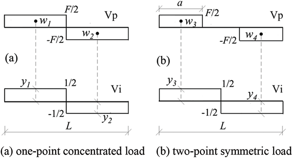
Figure 5: Calculation diagram of graph multiplication method
where k is the uniformity coefficient of shear stress distribution, which is only related to the shape of the section, and the specific value can be obtained from Eq. (2.3). G and A are the shear modulus and section area, respectively, and a is the distance between the load point and the adjacent support point.
3.3 Upward Deflection Caused by Prestress
The application of prestressed reinforcement may cause an upward deflection for the beam. According to the equivalent theory of statics, the effect of prestressed reinforcement can be equivalent to upward forces acting on the deviators. Therefore, the bilinear prestress scheme can be seen as a concentrated upward force acting on the midspan of the beam, and the trilinear prestress scheme can be regarded as two symmetric upward forces acting upon the deviators (Fig. 6).
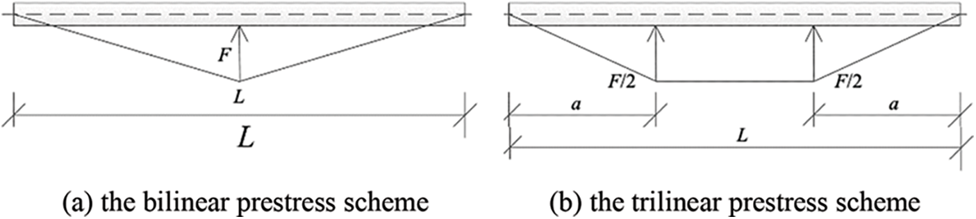
Figure 6: Equivalent load for prestressed reinforcement
Without considering the influence of additional deflection, the mid-span deflection of composite beams can be expressed according to the mechanics of materials as follows:
where y1 is the midspan deflection of the beam under the bilinear prestress scheme, y2 is the one under the trilinear prestress scheme.
Therefore, the midspan upward deflection r can be expressed as Eq. (4). The total midspan upward deflection R considering the slippage and shear deformation can be expressed as Eq. (5).
where i = 1 or 2, represents the bilinear prestress scheme or the trilinear prestress scheme, respectively.
According to the test overview above, the midspan deflection of the prestressed composite beam under the four conditions (i.e., the bilinear prestress and three-point bending scheme, the bilinear prestress and four-point bending load scheme, the trilinear prestress and three-point bending load scheme, the trilinear prestress and four-point bending load scheme) are discussed in this paper.
3.4.1 Bilinear Prestress Scheme
The deformation of composite beams under the external load will cause the stress increment of the prestressed reinforcements, in turn, the stress increment may offset the deformation of beams. Therefore, the final deflection of the prestressed beam is the interaction caused by external load and stress increment of prestressed reinforcements.
The load condition and deformation of beams under the bilinear prestress and three-point bending load scheme are shown in Fig. 7a. The midspan deflection x under the external load causes the stress increment Q of a single strand, and the stress increment causes the upward load increment ΔN, the specific expressions are as follows:
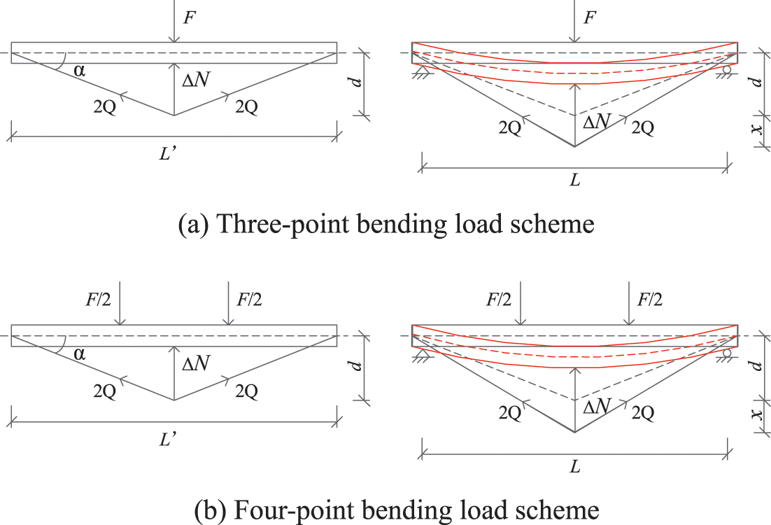
Figure 7: Deformation of bilinear prestress scheme
where l0 and l1 are the original length and final elongation length of prestressed reinforcement, respectively. L′ is the total length of the composite beam, d is the centroid distance between the beam and prestressed reinforcement, Ep and Ap are the elastic modulus and area of prestressed reinforcement, respectively.
According to the superposition principle and Eq. (3.1), the deflection x can be expressed:
Similarly, the deformations of beams under the bilinear prestress and four-point bending load scheme are shown in Fig. 7b. The stress increment Q and upward load ΔN can be calculated through Eqs. (6.1) and (7.1). The deflection caused by external load and upward prestress equivalent load can be calculated by Eqs. (3.1) and (3.2), respectively. The deflection can be calculated based on the superposition principle:
The deflection can be obtained by solving the equations about x, the midspan deflection f1j of prestressed beams under the bilinear prestress scheme considering slippage and shear deformation can be calculated as follows:
where j = 1 or 2, represents a three-point bending load or four-point bending load scheme, respectively. ΔN is the result of combined actions, which has considered the influence of slippage and shear deformation. While in Eq. (10), the external load F should still consider the influence of slippage and shear deformation.
3.4.2 Trilinear Prestress Scheme
The load condition and deformation of beams under the trilinear prestress and three-point bending load scheme are shown in Fig. 8a. The original length l0 and final elongation length l1 of the prestressed reinforcement can be obtained:

Figure 8: Deformation of trilinear prestress scheme
where a′ is the distance between the deviator and the adjacent support point, and b is the distance between the two deviators.
Substituting Eqs. (11.1) and (11.2) into Eqs. (6.1) and (7.1), the load increment ΔN caused by stress increment Q can be calculated as follows:
The midspan deflection x can be obtained based on the superposition principle:
Similarly, the deformations of beams under the trilinear prestress and four-point bending load scheme are shown in Fig. 8b. The midspan deflection x can be calculated as follows:
The deflection can be obtained by solving the equations about x, the midspan deflection f2j of prestressed beams under the trilinear prestress scheme considering slippage and shear deformation can be calculated as follows:
where, j = 1 or 2, represents a three-point bending load scheme or four-point bending load scheme, respectively.
4 Bearing Capacity of Prestressed Bamboo-Steel Composite Beams
4.1 Stress Increment of Prestressed Reinforcement
The prestressed bamboo-steel composite beams can be regarded as one-degree of statically indeterminate structures composed of external prestressed reinforcement and bamboo-steel composite beams. The stress increment of prestressed reinforcement can be solved by the force method in structural mechanics. To simplify the theoretical analyses, some basic assumptions are introduced:
(1) The composite beam sections conform to the plane section assumption.
(2) The deformation of the end anchorage device is neglected.
(3) The prestressed reinforcement is considered as an elastic body.
(4) The stress of the prestressed reinforcement is assumed to be equal along the length direction.
4.1.1 Bilinear Prestress Scheme
The basic diagram of the bilinear prestress and three-point bending load scheme for the force method is shown in Fig. 9a. The basic equation for the force method is expressed as follows:
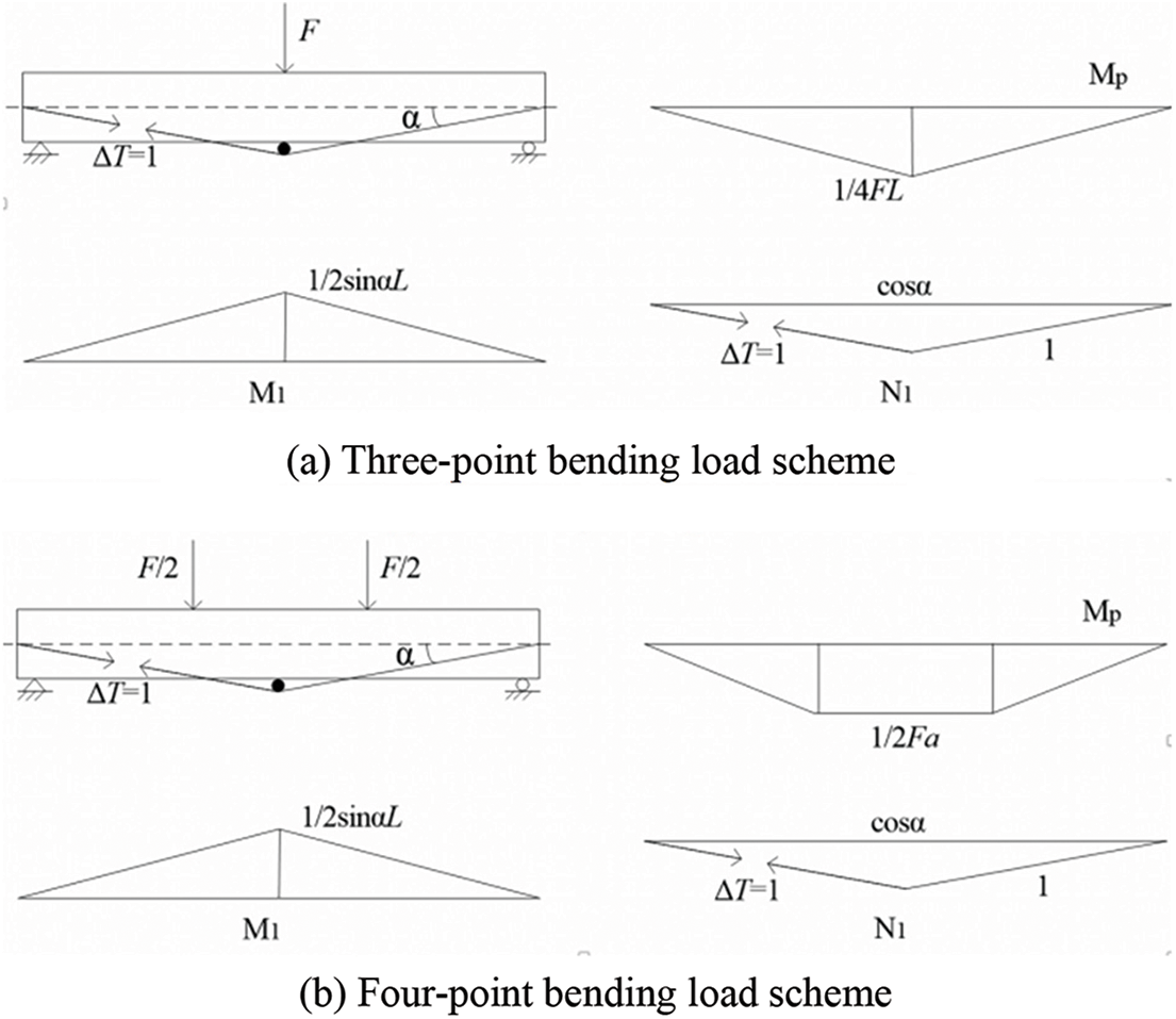
Figure 9: Basic diagram of bilinear prestress scheme
where ΔT is the stress increment of prestressed reinforcement, δ11 is the displacement caused by unit load, and Δ1p is the displacement caused by the external load. The δ11 and Δ1p can be calculated according to the virtual work principle.
where,
The basic diagram of the bilinear prestress and four-point bending load scheme is shown in Fig. 9b. The δ11 can be calculated according to Eq. (17.1), while Δ1p can be obtained as follows:
4.1.2 Trilinear Prestress Scheme
The basic diagram of the trilinear prestress and three-point bending load scheme for the force method is shown in Fig. 10a. The δ11 and Δ1p can be calculated as follows:
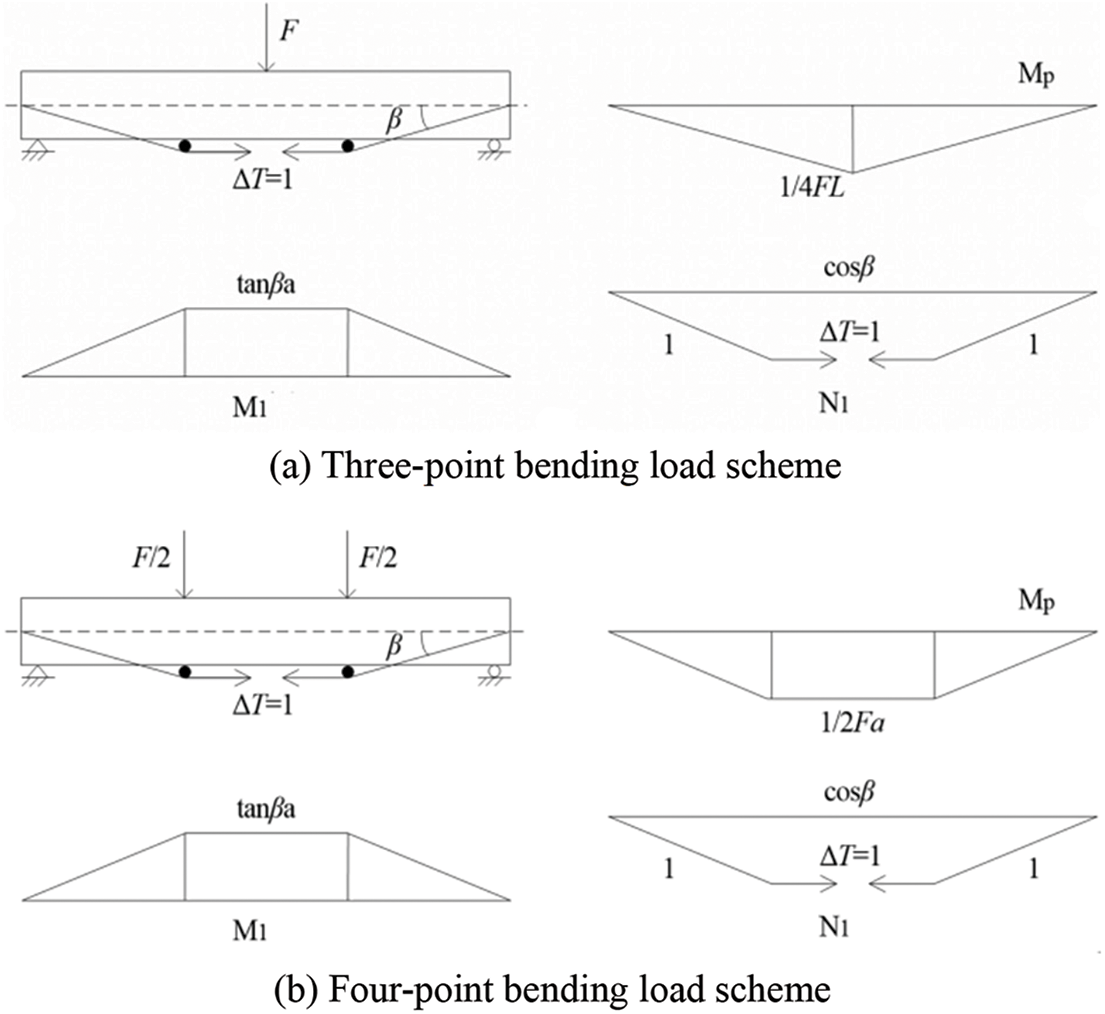
Figure 10: Basic diagram of trilinear prestress scheme
The basic diagram of the trilinear prestress and four-point bending scheme is shown in Fig. 10b. The δ11 can be calculated according to Eq. (19.1), while Δ1p can be obtained as follows:
Thus, the stress increment ΔT under the different prestress and load schemes can be obtained by substituting the corresponding δ11 and Δ1p into Eq. (16).
4.2 Flexural Load-Bearing Capacity
To analyze the flexural load-bearing capacity of the prestressed composite beams, the whole loading process can be divided into two stages. In the first stage, the deflection of beams changes from a precamber state to zero. In the second stage, the deflection of beams changes from zero to the positive ultimate limit state with the combined action of external load and prestressed reinforcement. Thus, the critical state is when the deflection of composite beams reaches zero.
4.2.1 Bearing Capacity in the First Stage
In the first stage, when the bearing capacity reaches the maximum, the deflection of the composite beams is zero, i.e., yp + ys = 0, where yp is the deflection of composite beams without prestressed reinforcement caused by the external load, ys is the upward deflection caused by prestress.
For the bilinear prestress and four-point bending load scheme, the yp and ys can be expressed as follows:
where F1 is the load bearing-capacity of the prestressed bamboo-steel composite beams in the first stage. Thus, the F1 for the bilinear prestress and four-point bending load scheme can be obtained:
Similarly, the bearing capacity for the other three schemes can be expressed:
For the bilinear prestress and three-point bending load scheme:
For the trilinear prestress and three-point bending load scheme:
For the trilinear prestress and four-point bending load scheme:
where ΔN is the total upward load increment caused by prestressed reinforcement, which can be calculated based on Eqs. (7.1) or (12.1) according to different prestressing schemes.
4.2.2 Bearing Capacity in the Second Stage
The ultimate bending moment Mu of the composite beam in the second stage can be calculated according to the superposition principle.
where Ms and Mb are the ultimate bending moment provided by steel channel and bamboo, respectively. Ws and Wb Are the elastic section modulus of steel and bamboo, respectively. fu is the ultimate stress of steel. Some references [25,35] indicated that the steel reached the plastic stage in the ultimate limit state, and the plastic ratio of steel γs (γs = 1.05) was introduced to consider the plastic behavior. σb is the stress of bamboo, which can be calculated: σb = εbEb. According to the reference, slight debonding could be observed during the bamboo-steel composite beam test, so the strength reduction facto γb (γb = 0.95) is introduced.
The ultimate bending moment M of prestressed composite beams also can be expressed according to the external load and prestressed reinforcement.
For the bilinear prestress and three-point bending load scheme:
For the bilinear prestress and four-point bending load scheme:
For the trilinear prestress and three-point bending load scheme:
For the trilinear prestress and four-point bending load scheme:
For the same specimens, the M above should be equal to Mu calculated according to Eq. (23.1). Therefore, the load-bearing capacity F2 in the second stage can be obtained. The total load-bearing capacity F of the prestressed composite beams can be calculated as follows:
5 Verification with Experiments
The theoretical and experimental results of upward deflection are shown in Table 3. The results show that the theoretical values match well with the experimental values except for specimen B-30-I-1, indicating the accuracy of the theoretical analysis. The theoretical method cannot predict the upward deflection of specimens B-30-I-1, which may attribute to the measuring error of B-30-I-1 in the prestressing process.
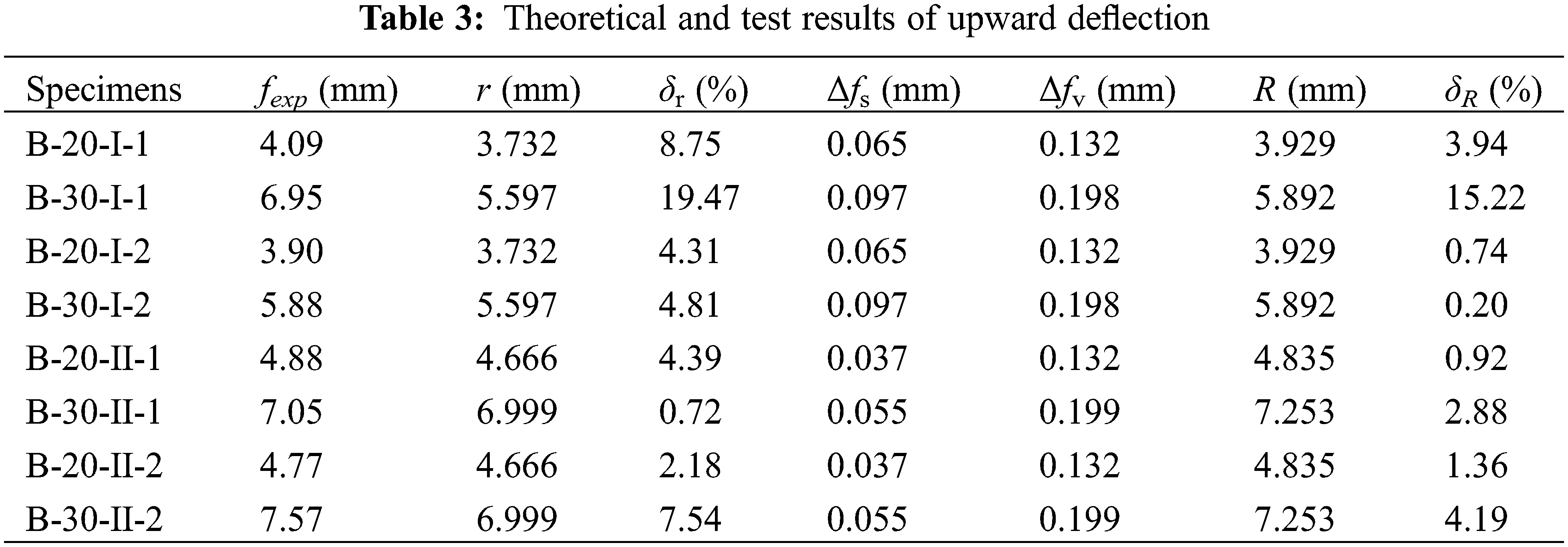
Table 3 lists the upward deflection r and relative error δr without considering the slippage and shear deformation, and the average relative error is 4.67%. The calculation method is simple, and the accuracy is adequate for the engineered application. Meanwhile, the theoretical upward deflection R considering the additional deflection is also listed in Table 3. The results show that the upward deflection R is closer to the test values, the relative error δR is less than 5%, and the average error is only 2.03%, indicating that slippage and shear deformation are key factors in improving the theoretical analysis accuracy.
5.1.2 Midspan Deflection in Serviceability Limit State
According to standard [40], the maximum allowable deflection at the serviceability limit state is l/250 (l is the calculated span), which is equal to 14 mm in this paper. The corresponding load is defined as a serviceable load.
Due to the step load control strategy adopted in the test, the measuring equipment cannot exactly record the allowable defection and serviceable load. Therefore, the deflection closed to 14 mm, and the corresponding load (P) was selected for comparison.
Fig. 11 compares the midspan deflection curves between the test and calculated during the loading process. The comparisons indicate that the theoretical method provides a feasible prediction of the deflection increase in the experiment.
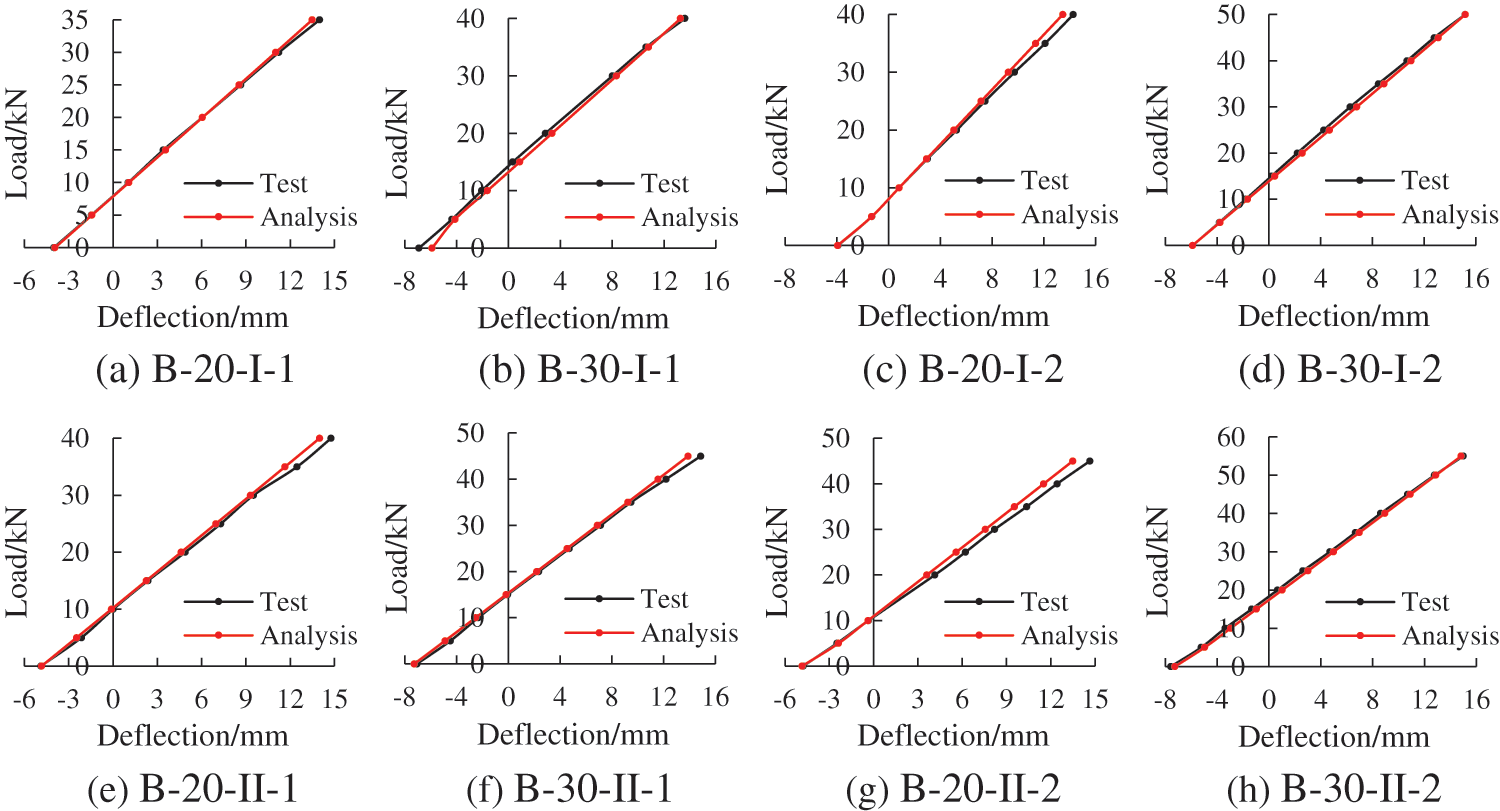
Figure 11: Comparisons of midspan deflections in serviceability limit state
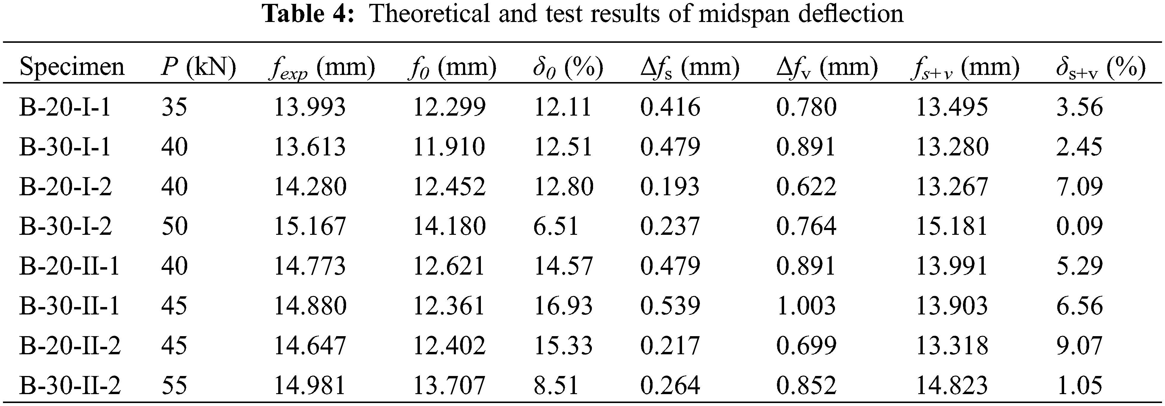
Table 4 lists the theoretical and test results of midspan deflection in the serviceability limit state. It is noticed that the theoretical method (f0) without considering the slippage and shear deformation causes larger errors; the average relative error is 12.41%. While for calculation results fs+v considering the slippage and shear deformation, the accuracy is significantly improved, and the relative error δs+v is no more than 10%, the average errors reduce from 12.41% to 4.39%. It is shown that the theoretical calculation method based on slippage and shear deformation has higher accuracy, which can support the application of prestressed bamboo-steel composite beams.
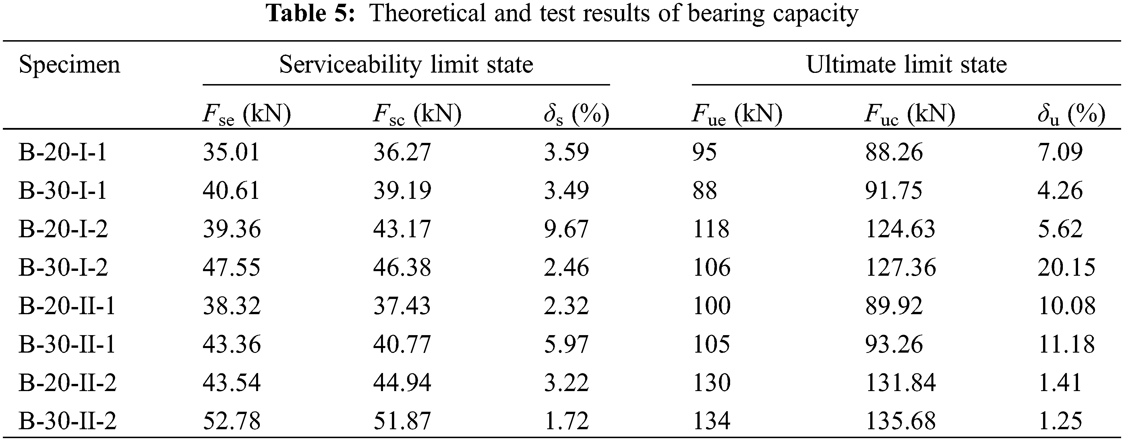
The test results and calculation results of bearing capacity are listed in Table 5. The bearing capacity of composite beams in the serviceability limit state and ultimate limit state are calculated according to the theoretical analysis in Section 4. It is noticed that the calculation values Fsc in the serviceability limit state are in good agreement with the test value Fse. The relative error δs is no more than 10%, and the average error is 4.05%. While in the ultimate limit state, the theoretical method could also predict the test results except for specimen B-30-I-2, and the average relative error δu is 5.84%. For specimen B-30-I-2, due to the material defects, manufacture technology, and so on, the specimen was damaged in advance, resulting in a small bearing capacity and a considerable error.
In this study, the theoretical analysis of deflection and bearing capacity of bamboo-steel composite beams is proposed and verified with experiment. The main results and findings are concluded as follows:
(1) The theoretical analysis of upward deflection is built based on the unit load method. The verification result indicates that the theoretical method considering slippage and shear deformation can improve the accuracy; the average errors reduce from 4.67% to 2.03%.
(2) A method is proposed to calculate the midspan deflection of composite beams. The comparisons indicate that the theoretical method provides a feasible prediction of the deflection in the experiment.
(3) The stress increment of prestressed reinforcement was established based on the force method. Then, a practical method is proposed to analyze the bearing capacity of the composite beams. The verification results show that the relative error of the proposed method is 4.05% and 5.85% for the serviceability limit state and ultimate limit state, which meet the accuracy requirement of the engineered application.
Funding Statement: This work was supported by the National Natural Science Foundation of China (51978345, 52278264).
Conflicts of Interest: The authors declare that they have no conflicts of interest to report regarding the present study.
References
1. Ji, S., Mou, Q., Yuan, G., Ren, H., Li, X. (2023). Dowel–bearing behavior of bamboo scrimber for bolted–type joint. Industrial Crops and Products, 193, 116178. https://doi.org/10.1016/j.indcrop.2022.116178 [Google Scholar] [CrossRef]
2. Dauletbek, A., Li, H., Lorenzo, R., Corbi, I., Corbi, O. et al. (2022). A review of basic mechanical behavior of laminated bamboo lumber. Journal of Renewable Materials, 10(2), 273–300. https://doi.org/10.32604/jrm.2022.017805 [Google Scholar] [CrossRef]
3. Sun, X., He, M., Li, Z. (2020). Novel engineered wood and bamboo composites for structural applications: State-of-art of manufacturing technology and mechanical performance evaluation. Construction and Building Materials, 249(6780), 118751. https://doi.org/10.1016/j.conbuildmat.2020.118751 [Google Scholar] [CrossRef]
4. Sharma, B., Gatóo, A., Bock, M., Ramage, M. (2015). Engineered bamboo for structural applications. Construction and Building Materials, 81(2), 66–73. https://doi.org/10.1016/j.conbuildmat.2015.01.077 [Google Scholar] [CrossRef]
5. Wu, M., Mei, L., Guo, N., Ren, J., Zhang, Y. et al. (2022). Mechanical properties and failure mechanisms of engineering bamboo scrimber. Construction and Building Materials, 344, 128082. https://doi.org/10.1016/j.conbuildmat.2022.128082 [Google Scholar] [CrossRef]
6. Li, H., Su, J., Zhang, Q., Deeks, A. J., Hui, D. (2015). Mechanical performance of laminated bamboo column under axial compression. Composites Part B: Engineering, 79(9), 374–382. https://doi.org/10.1016/j.compositesb.2015.04.027 [Google Scholar] [CrossRef]
7. Wang, J. S., Demartino, C., Xiao, Y., Li, Y. Y. (2018). Thermal insulation performance of bamboo- and wood-based shear walls in light-frame buildings. Energy and Buildings, 168(4), 167–179. https://doi.org/10.1016/j.enbuild.2018.03.017 [Google Scholar] [CrossRef]
8. Chen, G., Yu, Y., Li, X., He, B. (2019). Mechanical behavior of laminated bamboo lumber for structural application: An experimental investigation. European Journal of Wood and Wood Products, 78(1), 53–63. https://doi.org/10.1007/s00107-019-01486-9 [Google Scholar] [CrossRef]
9. Sassu, M., de Falco, A., Giresini, L., Puppio, M. L. (2016). Structural solutions for low-cost bamboo frames: Experimental tests and constructive assessments. Materials, 9(5), 346. https://doi.org/10.3390/ma9050346 [Google Scholar] [PubMed] [CrossRef]
10. Lv, Q., Ding, Y., Liu, Y. (2019). Concept and development of a steel-bamboo SI (skeleton-infill) system: Experimental and theoretical analysis. Journal of Wood Science, 65(1), 51. https://doi.org/10.1186/s10086-019-1830-4 [Google Scholar] [CrossRef]
11. Huang, D., Zhou, A., Bian, Y. (2013). Experimental and analytical study on the nonlinear bending of parallel strand bamboo beams. Construction and Building Materials, 44, 585–592. https://doi.org/10.1016/j.conbuildmat.2013.03.050 [Google Scholar] [CrossRef]
12. Sewar, Y. Y., Zhang, Z., Meng, X., Wahan, M. Y., Qi, H. et al. (2022). Mechanical properties and constitutive relationship of the high-durable parallel strand bamboo. Journal of Renewable Materials, 10(1), 219–235. https://doi.org/10.32604/jrm.2021.016013 [Google Scholar] [CrossRef]
13. Sinha, A., Way, D., Mlasko, S. (2014). Structural performance of glued laminated bamboo beams. Journal of Structural Engineering, 140(1), 04013021. https://doi.org/10.1061/(ASCE)ST.1943-541X.0000807 [Google Scholar] [CrossRef]
14. Zhao, K., Wei, Y., Yan, S., Chen, S., Dong, F. (2021). Experimental and analytical investigations on flexural behavior of bamboo beams strengthened with steel bars. Advances in Structural Engineering, 24(14), 3338–3356. https://doi.org/10.1177/13694332211026230 [Google Scholar] [CrossRef]
15. Luo, X., Ren, H., Zhong, Y. (2020). Experimental and theoretical study on bonding properties between steel bar and bamboo scrimber. Journal of Renewable Materials, 8(7), 773–787. https://doi.org/10.32604/jrm.2020.09414 [Google Scholar] [CrossRef]
16. Wang, Z., Wei, Y., Li, N., Zhao, K., Ding, M. (2020). Flexural behavior of bamboo-concrete composite beams with perforated steel plate connections. Journal of Wood Science, 66(1), 4. https://doi.org/10.1186/s10086-020-1854-9 [Google Scholar] [CrossRef]
17. Leng, Y., Xu, Q., Harries, K. A., Chen, L., Liu, K. et al. (2020). Experimental study on mechanical properties of laminated bamboo beam-to-column connections. Engineering Structures, 210, 110305. https://doi.org/10.1016/j.engstruct.2020.110305 [Google Scholar] [CrossRef]
18. Li, Y., Xie, Y., Tsai, M. (2009). Enhancement of the flexural performance of retrofitted wood beams using CFRP composite sheets. Construction and Building Materials, 23(1), 411–422. https://doi.org/10.1016/j.conbuildmat.2007.11.005 [Google Scholar] [CrossRef]
19. Nadir, Y., Nagarajan, P., Ameen, M., Arif, M. M. (2016). Flexural stiffness and strength enhancement of horizontally glued laminated wood beams with GFRP and CFRP composite sheets. Construction and Building Materials, 112(10), 547–555. https://doi.org/10.1016/j.conbuildmat.2016.02.133 [Google Scholar] [CrossRef]
20. Lv, Q., Wang, W., Liu, Y. (2019). Flexural performance of cross-laminated bamboo (CLB) slabs and CFRP grid composite CLB slabs. Advances in Civil Engineering, 2019, 6980782. https://doi.org/10.1155/2019/6980782 [Google Scholar] [CrossRef]
21. Yang, R., Hong, C., Zhang, X., Yuan, Q., Sun, Y. (2020). Experimental research on structural behaviors of glulam I-beam with a special-shaped section. Journal of Renewable Materials, 8(2), 113–132. https://doi.org/10.32604/jrm.2020.08190 [Google Scholar] [CrossRef]
22. Chen, S., Wei, Y., Zhao, K., Dong, F., Huang, L. (2022). Experimental investigation on the flexural behavior of laminated bamboo-timber I-beams. Journal of Building Engineering, 46, 103651. https://doi.org/10.1016/j.jobe.2021.103651 [Google Scholar] [CrossRef]
23. Ghanbari-Ghazijahani, T., Russo, T., Valipour, H. R. (2020). Lightweight timber I-beams reinforced by composite materials. Composite Structures, 233(6), 111579. https://doi.org/10.1016/j.compstruct.2019.111579 [Google Scholar] [CrossRef]
24. Han, K., Lee, C. (2016). Elastic flange local buckling of I-shaped beams considering effect of web restraint. Thin-Walled Structures, 105(12), 101–111. https://doi.org/10.1016/j.tws.2016.04.001 [Google Scholar] [CrossRef]
25. Li, Y., Shan, W., Shen, H., Zhang, Z., Liu, J. (2015). Bending resistance of I-section bamboo-steel composite beams utilizing adhesive bonding. Thin-Walled Structures, 89(5), 17–24. https://doi.org/10.1016/j.tws.2014.12.007 [Google Scholar] [CrossRef]
26. Zhang, J., Zhang, Z., Tong, K., Wang, J., Li, Y. (2020). Bond performance of adhesively bonding interface of steel-bamboo composite structure. Journal of Renewable Materials, 8(6), 687–702. https://doi.org/10.32604/jrm.2020.09513 [Google Scholar] [CrossRef]
27. Munch-Andersen, J., Dietsch, P. (2011). Robustness of large-span timber roof structures—Two examples. Engineering Structures, 33(11), 3113–3117. https://doi.org/10.1016/j.engstruct.2011.03.015 [Google Scholar] [CrossRef]
28. Wei, Y., Yan, S., Zhao, K., Dong, F., Li, G. (2020). Experimental and theoretical investigation of steel-reinforced bamboo scrimber beams. Engineering Structures, 223, 111179. https://doi.org/10.1016/j.engstruct.2020.111179 [Google Scholar] [CrossRef]
29. Zhang, J., Shen, H., Qiu, R., Xu, Q., Gao, S. (2020). Short-term flexural behavior of prestressed glulam beams reinforced with curved tendons. Journal of Structural Engineering, 146(6), 04020086. https://doi.org/10.1061/(ASCE)ST.1943-541X.0002625 [Google Scholar] [CrossRef]
30. Yang, H., Liu, W., Lu, W., Zhu, S., Geng, Q. (2016). Flexural behavior of FRP and steel reinforced glulam beams: Experimental and theoretical evaluation. Construction and Building Materials, 106(10), 550–563. https://doi.org/10.1016/j.conbuildmat.2015.12.135 [Google Scholar] [CrossRef]
31. Tian, Y., Li, H., Chen, B., Lorenzo, R., Ashraf, M. (2023). Experimental and theoretical investigation of prestressed-steel-reinforced laminated bamboo lumber beams. Structures, 47(1), 434–448. https://doi.org/10.1016/j.istruc.2022.10.135 [Google Scholar] [CrossRef]
32. Lago, B. D., Dibenedetto, C., Palermo, A., Pampanin, S., Giorgini, S. et al. (2017). Structural behavior of longitudinally posttensioned timber beams under serviceability gravity loading. Journal of Structural Engineering, 143(8), 04017071. https://doi.org/10.1061/(ASCE)ST.1943-541X.0001800 [Google Scholar] [CrossRef]
33. China National Standard (2021). Metallic materials—Tensile testing—Part 1: Method of test at room temperature (GB/T 228.1-2021). China: Standards Press of China. [Google Scholar]
34. China National Standard (2022). Test methods of evaluating the properties of wood-based panels and surface decorated wood-based panels (GB/T 17657-2022). China: Standards Press of China. [Google Scholar]
35. Shan, Q., Zhang, J., Tong, K., Li, Y. (2020). Study on flexural behaviour of box section bamboo-steel composite beams. Advances in Civil Engineering, 2020(4), 8878776. https://doi.org/10.1155/2020/8878776 [Google Scholar] [CrossRef]
36. Duan, Y., Zhang, J., Tong, K., Wu, P., Li, Y. (2021). The effect of interfacial slip on the flexural behavior of steel-bamboo composite beams. Structures, 32(1), 2060–2072. https://doi.org/10.1016/j.istruc.2021.04.019 [Google Scholar] [CrossRef]
37. Li, Y., Zhang, J., Tong, K., Guo, J., Wu, P. (2018). Study on interface slip and deformation of bamboo-steel composite beams. Engineering Mechanics, 35(7), 150–158+166. https://doi.org/10.6052/j.issn.1000-4750.2017.03.0215 [Google Scholar] [CrossRef]
38. Gordaninejad, F., Ghazavi, A. (1989). Effect of shear deformation on bending of laminated composite beams. Journal of Pressure Vessel Technology, 111(2), 159–164. https://doi.org/10.1115/1.3265652 [Google Scholar] [CrossRef]
39. Laudiero, F., Savoia, M. (1990). Shear strain effects in flexure and torsion of thin-walled beams with open or closed cross-section. Thin-Walled Structures, 10(2), 87–119. https://doi.org/10.1016/0263-8231(90)90058-7 [Google Scholar] [CrossRef]
40. China National Standard (2017). Standard for design of timber structures (GB 50005-2017). China: China Architecture & Building Press. [Google Scholar]
Cite This Article
 Copyright © 2024 The Author(s). Published by Tech Science Press.
This work is licensed under a Creative Commons Attribution 4.0 International License , which permits unrestricted use, distribution, and reproduction in any medium, provided the original work is properly cited.
 Downloads
 Citation Tools