
 Submit a Paper
 Propose a Special lssue
 Open Access
ARTICLE
Weak Fault Detection of Rotor Winding Inter-Turn Short Circuit in Excitation System Based on Residual Interval Observer
1 Zhejiang Zheneng Jiahua Power Generation Co., Ltd., Hangzhou, 314201, China
2 Zhejiang Zheneng Technology Research Institute Co., Ltd., Hangzhou, 310000, China
3 Zhejiang Key Laboratory of High Efficiency, Energy Saving and Pollutant Control Technology for Thermal Power Generation, Hangzhou, 310000, China
4 Shanghai Jiaotong University, Shanghai, 200240, China
* Corresponding Author: Xinqi Chen. Email:
Structural Durability & Health Monitoring 2023, 17(4), 337-351. https://doi.org/10.32604/sdhm.2022.023583
Received 04 May 2022; Accepted 18 July 2022; Issue published 02 August 2023
 View Full Text
 Download PDF
Abstract
Aiming at the fact that the rotor winding inter-turn weak faults can hardly be detected due to the strong electromagnetic coupling effect in the excitation system, an interval observer based on current residual is designed. Firstly, the mechanism of the inter-turn short circuit of the rotor winding in the excitation system is modeled under the premise of stable working conditions, and electromagnetic decoupling and system simplification are carried out through Park Transform. An interval observer is designed based on the current residual in the two-phase coordinate system, and the sensitive and stable conditions of the observer is preset. The fault diagnosis process based on the interval observer is formulated, and the observer gain matrix is convexly optimized by linear matrix inequality. The numerical simulation and experimental results show that the inter-turn short circuit weak fault is hardly detected directly through the current signal, but the fault is quickly and accurately diagnosed through the residual internal observer. Compared with the traditional fault diagnosis method based on excitation current, the diagnosis speed and accuracy are greatly improved, and the probability of misdiagnosis also decreases. This method provides a theoretical basis for weak fault identification of excitation systems, and is of great significance for the operation and maintenance of excitation systems.Keywords
In recent years, with the continuous promotion of infrastructure and urbanization in major emerging economies, the requirements for the working stability of the power supply system under the condition of high-power and long-distance transmission have gradually increased [1–3]. With the expanding development trend of the scale of generator units, how to ensure the reliable operation of the system has become a key problem in the current field. As an important part of the generator set, the excitation system often works in an alternating magnetic and electric fields [4–7]. When the excitation system fails, it directly affects the service performance of the generator set and even causes serious safety accidents [8,9]. However, the faults are not obvious at the early stage due to the complex structure of the excitation system, and it is difficult to detect the faults based on a fixed threshold [10–12]. The under-maintenance of the excitation system seriously affects the efficiency of the excitation system and causes great difficulties for subsequent maintenance [13–15]. Weak faults detection at the initial stages has attracted extensive attention, and is obviously of great significance.
Rotor winding inter-turn short circuit is a common fault form in excitation system, and is widely identified through the current signal [16–18]. Forstner et al. [19] proposed a fault-tolerant model for torque control strategy in a three-phase permanent magnet synchronous motor with an inter-turn winding short circuit, and identified the parameters of the inter-turn winding short circuit by a model-based method. Yang et al. [20] established an analysis on the physical parameters of the motor based on the mathematical model of inter-turn short circuit fault, and proposed a parameter estimation method based on improved trust region for the fault detection. Sarkar et al. [21] used the principal component analysis method to extract the characteristics of three-phase current signals, recorded the variation range of principal components, and obtained better inter-turn short circuit fault diagnosis accuracy. Faiz et al. [22] derived a rotor inter-turn short circuit fault model of induction motor, and addressed the impacts of the fault on the signals of the machine including rotor current, stator current, and developed torque. Besides the model-driven methods, deep learning methods were also applied to settle the problems [23,24]. Barron et al. [25] presented a multilayer neural network to reproduce the current signatures associated with inter-turn short circuit fault conditions. The above methods have high prediction accuracy and fast speed, but the thresholds of the high-precision methods are close to the normal signals, and the fault detection is easily affected by the current fluctuation caused by disturbance. Therefore, it is necessary to propose a fault detection method with stronger robustness and higher accuracy to improve the weak fault detection performance considering the current disturbance.
In recent years, the state observer has been widely used in the field of fault diagnosis due to the advantages of high precision and high robustness [26–29]. Zhang et al. [30] proposed an interval observer filtering-based fault diagnosis method for linear discrete-time systems with dual uncertainties. Chen et al. [31] presented a current observer-based online open-switch fault diagnosis method for the voltage-source inverters, which proved to be of high reliability and enhanced the post-fault maintenance efficiency of inverters. Venkateswaran et al. [32] discussed the solution for designing functional observers for fault diagnosis in nonlinear systems in the presence of noises. It is implied that the state observer has high accuracy in weak fault detection, and the application of state observer in conditions of electric-magnetic coupling system such as excitation systems needs to be verified [33,34].
In this paper, a residual interval observer is proposed to transfer the state discrimination basis from the traditional state domain to the residual domain, so that the state signal is more sensitive to fault occurrence and the fault state discrimination is more reliable. Then the advantages of the residual interval observer is discussed from the aspect of accuracy and detection time. Aiming at the coupling characteristic of the excitation system, the electromagnetic decoupling is carried out using Park transform. The model is built in Section 2, and case studies are presented in Section 3. Experiments are conducted to verify the effectiveness and detection performance of the proposed method in Section 4, and conclusions are drawn at last.
2 Rotor Winding Inter Turn Short Circuit Fault Model
2.1 Rotor Winding Circuit Model
The excitation system consists of the rotor and stator, and the excitation process between the rotor and stator is shown in Fig. 1.
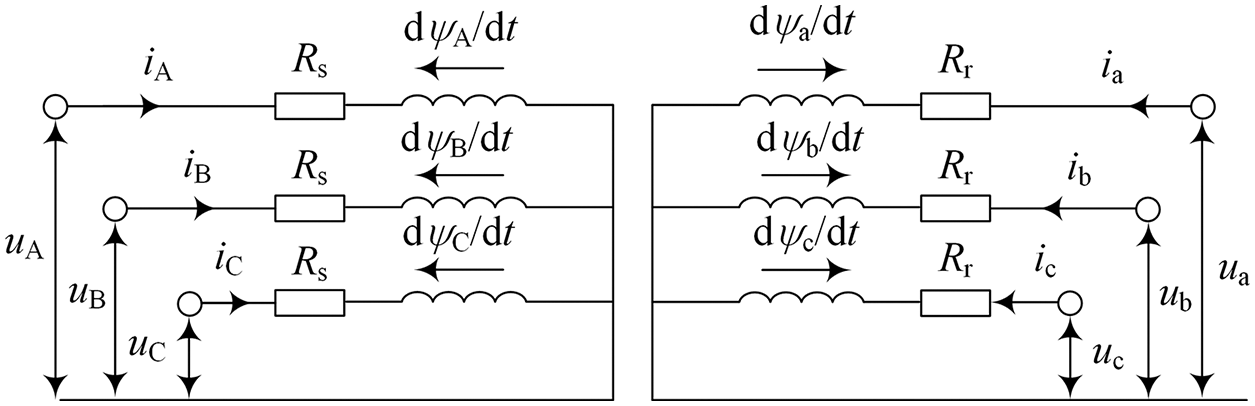
Figure 1: Rotor stator excitation process
In Fig. 1, uA, iA and ψA are voltages, currents and magnetic potentials at the A-terminal of the stator, uB, iB and ψB are voltages, currents and magnetic potentials at the B-terminal of the stator, uC, iC and ψC are voltages, currents and magnetic potentials at C-terminal of the stator. ua, ia and ψa are voltages, currents and magnetic potentials at the a-terminal of the rotor, ub, ib, ψb are the voltages, currents and magnetic potentials at the b-terminal of the rotor, uc, ic, ψc are the voltages, currents and magnetic potentials at the c-terminal of the rotor. Rs is the stator resistance, and Rr is the rotor resistance. The current and magnetic potential changes caused by the other external interference are ignored, and the stator and rotor voltages in the excitation system can be expressed as
When a short-circuit fault occurs in the excitation system, the excitation magnetic potential changes, the excitation current increases, and the loss in the system increases with the local temperature at the short-circuit point. The fault can be regarded as adding a short circuit in the system, as shown in Fig. 2.
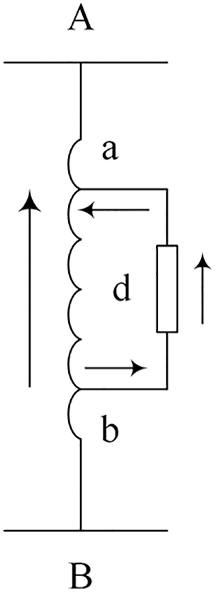
Figure 2: Short circuit of rotor winding
Here the short circuit is set as d, then another fault circuit equation needs to be added, and the matrix increases by one order, which can be expressed as
where μ is the short circuit coefficient. It can be seen that there are many parameters in the current coordinate system, and there exists electromagnetic coupling, so it is difficult to identify the weak faults. Here the Park Transform is used to transfer the parameters in the current coordinate system to dq two-phase coordinate system:
where id, iq show d-axis current and q-axis current, respectively, and θ is the angle between d-axis and a axis. Electromagnetic coupling can be eliminated through park transform, which is more suitable for fault diagnosis. The rotor winding state equation can be transformed into the following linear system:
where x(t) is status of the system, y(t) is system output, δ(t) is outer disturbance of the system, f(t) is fault signal of the system, A, C, D and F are the matrix coefficients of the system, respectively.
2.2 Residual Interval Observer Design
To improve the performance of weak fault detection, a residual interval observer is designed to distinguish the fault by generating residuals.
x(t) represents the state signal of the system, and the upper bound function and lower bound function in the observer can be expressed as
The upper and lower bound functions in the observer are constructed as
where C+ = max{0,C}, C− = C+−C; D+ = max{0, D}, D− = D+−D. L is Matrix gain, and W is relaxation matrix.
where
The influence of electromagnetic interference on the observer can be measured by l1 performance and H∞ performance. The l1 performance and H∞ performance indexes are shown in the following formula:
where the interference d is a bounded function,
The observer needs to have certain disturbance robustness to reduce the influence of external disturbance. The robustness of the observer is defined by Lyapunov function, as shown in the following formula:
where ed is the systematic error when f(t) = 0, if there are parameters
Then the designed observer can be considered to be robust. In Eq. (13), there is
Therefore, Eq. (13) is equivalent to the existence of matrix M, meeting that
Similarly, Eq. (14) is equivalent to the existence of matrix N, meeting that
When there is no fault in the system, f(t) = 0, so the observer should meet the following inequality constraints:
To improve the diagnostic sensitivity of the observer, the Lyapunov function shown in the following formula is constructed:
where P2 > 0, ef is the systematic error when δ(t) = 0. If there is a parameter matrix γ > 0, slack matrix W> 0 so that the matrix satisfies the following inequality:
It can be considered that the system is stable and sensitive, and weak faults can be therefore detected.
The gain matrix is optimized by linear matrix inequality (LMI), and the Metzler conditions are given in LMI.
The optimal value of the gain matrix is solved by the following algorithm, and then the fault diagnosis of the motor is realized. On the premise of satisfying the constraint Eqs. (18)–(23), the unknown gain matrix in the observer can be obtained by solving the following convex optimization problem:
where
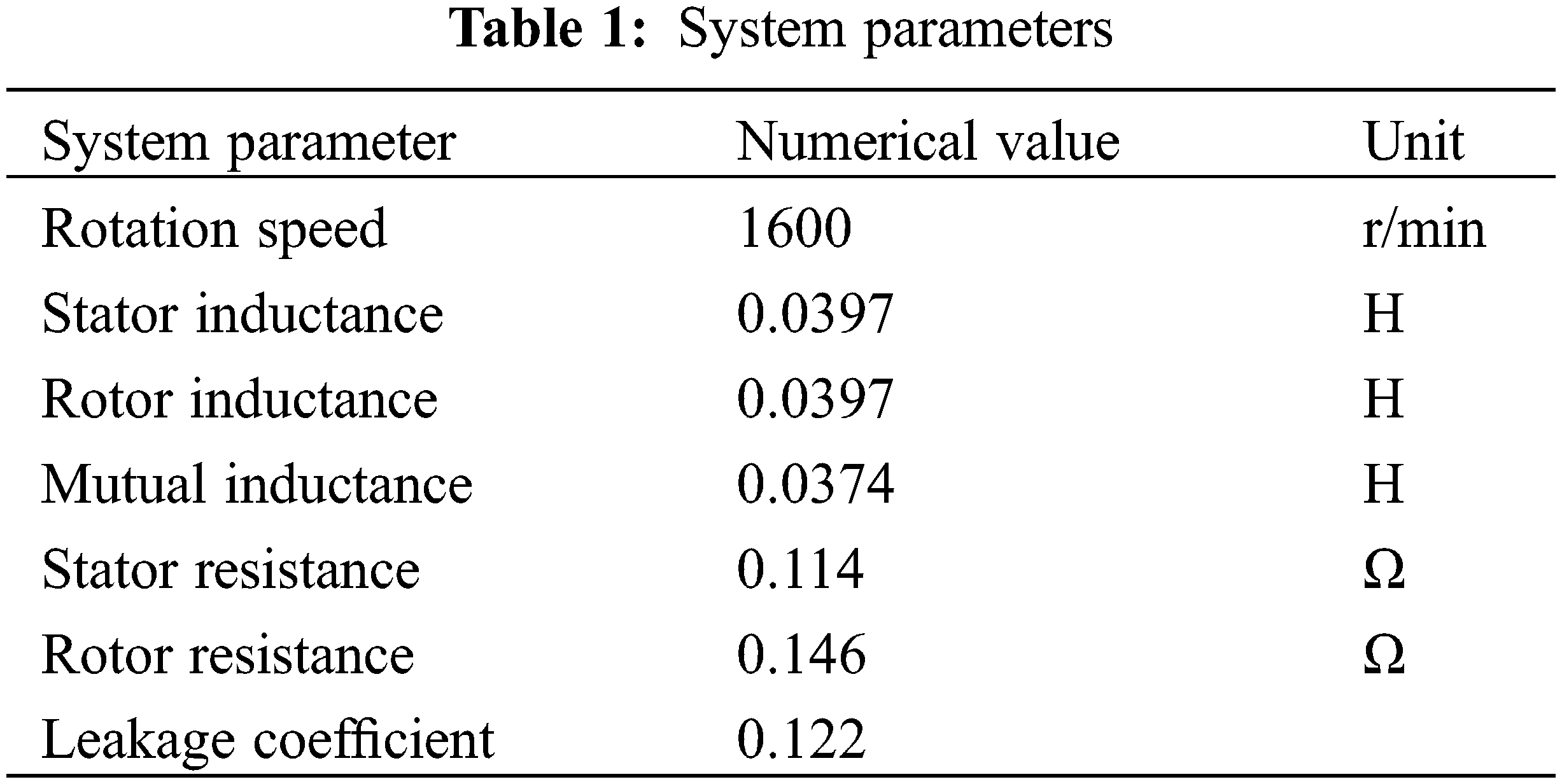
To verify the performance of the proposed fault detection scheme, the generator excitation system is simulated in Matlab/Simulink by using the model in Eq. (4). The short-circuit coefficient in the excitation system is 0.05, and the other system parameters are shown in Table 1.
The external disturbance of the system is set as sinusoidal function δ = 5 sin 10t, Its upper and lower bounds are
3.1 Comparative Analysis of Fault Diagnosis Based on Residual Interval Observer and Traditional Excitation Current Diagnosis Effect
The currents of the excitation system before and after the short-circuit fault occurs are shown in Figs. 3a and 3b.
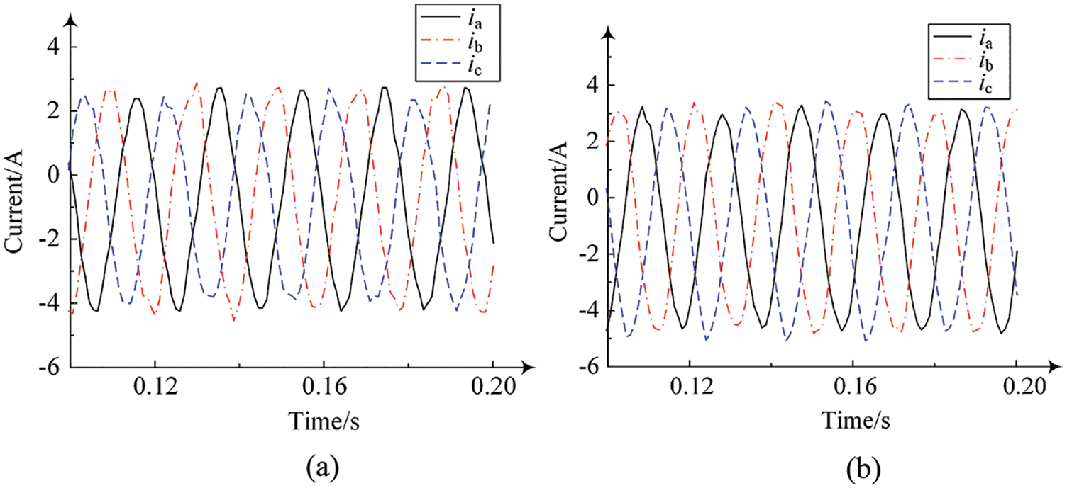
Figure 3: (a) Current signal of excitation system without fault (b) Current signal of rotor winding with short-circuit fault
It can be seen from the comparison of Figs. 3a and 3b that after the rotor winding short-circuit fault occurs, the current of the excitation system shows an increasing trend, but the current waveform changes little and still shows a sinusoidal trend. It is difficult to identify the rotor winding short-circuit weak fault in time without careful comparison between the waveform before and after fault occurs. As a, result, the time of fault cannot be accurately predicted, and the comparison between the waveform can hardly be carried out. On the other hand, the variation range of the three-phase current is not exactly the same due to the strong coupling effect between the electromagnetic fields of the excitation system, and it is inaccurate to set a uniform threshold for single-phase current. Therefore, it is necessary to convert the current in abc coordinate system into the dq coordinate system to formulate the upper and lower bounds of current fluctuation. When there is no fault in excitation system, the upper and lower bounds of the d axis current are shown in Fig. 4.
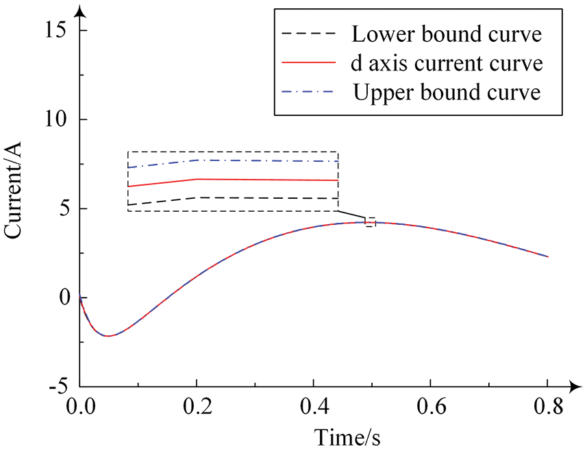
Figure 4: d axis current with upper and lower bounds without fault in the excitation system
As can be seen from Fig. 4, when the excitation system is free of fault, the d axis current fluctuates within the given upper and lower limits and gradually tends to be stable. When t = 6 s, the rotor winding short-circuit fault is introduced into the system. Afterwards, the d axis current is shown in Fig. 5.
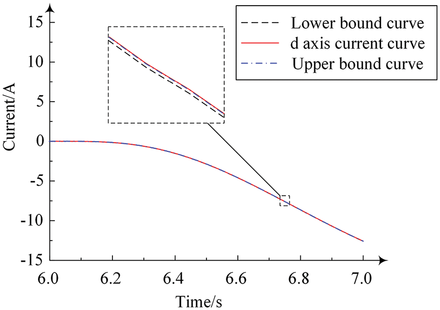
Figure 5: d axis current with upper and lower bounds in the case of rotor winding inter-turn short circuit fault in excitation system
It can be seen from Fig. 5 that after the fault is introduced, the d axis current fluctuates greatly, and the variation range of the main function curve exceeds the upper and lower bounds between 6–7 s. However, the distance between the upper and lower bounds and the main function curve is very close, so it is difficult to find out the exact time when the state parameters exceed the upper and lower bounds. If a fixed threshold is set for the d axis current for fault diagnosis, then frequent alarms will happen when the fault current signal fluctuates near the upper and lower bound functions (e.g., between 6–7 s in Fig. 5), and accurate fault judgment cannot be made. The efficiency of fault identification is low, and it is not conducive to the review and inspection of system status. Then the residual of the d axis current is calculated through the state observer proposed in this paper, and the results are shown in Fig. 6.

Figure 6: Interval observer residuals under inter-turn short circuit fault of rotor winding of excitation system
It can be seen from Fig. 6 that when there is no fault before t = 6 s, the upper bound of residual is always greater than zero and the lower bound of residual is always less than zero. When the fault occurred at t = 6 s, the upper and lower bounds of residuals increased synchronously. When t = 6.3 s, the lower bound of residual exceeds 0 and the data shows a monotonic increasing trend. Then the fault is detected and the alarm is given. Therefore, the fault is detected at t = 6.3 s by the observer designed in this paper without repeated fluctuation, and the fault determination is not affected by the current fluctuation. It can be seen that compared with the judgment method directly based on the three-phase current waveform and the method of the setting threshold for the dq axis current fluctuation, the fault identification speed of the state observer proposed in this paper is faster and the fault diagnosis effect is better.
3.2 Comparative Analysis of Diagnosis Effect with Different Short Circuit Turns
The short-circuit coefficient is then changed, and set as μ = 0.03 and μ = 0.1 respectively. The previous calculation examples are repeated to obtain the three-phase current of the excitation system under the inter turn short-circuit fault of rotor winding, as shown in Fig. 7.
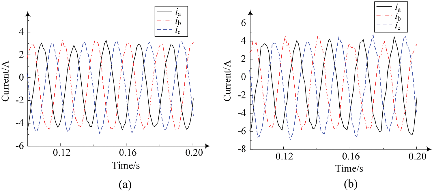
Figure 7: (a) Fault current signal when μ = 0.03 (b) Fault current signal when μ = 0.1
As can be seen from Fig. 7, when μ = 0.03 and μ = 0.1, there is no obvious change in the waveform of the three-phase current signal of the excitation system, only the variation amplitudes are different. Compared with the results in Fig. 3, it can be seen that the variation amplitude of excitation system current increases with the increase of short-circuit coefficient. When the number of short-circuit turns increases, the excitation current waveform fluctuates irregularly at the peaks and troughs, and the changes can be regarded as a basis for fault diagnosis. However, the fault diagnosis based on historical data and the experience put forward higher requirements for the data and personnel, and the fault diagnosis efficiency is low. When the residual interval observer proposed in this paper is adopted, and the fault is also introduced at t = 6 s, the residual variation of the interval observer under different short-circuit coefficients are shown in Fig. 8.

Figure 8: Interval observer residuals under different short-circuit turns coefficients
As can be seen from Fig. 8, under different short-circuit turns coefficients, the upper and lower bounds of the interval observer residual rise synchronously after the fault is introduced. With the increase of the short-circuit coefficient, the increase rate of the upper and lower bounds of the interval observer residual accelerates, and the time for the lower bound of the residual to exceed 0 shortens. The short-circuit weak fault can be detected when the coefficient of short-circuit is only 0.03, and there is little difference in the efficiency of fault diagnosis under different short-circuit turns. Therefore, it can be implied that the residual interval observer is high in fault sensitivity and diagnosis accuracy.
To further verify the correctness of the mathematical model of rotor winding short-circuit fault of excitation system based on the residual interval observer, the current characteristics are studied in the experiment. The corresponding experimental platform is built as shown in Fig. 9, and the specific parameters are shown in Table 2.

Figure 9: Experimental system diagram
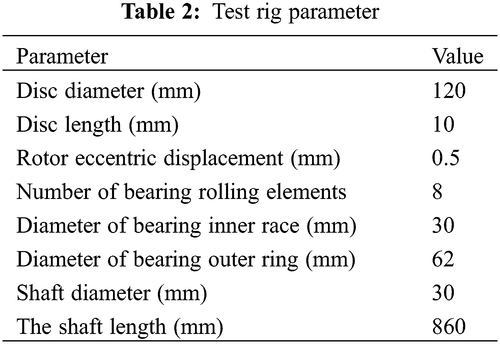
In Fig. 9, the excitation system is simulated by a three-phase motor, and the experimental platform is composed of motor, coupling and rotor system. The motor speed can be adjusted manually, and the current sensors are used to measure the current of axis a, b, and c. Then the inter-turn short circuit fault of rotor winding is introduced at t = 6 s, the short circuit coefficient is μ = 0.03, and the experimental current signal is shown in Fig. 10.
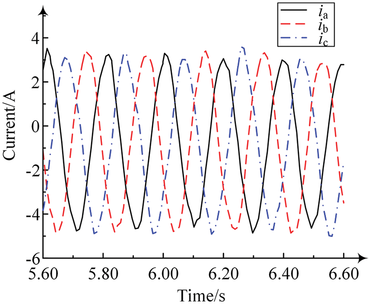
Figure 10: Experimental current signal
It can be seen from Fig. 10 that the three-phase current signal of the excitation system with the inter-turn short circuit fault of rotor winding collected is similar to the sinusoidal signal law. Since the fault is relatively weak, there is no significant changes in the three phase currents. Therefore, it is impossible to accurately judge whether the inter-turn short circuit fault occurs and the occurrence time of the fault from the three-phase current signal waveform. Then the current signal is used to calculate the current residual through the residual interval observer proposed in this paper, and the calculation results of the d axis residual are shown in the Fig. 11.
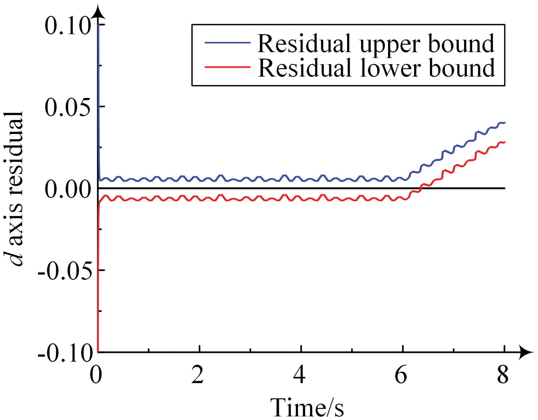
Figure 11: Experimental data of d axis residual
It can be seen from Fig. 11 that after the fault is introduced at t = 6 s, the upper and lower bounds of the system residual increase rapidly, and the lower bound of the residual increases to 0 when t = 6.3 s and continues to rise with time. There is no obvious drop back below 0 to affect the diagnosis conclusion. Therefore, when t = 6.3 s, the fault alarm can be made by the observer. Compared with the simulation results, the experimental results fluctuate more greatly, but the overall trend is similar. It is verified that the proposed residual interval observer is high in fault detection accuracy, fast in detection time, and high in efficiency.
In this paper, a residual interval observer is designed for the diagnosis of the short-circuit fault of rotor winding aiming at problem that the weak faults can hardly be detected in time. In stable working conditions, the electromagnetic decoupling is carried out through modeling and coordinate transformation, and the current residual of the monitoring system is proposed to improve the diagnosis accuracy. Theoretical and experimental studies show that it is difficult to identify the weak fault only by observing the excitation current signal, but rapid fault detection can be realized when the residual interval observer is applied. When the number of short-circuit turns increases, the detection speed is faster, and no false alarm is found to affect the weak fault detection. Under the premise of stable working conditions and sinusoidal external interference, the residual interval observer brings a more precise weak fault detection, and the detection speed is also faster. The residual interval observer proposed in this paper provide important theoretical and technical basis for the operation and maintenance of excitation system. Unstable working conditions and irregular external interference may lead to fluctuations in observed residuals and even false alarms, and it needs to be optimized in the future works.
Funding Statement: The authors would like to thank the financial supports from National Science Foundation of China (Grant No. 51777121).
Conflicts of Interest: The authors declare that they have no conflicts of interest to report regarding the present study.
References
1. Fukaume, S., Nagasaki, Y., Tsuda, M. (2022). Stable power supply of an independent power source for a remote island using a Hybrid Energy Storage System composed of electric and hydrogen energy storage systems. International Journal of Hydrogen Energy, 47(29), 13887–13899. https://doi.org/10.1016/j.ijhydene.2022.02.142 [Google Scholar] [CrossRef]
2. Zhang, L. Y., Li, X., Liang, S. W., Han, D. S. (2022). Research on the influence of electric railway bilateral power supply on power system and countermeasures. International Journal of Electrical Power & Energy Systems, 137(12), 107769. https://doi.org/10.1016/j.ijepes.2021.107769 [Google Scholar] [CrossRef]
3. Yanine, F., Sanchez-Squella, A., Barrueto, A., Tosso, J., Cordova, F. M. et al. (2018). Reviewing homeostasis of sustainable energy systems: How reactive and predictive homeostasis can enable electric utilities to operate distributed generation as part of their power supply services. Renewable and Sustainable Energy Reviews, 81(3), 2879–2892. https://doi.org/10.1016/j.rser.2017.06.094 [Google Scholar] [CrossRef]
4. Ribeiro, M. V., Fernandes, V., Monteiro, H. L. M., Cravo, N., DeOliveira, E. J. (2022). Benefits of energy recovery from the undesirable components of electric signals in electric power systems. International Journal of Electrical Power & Energy Systems, 138(6), 107323. https://doi.org/10.1016/j.ijepes.2021.107323 [Google Scholar] [CrossRef]
5. Zorig, A., Kia, S. H., Chouder, A., Rabhi, A. (2022). A comparative study for stator winding inter-turn short-circuit fault detection based on harmonic analysis of induction machine signatures. Mathematics and Computers in Simulation, 196(5), 273–288. https://doi.org/10.1016/j.matcom.2022.01.019 [Google Scholar] [CrossRef]
6. Kawabe, K., Masuda, M., Nanahara, T. (2020). Excitation control method based on wide-area measurement system for improvement of transient stability in power systems. Electric Power Systems Research, 188, 106568. [Google Scholar]
7. Hasanien, H. M., El-Fergany, A. A. (2019). Salp swarm algorithm-based optimal load frequency control of hybrid renewable power systems with communication delay and excitation cross-coupling effect. Electric Power Systems Research, 176, 105938. [Google Scholar]
8. Kumar, L., Kumar, P., Satyajeet, Narang, D. (2018). Tuning of fractional order PIλDμ controllers using evolutionary optimization for PID tuned synchronous generator excitation system. International Federation of Automatic Control-PapersOnLine, 51(4), 859–864. [Google Scholar]
9. Mseddi, A., Ballois, S. L., Aloui, H., Vido, L. (2019). Robust control of a wind conversion system based on a hybrid excitation synchronous generator: A comparison between H∞ and CRONE controllers. Mathematics and Computers in Simulation, 158, 453–476. [Google Scholar]
10. Gao, A. R., Feng, Z. P., Liang, M. (2021). Permanent magnet synchronous generator stator current AM-FM model and joint signature analysis for planetary gearbox fault diagnosis. Mechanical Systems and Signal Processing, 149, 107331. [Google Scholar]
11. Wu, Y., Jiang, B., Lu, N. (2019). A descriptor system approach for estimation of incipient faults with application to high-speed railway traction devices. IEEE Transactions on Systems, Man, and Cybernetics: Systems, 49(10), 2108–2118. https://doi.org/10.1109/TSMC.2017.2757264 [Google Scholar] [CrossRef]
12. Li, P., Guo, P. C. (2022). Diagnosis of interturn faults of voltage transformer using excitation current and phase difference. Engineering Failure Analysis, 134(1), 105979. https://doi.org/10.1016/j.engfailanal.2021.105979 [Google Scholar] [CrossRef]
13. Ribeiro, J. C., Cardoso Jr, G., Silva, V. B., Oliveira, A. L., Ricciotti, A. C. D. et al. (2022). Paraconsistent analysis network for uncertainties treatment in electric power system fault section estimation. International Journal of Electrical Power & Energy Systems, 134, 107317. https://doi.org/10.1016/j.ijepes.2021.107317 [Google Scholar] [CrossRef]
14. Abad, H. B. B., Ojaghi, M., Taheri, A. (2021). Efficient index for detecting the stator winding interturn fault in six-phase squirrel-cage induction motors. Measurement, 184, 109912. [Google Scholar]
15. Vaish, R., Dwivedi, U. D., Tewari, S., Tripathi, S. M. (2021). Machine learning applications in power system fault diagnosis: Research advancements and perspectives. Engineering Applications of Artificial Intelligence, 106, 104504. https://doi.org/10.1016/j.engappai.2021.104504 [Google Scholar] [CrossRef]
16. Zare, F., Gheidari, Z. N., Tootoonchian, F. (2019). The effect of winding arrangements on measurement accuracy of sinusoidal rotor resolver under fault conditions. Measurement, 131(3/4), 162–172. https://doi.org/10.1016/j.measurement.2018.08.074 [Google Scholar] [CrossRef]
17. Wu, Y. K., Jiang, B., Wang, Y. L. (2020). Incipient winding fault detection and diagnosis for squirrel-cage induction motors equipped on CRH trains. International Society of Automation Transactions, 99(5), 488–495. https://doi.org/10.1016/j.isatra.2019.09.020 [Google Scholar] [PubMed] [CrossRef]
18. Li, J. Q., Liu, J., Chen, Y. T. (2022). A fault warning for inter-turn short circuit of excitation winding of synchronous generator based on GRU-CNN. Global Energy Interconnection, 5(2), 236–248. https://doi.org/10.1016/j.gloei.2022.04.020 [Google Scholar] [CrossRef]
19. Forstner, G., Kugi, A., Kemmetmüller, W. (2021). Fault-tolerant torque control of a three-phase permanent magnet synchronous motor with inter-turn winding short circuit. Control Engineering Practice, 113(3), 104846. https://doi.org/10.1016/j.conengprac.2021.104846 [Google Scholar] [CrossRef]
20. Yang, J. W., Dai, Z. Y., Zhang, Z. (2020). Modeling and fault diagnosis of multi-phase winding inter-turn short circuit for five-phase PMSM based on improved trust region. Microelectronics Reliability, 114, 113778. [Google Scholar]
21. Sarkar, S., Purkait, P., Das, S. (2021). NI CompactRIO-based methodology for online detection of stator winding inter-turn insulation faults in 3-phase induction motors. Measurement, 182(1), 109682. https://doi.org/10.1016/j.measurement.2021.109682 [Google Scholar] [CrossRef]
22. Faiz, J., Keravand, M., Ghasemi-Bijan, M., Cruz, S. M., Bandar-Abadi, M. (2016). Impacts of rotor inter-turn short circuit fault upon performance of wound rotor induction machines. Electric Power Systems Research, 135, 48–58. https://doi.org/10.1016/j.epsr.2016.03.007 [Google Scholar] [CrossRef]
23. Li, X., Shao, H. D., Lu, S. L., Xiang, J. W., Cai, B. P. (2022). Highly-efficient fault diagnosis of rotating machinery under time-varying speeds using LSISMM and small infrared thermal images. Institute of Electrical and Electronics Engineers Transactions on Systems, Man, and Cybernetics: Systems, 1–13. https://doi.org/10.1109/TSMC.2022.3151185 [Google Scholar] [CrossRef]
24. Zhao, X. L., Yao, J. Y., Deng, W. X., Ding, P., Ding, Y. F. et al. (2022). Intelligent fault diagnosis of gearbox under variable working conditions with adaptive intraclass and interclass convolutional neural network. IEEE Transactions on Neural Networks and Learning Systems, 1–15. https://doi.org/10.1109/TNNLS.2021.3135877 [Google Scholar] [PubMed] [CrossRef]
25. Barron, A. M., Tinoco, G. T., Hernandez, J. R. R., Rodriguez, M. V., Lieberman, D. G. (2021). A neural network-based model for MCSA of inter-turn short-circuit faults in induction motors and its power hardware in the loop simulation. Computers & Electrical Engineering, 93, 107234. [Google Scholar]
26. Sanchez, B., Ordaz, P., Poznyak, A. (2022). Model based reduced-order observers for a class of mechatronic systems with mitigation of disturbances effects using the Attractive Ellipsoid Method. Mechatronics, 84(6), 102778. https://doi.org/10.1016/j.mechatronics.2022.102778 [Google Scholar] [CrossRef]
27. Guo, X. G., Tian, M. E., Li, Q., Ahn, C. K., Yang, Y. H. (2020). Multiple-fault diagnosis for spacecraft attitude control systems using RBFNN-based observers. Aerospace Science and Technology, 106(9), 106195. https://doi.org/10.1016/j.ast.2020.106195 [Google Scholar] [CrossRef]
28. Dong, Z., Li, B. W., Li, J. Y., Huang, X. J., Zhang, Z. Y. (2022). Online reliability assessment of energy systems based on a high-order extended-state-observer with application to nuclear reactors. Renewable and Sustainable Energy Reviews, 158, 112159. https://doi.org/10.1016/j.rser.2022.112159 [Google Scholar] [CrossRef]
29. Guo, M. X., Zhu, S., Liu, X. Y. (2022). Observer-based state estimation for memristive neural networks with time-varying delay. Knowledge-Based Systems, 246(5), 108707. https://doi.org/10.1016/j.knosys.2022.108707 [Google Scholar] [CrossRef]
30. Zhang, M. D., Wang, Z. Y., Wang, Y., Park, J. H., Ji, Z. C. (2022). Interval observer filtering-based fault diagnosis method for linear discrete-time systems with dual uncertainties. Journal of the Franklin Institute, 359(2), 1626–1648. https://doi.org/10.1016/j.jfranklin.2021.11.018 [Google Scholar] [CrossRef]
31. Chen, Y., Zhang, J. J., Chen, Z. Y. (2020). Current observer-based online open-switch fault diagnosis for voltage-source inverter. The International Society of Automation Transactions, 99, 445–453. [Google Scholar]
32. Venkateswaran, S., Sheriff, M. Z., Wilhite, B., Kravaris, C. (2021). Design of functional observers for fault detection and isolation in nonlinear systems in the presence of noises. Journal of Process Control, 108, 68–85. https://doi.org/10.1016/j.jprocont.2021.10.001 [Google Scholar] [CrossRef]
33. Zhang, X., Wang, Q. J., Shen, H. M. (2018). A multi-field coupled mechanical-electric-magnetic-chemical-thermal (MEMCT) theory for material systems. Computer Methods in Applied Mechanics and Engineering, 341(1064), 133–162. https://doi.org/10.1016/j.cma.2018.07.005 [Google Scholar] [CrossRef]
34. Wang, Z. Z., Zhou, J., Rizzoni, G. (2022). A review of architectures and control strategies of dual-motor coupling powertrain systems for battery electric vehicles. Renewable and Sustainable Energy Reviews, 162(sup1), 112455. https://doi.org/10.1016/j.rser.2022.112455 [Google Scholar] [CrossRef]
Cite This Article
 Copyright © 2023 The Author(s). Published by Tech Science Press.
This work is licensed under a Creative Commons Attribution 4.0 International License , which permits unrestricted use, distribution, and reproduction in any medium, provided the original work is properly cited.
 Downloads
 Citation Tools