
 Submit a Paper
 Propose a Special lssue
 Open Access
ARTICLE

Assessment of the Influence of Tunnel Settlement on Operational Performance of Subway Vehicles
1 China Communications Construction Rail Transit Subsidiary, Beijing, 100000, China
2 China Communications Construction Strait Construction Investment Development Co., Ltd., Fuzhou, 350000, China
3 School of Civil Engineering, Fujian University of Technology, Fuzhou, 350118, China
* Corresponding Author: Wei Zhang. Email:
(This article belongs to the Special Issue: Health Monitoring and Rapid Evaluation of Infrastructures)
Structural Durability & Health Monitoring 2024, 18(1), 55-71. https://doi.org/10.32604/sdhm.2023.044832
Received 09 August 2023; Accepted 27 October 2023; Issue published 11 January 2024
 View Full Text
 Download PDF
Abstract
In the realm of subway shield tunnel operations, the impact of tunnel settlement on the operational performance of subway vehicles is a crucial concern. This study introduces an advanced analytical model to investigate rail geometric deformations caused by settlement within a vehicle-track-tunnel coupled system. The model integrates the geometric deformations of the track, attributed to settlement, as track irregularities. A novel “cyclic model” algorithm was employed to enhance computational efficiency without compromising on precision, a claim that was rigorously validated. The model’s capability extends to analyzing the time-history responses of vehicles traversing settlement-affected areas. The research primarily focuses on how settlement wavelength, amplitude, and vehicle speed influence operational performance. Key findings indicate that an increase in settlement wavelength can improve vehicle performance, whereas a rise in amplitude can degrade it. The study also establishes settlement thresholds, based on vehicle operation comfort and safety. These insights are pivotal for maintaining and enhancing the safety and efficiency of subway systems, providing a valuable framework for urban infrastructure management and long-term maintenance strategies in metropolitan transit systems.Keywords
As urban rail transit operations densify and operational speeds continue to improve, the safety and stability requisites for these systems are becoming increasingly stringent. Currently, shield tunneling, with its distinctive advantages, has progressively become the principal technical method for underground space development. Factors such as falling groundwater levels leading to segment subsidence, groundwater-triggered segment floatation in water-rich strata, and soil deposition-induced segment subsidence, can impact the smoothness of subway lines. This may result in a gamut of issues, including degradation of train running smoothness, comfort, and safety [1–6].
In light of the issue of subway tunnel settlement, numerous researchers have conducted studies. Guo et al. [7] utilized numerical calculations to investigate the development of surface settlement during the construction of subway stations. They posited that the critical phase for controlling surface settlement was the pilot tunnel excavation and arch installation. Topal et al. [8] examined surface deformations at four different points along a metro line on the European side of Istanbul. Their goal was to identify a reliable method for estimating settlement resulting from shallow underground excavations in high-risk areas. Bai et al. [9] used Shenyang Metro Line 4 as a case study, where they discussed the construction of a small tube top beam method and analyzed the settlement of the tube top, beam, middle column, and side pile. Surface settlement was monitored throughout the process. Luo et al. [10] used the backdrop of a newly constructed subway station and employed ROCSCIENCE software in conjunction with on-site monitoring techniques. Their focus was on the study of settlement and deformation of the pile foundation and building prompted by foundation pit excavation in a subway station.
Track smoothness significantly affects the operational performance of vehicles, and this subject has been the focus of extensive research [11–13]. In relation to the impact of settlement on vehicle performance, Zhong et al. [14] established a bridge-vehicle model, taking into account the effect of foundation settlement by employing the principle of virtual engineering. They investigated the interactive response between bridge settlement and vehicles. The validity and accuracy of their model were confirmed through theoretical and numerical outcomes. The Newmark-β method was then used to simulate the effects of settlement mode, vehicle speed, road roughness, and boundary conditions, using this model.
To gauge the influence of subgrade differential settlement on the dynamic performance of the rail-plate track system, Guo et al. [15] formulated a comprehensive theoretical model that considered nonlinear subgrade support and track weight. The model accounted for the damping effect of the composite track structure on subgrade settlement. After assessing the dynamic performance indices of high-speed trains in terms of operational safety, ride comfort, and dynamic performance of infrastructure, they derived the control threshold for subgrade settlement in China’s high-speed railway slab track system.
Sun et al. [16] proposed an enhanced vehicle-track coupling dynamic model that considered settlement. Central to this model was an iterative method used to map the relationship between ballast settlement and track and sleeper deflection. The efficacy of the proposed method was verified through comparison with the computational results from both the finite element method and the equilibrium state of the ballast-bearing track. Using the proposed method and dynamic model, the static deflection of track and sleeper, as well as the dynamic response of the rail-rail coupling system, were numerically analyzed.
The main contributions of the paper are as follows:
• An analytical equation for rail deformation caused by shield tunneling settlement or uplift is proposed.
• An efficient calculation model for vehicle-track-shield tunnel segment-soil dynamic system is proposed.
• The impact of different wavelengths and amplitudes of settlement and on vehicle operation performance are discussed.
The paper will elaborate on the following aspects: first, the analytical equation for rail deformation caused by the settlement of shield tunnel segments is derived; second, the efficient calculation model for vehicle-track-shield tunnel segment-soil dynamic system is introduced; finally, the effects of settlement wavelength, amplitude, and vehicle speed on operational performance are discussed.
2 Track Deformation Induced by Tunnel Settlement
To expediently determine track irregularity prompted by tunnel settlement, an analytical model of settlement-track irregularity was devised. The resolution of the model was premised on the following assumptions: (1) The mortar layer beneath the track plate is treated as a Winkler elastic foundation; (2) No coupling relationship exists between the deformation of the shield segment and the track.
According to the relevant principles of material mechanics, the vertical upward displacement zr,i of the rail at the force position of the i-th fastener can be expressed as:
where Fr,i denotes i-th fastener force; xr,i denotes the distance between i-th fastener and left end of rail; lf denotes the distance of the two adjacent fastener; Er denotes elastic modulus of rail; lr denotes total length of rail; Ir denotes the cross section moment of inertia of the rail.
The corresponding rail displacement at each fastener position can be obtained from the above formula, which is now integrated into a matrix form and expressed as follows:
where Zr denotes the rail deformation matrix of Fr,i, Fr denotes the fastener force matrix; R is the correlation matrix of
3 Vehicle-Track-Tunnel Coupled System
The vehicle model was conceptualized as a multi-rigid-body-spring-damping system, wherein each vehicle consisted of a car body, two bogies, and four wheel-sets, all of which were deemed rigid bodies. The suspension system linking the car body and bogie (secondary suspension), and the one between the bogie and wheel set (primary suspension), were depicted through spring stiffness viscous damping, as illustrated in Fig. 1. Utilizing the principle of elastic potential energy invariance, the dynamic equation governing the vehicle’s motion can be derived [17].
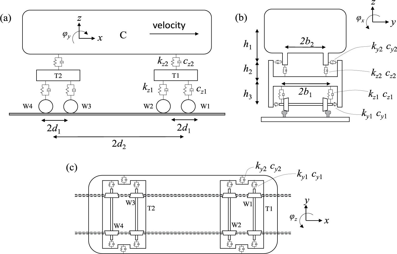
Figure 1: Vehicle model
Mv is the mass matrix of vehicle, and it can be written as:
where n denotes there are n carriages totally; Mvi denotes ith mass matrix of vehicle, and it can be represented as:
where m and J denote mass and moment of inertia respectively, and the subscript c, t and w denote carbody, bogie and wheelset, respectively.
Kv denotes stiffness of vehicle, and it can be represented as:
where Kvi denotes stiffness matrix of ith carriage, and it can be represented as:
where k denotes the stiffness of suspension, and the subscripts y and z denote lateral and vertical direction; the subscripts 1 and 2 denote primary and secondary suspension, respectively.
The soil and shield segments can be represented using the finite element software ABAQUS, as illustrated in Fig. 2. Both of these components are modeled as solid elements. A “tie contact” is established between the shield segments and the soil, meaning that slip between these elements is not considered. The outer boundary of the soil is fixed. The front and rear sides of the soil and shield are coupled to create a state that resembles “common nodes”. After the modeling process is complete, the stiffness and mass matrices of the soil shield model can be derived.
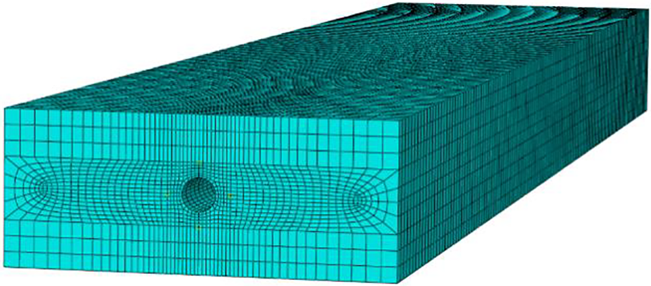
Figure 2: Finite element model of soil shield segment
Both the rail and the track are modeled using Euler beam elements. The fastener connecting the rail and the track is simulated via a spring-viscous damper, while the connection between the rail plate and the shield segment is also represented through a spring-viscous damper.
Fig. 3 illustrates how the joint points at the front and rear ends of the rail and track are “common nodes”. The number 1 node on the left side serves as the starting node, while the number 1 node on the right is the virtual node. This virtual node shares its position with the number 1 node on the left, thereby creating a closed-loop structure. For more detailed information about this arrangement, please refer to the work of Zhou et al. [18,19].
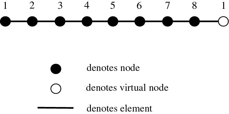
Figure 3: Cyclic structure model
The dynamic equation of the rail-shield cyclic tunnel model obtained is shown as follows:
where Mts and Kts are the mass matrix and stiffness matrix of rail-shield circulation tunnel model, Cts is the damping matrix, and it can be obtained by Rayleigh damping; Xts, Ẍts, Ẍts and Xts denotes the acceleration, velocity and displacement vector of rail-shield circulation tunnel system; Fts is the load array acting on the rail-shield cyclic tunnel system.
The vehicle and rail-shield cyclic tunnel model can be coupled according to the wheel-rail contact. According to Eqs. (6) and (24), the coupled system of vehicle-track-tunnel coupled system model can be obtained, and the wheel-rail contact force can be calculated as follows:
The explicit integration method for gradually solving the above equation system [20].
The selected example is the section from Changle Binhai Express Airport Station to the middle wind shaft, as shown in Fig. 4. The finite element model for this example is composed of four main parts: soil mass, pipe segment, track, and rail. In this cyclic model, a soil mass with dimensions of length × width × height = 300 m × 100 m × 40 m is chosen for computation.
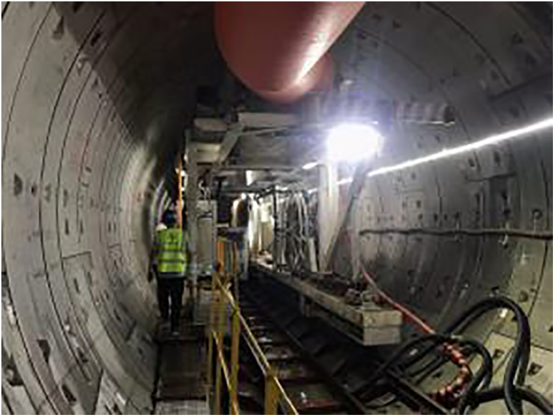
Figure 4: Shield tunnel
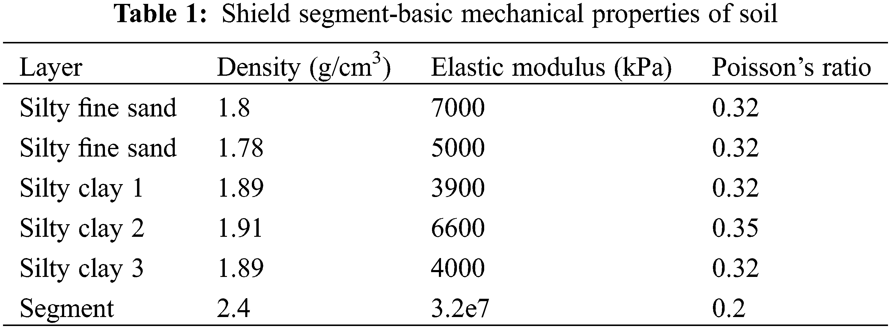
This soil mass is divided into five distinct layers: silty sand, muddy sand, and three layers of silty clay, each with different attributes, starting from the top. The silty sand layer has a height of 5 m, and the muddy sand layer is 10 m high. The three layers of silty clay, each with unique properties, have respective heights of 15, 5, and 5 m. The segments’ outer diameter is 8.3 m, while the inner diameter is 7.5 m.
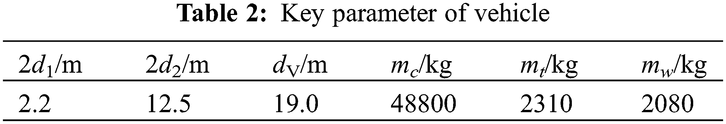
Table 1 provides the basic mechanical properties for each component. The vehicle employed in the model corresponds to common subway vehicle models, and key parameters for the vehicle are given in Table 2.
The vehicle-track-tunnel coupled system model is intricate, involving multiple layers of system dynamics. To validate the accuracy of our system dynamic model’s calculation results, we compared them to the dynamic response results provided by Xia et al. [21]. The case in consideration was a six-car assembled AH vehicle running at a speed of 80 km/h, with track irregularities generated using the American track spectrum. The comparison results are presented in Fig. 5. Our model’s results closely match the amplitude and trends found in the referenced literature, thereby affirming the accuracy of the calculations made by our proposed model.
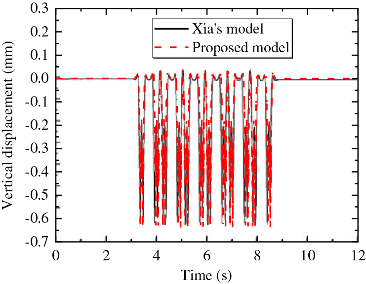
Figure 5: Validation of literature results
Due to the ongoing construction of the tunnel, the current geometric deformation mainly relies on numerical calculations and settlement measurements, without involving track irregularities. The initial track irregularity in the manuscript was simulated using the German low interference spectrum, and the irregularity caused by settlement was obtained through assumptions. The German low interference spectrum can be written as:
where Ω denotes the spatial frequency; Ωc equals to 0.8246 rad/m, Av equals to 1.080 × 10⁻⁶ m2·rad/m, Ωr equals to 0.0206 rad/m. The trigonometric series method is used to simulate the track irregularity samples.
Tunnel settlement reasons are multifaceted, leading to various forms of uneven settlement. Theoretically, this inhomogeneous sedimentation can be broadly classified into two types: “sudden” and “gradual”. To simulate the impact of gradual tunnel settlement on vehicle running performance, we used a concave full-wave cosine curve [15]. The formulation for the curve is as follows:
where Z is the settlement value, x is the coordinate of a longitudinal point along the route, s is the cosine type settlement wavelength, and A is settlement amplitude.
After obtaining the tunnel settlement values, the geometric deformation of the rail can be calculated using the analytical method described in Section 2. The accuracy of this analytical model was validated by comparing its results with a numerical example where the settlement wavelength (S) was 10 m and the amplitude (A) was 100 mm. The outcomes from the analytical model and the finite element model are displayed in Fig. 6. The results obtained through the analytical model align well with those from the finite element model, verifying the accuracy of the analytical model.
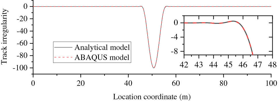
Figure 6: Comparison between analytical model and finite element model
In addition to the deformation induced by tunnel settlement, the track also possesses initial irregularities. These two factors were superimposed to create a compound irregularity. This compound irregularity was then input into the vehicle-track-tunnel dynamic simulation model to analyze the dynamic response of the vehicle.
Fig. 7 illustrates the composite track irregularity caused by a combination of initial track irregularity and tunnel settlement with an amplitude of 100 mm and a wavelength of 10m. The initial track irregularity oscillates between −10 and 10 mm in amplitude. At locations where settlement occurs, the amplitude of the irregularity becomes more pronounced. Furthermore, minor differences can be observed in the irregularities present in the left and right rails.
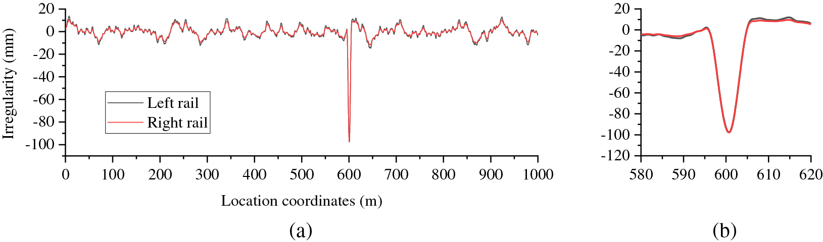
Figure 7: The compound irregularity: (a) global irregularity; (b) local irregularity
4.3 Analysis of Time History Response
The paper delves into the dynamic response of vehicles impacted by tunnel settlement through a time history response analysis. This analysis was based on a vehicle running at a calculated speed of 100 km/h, with a tunnel settlement wavelength (S) of 40 m and an amplitude (A) of 150 mm.
Fig. 8 shows the acceleration of the vehicle’s first car body and its corresponding track irregularity over time. The body acceleration encompasses the vertical acceleration above the front bogie (VAF), vertical acceleration at the center of gravity of the body (VAC), and roll acceleration (Roll).
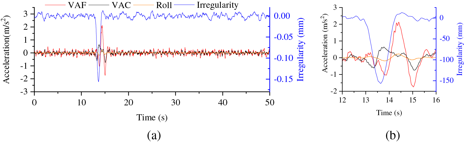
Figure 8: Time history of car-body acceleration and irregularity: (a) global; (b) local
Under regular operating conditions, the vehicle’s body oscillates due to the influence of track irregularities. Upon passing through the tunnel’s settlement area, the vehicle body’s acceleration experiences abrupt changes. Once the vehicle exits the tunnel’s settlement area, the body’s acceleration diminishes and gradually returns to its normal operating state.
The local response, as seen in Fig. 8b, indicates that both the vertical and roll acceleration of the car body are impacted by the settlement. Consequently, the acceleration of the vehicle above the bogie is greater than the acceleration at the center of gravity.
Fig. 9 depicts the time history of the wheel-rail contact force response and track irregularities. As evident from the graph, during regular operation, the wheel-rail force exhibits minor fluctuations under the influence of track irregularities. Upon the vehicle’s entry into the area affected by settlement, the variability of the vertical wheel-rail force augments, while the lateral wheel-rail force remains largely unchanged, a trend clearly demonstrated in Fig. 9b. Overall, although settlement influences the wheel-rail force, its impact remains relatively insignificant.
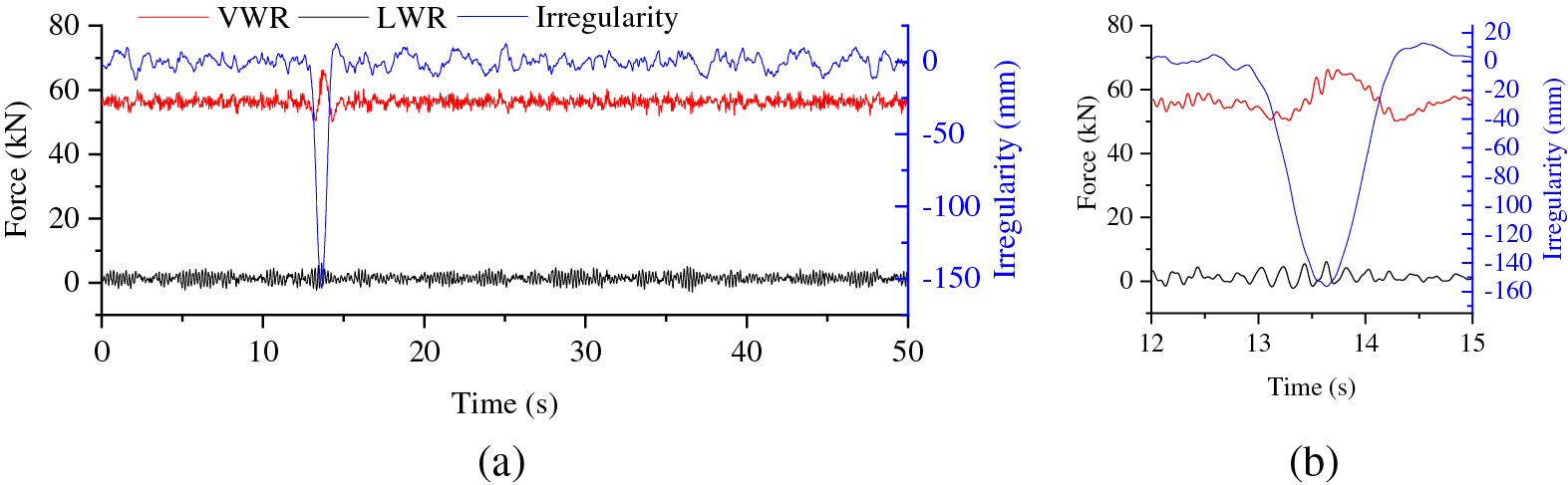
Figure 9: Time history of wheel-rail contact force and irregularity: (a) global; (b) local
Nadal index and wheel unloading are the most commonly used indexes to measure running safety. The Nadal index can be calculated by the following formula:
where Q is the lateral force acting on the wheel, and Q is the vertical force acting on the wheel.
The wheel unloading can be calculated by the following formula:
where ΔP is the vertical load reduction of wheel, and P is the static wheel load.
Fig. 10 illustrates the time history curve of the first wheelset’s unloading and the track irregularity excitation as the vehicle moves. In normal vehicle operation, the wheel unloading fluctuates within the range of −0.1 to 0.1, indicating satisfactory running safety performance. When the vehicle transits through the area affected by settlement, a slight change in wheel unloading is observed, further demonstrating that the settlement exerts minimal impact on the wheel-rail force of the vehicle.
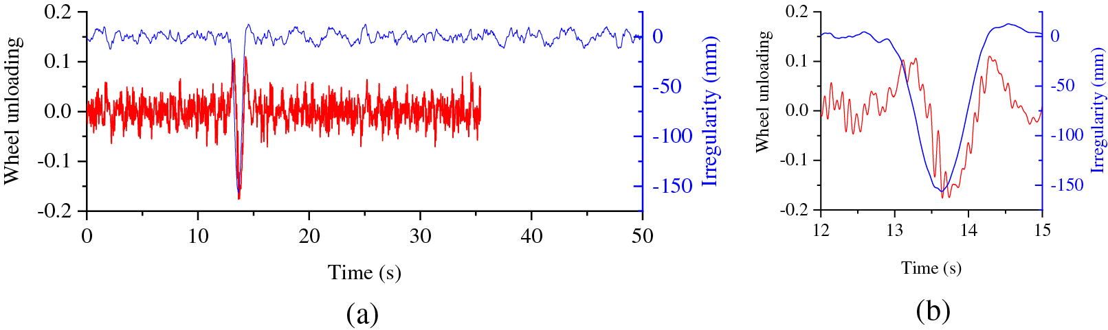
Figure 10: Time history of wheel unloading and irregularity: (a) global; (b) local
Fig. 11 presents the time history curve of the Nadal index in relation to track irregularity excitation. From this, it is apparent that the Nadal index remains largely unaffected by track irregularities prompted by settlement. Throughout the entire process, the Nadal index remains below 0.1, suggesting strong running safety performance. This can be attributed to the fact that in this scenario, settlement has a minimal impact on both lateral and vertical forces of the wheel-rail interaction. Given that the Nadal index is tied to these lateral and vertical forces, settlement has negligible influence on it.
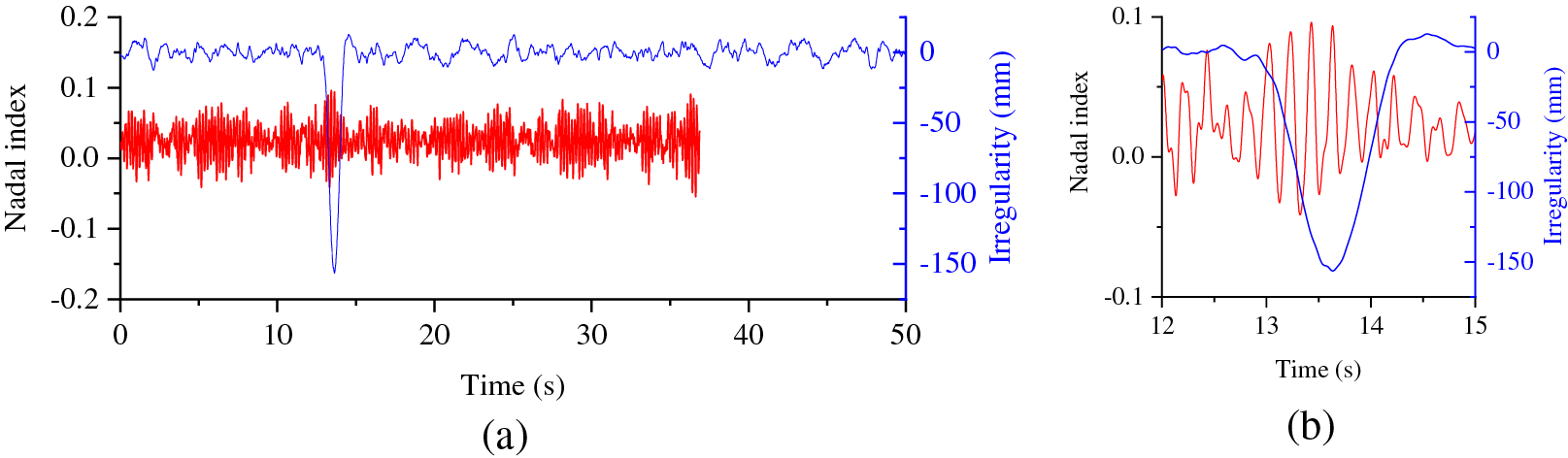
Figure 11: Time history of Nadal index and irregularity: (a) global; (b) local
4.4 Analysis of Influencing Factors
When the settlement amplitude increases, the amplitude of track irregularity correspondingly increases, and the dynamic response of the vehicle will increase. In an effort to thoroughly investigate the effect of tunnel settlement amplitude on vehicle performance, we computed the maximum acceleration of the car body above the front bogie, the maximum wheel unloading, and the maximum Nadal index for settlement wavelengths of 10, 40, and 70 m. The vehicle speed was held constant at 80 km/h. The results of these calculations can be seen in Fig. 12. It was observed that, regardless of settlement wavelength, the maximum acceleration of the vehicle body increased with an increase in settlement amplitude. Furthermore, the rate of increase was greater for smaller settlement wavelengths. As demonstrated in Fig. 12b, wheel unloading increased with an increase in settlement amplitude when the settlement wavelength was 10 m, with the increase being quite significant. However, when the settlement wavelength was either 40 or 70 m, there was no considerable change in wheel unloading. As shown in Fig. 12c, there was minimal change in the Nadal index.
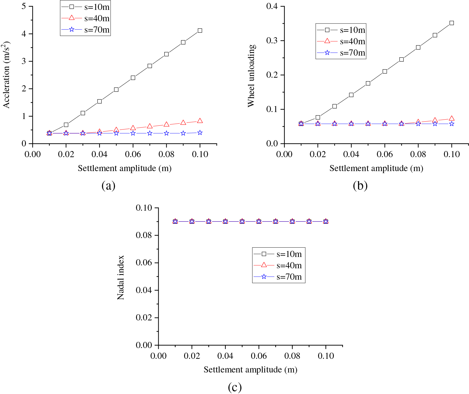
Figure 12: Influence of tunnel settlement amplitude on running performance: (a) acceleration; (b) wheel unloading; (c) Nadal index
In order to systematically investigate the effect of tunnel settlement wavelength on vehicle performance, we calculated the maximum acceleration of the car body above the front bogie, the maximum wheel unloading, and the maximum Nadal index for settlement amplitudes of 20, 50, and 80 mm. The results of these calculations are depicted in Fig. 13. As the settlement wavelength increases, both vehicle acceleration and wheel unloading decrease. This is because longer wavelengths can cause a more gradual and extended unevenness along the track and a smoother ride. However, the rate of decrease lessens with increasing wavelength, and a phenomenon that is more apparent when the amplitude is large. The Nadal index, on the other hand, shows minimal sensitivity to changes in settlement wavelength.
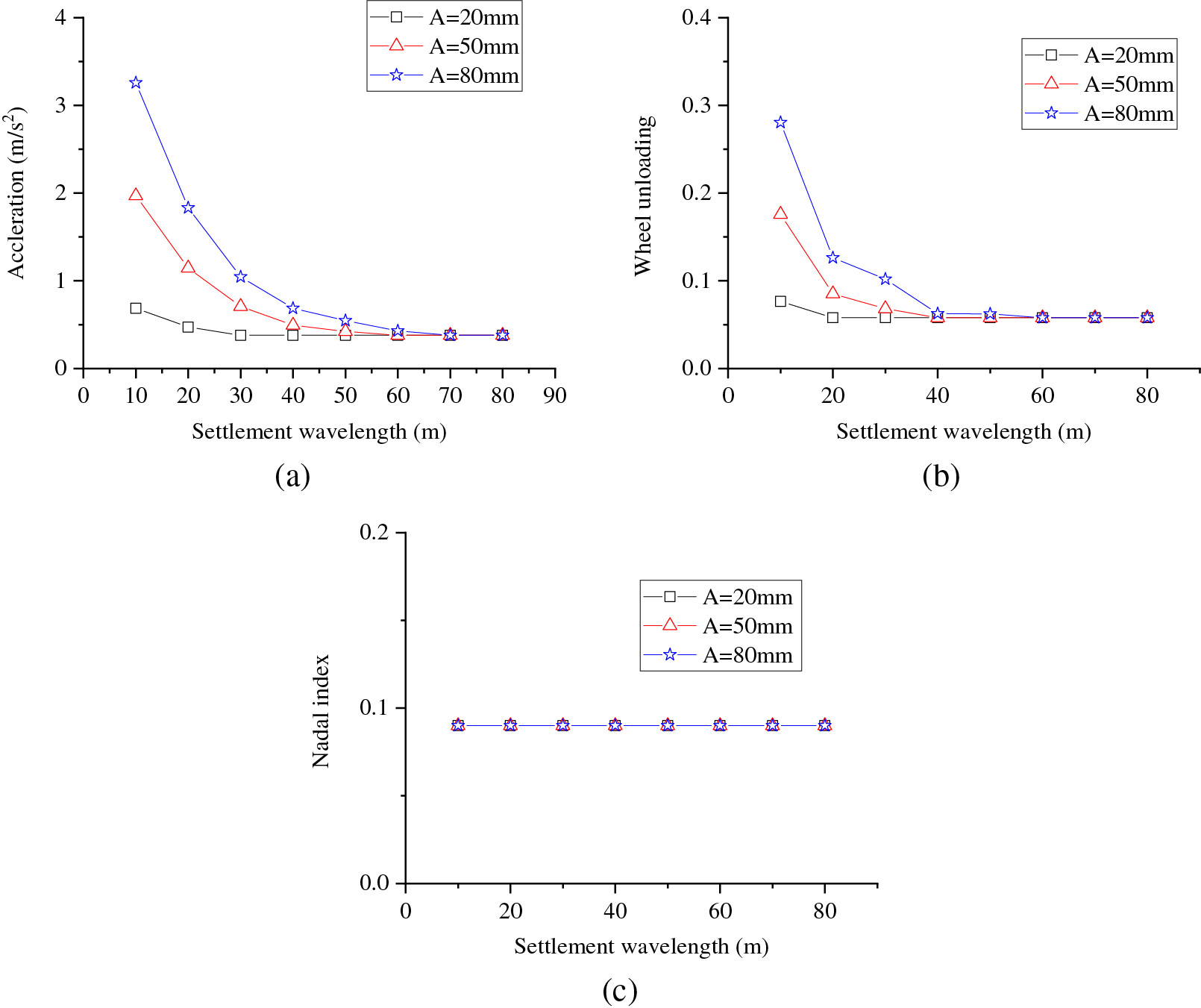
Figure 13: Influence of tunnel settlement wavelength on running performance: (a) acceleration; (b) wheel unloading; (c) Nadal index
Vehicle speed significantly influences the responses. We calculated vehicle responses for settlements with amplitudes of 40 mm and wavelengths of 40, 50, and 60 m, respectively, under conditions of 80–110 km/h. The results of these calculations are illustrated in Fig. 14.
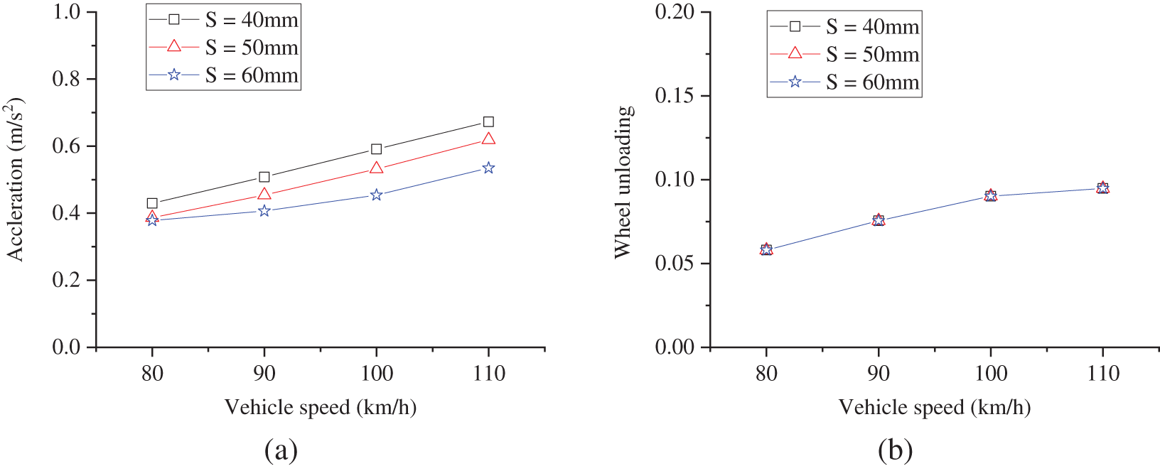
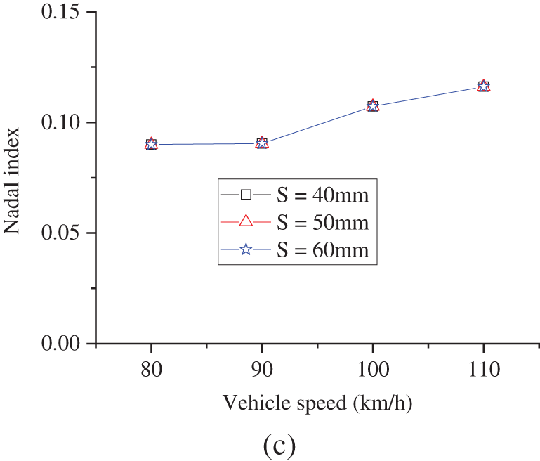
Figure 14: Influence of vehicle speed on running performance: (a) acceleration; (b) wheel unloading; (c) Nadal index
To more effectively assess the actual settlement of subway lines, we calculated the vehicle running performance under various conditions, focusing primarily on the car body acceleration, wheel unloading, and Nadal index. The respective limits for car body acceleration, wheel unloading, and the Nadal index are 1.3 m/s², 0.6, and 0.8.
The outcomes of these calculations are presented in Fig. 15. Among all evaluated responses, the acceleration of the car body proved to be the most sensitive to parameter alterations.
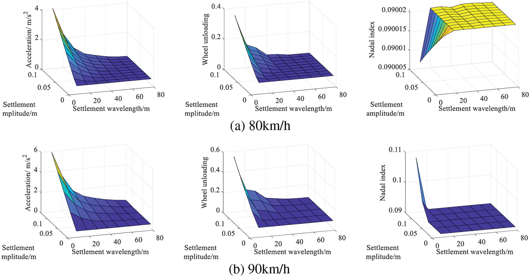
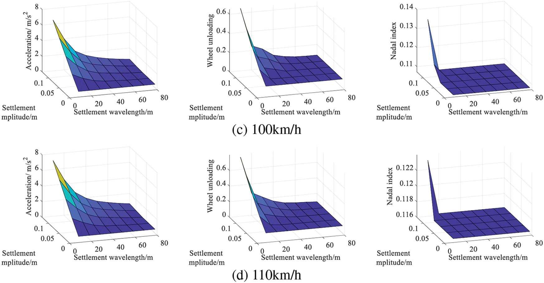
Figure 15: Running performance with various parameters
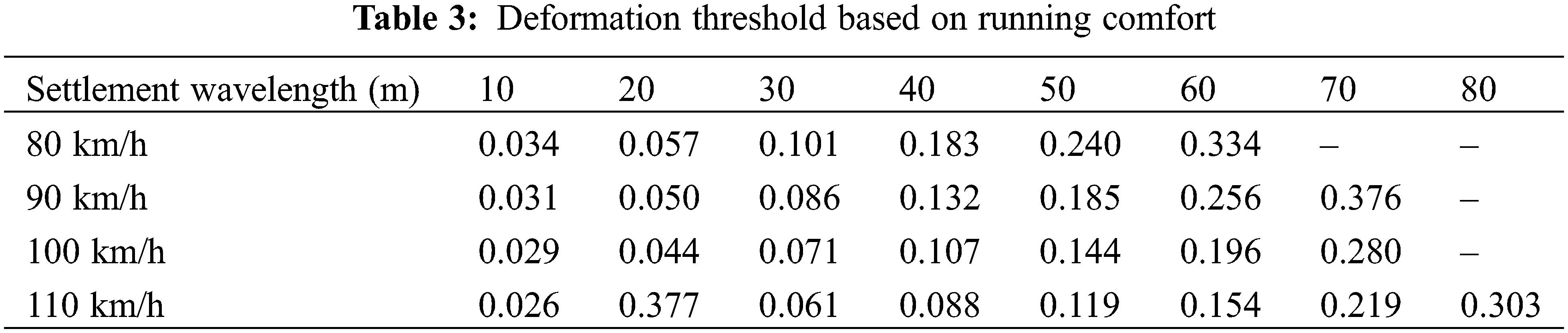
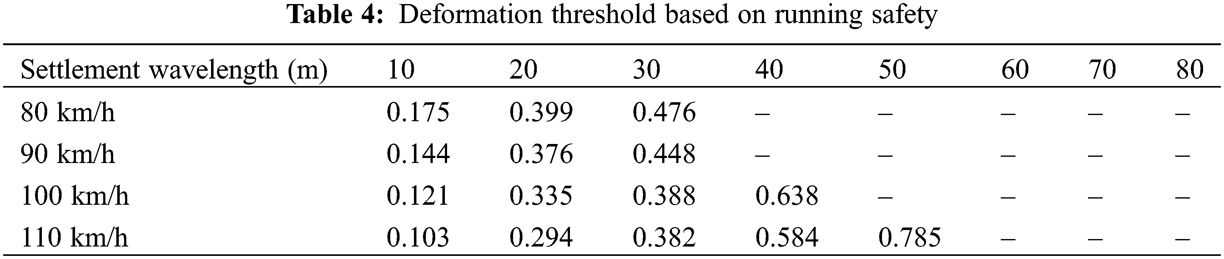
The findings presented in Fig. 15 were organized to ascertain the settlement thresholds based on both running comfort and safety. These results are documented in Tables 3 and 4. By referencing these tables, one can determine the threshold values for settlement amplitude corresponding to various settlement wavelengths and vehicle speeds. It is apparent that the running safety threshold is higher than the comfort threshold, a result that aligns well with practical scenarios.
During subway tunnel construction and operation, soil settlement can lead to shield segment sinking. This condition often results in a series of problems, such as segment damage and rail deformation, negatively impacting the comfort and safety of vehicle operation. This study aimed to investigate the effects of tunnel settlement on vehicle running performance. To this end, an analytical mapping model was established to represent the relationship between tunnel settlement and rail deformation. The model’s accuracy was then validated using a case study. Moreover, a cyclic vehicle-track-tunnel coupled system was developed, its accuracy confirmed via literature comparison. The analysis of the vehicle’s dynamic response while traversing the settling area was carried out, followed by a discussion on the influence of different parameters on running performance. The main conclusions are as follows:
(1) The analytical mapping model accurately calculates the rail geometry deformation due to tunnel settlement. Compared to the Finite Element (FE) model, this model simplifies the calculations.
(2) Tunnel settlement affects driving comfort more significantly than it does running safety.
(3) Both the settlement wavelength and amplitude significantly impact the vehicle’s running performance. Increasing the settlement wavelength improves vehicle performance, whereas augmenting the settlement amplitude impairs it.
(4) Through the developed threshold table, rapid assessment of tunnel settlement is possible. The running safety threshold is higher than the comfort threshold.
(5) It is important to note that this study primarily focuses on the impact of track geometric deformation, caused by settlement, on the dynamic running performance. It does not take into account instances of segment breakage.
(6) Shield deformation has an impact on the performance of vehicle operation, and under the action of vehicle loads, it may further deteriorate the deformation of shield tunneling. This is mutual and will be a research focus of future attention.
Acknowledgement: None.
Funding Statement: This study was funded by the Scientific Research Startup Foundation of Fujian University of Technology (GY-Z21067 and GY-Z21026).
Author Contributions: The authors confirm contribution to the paper as follows: study conception and design: Gang Niu and Guangwei Zhang; data collection: Guangwei Zhang and Zhaoyang Jin; analysis and interpretation of results: Wei Zhang and Xiang Liu; draft manuscript preparation: Gang Niu, Xiang Liu and Wei Zhang. All authors reviewed the results and approved the final version of the manuscript.
Availability of Data and Materials: The data that support the findings of this study are available from the corresponding author upon reasonable request.
Conflicts of Interest: The authors declare that they have no conflicts of interest to report regarding the present study.
References
1. Guo, J., Liu, G. (2023). Experimental study on the soil-structure responses induced by tunnelling in limited space. Applied Sciences, 13(12), 7000. https://doi.org/10.3390/app13127000 [Google Scholar] [CrossRef]
2. Jiang, Y., Li, Y., Yao, A., Gao, X., Li, H. (2023). Soil deformation investigation of a piled-raft foundation pit under-crossed by a super-large diameter shield tunnel. Applied Sciences, 13(9), 5774. https://doi.org/10.3390/app13095774 [Google Scholar] [CrossRef]
3. Oh, D. W., Kong, S. M., Kim, S. B., Lee, Y. J. (2023). Prediction and analysis of axial stress of piles for piled raft due to adjacent tunneling using explainable AI. Applied Sciences, 13(10), 6074. https://doi.org/10.3390/app13106074 [Google Scholar] [CrossRef]
4. Sun, L., Zhao, J., Qin, W., Hou, D., Wang, X. (2023). Dynamic response analysis of soil around curve section tunnel under train vibration load. Applied Sciences, 13(14), 8013. https://doi.org/10.3390/app13148013 [Google Scholar] [CrossRef]
5. Yang, P., Yong, W., Li, C., Peng, K., Wei, W. et al. (2023). Hybrid random forest-based models for earth pressure balance tunneling-induced ground settlement prediction. Applied Sciences, 13(4), 2574. https://doi.org/10.3390/app13042574 [Google Scholar] [CrossRef]
6. Zhang, C., Zhao, Y., Zhang, Z., Zhu, B. (2021). Case study of underground shield tunnels in interchange piles foundation underpinning construction. Applied Sciences, 11(4), 1611. https://doi.org/10.3390/app11041611 [Google Scholar] [CrossRef]
7. Guo, X., Wang, Z., Geng, P., Chen, C., Zhang, J. (2021). Ground surface settlement response to subway station construction activities using pile–beam–arch method. Tunnelling and Underground Space Technology, 108(8), 103729. https://doi.org/10.1016/j.tust.2020.103729 [Google Scholar] [CrossRef]
8. Topal, C., Mahmutoğlu, Y. (2021). Assessment of surface settlement induced by tunnel excavations for the esenler-başakşehir (Istanbul, Turkey) subway line. Environmental Earth Sciences, 80(5), 188. https://doi.org/10.1007/s12665-021-09509-6 [Google Scholar] [CrossRef]
9. Bai, Q., Zhang, Y., Zhao, W., Jia, P., Li, S. et al. (2023). Construction of subway station using the small pipe roof-beam method: A case study of Shifu Road station in Shenyang. Tunnelling and Underground Space Technology, 135(5), 105000. https://doi.org/10.1016/j.tust.2023.105000 [Google Scholar] [CrossRef]
10. Luo, C., Cheng, Y., Bai, Z., Shen, T., Wu, X. Y. et al. (2021). Study on settlement and deformation of urban viaduct caused by subway station construction under complicated conditions. Advances in Civil Engineering, 2021(5), 1–16. https://doi.org/10.1155/2021/6625429 [Google Scholar] [CrossRef]
11. Liu, X., Jiang, L., Lai, Z., Xiang, P., Chen, Y. (2020). Sensitivity and dynamic analysis of train-bridge coupled system with multiple random factors. Engineering Structures, 221(7), 111083. https://doi.org/10.1016/j.engstruct.2020.111083 [Google Scholar] [CrossRef]
12. Lai, Z., Jiang, L., Zhou, W., Yu, J., Zhang, Y. et al. (2022). Lateral girder displacement effect on the safety and comfortability of the high-speed rail train operation. Vehicle System Dynamics, 60(9), 3215–3239. https://doi.org/10.1080/00423114.2021.1942507 [Google Scholar] [CrossRef]
13. Xiang, P., Huang, W., Jiang, L., Lu, D., Liu, X. et al. (2021). Investigations on the influence of prestressed concrete creep on train-track-bridge system. Construction and Building Materials, 293, 123504. https://doi.org/10.1016/j.conbuildmat.2021.123504 [Google Scholar] [CrossRef]
14. Zhong, H., Yang, M. (2017). Dynamic effect of foundation settlement on bridge-vehicle interaction. Engineering Structures, 135, 149–160. https://doi.org/10.1016/j.engstruct.2017.01.006 [Google Scholar] [CrossRef]
15. Guo, Y., Sun, Q., Sun, Y. (2023). Dynamic evaluation of vehicle-slab track system under differential subgrade settlement in China’s high-speed railway. Soil Dynamics and Earthquake Engineering, 164(4), 107628. https://doi.org/10.1016/j.soildyn.2022.107628 [Google Scholar] [CrossRef]
16. Sun, Y., Guo, Y., Chen, Z., Zhai, W. (2018). Effect of differential ballast settlement on dynamic response of vehicle-track coupled systems. International Journal of Structural Stability and Dynamics, 18(6), 1850091. https://doi.org/10.1142/S0219455418500918 [Google Scholar] [CrossRef]
17. Zeng, Q., Dimitrakopoulos, E. G. (2018). Vehicle-bridge interaction analysis modeling derailment during earthquakes. Nonlinear Dynamics, 93(1), 2315–2337. https://doi.org/10.1007/s11071-018-4327-6 [Google Scholar] [CrossRef]
18. Zhou, T., Jiang, L., Xiang, P., Liu, X. (2023). Effects of near-fault pulse-type ground motion on train-track–bridge coupled system with nonlinear supports. Nonlinear Dynamics, 111(7), 6213–6238. https://doi.org/10.1007/s11071-022-08156-1 [Google Scholar] [CrossRef]
19. Zhou, T., Jiang, L., Xiang, P., Lai, Z., Zhang, Y. et al. (2022). Effects of near-fault pulse-type ground motions on high-speed railway simply supported bridge and pulse parameter analysis. Bulletin of Earthquake Engineering, 20(149–155), 1–26. https://doi.org/10.1007/s10518-022-01438-4 [Google Scholar] [CrossRef]
20. Chen, Y., Jiang, Y., Li, C., Liu, X., Li, J. (2021). An efficent computing strategy based on the unconditionally stable explicit algorithm for the nonlinear train-track-bridge system under an earthquake. Soil Dynamics and Earthquake Engineering, 145, 106718. https://doi.org/10.1016/j.soildyn.2021.106718 [Google Scholar] [CrossRef]
21. Xia, Z., Zhu, L., Wu, F. (2021). Analysis of metro vehicle-track coupling vibration responses and optimization of track structure parameters. Noise and Vibration Control, 41(2), 168–173+189 (In Chinese). [Google Scholar]
Cite This Article
 Copyright © 2024 The Author(s). Published by Tech Science Press.
This work is licensed under a Creative Commons Attribution 4.0 International License , which permits unrestricted use, distribution, and reproduction in any medium, provided the original work is properly cited.
 Downloads
 Citation Tools