
 Submit a Paper
 Propose a Special lssue
 Open Access
ARTICLE

Investigation of FRP and SFRC Technologies for Efficient Tunnel Reinforcement Using the Cohesive Zone Model
1 China Communications Construction Investment Development Co., Ltd., Fuzhou, 350000, China
2 Rail Transit Branch of China Communications Construction Co., Ltd., Beijing, 101317, China
3 School of Civil Engineering, Fujian University of Technology, Fuzhou, 350118, China
* Corresponding Author: Wei Zhang. Email:
Structural Durability & Health Monitoring 2024, 18(2), 161-179. https://doi.org/10.32604/sdhm.2023.044580
Received 03 August 2023; Accepted 24 October 2023; Issue published 22 March 2024
 View Full Text
 Download PDF
Abstract
Amid urbanization and the continuous expansion of transportation networks, the necessity for tunnel construction and maintenance has become paramount. Addressing this need requires the investigation of efficient, economical, and robust tunnel reinforcement techniques. This paper explores fiber reinforced polymer (FRP) and steel fiber reinforced concrete (SFRC) technologies, which have emerged as viable solutions for enhancing tunnel structures. FRP is celebrated for its lightweight and high-strength attributes, effectively augmenting load-bearing capacity and seismic resistance, while SFRC’s notable crack resistance and longevity potentially enhance the performance of tunnel segments. Nonetheless, current research predominantly focuses on experimental analysis, lacking comprehensive theoretical models. To bridge this gap, the cohesive zone model (CZM), which utilizes cohesive elements to characterize the potential fracture surfaces of concrete/SFRC, the rebar-concrete interface, and the FRP-concrete interface, was employed. A modeling approach was subsequently proposed to construct a tunnel segment model reinforced with either SFRC or FRP. Moreover, the corresponding mixed-mode constitutive models, considering interfacial friction, were integrated into the proposed model. Experimental validation and numerical simulations corroborated the accuracy of the proposed model. Additionally, this study examined the reinforcement design of tunnel segments. Through a numerical evaluation, the effectiveness of innovative reinforcement schemes, such as substituting concrete with SFRC and externally bonding FRP sheets, was assessed utilizing a case study from the Fuzhou Metro Shield Tunnel Construction Project.Graphic Abstract
Keywords
Nomenclature
| FRP | Fiber reinforced polymer |
| SFRC | Steel fiber reinforced concrete |
| CZM | Cohesive zone model |
| CMOD | Crack mouth opening displacement |
In recent years, urbanization and the expansion of transportation networks have created higher demands for the construction and maintenance of urban tunnels. When confronted with tunnel structural deterioration and damage, traditional maintenance methods often require large-scale shutdowns and construction, which are inconvenient and consume significant resources. Therefore, the development of efficient, economical, and sustainable tunnel structure strengthening technologies is crucial for extending the service life of tunnel structures and ensuring the safety of urban transportation.
With the advancement of fiber-reinforced polymer (FRP) and steel fiber-reinforced concrete (SFRC) technologies, these two innovative materials have become focal points in research on tunnel structure reinforcement. FRP, characterized by its lightweight and high-strength properties, demonstrates exceptional tensile performance and durability, effectively enhancing the load-carrying capacity (the deboning of the FRP-concrete interface can be categorized into single-mode [1–5] and mixed-mode [6–9]), structure durability [10,11], and seismic resistance [12–15] of tunnels. SFRC has also attracted substantial attention because of its remarkable crack resistance [16–18], erosion resistance [19], and Strength improvement capability [19–24]. Through the application of SFRC or FRP materials to reinforce tunnel segments, it is feasible not only to augment the tunnel structure’s seismic and load-carrying capacities, but also to extend the tunnel’s service life and mitigate maintenance costs, thereby providing reliable support for the safe operation of urban tunnels.
Researchers have proposed various strengthening methods to reinforce or repair tunnels, including steel plate reinforcement [25–27], fiber-reinforced polymer (FRP) reinforcement [28–33], and SFRC reinforcement [34–37], and corresponding experimental studies have been conducted for each. However, current research on tunnel segment reinforcement primarily relies on experimental analysis and lacks intricate models and theories to provide a mechanistic understanding of the entire fracture process. In the domain of tunnel segment reinforcement, although experimental studies may provide insights for practical engineering applications, the constraints of experimental outcomes and the variability in actual construction conditions may hinder a thorough comprehension of the underlying reinforcement mechanisms. Consequently, a more comprehensive understanding of the fracture process in reinforced segments requires sophisticated numerical simulations and theoretical models.
The cohesive zone model (CZM) is a computational mechanics model employed to simulate material interface fracture and crack propagation. It has been extensively used in various engineering disciplines, including fracture of concrete [38–41], failure of FRP-concrete interface [42,43], and so on. In addition, the CZM l has been used in tunnel engineering to simulate the interaction between tunnel segments [44,45] and the fracture behavior of the tunnel lining [46]. However, the CZM has mainly been applied to large-scale macromodels in the field of tunnel engineering. There is still limited research using the CZM to study the specific structural fractures and failures of segmental tunnels.
In this study, a CZM for simulating tunnel segments was formulated based on cohesive elements. These elements were employed to simulate the potential fracture surfaces of the concrete/SFRC, rebar-concrete interface, and FRP-concrete interfaces. The corresponding mixed-mode constitutive models that account for the interfacial friction effect were incorporated into the established model. Typical load-capacity experiments were conducted to validate the proposed model. Subsequently, a series of numerical experiments were conducted to evaluate the enhancement effects of SFRC or FRP on the tunnel segment, drawing on the Fuzhou Metro Shield Tunnel Construction Project.
2 Establishment of the FRP-Strengthened Reinforced Concrete Structures
In order to better simulate the fracture behavior and mechanical response of the FRP-strengthened tunnel segment, the fracture failure of concrete and SFRC, the slip between the steel reinforcement and concrete, and mechanical behavior at the FRP-concrete interface must be accurately represented in the model. Therefore, based on a series of preliminary studies conducted earlier, this section integrates these key constitutive models and implements them in the model. A brief description of each key constitutive model is as follows.
2.1 Modeling Method Based on Cohesive Elements
The modeling method derived from previous studies [9,41] was employed to construct an FRP-strengthened reinforced concrete structure, as illustrated in Fig. 1. In this model, solid elements are utilized to represent the concrete and steel rebars, whereas beam elements are employed to represent the FRP plates. Additionally, cohesive elements are implemented to characterize the mechanical behavior of potential fracture surfaces within the concrete as well as the bond-slip behavior of the concrete-rebar and concrete-FRP interfaces. The procedure for establishing the model is as follows:
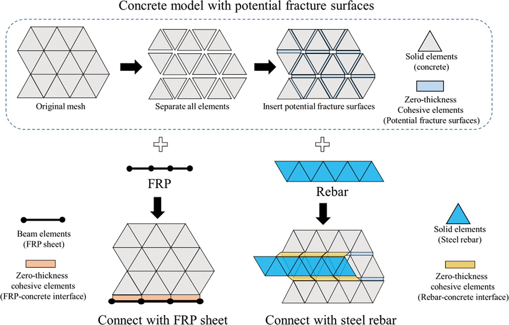
Figure 1: Modeling method of FRP-strengthened reinforced concrete structure
1. The concrete substrate model is constructed, potential fracture surfaces are identified, and the regions where the steel rebar is embedded and the FRP is bonded are labeled.
2. The solid elements are integrated to symbolize the steel rebar and the concrete-rebar interface.
3. The beam elements are incorporated to symbolize the FRP plates and the FRP-concrete interface
2.2 Mixed-Mode Constitutive Models for Different Components
2.2.1 Concrete/SFRC Potential Fracture Surfaces
(1) Plain concrete
The previously proposed mixed-mode constitutive model [9,41] was used to characterize the concrete potential fracture surfaces. The distinctive characteristic of this constitutive model lies in its meticulous consideration of the interfacial friction stress, which is built upon the foundation of the bilinear damage model, as shown in Fig. 2. Stress can be expressed as follows:
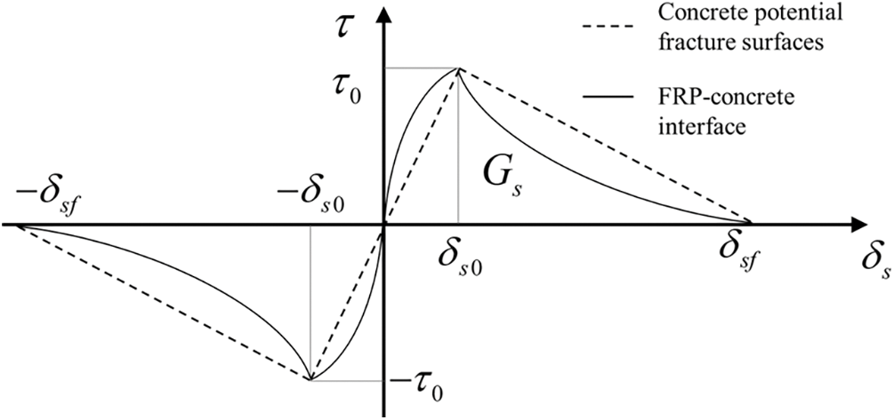
Figure 2: Two types of interfacial damage modes (Tangential direction)
where
In particular, as shown in Fig. 3, the friction stress
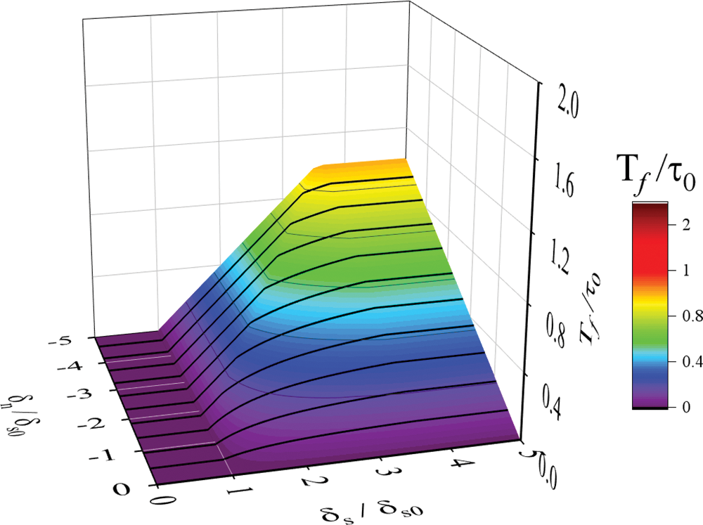
Figure 3: Friction stress under different normal and tangential displacements
1) Interface not sliding condition
The maximum friction stress
where
Thus, the friction stress can be given as follows:
where
2) Interface sliding condition
When slip occurs, the friction stress is equal to the maximum friction stress, which can be expressed as follows:
where
(2) SFRC
The potential fracture surface constitutive model bears resembles that of concrete, but it incorporates the bridging effect. As illustrated in Fig. 4a, the bridging effect of the SFRC is depicted as a component of the interfacial interaction stresses, and the corresponding stress–displacement relationship (for hooked-end fibers) is simplified, as shown in Fig. 4b [24]. This relationship is expressed as follows:
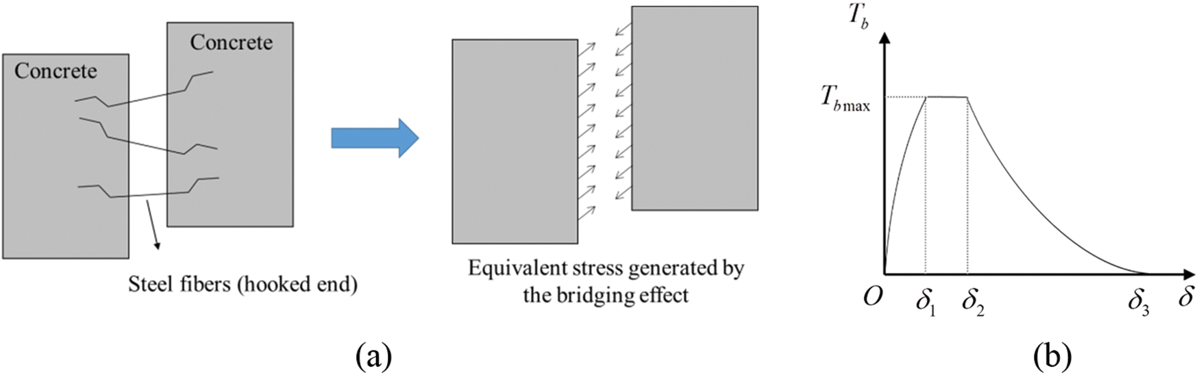
Figure 4: Equivalent representation of the bridging effect: (a) equivalent stress; (b) stress-displacement relation
where
Based on the above, by orthogonal decomposition of the bridging stress in the normal and tangential directions, the stress expression for the SFRC potential fracture surfaces can be expressed as follows:
The mixed-mode constitutive model of the FRP-concrete interface [9,41] is similar to the concrete potential fracture surface, as shown in Fig. 2. However, in this constitutive model, the softening segment of the stress–displacement curve transitioned from linear to exponential decay, as shown in Fig. 2. The stress expressions are identical to Eqs. (1) and (2). The damage coefficient can be calculated as follows:
2.2.3 Rebar–Concrete Interface
The concrete-rebar interface also adopts the mixed-mode constitutive model [9,41]. In the tangential direction, this constitutive model adopts the bond-slip relationship curve recommended by CEB-FIP. In the normal direction, the same bilinear damage constitutive model is used for the potential fracture surfaces of the concrete. Moreover, the normal separation at the interface weakens the tangential bonding relationship. The bond-slip relationship of the interface recommended by CEB-FIP [47] is expressed as follows:
where
For the interface between the ribbed rebar and concrete, the weakening effect of the normal separation on the tangential bond-slip behavior is considered, as shown in Fig. 5. Thus, a weakening parameter is defined based on the degree of normal separation and can be expressed as follows:
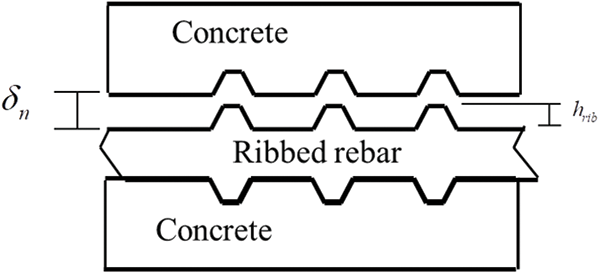
Figure 5: Normal separation of the rebar–concrete interface
Thus, considering the weakening effect caused by normal separation, the modified bond stress
2.3 Validation of the Proposed Model
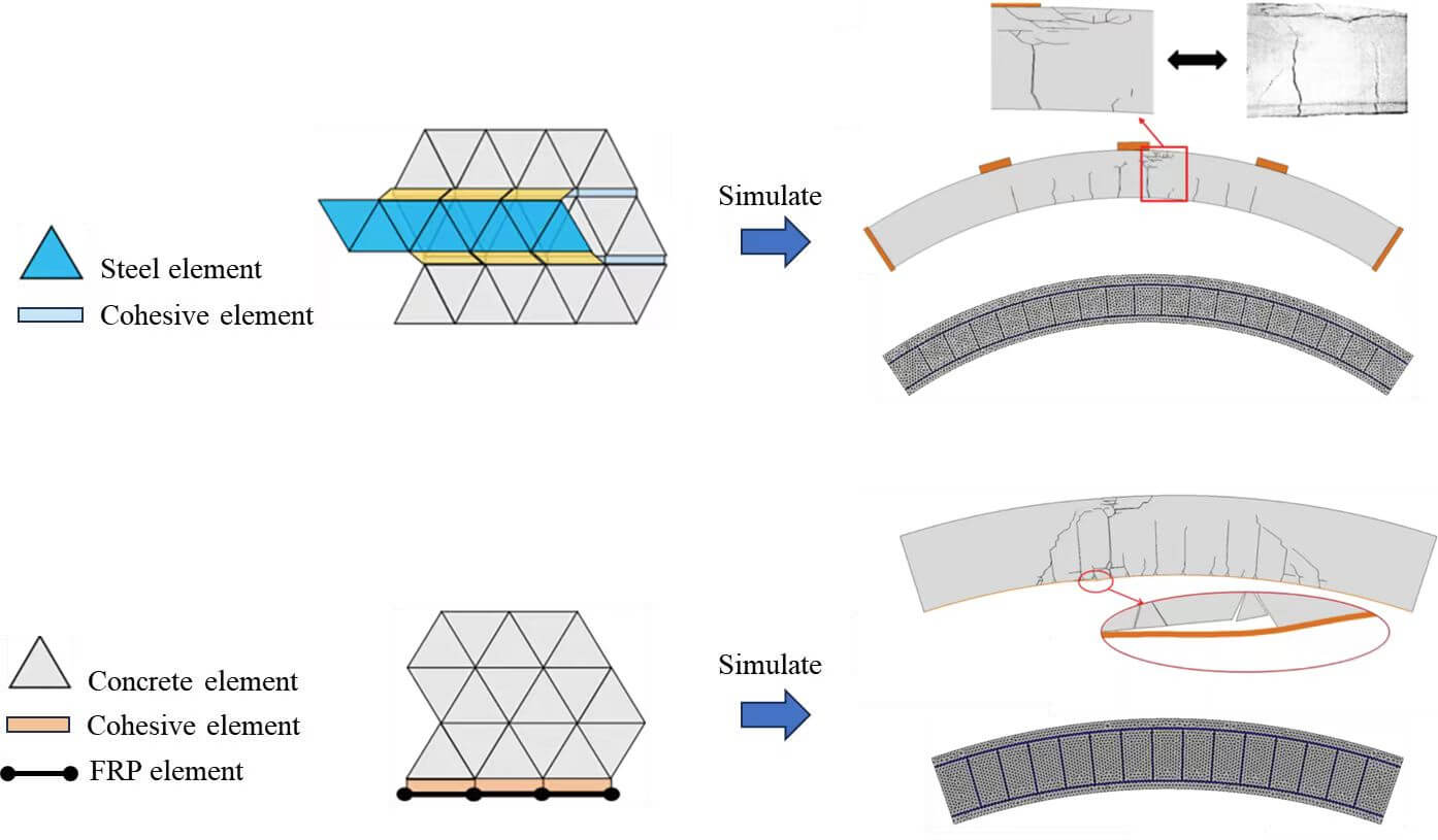
An experimental case involving an RC (Reinforced Concrete) segment in a subway tunnel was selected [25]. The test schedule and specimen sizes are depicted in Fig. 5. The specimen was a full-scale segment manufactured in a factory. The outer and inner diameters of the tunnel segments were 3000 and 2700 mm, respectively. The width and central angle of the tunnel segments were 1200 mm and 67.5°, respectively. The segments were constructed using the C50 and HRB400 reinforcements. The upper part of the tunnel segment was reinforced with eight steel-ribbed rebars, each with a diameter of 18 mm, and the lower part was equipped with eight steel-ribbed rebars, each with a diameter of 16 mm. In addition, 72 plain rebars with a diameter of 8 mm were designed for each segment.
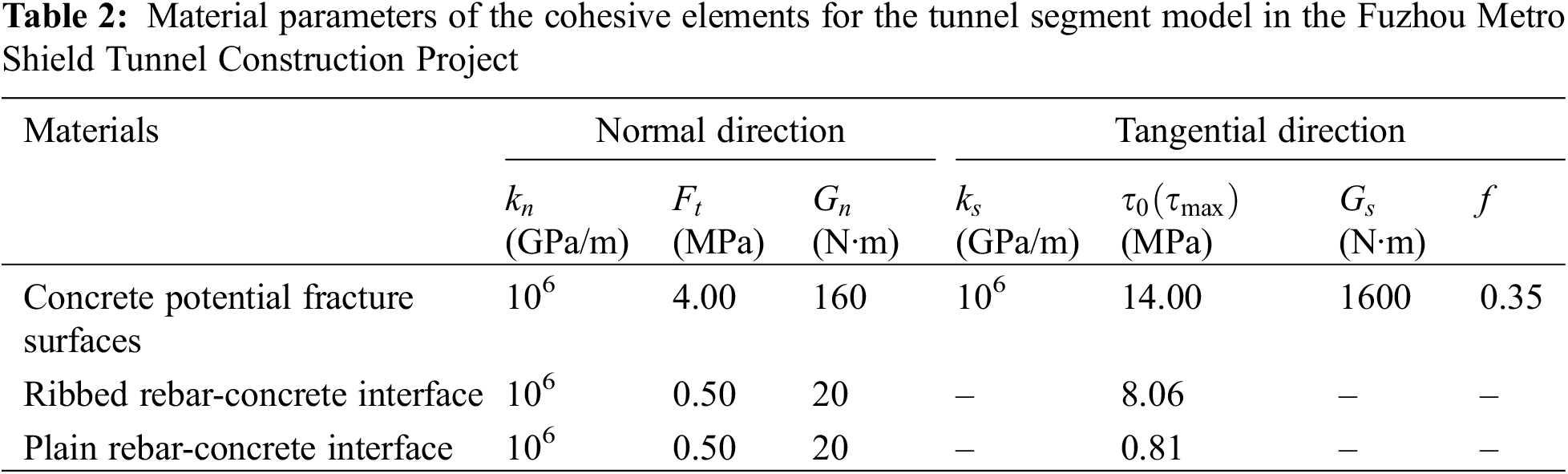
As shown in Figs. 6a and 6b, two sets of experimental results were selected to validate the accuracy of the model, and the corresponding tunnel segments are denoted as Pzw1 and Pzw2. Tunnel segment Pzw1 was supported by a simple support, providing vertical reaction forces only. On the other hand, for tunnel segment Pzw2, double-hinged support was applied at both ends, which provide axial constraints at the ends to reflect the actual loading conditions. Three equivalent loads were applied simultaneously, as shown in the figure.
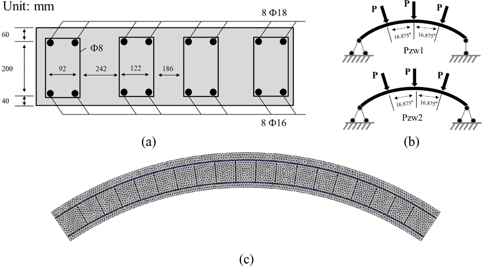
Figure 6: Geometric dimensions, loading conditions, and FE model of the tunnel segment: (a) design of the cross section; (b) loading conditions; and (c) FE model
The FE model of the tunnel segment is depicted in Fig. 6c. It consisted of a total of 19,500 nodes, 6,200 triangular elements, and 11,000 cohesive elements. The concrete and steel rebars are represented using the solid element CPS3, whereas the potential fracture surfaces of the concrete and concrete-rebar interfaces are represented using the cohesive element COH2D4. For each steel rebar in the model, the width was taken as the radius R of the rebar, and the out-of-plane thickness was taken as
The model was based on the EXPLICIT solver in the commercial finite element software ABAQUS [48]. This was solved using a quasistatic approach. All proposed constitutive models were integrated into the FE software through secondary development [9,41] using the FORTRAN programming language (user subroutine VUMAT).
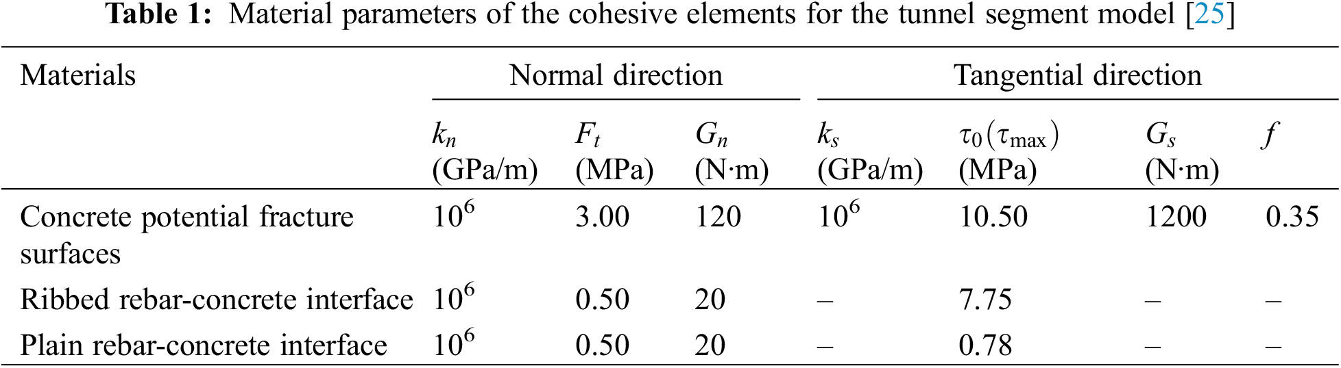
According to the material parameters provided in [25], repeat trials, and related studies on the CZM model [38–41], the material parameters for the cohesive elements are listed in Table 1. In addition, the elastic modulus E and Poisson’s ratio v of the concrete solid element are 34.5 GPa and 0.22, respectively. The elastic modulus E, Poisson’s ratio v, and yield strength
The calculated load–deflection curves of the tunnel segment are shown in Fig. 7. For segment Pzw1, the ultimate bearing capacity is approximately 190 kN, and the specimen under the simple support boundary condition exhibits a relatively long plastic segment. For segment Pzw2, its ultimate bearing capacity is approximately 1000 kN, which is about five times that of Pzw1, owing to the axial constraints on both sides. The corresponding experimental results are also shown in Fig. 7. By comparing the simulated and experimental results, it can be observed that the load-deflection curve obtained from the simulation matches, both in form and magnitude, the experimental results. This indicates that the numerical model established in this study can effectively reflect the macroscopic mechanical behavior of the shield tunnel segments.
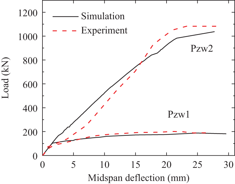
Figure 7: Load–deflection curves of the tunnel segments
The crack distributions in the tunnel segments obtained from the simulation results are shown in Fig. 8 for comparison with the experimental results. The cracks in the model were represented by deleting the cohesive elements whose damage factor reached one. For Pjw1, the ultimate failure mode shows tension cracking at the bottom, with cracks propagating upward, and compression failure causing lateral cracks at the top. As for Pjw2, although the failure mode is similar to that for Pjw1, the presence of axial constraints at both ends significantly reduces the number and extent of the cracks. A comparison in the figure demonstrates that the established model effectively captures the fracture patterns of the tunnel segments. In conclusion, the use of this model for analyzing the stress and fracture performances of tunnel segments is feasible.
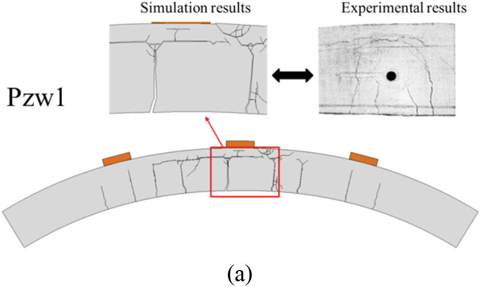
Figure 8: Crack distribution of the tunnel segments
3 Reinforcement Design Optimization of Shield Tunneling Segments
Currently, to meet the requirements of the Fuzhou Metro Shield Tunnel Construction Project, there is a need to analyze and evaluate new reinforcement schemes for shield tunnel segments. Two main novel reinforcement schemes were considered: Replacing conventional concrete with SFRC and external bonding of FRP sheets at the bottom of the segments.
Therefore, this section presents numerical simulations and evaluations of a representative segment. Simulations were performed for both the original prototype segment and the segment using the two new reinforcement schemes under simple-support and hinged-support boundary conditions. The aim was to analyze and assess the performance enhancement of the two novel reinforcement schemes with respect to the behavior of the tunnel segment.
3.1 Design Information of the Shield Tunneling Segment
The geometry and loading scheme of the tunnel segment are illustrated in Fig. 9. The cross section and configuration of the analyzed tunnel segment (simplified) are shown in Figs. 9a–9b. The outer radius of the segment was 4150 mm, the inner radius was 3750 mm, and the thickness was 1800 mm. The central angle of each segment was 38°. The segment was constructed using C55 high-strength concrete and HRB400 steel reinforcement. Fifteen ribbed steel rebars with diameters of 20 mm were placed in the upper and lower parts of the segment. Additionally, 98 plain round steel rebars with a diameter of 8 mm were used as stirrups. The thickness of the steel-reinforcement protective layer for each segment was 50 mm.
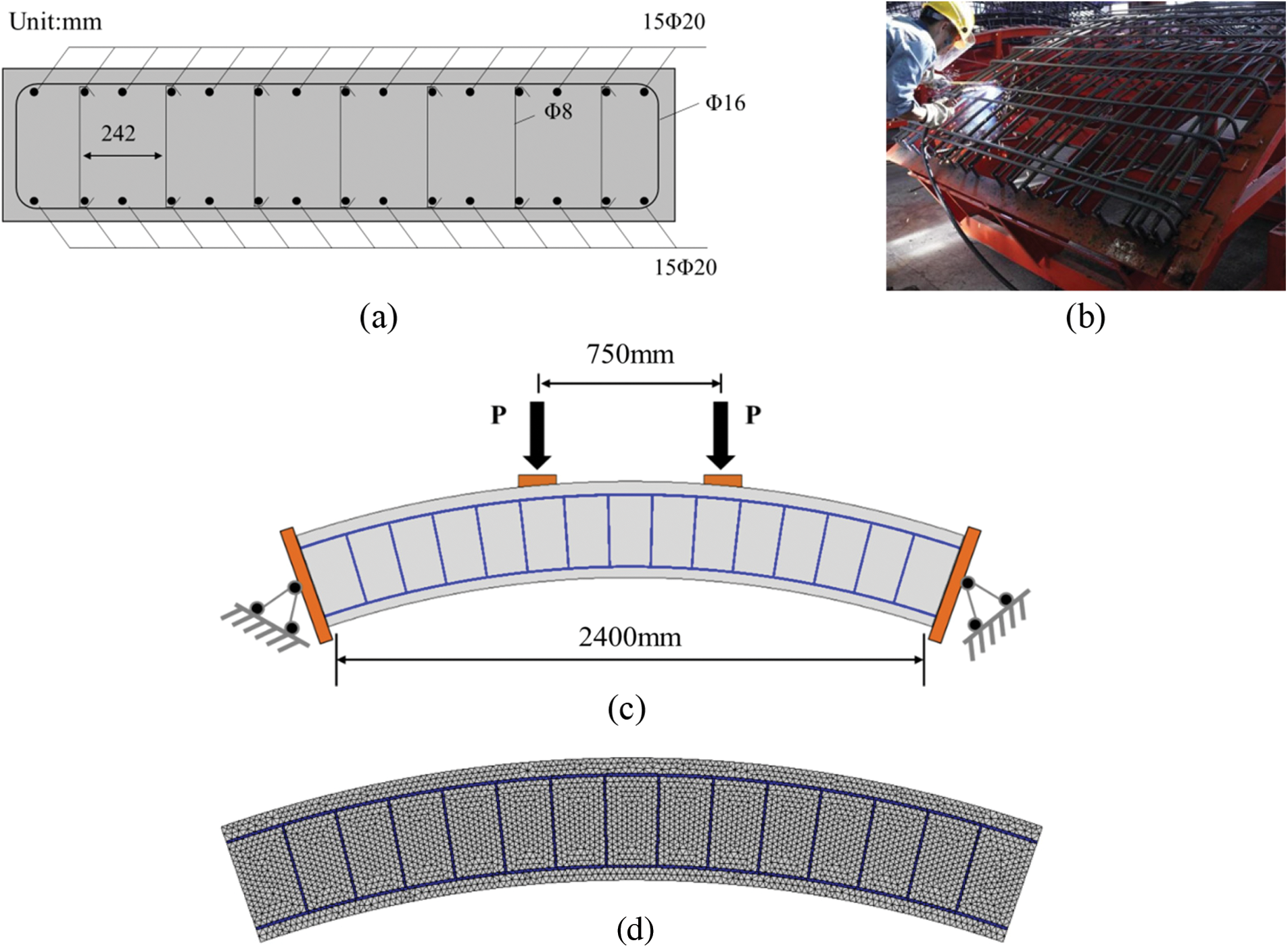
Figure 9: Geometry and loading scheme of the typical tunnel segment: (a) geometry information; (b) internal reinforcement of the tunnel segment; (c) loading scheme (double-hinged support); and (d) FE model
In Section 3.1, the experiment used a loading method in which three loading points were synchronized to apply the loads. However, this method is only suitable for pipes with large central angles (67.5°). In this section, the central angle of the pipe piece is only 38°. Therefore, using two loading points is sufficient to reflect the influence of the external pressure. For the convenience of assessment, the four-point bending (FPB) loading method was adopted, as shown in Fig. 9c. The corresponding FE model of the segment is shown in Fig. 9c, with 21,000 nodes, 6,700 triangular elements, and 10,000 cohesive elements.
According to the material parameters provided by the manufacturer, repeat trials, and related studies on the CZM model [38–41], the material parameters of the cohesive elements are listed in Table 2. In addition, the elastic modulus E and Poisson’s ratio v of the concrete solid element are 34.5 GPa and 0.22, respectively. The elastic modulus E, Poisson’s ratio v, and yield strength fy of the steel rebar were 200 GPa, 0.3, and 400 MPa, respectively.
The bearing capacities of the segments under different boundary conditions are shown in Fig. 10a. Under the simple-support condition, the ultimate bearing capacity was approximately 900 kN. The failure mode of the tunnel segment was plastic, and its fracture pattern exhibited cracking at the bottom, extending upward in the pure bending region, followed by a compression crash at the top, as shown in Fig. 10b. Under the double-hinged support, the axial constraint significantly enhanced the ultimate bearing capacity to approximately 5500 kN, which was approximately six times higher than that obtained under simple support conditions. The failure mode under the double-hinged support was shear failure, and the extent of cracking in the pure bending region was significantly suppressed, as shown in Figs. 10c and 10d.
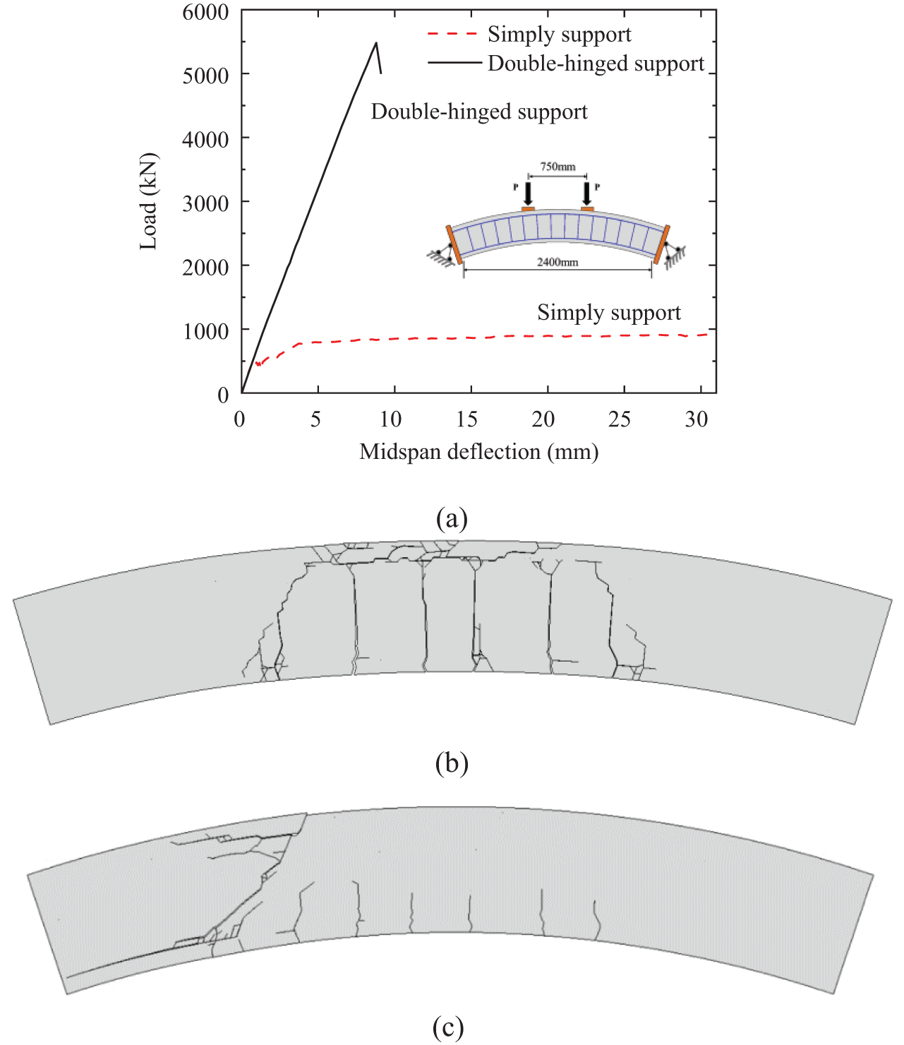
Figure 10: Simulation results of the tunnel segments: (a) load-deflection curves under different boundary conditions; (b) fracture pattern of the segment under simply support condition; (c) fracture pattern of the segment under double-hinged support condition
3.2 Reinforcement Design and Anlysis
3.2.1 Segment Strengthen by Replacing Concrete with SFRC
Steel fiber-reinforced concrete (SFRC) has gradually been used in engineering projects. Because of the addition of steel fibers, SFRC exhibits excellent crack resistance, impact resistance, and durability, effectively improving the mechanical properties and performance stability of concrete. Consequently, SFRC has become an essential construction material and is increasingly used in various engineering projects.
In this study, hooked-end fibers were chosen for use as internal reinforcements in SFRC. To obtain the mechanical behavior of the SFRC, as shown in Fig. 11a, a series of three-point bending tests [24] were carried out. As shown in Fig. 11b, the geometry of the hooked-end fiber was as follows: length
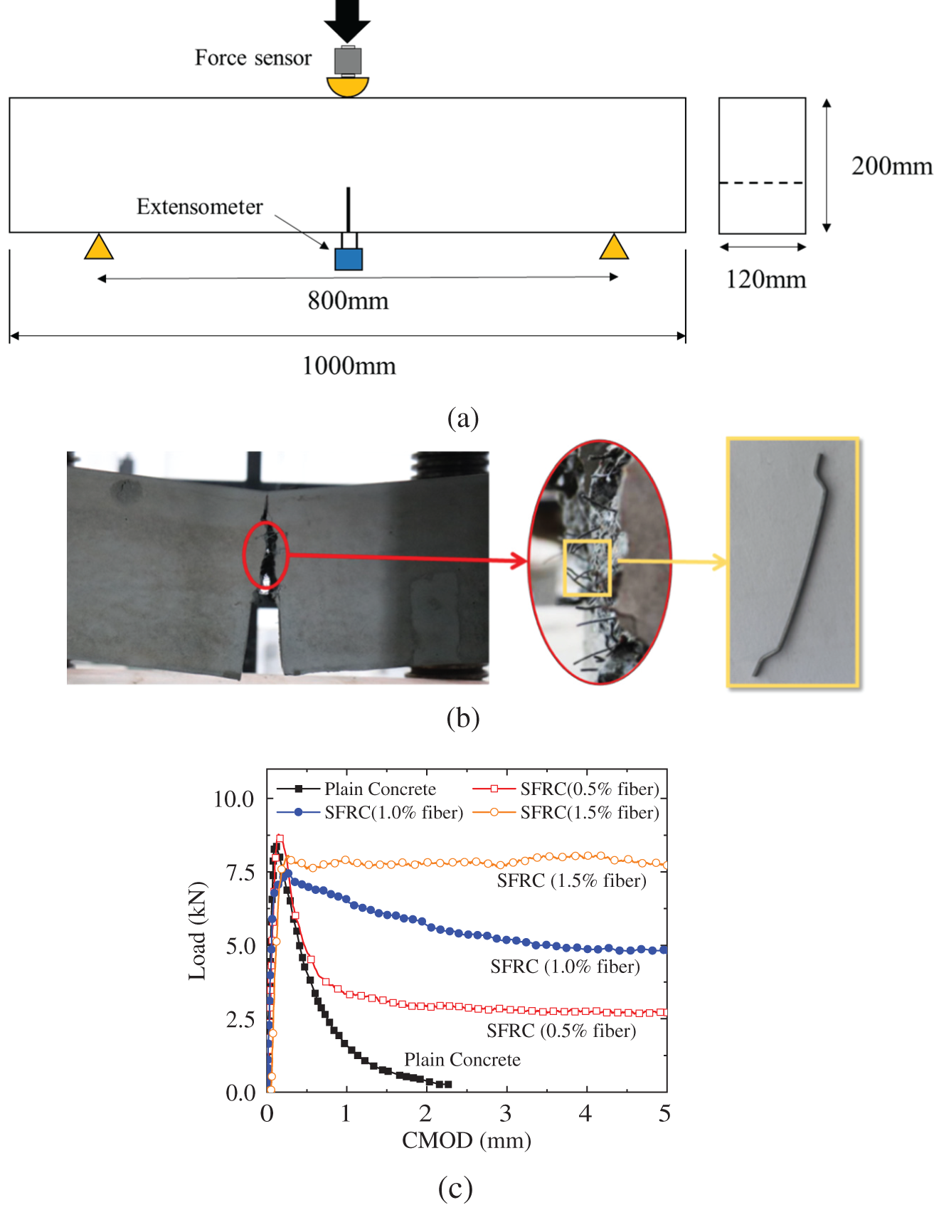
Figure 11: Experiments of the SFRC TPB beams: (a) loading scheme and geometry of the SFRC beam; (b) typical fracture behavior of the SFRC beam; (c) load-CMOD curves of the SFRC with different fiber contents
In this study, the fiber content was assumed to be 1.5% (mass ratio) because this fiber content can significantly enhance the bearing capacity and ductility of the concrete. Based on previous experimental and theoretical studies [24], the material parameters for the bridging effect (Eq. (7)) caused by the hooked-end fibers are as follows:
Figure 12: Load–deflection curves of the tunnel segment with SFRC: (a) under the simply support condition; (b) under double-hinged support condition
3.2.2 Segment Strengthen by External Bonding FRP Sheet
In recent years, externally bonded fiber-reinforced polymer (FRP) materials have been widely adopted to strengthen and rehabilitate degraded cracked reinforced concrete (RC) structures. This technique is highly appealing for addressing various structural issues, owing to its adaptability, ease of installation, and suitability for different structural elements.
According to previous studies [4,6,7], CFRP has excellent mechanical properties, including high tensile strength, low weight, and corrosion resistance, making it an ideal choice for enhancing the performance and durability of existing structures. Thus, in this study, a CFRP plate (as shown in Fig. 13) was selected as the reinforcement for the tunnel segment.
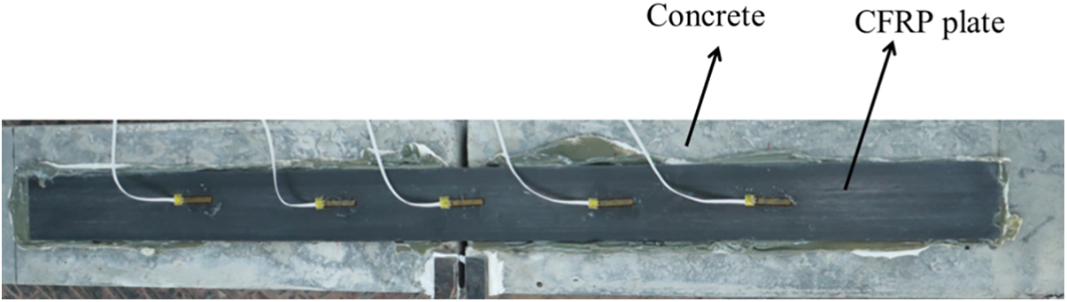
Figure 13: Typical example: CFRP externally bonded strengthening for concrete structures
According to previous research [9], the geometry information of the CFRP is the thickness
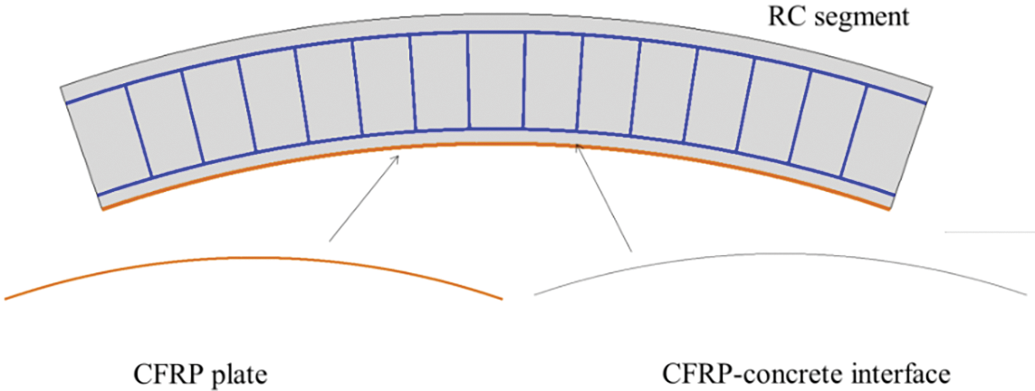
Figure 14: FE model of the segment strengthened by CFRP plate
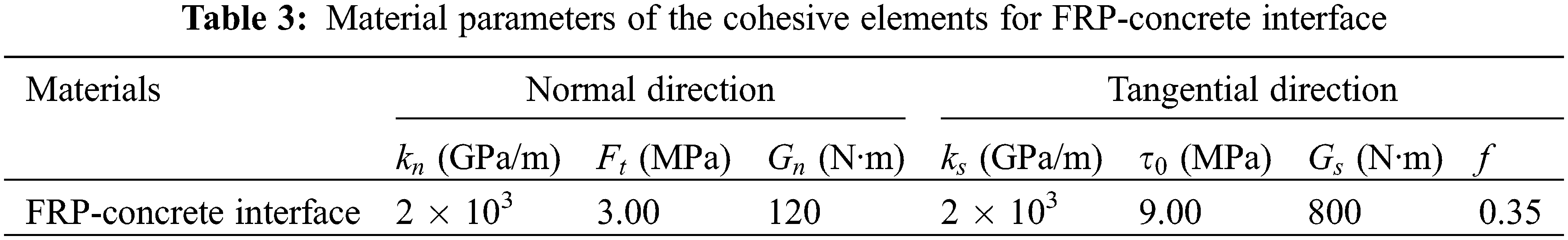
According to previous studies [7,9], the material properties provided by the factory, and the repeat trials, the material parameters for the FRP-concrete interface are listed in Table 3. The elastic modulus of the CFRP plate was approximately 160 GPa, and the plate was assumed to be undamaged because of its high strength.
The enhanced effect of the CFRP plate on the tunnel segment in the simulation is shown in Fig. 15. Under the simple support condition, the bearing capacity of the strengthened segment was approximately 1200 kN, as shown in Fig. 15a, which is approximately 1.3 times higher than that obtained from the segment with conventional concrete. In addition, as shown in Fig. 15c, the fracture pattern of the FRP-concrete interface primarily exhibited normal separation rather than tangential slip, indicating that the tensile strengthening effect of the CFRP plate was not fully utilized. Under the double-hinged support condition, the CFRP plate did not enhance the bearing capacity or durability, as shown in Fig. 15b. This is because the CFRP plates can only enhance the tensile strength of the RC structure and have a minimal impact on its shear strength (as shown in Fig. 15d, the segment exhibits shear failure). The tensile strengthening effect of the CFRP plate can also be seen in Fig. 15e. Once the crack propagated from the bottom of the tunnel segment, the bottom CFRP plate provided a high tensile stress, thereby limiting the expansion of the crack.
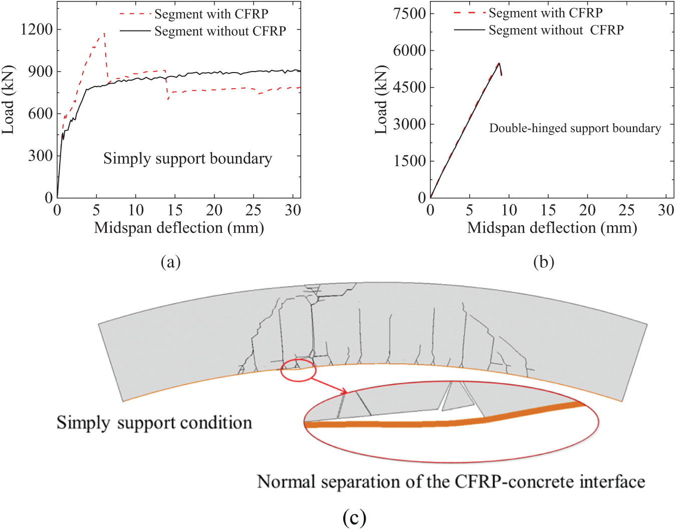
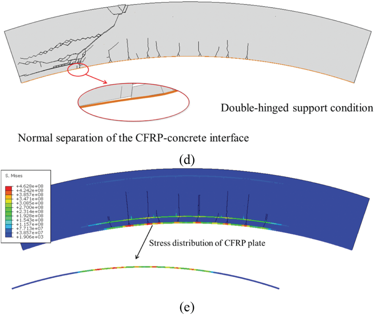
Figure 15: Simulation results of the CFRP strengthened tunnel segment: (a) load-deflection curves under simply support condition; (b) load-deflection curves under double-hinged support condition; (c) fracture pattern and stress under the support condition only; (d) fracture pattern under the double-hinged support condition; and (e) typical stress distribution of the CFRP plate when it works
In this study, a Finite Element (FE) model was formulated to analyze the tunnel segment throughout the entire fracture process based on previous studies. A cohesive zone model was implemented using the established FE model. The potential fracture surfaces of the concrete/SFRC, rebar-concrete interface, and FRP-concrete interfaces were characterized by cohesive elements. The corresponding constitutive model for the cohesive elements was incorporated into the FE model through a secondary development. A set of tunnel segment tests were conducted to validate the constructed model. The simulation results demonstrated that the proposed model can approximate the mechanical behavior and fracture pattern of a tunnel segment under varying boundary conditions. Finally, based on the Fuzhou Metro Shield Tunnel Construction Project, a series of numerical tests were conducted to evaluate the enhancement effects of two innovative reinforcement schemes (substituting concrete with SFRC and externally bonding a CFRP plate) on the behavior of the tunnel segments. The conclusions are summarized as follows:
1. By substituting concrete with SFRC, the strengthened tunnel segment exhibited improved bearing capacity. Under simple support and double-hinged support conditions, the maximum load of the SFRC segment was approximately 1.2 times and 1.1 times greater, respectively, compared to the load obtained from the concrete segment. Additionally, SFRC can enhance the durability of tunnel segments under double-hinged support conditions.
2. By externally bonding the CFRP plate, the bearing capacity of the segment was augmented by 1.3 times under simple support conditions. However, the CFRP plate did not have an enhancing effect under double-hinged support conditions. This was attributed to the failure of the FRP-concrete interface owing to normal separation, which resulted in the tensile strengthening effect of the CFRP plate not being fully leveraged.
Acknowledgement: None.
Funding Statement: This study was funded by the Scientific research startup Foundation of Fujian University of Technology (GY-Z21067 and GY-Z21026).
Author Contributions: The authors confirm contribution to the paper as follows: study conception and design: Gang Niu and Zhaoyang Jin; data collection: Zhaoyang Jin; analysis and interpretation of results: Wei Zhang and Yiqun Huang; draft manuscript preparation: Gang Niu, Wei Zhang and Yiqun Huang. All authors reviewed the results and approved the final version of the manuscript.
Availability of Data and Materials: The data that support the findings of this study are available from the corresponding author upon reasonable request.
Conflicts of Interest: The authors declare that they have no conflicts of interest to report regarding the present study.
References
1. Dai, J., Ueda, T., Sato, Y. (2005). Development of the nonlinear bond stress-slip model of fiber reinforced plastics sheet-concrete interfaces with a simple method. Journal of Composites for Construction, 9, 52–62. [Google Scholar]
2. Lu, X. Z., Teng, J. G., Ye, L. P., Jiang, J. J. (2005). Bond-slip models for FRP sheets/plates bonded to concrete. Engineering Structures, 27, 920–937. [Google Scholar]
3. Pellegrino, C., Tinazzi, D., Modena, C. (2008). Experimental study on bond behavior between concrete and FRP reinforcement. Journal of Composites for Construction, 12, 180–189. [Google Scholar]
4. Fawzia, S., Zhao, X., Al-Mahaidi, R. (2010). Bond-slip models for double strap joints strengthened by CFRP. Composite Structures, 92, 2137–2145. [Google Scholar]
5. Ko, H., Matthys, S., Palmieri, A., Sato, Y. (2014). Development of a simplified bond stress-slip model for bonded FRP-concrete interfaces. Construction and Building Materials, 68, 142–157. [Google Scholar]
6. Li, W., Huang, P., Chen, Z., Zheng, X., Yang, Y. et al. (2021). Bond behavior of fully bonded CFRP-concrete interface with improved double shear tests. Journal of Building Engineering, 43, 102866. [Google Scholar]
7. Zhang, W., Tang, Z., Yang, Y., Wei, J. (2021). Assessment of FRP-concrete interfacial debonding with coupled mixed-mode cohesive zone model. Journal of Composites for Construction, 25, 04021002. [Google Scholar]
8. Zhang, W., Huang, Y. (2022). Three-dimensional numerical investigation of mixed-mode debonding of FRP-concrete interface using a cohesive zone model. Construction and Building Materials, 350, 128818. [Google Scholar]
9. Huang, Y., Zhang, W., Liu, X. (2022). Assessment of diagonal macrocrack-induced debonding mechanisms in FRP-strengthened RC beams. Journal of Composites for Construction, 26, 04022056. [Google Scholar]
10. Wei, M., Xie, J., Zhang, H., Li, J. (2019). Bond-slip behaviors of BFRP-to-concrete interfaces exposed to wet/dry cycles in chloride environment. Composite Structures, 219, 185–193. [Google Scholar]
11. Dai, J., Gao, W. Y., Teng, J. G. (2013). Bond-slip model for FRP laminates externally bonded to concrete at elevated temperature. Journal of Composites for Construction, 17, 217–228. [Google Scholar]
12. di Ludovico, M., Prota, A., Manfredi, G., Cosenza, E. (2008). Seismic strengthening of an under-designed RC structure with FRP. Earthquake Engineering & Structural Dynamics, 37, 141–162. [Google Scholar]
13. Bousselham, A. (2010). State of research on seismic retrofit of RC beam-column joints with externally bonded FRP. Journal of Composites for Construction, 14, 49–61. [Google Scholar]
14. Chen, Z., Dong, S., Du, Y. (2021). Experimental study and numerical analysis on seismic performance of FRP confined high-strength rectangular concrete-filled steel tube columns. Thin-Walled Structures, 162, 107560. [Google Scholar]
15. Bedirhanoglu, I., Ilki, A., Triantafillou, T. C. (2022). Seismic behavior of repaired and externally FRP-jacketed short columns built with extremely low-strength concrete. Journal of Composites for Construction, 26, 04021068. [Google Scholar]
16. Karayannis, C. G. (2000). Analysis and experimental study for steel fibre pullout from cementitious matrices. Advanced Composites Letters, 9, 4. [Google Scholar]
17. Karayannis, C. G. (2000). Nonlinear analysis and tests of steel-fiber concrete beams in torsion. Structural Engineering and Mechanics, 9(4), 323–338. [Google Scholar]
18. Chalioris, C. E., Kosmidou, P. K., Karayannis, C. G. (2019). Cyclic response of steel fiber reinforced concrete slender beams: An experimental study. Materials, 12(9), 1398. [Google Scholar] [PubMed]
19. Marcos-Meson, V., Fischer, G., Edvardsen, C., Skovhus, T. L., Michel, A. (2019). Durability of steel fibre reinforced concrete (SFRC) exposed to acid attack-A literature review. Construction and Building Materials, 200, 490–501. [Google Scholar]
20. Kytinou, V. K., Chalioris, C. E., Karayannis, G. C. (2020). Analysis of residual flexural stiffness of steel fiber-reinforced concrete beams with steel reinforcement. Materials, 13, 2698. [Google Scholar] [PubMed]
21. Liao, L., Zhao, J., Zhang, F., Li, S., Wang, Z. (2020). Experimental study on compressive properties of SFRC under high strain rate with different fiber content and aspect ratio. Construction and Building Materials, 261, 119906. [Google Scholar]
22. Gao, D., Gu, Z., Wu, C. (2020). Bending behavior and deflection prediction of high-strength SFRC beams under fatigue loading. Journal of Materials Research and Technology, 9, 6143–6159. [Google Scholar]
23. Mari Bernat, A., Spinella, N., Recupero, A., Cladera, A. (2020). Mechanical model for the shear strength of steel fiber reinforced concrete (SFRC) beams without stirrups. Materials and Structures, 53, 1–20. [Google Scholar]
24. Huang, Y., Huang, J., Zhang, W., Liu, X. (2023). Experimental and numerical study of hooked-end steel fiber-reinforced concrete based on the meso-and macro-models. Composite Structures, 309, 116750. [Google Scholar]
25. Zhou, H., Chen, T., Li, L. (2012). Test and numerical analysis on performance of reinforced concrete segment in subway tunnel. Transactions of Tianjin University, 18(1), 57–61. [Google Scholar]
26. Li, X., Yan, Z., Wang, Z., Zhu, H. (2015). A progressive model to simulate the full mechanical behavior of concrete segmental lining longitudinal joints. Engineering Structures, 93(6), 97–113. [Google Scholar]
27. Zhao, H., Liu, X., Bao, Y., Yuan, Y., Bai, Y. et al. (2016). Simplified nonlinear simulation of shield tunnel lining reinforced by epoxy bonded steel plates. Tunnelling and Underground Space Technology, 51, 362–371. [Google Scholar]
28. Spagnuolo, S., Meda, A., Rinaldi, Z., Nanni, A. (2017). Precast concrete tunnel segments with GFRP reinforcement. Journal of Composites for Construction, 21(5), 04017020. [Google Scholar]
29. Eng, T. Z., Wu, X., Gao, P., Zhou, L., Geng, F. et al. (2019). Secondary cracks and mechanical behavior prediction of concrete segments after FRP confinement. Iranian Journal of Science and Technology, Transactions of Civil Engineering, 43, 769–779. [Google Scholar]
30. Eng, T. Z., Gao, P., Zhu, Q., Zhu, A. (2019). Experimental and numerical modeling on fatigue damage in FRP and PM confinement tilt’s fulcrum RC segments under humid and constant amplitude loading. KSCE Journal of Civil Engineering, 23, 3409–3419. [Google Scholar]
31. Demir, M. (2019). A Method for the design of FRC tunnel linings reinforced with FRP bars (Master Thesis). The Graduate School of Natural and Applied Sciences, Middle East Technical University, Turkey. [Google Scholar]
32. Liu, X., Jiang, J., Wang, G., Wang, J., Xu, R. (2020). Debonding analysis of curved RC beams externally bonded with FRP plates using CZM. Engineering Structures, 205, 110103. [Google Scholar]
33. Hosseini, S. M., Mousa, S., Mohamed, H. M., Ferrier, E., Benmokrane, B. (2023). Experimental and analytical investigation of precast fiber-reinforced concrete (FRC) tunnel lining segments reinforced with glass-FRP bars. Tunnelling and Underground Space Technology, 139, 105230. [Google Scholar]
34. Abbas, S., Nehdi, M. L. (2018). Mechanical behavior of RC and SFRC precast tunnel lining segments under chloride ions exposure. Journal of Materials in Civil Engineering, 30, 04018047. [Google Scholar]
35. Tang, K., Wilkinson, S. (2020). Corrosion resistance of electrified railway tunnels made of steel fibre reinforced concrete. Construction and Building Materials, 230, 117006. [Google Scholar]
36. Xu, H., Wang, Z., Shao, Z., Jin, H., Li, Z. et al. (2020). Experimental study on crack features of steel fiber reinforced concrete tunnel segments subjected to eccentric compression. Materials Today Communications, 25(7), 101349. [Google Scholar]
37. Yang, K., Yan, Q., Zhang, C. (2021). Three-dimensional mesoscale numerical study on the mechanical behaviors of SFRC tunnel lining segments. Tunnelling and Underground Space Technology, 113, 103982. [Google Scholar]
38. López, C. M., Carol, I., Aguado, A. (2008). Meso-structural study of concrete fracture using interface elements. I: Numerical model and tensile behavior. Materials and Structures, 41, 583–599. [Google Scholar]
39. López, C. M., Carol, I., Aguado, A. (2008). Meso-structural study of concrete fracture using interface elements. II: Compression, biaxial and Brazilian test. Materials and Structures, 41, 601–620. [Google Scholar]
40. Wang, X. F., Yang, Z. J., Yates, J. R., Jivkov, A. P., Zhang, C. (2015). Monte Carlo simulations of mesoscale fracture modelling of concrete with random aggregates and pores. Construction and Building Materials, 75, 35–45. [Google Scholar]
41. Huang, Y., Hu, S. (2019). A cohesive model for concrete mesostructure considering friction effect between cracks. Computers and Concrete, An International Journal, 24, 51–61. [Google Scholar]
42. Razaqpur, A. G., Lamberti, M., Ascione, F. (2020). A nonlinear semi-analytical model for predicting debonding of FRP laminates from RC beams subjected to uniform or concentrated load. Construction and Building Materials, 233(11), 117838. https://doi.org/10.1016/j.conbuildmat.2019.117838 [Google Scholar] [CrossRef]
43. Razaqpur, A. G., Lamberti, M., Ascione, F. (2020). Debonding evolution in nonlinear FRP-retrofitted RC beams with cohesive interface. Composite Structures, 236(2), 111858. https://doi.org/10.1016/j.compstruct.2020.111858 [Google Scholar] [CrossRef]
44. Li, B., Zhang, Z., Wang, X., Liu, X. (2019). Investigation on cohesive zone model of bolted joint for water conveyance tunnel lining. Engineering Computations, 36(5), 1449–1468. https://doi.org/10.1108/EC-07-2018-0310 [Google Scholar] [CrossRef]
45. Xie, J., Huang, X., Zhang, Z., Jin, G. (2023). Cohesive zone model-based analyses of localized leakage of segmentally lined tunnels. Frontiers of Structural and Civil Engineering, 17, 503–521. [Google Scholar]
46. Liu, J., Zhang, X., Lv, G., Wang, K., Han, B. et al. (2021). Study on crack development of concrete lining with insufficient lining thickness based on czm method. Materials, 14, 7862. [Google Scholar] [PubMed]
47. Comité, E. D. B. (1993). CEB-FIP model code 1990: Design code. Thomas Telford Publishing. [Google Scholar]
48. Simulia, D. S. (2016). ABAQUS analysis user’s manual (version 6.14). Providence, RI, USA: Dassault Systèmes Simulia. [Google Scholar]
Cite This Article
 Copyright © 2024 The Author(s). Published by Tech Science Press.
This work is licensed under a Creative Commons Attribution 4.0 International License , which permits unrestricted use, distribution, and reproduction in any medium, provided the original work is properly cited.
 Downloads
 Citation Tools