
 Submit a Paper
 Propose a Special lssue
 Open Access
ARTICLE

Safety Analysis of Precast Pier Box for a Sea-Crossing Bridge During Hoisting
1 CCCC Fourth Harbor Engineering Institute Co., Ltd., Guangzhou, 510230, China
2 Key Laboratory of Environment and Safety Technology of Transportation Infrastructure Engineering, CCCC, Guangzhou, 510230, China
3 School of Civil Engineering and Transportation, South China University of Technology, Guangzhou, 510640, China
4 College of Architecture and Electrical Engineering, Hezhou University, Hezhou, 542899, China
* Corresponding Authors: Shoulong Zhang. Email: ; Jintuan Zhang. Email:
# These authors contributed equally to this work
(This article belongs to the Special Issue: Durability Assessment of Engineering Structures and Advanced Construction Technologies)
Structural Durability & Health Monitoring 2026, 20(2), 7 https://doi.org/10.32604/sdhm.2025.072958
Received 08 September 2025; Accepted 11 November 2025; Issue published 31 March 2026
 View Full Text
 Download PDF
Abstract
To ensure the safety of the integral hoisting of precast pier boxes for sea-crossing bridges, this study focused on the sidewall height of the pier box and the width of the hoisting sling as core variables, established a finite element model using ABAQUS, and conducted a safety analysis of the hoisting process. The results showed that optimal structural safety and cost-effectiveness were achieved by first casting the concrete base plate of the pier box, then constructing the sidewalls to a height of 500 mm, and subsequently using REE-100T eye & eye round slings for hoisting. Additionally, the implementation of local reinforcement measures (symmetrical stiffeners and steel sleeves) at the circular holes in the bottom plate of the pier box significantly alleviated stress concentration at these holes, effectively avoiding the risk of cracking caused by excessive local stress during the hoisting process. On-site hoisting practices verified the effectiveness of this optimized scheme, and the relevant research findings can provide a reference for the safety control of hoisting operations for similar large-scale precast components.Keywords
With the increasing demand for infrastructure construction, mass concrete has been widely used in projects such as bridges, tunnels, and docks. During the construction of large-scale concrete structures, the integral hoisting of the precast components is a critical process that improves construction efficiency and reduces environmental impacts, making the safety analysis of hoisting operations crucial.
In engineering practice, the assessment of structural performance and safety during the integral hoisting of large precast components primarily relies on two technical approaches: numerical simulation and field monitoring. While field monitoring provides direct validation of actual stress states [1,2], the finite element method has become the preferred tool for preliminary safety assessment and scheme optimization due to its superior capability in modeling complex geometries, material properties, boundary conditions, and conducting parametric analysis and risk prediction in a controlled virtual environment [3–5]. Zhang and Zhou (2012) [6] employed floating cranes to hoist large segments of steel box girders during the construction of the Chongqi Bridge, and through Finite Element (FE) simulation, identified that the maximum stress in the box girder during hoisting occurred at the connection between the lifting lugs and the top plate. Sheng et al. (2016) and Liu et al. (2017) [7,8] employed finite element verification to assess the strength and stability of the torch during the integral hoisting process, proposing reinforcement measures for structurally weak areas based on critical points. Duan et al. (2022) [9] utilized ABAQUS finite element analysis to investigate the stress conditions of the bottom and top plates at the mid-span section of the large-span steel box girders in a continuous rigid frame bridge under various hoisting conditions.
In the field of precast concrete component hoisting, the application of finite element analysis is also deepening. Early research primarily focused on documenting construction methods for specific components like “Y” columns or arch ribs [10,11]. Recently, scholars have begun using numerical simulation to reveal the underlying mechanical mechanisms during hoisting. Li et al. (2014) [12] conducted a FE simulation of the large-segment hoisting construction process for the Hong Kong-Zhuhai-Macao Bridge, exploring the complex stress conditions at the hoisting points. Cheng et al. (2022, 2024) [13,14] studied the stress responses of a cable-stayed bridge’s cable tower [13] and concrete segmental box girders [14] under different hoisting schemes, respectively. Xie et al. (2023) [15] revealed that even slight lifting imbalance can drastically increase tensile stress and cracking risk in prefabricated plates, highlighting the critical importance of load distribution. Wang et al. (2020) [16] proposed a geometric state transfer method for the hoisting installation of large-segment steel box girders, enabling precise control of manufacturing parameters, annular joint width, and support positioning through geometric state equations and transfer matrices. Wang et al. (2025) [17] systematically analyzed the mechanical behavior of symmetric prefabricated concrete bodies and metal connecting components during hoisting and overturning, providing guidance for the selection of steel tie rods in assembly structures.
Currently, most construction schemes typically employ hoisting lugs or holes drilled in the concrete structure for hoisting, making “hoisting point optimization” a core research topic for hoisting safety. Li and Li (2011) [18] proposed a hoisting point optimization criterion aiming to minimize structural strain energy. Tian et al. (2016) [19] developed an “asynchronous analysis method” to address the most unfavorable conditions caused by non-synchronous lifting in long-span spatial steel structures. Tong et al. (2023) [20] employed hierarchical Particle Swarm Optimization (PSO) algorithms to optimize the position and number of lifting points. Ding et al. (2024) [21] established that using upper radial cables as traction points and controlling their force evolution are crucial for structural stability and achieving the design configuration during oblique traction-hoisting of cable-truss structures. Further extending to concrete applications, Cao and Chen (2024) [22] used FE simulation to study the influence of lifting lug position on the mechanical performance of a nuclear power plant’s steel liner during hoisting, emphasizing the critical role of lug arrangement. Song et al. (2023) [23] confirmed through a detailed FE study that adopting a four-hoisting-point scheme, with points located near the webs, is essential for precast segmental composite box girders with corrugated steel webs, while Yu (2023) [24] addressed the challenges of precise positioning and temporary fixation for steel-concrete composite segments in a long-span hybrid girder bridge. However, the critical interaction between hoisting slings and large-scale precast concrete components remains underexplored, posing a potential risk of component cracking due to excessive local stresses during hoisting operations.
Focusing on the issue, this paper investigated the safety control during the hoisting of a precast concrete pier box for a sea-crossing bridge engineering project in the United Arab Emirates. The study established a finite element model and pioneered the use of “sidewall height” and “hoisting sling width” as dual control variables to quantitatively analyze their synergistic impact. The ABAQUS-based analysis deciphered the interplay between sidewall constraint and sling contact area, yielding optimized casting heights and sling specifications. Furthermore, the incorporation of symmetrical stiffeners and steel sleeves around circular holes proved effective in mitigating stress concentration. This work fills a critical gap in the systematic safety analysis of such structures and offers valuable methodologies for similar hoisting projects.
2 Engineering Project Introduction
The 7th and 8th Sea-Crossing Bridge projects on Reem Island, located adjacent to the capital of the United Arab Emirates, Abu Dhabi, feature a bored pile foundation for the entire bridge, with the marine section mainly utilizing ‘V’ shaped piers. Prior to the construction of the V-shaped pier caps, it is imperative to install precast concrete pier boxes, within which the cap construction is executed. As illustrated in Fig. 1, the project adopted an overall hoisting scheme wherein two hoisting slings pass under the bottom of the precast pier box, converging the hoisting points to the hooks of a square lifting frame, which ensures balanced hoisting through the uniform elevation of the square steel frame. The external dimensions of the pier box are 14.9 m × 7.4 m × 2.4 m, with both the bottom slab and sidewalls measuring 0.25 m in thickness. The concrete is specified to be of grade C45, and the total weight of the pier box is approximately 120 t. The formwork for the pier box utilizes a set of standardized wooden forms available locally, with the bottom slab and sidewalls being poured in two separate stages before and after the pier box is hoisted.
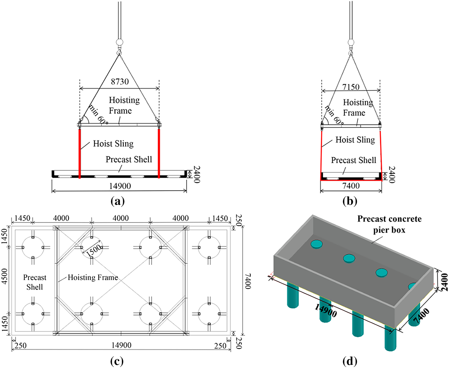
Figure 1: Schematic diagram of precast concrete pier box during hoisting (mm). (a) Front view; (b) Left view; (c) Vertical view; (d) Three-dimensional diagram
To reduce the risks associated with the hoisting process, the operation was carried out under the conditions of low wind speed and favorable weather. This decision was justified by the local climatic conditions and strict construction controls. The project site on Reem Island, Abu Dhabi, experienced a tropical desert climate with consistently low wind speeds. According to data from the local meteorological authority, the average daily wind speed from November to March ranges only from 3.3 to 4.5 m/s, which was significantly below the maximum allowable wind speed of 10.8 m/s (equivalent to Force 6 on the Beaufort scale) for lifting operations as specified [25]. Furthermore, the construction protocol explicitly restricted hoisting activities to conditions with wind speeds ≤5 m/s, no precipitation, and no fog, with real-time wind monitoring equipment deployed on site to ensure strict adherence. Given these mitigating factors, the impact of wind load was considered negligible for this specific analysis and was not separately simulated. The simulation incorporated the dynamic effects induced by the acceleration at the instant of hoisting were addressed by applying a dynamic coefficient of 1.2 [26].
3 Finite Element Modeling of Hoisting Slings and the Pier Box
The hoisting process of the precast pier box was simulated using ABAQUS/CAE, with specific details provided in Fig. 2. The pier box, composed of concrete and the reinforcement cage, was modeled using three-dimensional, 8-node linear brick, reduced-integration solid elements (C3D8R) for both the concrete structure and the hoisting slings. This element type is particularly suitable for simulating concrete behavior as it effectively captures large deformations and complex contact interactions while maintaining robustness against mesh distortion. The reinforcing bars were modeled using 2-node linear 3D truss elements (T3D2), which are specifically designed for members that primarily carry axial forces.
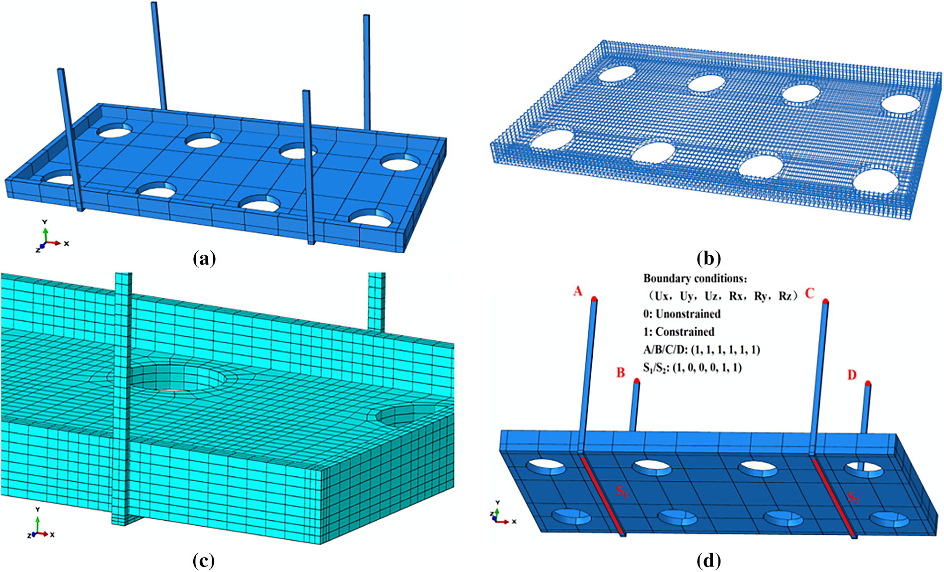
Figure 2: Three dimensional model of pier box hoisting. (a) The overall hoisting model; (b) Reinforcement cage; (c) Mesh of the model; (d) Boundary condition
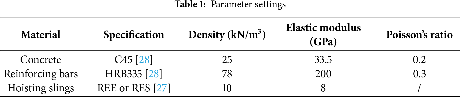
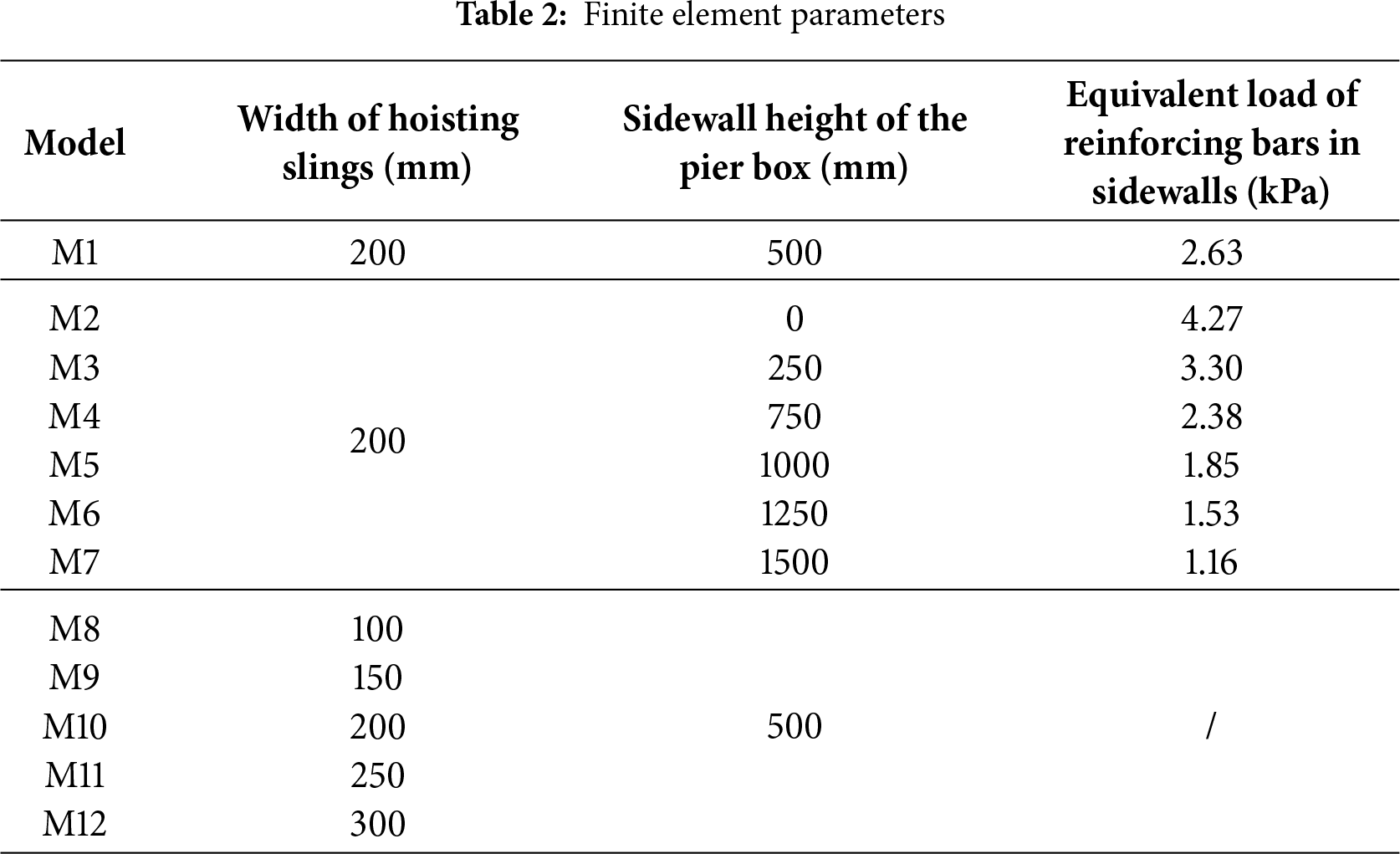
In accordance with the construction requirements, hoisting slings with a minimum working load capacity of 50 t were selected, specifically endless round slings (RES) or eye & eye round slings (REE) [27], which were made of 100% high-strength polyester industrial filaments and had a diameter of at least 119 mm. During the actual hoisting process, the round slings exhibit a tendency to tighten and contract, necessitating their simplification to strip-like configurations in the finite element simulation. The material parameters of concrete, reinforcing bars and hoisting slings are detailed in Table 1.
As depicted in Fig. 2c, the entire concrete pier box was meshed with a grid size of 300 mm, with refinements applied to achieve a 150 mm grid size at the contact points with the hoisting slings to capture the higher stress gradients anticipated in these areas accurately. The bottom plate of the pier box was divided into 3 layers along its thickness direction. The hoisting slings were discretized with a mesh size of 120 mm, comprising three layers along the thickness direction and two layers along the width direction.
3.3 Constraints and Load Settings
A ‘face-to-face’ contact relationship was established between the internal surface of the hoisting slings and the external surface of the pier box, with the normal contact set to ‘hard’ and the tangential contact defined by a penalty function with a friction coefficient of 0.3. The reinforcing cage was entirely “embedded” within the pier box, which perfectly bonded the rebar nodes to the concrete solid elements, simulating their composite action. As shown in Fig. 2d, to simulate a four-point hoisting scenario, all degrees of freedom at points A, B, C, and D on the top of the hoisting slings were constrained. To replicate the tension state of the hoisting slings, the rotational degrees of freedom along the x-axis, as well as the rotational degrees of freedom along the y-axis and z-axis of the bottom of the slings (designated as S1 and S2), were also constrained. Since the reinforcing bars in the sidewalls of the pier box were modeled as truss elements (T3D2), which cannot interact with the solid elements of the pier box, the reinforcing bars in the unfiltered sidewalls were converted into equivalent loads and applied to the sidewalls. A gravity load, representing the self-weight of the entire system, was applied using the “Gravity” load module in ABAQUS, which applied a uniform acceleration field to the entire model. The standard gravitational acceleration of −9.81 m/s2 was specified in the global Y-direction, consequently generating the corresponding body force throughout the structure based on the defined material densities.
4 Safety Analysis of Pier Box During Hoisting
This article primarily investigated the impact of the sidewall height of the pier box and the width of the hoisting slings on the safety of the pier box during hoisting.
As delineated in Table 2, a reference model (Model M1), characterized by a sidewall height of 500 mm and a hoisting sling width of 200 mm, served as a baseline to assess the influence of varying casting heights of the sidewalls on the restraint effect of the concrete bottom plate, as well as the impact of different hoisting sling widths on the load-bearing performance of the pier box. It was observed that an increase in the sidewall height corresponded to a decrease in the equivalent load of the reinforcing bars. This study conducted a parametric finite element analysis and selected the most reasonable set of parameters, which were compared with the code values after applying a dynamic factor of 1.2.
4.1 The Influence of Sidewall Height on the Structural Performance of the Pier Box
A hoisting sling width of 200 mm was selected to investigate the impact of various sidewall pouring heights of the pier box (0, 250, 500, 750, 1000, 1250, 1500 mm) on the maximum displacement uw,max, maximum tensile stress σwt,max, maximum compressive stress σwc,max, and the maximum stress σws,max in the reinforcement cage during the hoisting process.
4.1.1 The Influence of Sidewall Height on the Maximum Displacement uw,max of the Pier Box
The sidewall height significantly influences the structural response, with the maximum displacement uw,max exhibiting a clear three-stage evolution as the height increases:
(1) With the sidewall height of the pier box being 0, the absence of restraining effect from the sidewalls on the bottom slab resulted in the maximum displacement uw,max being the largest during the hoisting process, which was 19.14 mm and located at the center of the bottom plate, as shown in Fig. 3a. This behavior is consistent with the classical bending theory of a plate simply supported at the hoisting points [29].
(2) At low sidewall heights (250 and 500 mm), the shift of the maximum displacement to the short-side sidewalls was attributed to their pronounced size effect under combined bending and shear [30,31]. In this configuration, with the hoisting points acting as supports, the short-side sidewalls functioned as vertical cantilevers with a small shear-span ratio, rendering them susceptible to significant shear deformations alongside bending. Their concurrently reduced effective stiffness against out-of-plane moments was insufficient to resist deflections induced by the self-weight, sidewall mass, and equivalent reinforcement loads. As a result, the mid-span deflection of the short-side walls surpassed the bending-governed displacement at the bottom plate center, leading to the observed shift in the maximum displacement location.
(3) As the sidewall height increases to 750 mm and beyond, the shear-span ratio increased, shifting the structural behavior towards bending dominance. The deep-beam effect and out-of-plane stiffness of the sidewalls were significantly enhanced. This provided effective constraint to the bottom slab and suppresses out-of-plane deformation of the sidewalls themselves. Accordingly, the maximum displacement uw,max decreased to 11.98 at 750 mm height. However, with further height increase to 1500 mm, the additional self-weight became dominant, causing the displacement to rebound upward as shown in Fig. 4.
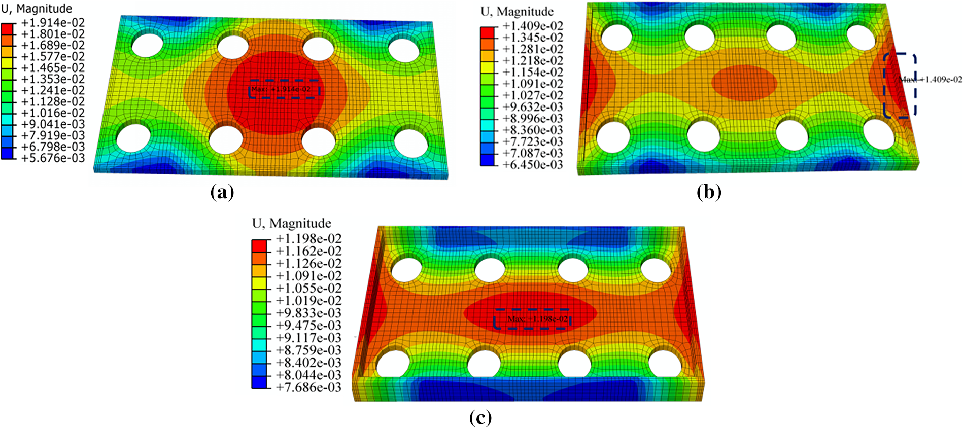
Figure 3: Displacements contour diagram of the pier boxes. (a) M2 (without sidewalls); (b) M3 (with a sidewall height of 250 mm); (c) M4 (with a sidewall height of 750 mm)

Figure 4: The maximum displacement of the pier box uw,max varied with sidewall heights
4.1.2 The Influence of Sidewall Height on the Maximum Tensile Stress σwt,max of the Pier Box
As depicted in Fig. 5a, the maximum tensile stress σwt,max in the pier box, located at the bottom of the center hole in the bottom plate, decreased from 2.66 to 2.11 MPa as the sidewall height increased from 0 to 500 mm. Fig. 5b,c reveals that with the sidewall height increasing to 750 and 1000 mm, the maximum tensile stress σwt,max rose to 2.51 MPa due to the significant squeezing effect of the hoisting slings on the sidewalls of pier box. The stress appeared on the upper regions of the contact area between the hoisting slings and the bottom plate of the pier box (near the corner between the sidewall and bottom plate) and on the inner side of the contact area between the hoisting slings and the top of the sidewalls, respectively. Upon elevating the sidewall height to 1500 mm, the maximum tensile stress σwt,max gradually decreased to 2.23 MPa. Fig. 5d indicates that the maximum tensile stress σwt,max was located near the contact area at the corner where the hoisting slings met the bottom plate, which was attributed to the relatively limited contact area between the hoisting slings and the pier box while coupled with the significant self-weight of the pier box, leading to higher shear stress at the chamfered corners. The overall variation of σwt,max with sidewall height is summarized in Fig. 6.
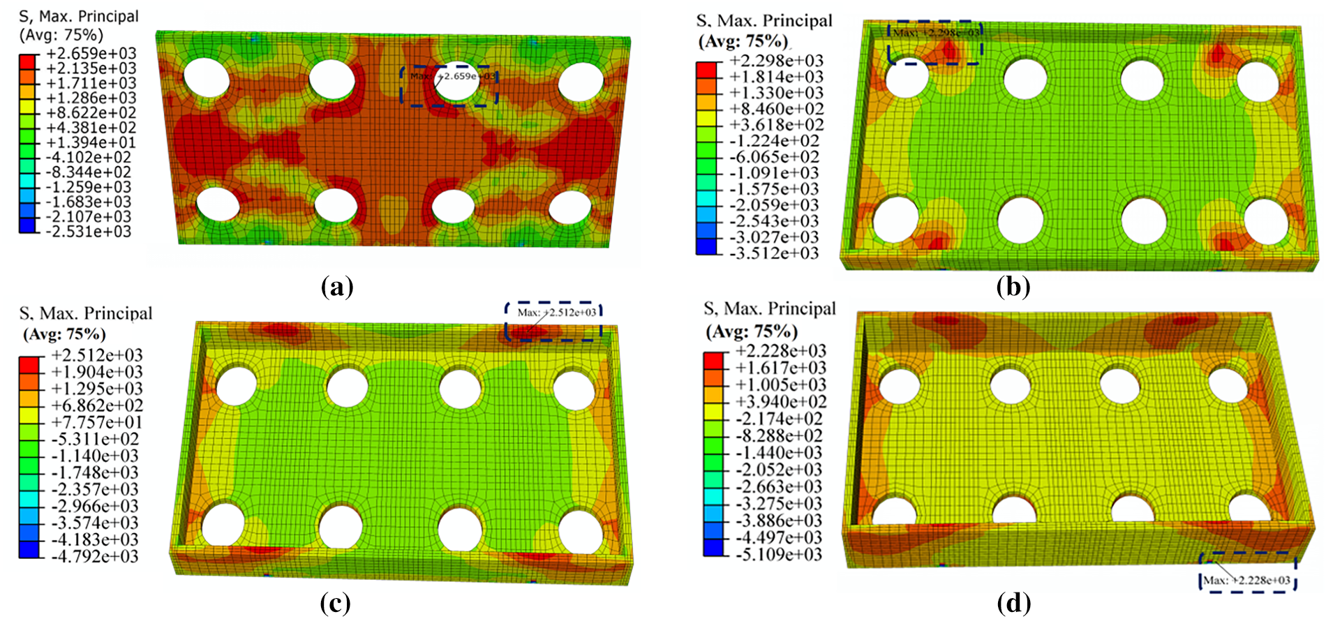
Figure 5: Tension stress contour diagram of the pier boxes. (a) M2 (without sidewalls); (b) M4 (with a sidewall height of 750 mm); (c) M5 (with a sidewall height of 1000 mm); (d) M7 (with a sidewall height of 1500 mm)
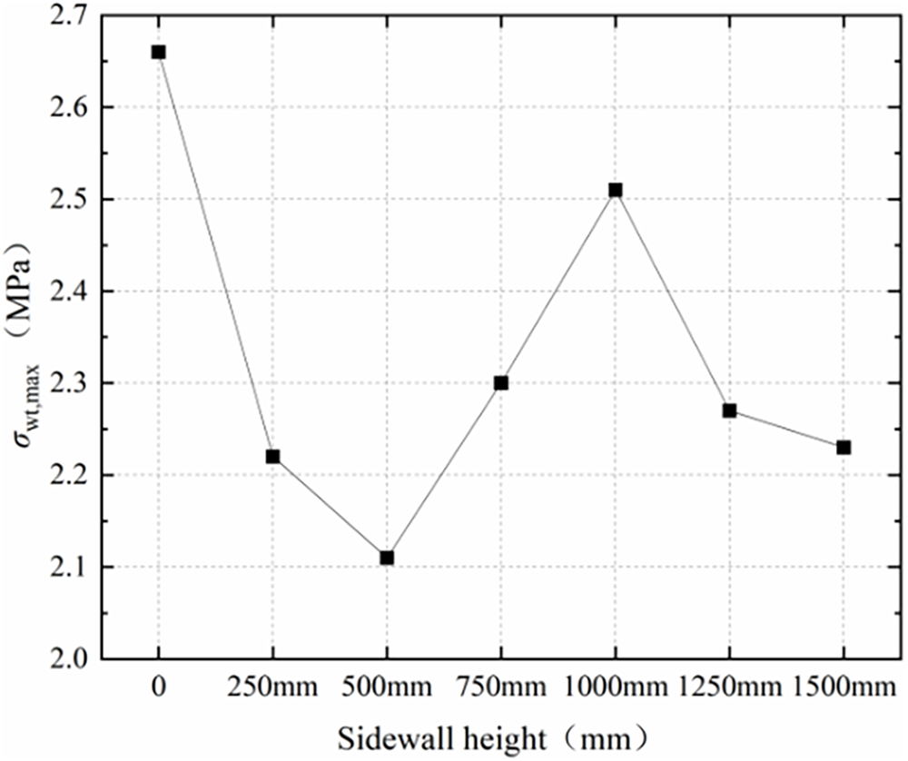
Figure 6: The maximum tension stress of the pier box σwt,max varied with sidewall heights
4.1.3 The Influence of Sidewall Height on the Maximum Compressive Stress σwt,max of the Pier Box
As illustrated in Fig. 7, the maximum compressive stress σwt,max of the pier box during hoisting was primarily localized near the contact area at the corner between the hoisting slings and the bottom plate, irrespective of the sidewall pouring height. As the sidewall height grew from 0 to 750 mm, the maximum compressive stress σwt,max decreased from 16.74 to 14.24 MPa, coinciding with a reduction in the maximum displacement uw,max of the pier box during hoisting. However, upon further increasing the sidewall height to 1500 mm, the maximum compressive stress σwt,max rebounded to 15.97 MPa, as shown in Fig. 8, which was attributed to the continuous increase in the maximum displacement uw,max.
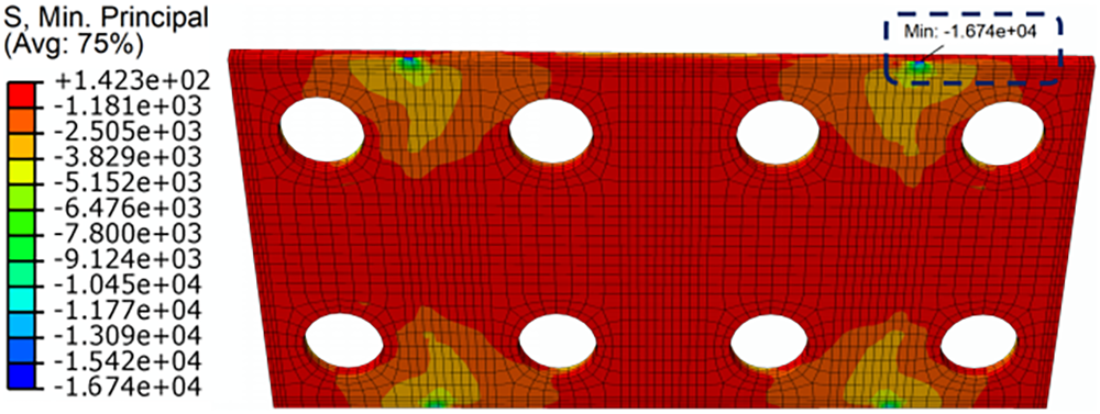
Figure 7: Compressive stress contour diagram of pier box (taking M2 without sidewalls as an example)
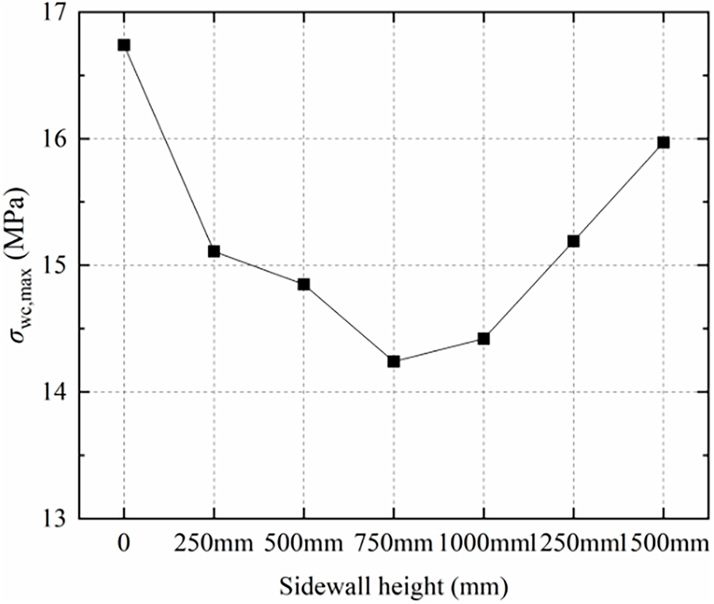
Figure 8: The maximum compressive stress of the pier box σwt,max varied with sidewall heights
4.1.4 The Influence of Sidewall Height on the Maximum Stress σws,max of the Reinforcement Cage
At a sidewall pouring height of 0, the maximum stress σws,max experienced by the reinforcement cage was 169.30 MPa, occurring at the concentrated stress area at the center hole of the bottom plate, as shown in Fig. 9a. As the sidewall height increased from 0 to 1000 mm, the maximum stress σws,max of the reinforcement cage gradually decreased to 23.88 MPa, shifting from the bottom plate to the top of the long-side sidewall and eventually locating near the contact area between the hoisting slings and the bottom plate. Further increasing the sidewall height to 1500 mm resulted in a gradual increase in the maximum stress σws,max, which rose to 24.91 MPa, as depicted in Fig. 10.
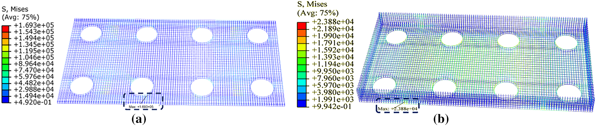
Figure 9: Stress contour diagram of the reinforcement cage. (a) M2 (without sidewalls); (b) M5 (with a sidewall height of 1000 mm)
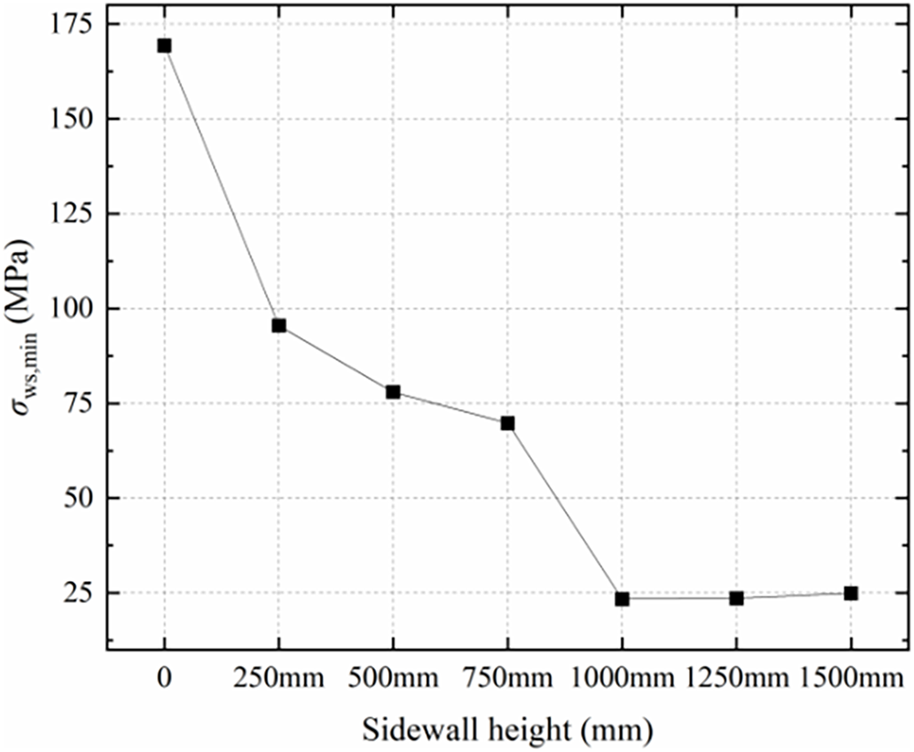
Figure 10: The maximum stress of the reinforcement cage σws,max varied with sidewall heights
4.2 The Influence of Hoisting Sling Width on the Structural Performance of the Pier Box
A casting height with 500 mm for the sidewall of the precast pier box was set to investigate the impact of various hoisting sling widths (100, 150, 200, 250, 300 mm) on the maximum displacement us,max, maximum tensile stress σst,max, maximum compressive stress σsc,max, and the maximum stress in the reinforcing cage σss,max during the hoisting process.
4.2.1 The Influence of Hoisting Sling Width on the Maximum Displacement us,max of the Pier Box
As illustrated in Fig. 11, the location of the maximum displacement consistently occurred at the midsection of the short-side sidewall across all sling widths analyzed at a sidewall height of 500 mm for the pier box, and the maximum displacement us,max during hoisting decreased from 20.78 to 10.05 mm as the sling width increased from 100 to 300 mm, which was quantified in Fig. 12.
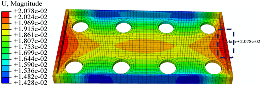
Figure 11: Displacements contour diagram of the pier box (taking M8 with a hoisting sling width of 100 mm as an example)
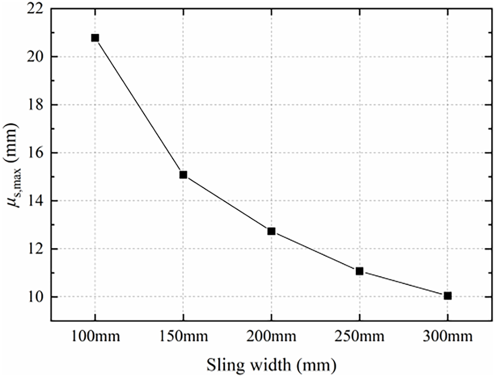
Figure 12: The maximum displacement of the pier box us,max varied with hoisting sling widths
4.2.2 The Influence of Hoisting Sling Width on the Maximum Tensile Stress σst,max of the Pier Box
For a hoisting sling width of 100 mm, the maximum tensile stress σst,max experienced by the pier box during hoisting was 2.44 MPa, as shown in Fig. 13a. As the hoisting sling width increased to 300 mm, the maximum tensile stress σst,max decreased to 2.07 MPa, exhibiting a consistent downward trend as summarized in Fig. 14. All maximum stress points located at the concentrated stress area at the center hole of the pier box’s bottom plate.
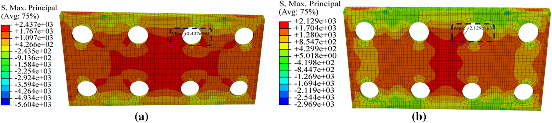
Figure 13: Tension stress contour diagram of pier boxes. (a) M8 (with a hoisting sling width of 100 mm); (b) M9 (with a hoisting sling width of 150 mm)
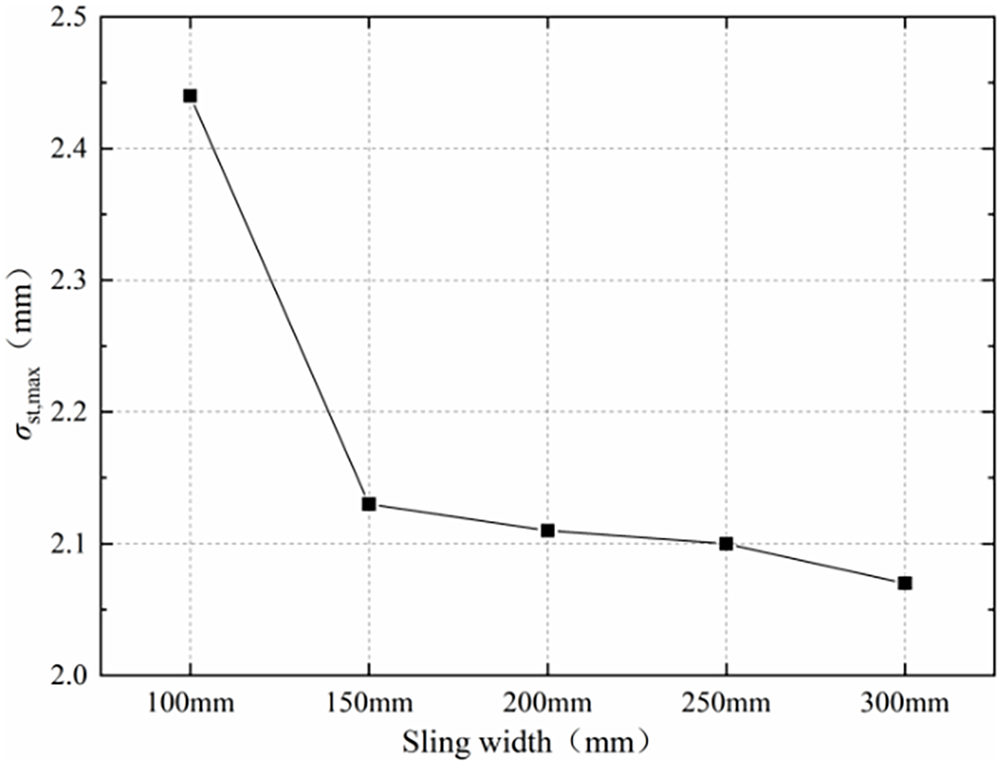
Figure 14: The maximum tension stress of the pier box σst,max varied with hoisting sling widths
4.2.3 The Influence of Hoisting Sling Width on the Maximum Compressive Stress σsc,max of the Pier Box
As shown in Fig. 15, the maximum compressive stress was consistently located at the contact position where the hoisting slings met the corner of the pier box’s bottom plate. With the increase in hoisting sling width from 100 to 300 mm, σsc,max gradually decreased from 16.51 to 10.96 MPa, a trend which was clearly quantified in Fig. 16.
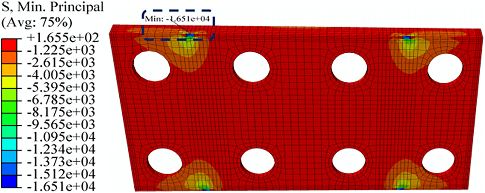
Figure 15: Compressive stress contour diagram of pier box (taking M8 with a hoisting sling width of 100 mm as an example)
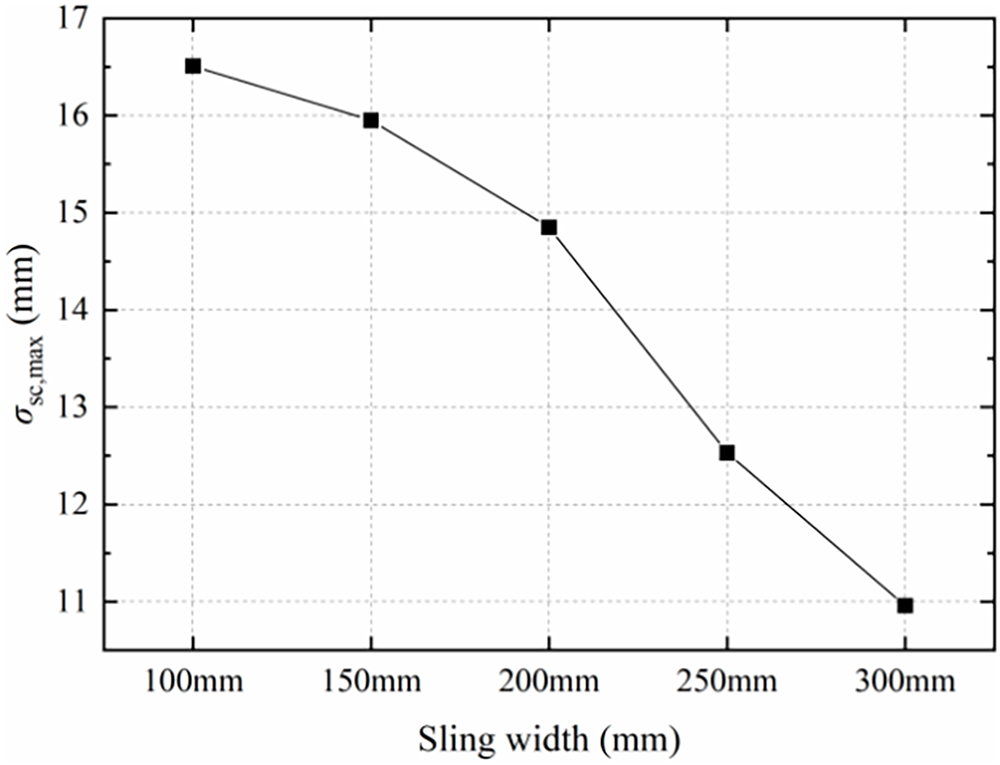
Figure 16: The maximum compressive strees of the pier box σsc,max varied with hoisting sling widths
4.2.4 The Influence of Hoisting Sling Width on the Maximum Stress σss,max of the Reinforcement Cage
The maximum stress in the reinforcement cage was consistently located near the inner side of the contact area between the hoisting slings and the top of the pier box’s sidewall, as depicted in Fig. 17. Expanding the width of the hoisting sling from 100 to 300 mm resulted in a gradual decrease in the maximum stress σss,max experienced by the reinforcement cage in the pier box from 87.02 to 74.14 MPa during hoisting, demonstrating a clear reduction trend as systematically presented in Fig. 18.
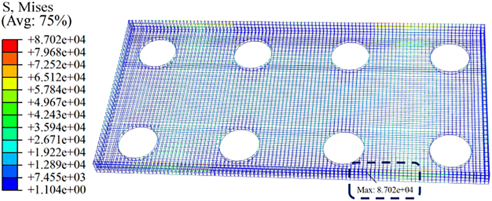
Figure 17: Stress contour diagram of the reinforcement cage (taking M8 with a hoisting sling width of 100 mm as an example)
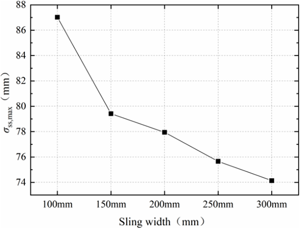
Figure 18: The maximum stress of the reinforcement cage σss,max varied with hoisting sling widths
4.3 Displacement and Stress Analysis of the Pier Box during Hoisting
As detailed in Sections 3.1 and 3.2, Figs. 19 and 20 demonstrate the influence of the sidewall heights and hoisting sling widths on the structural performance of the concrete pier box during hoisting. The parametric study on sidewall height revealed that a height of 500 mm minimized the maximum tensile stress in the pier box under the condition of a 200 mm sling width. This optimum arises from a balance between structural stiffness and self-weight: the sidewalls at this height provide sufficient restraint to the bottom slab without introducing excessive mass that would dominate the stress response. Consequently, in the actual hoisting construction, the pier box was initially cast with a 250 mm-thick bottom plate and a 500-mm-high sidewall, followed by a second pour after being hoisted onto the corbel support and installed properly as a whole. Both the displacement and stress of the pier box gradually decreased with the increase of the hoisting sling widths, due to a wider sling distributes the hoisting reaction force over a larger area of the concrete surface, thereby reducing local bending moments and peak stresses at the contact interface. To ensure the safety and cost-effectiveness during the hoisting process, the eye & eye round sling REE-100T with a diameter of 200 mm was selected, corresponding to the finite element model M1.
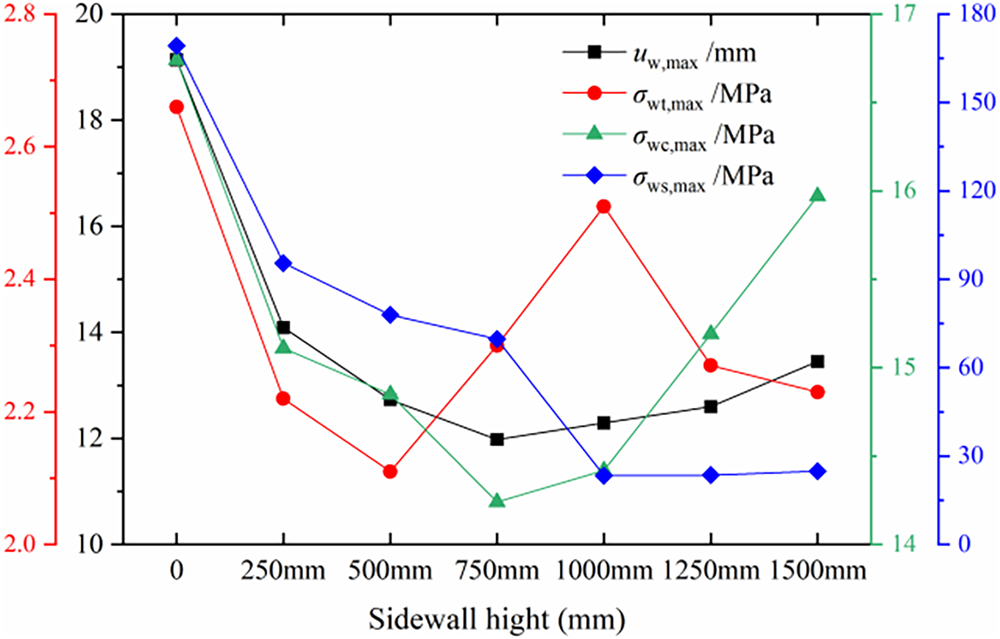
Figure 19: Stress and displacement of the pier box varied with the sidewall heights
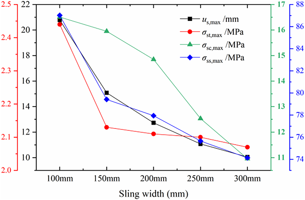
Figure 20: Stress and displacement of the pier box varied with the hoisting sling widths
Table 3 presents the finite element simulation results for Model M1. During the hoisting process, the maximum displacement of the precast concrete pier box was 12.73 mm, located in the middle of the short-side sidewalls (the cantilever portion), as illustrated in Fig. 21a. The maximum tensile stress experienced by the pier box was 2.11 MPa, as shown in Fig. 21b, and was locally concentrated at the bottom center hole. Excluding the localized area of the maximum local tensile stress, as shown in Fig. 21c, the maximum tensile stress was 2.02 MPa. The maximum compressive stress, amounting to 14.85 MPa, was identified at the contact area between the bottom corner of the pier box and the hoisting slings, as indicated in Fig. 21d. Furthermore, Fig. 21e demonstrates that the maximum stress experienced by the reinforcement cage was 77.95 MPa.
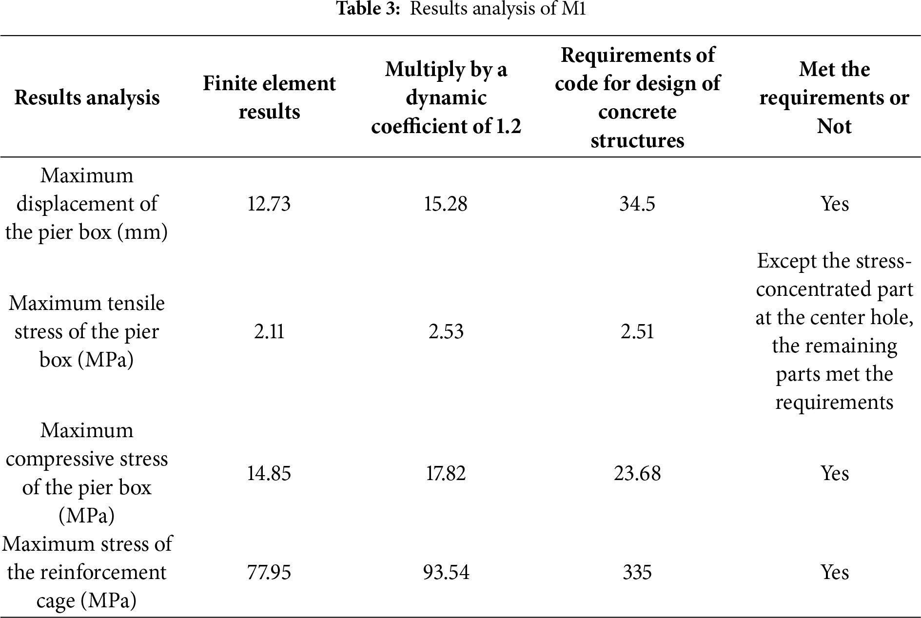
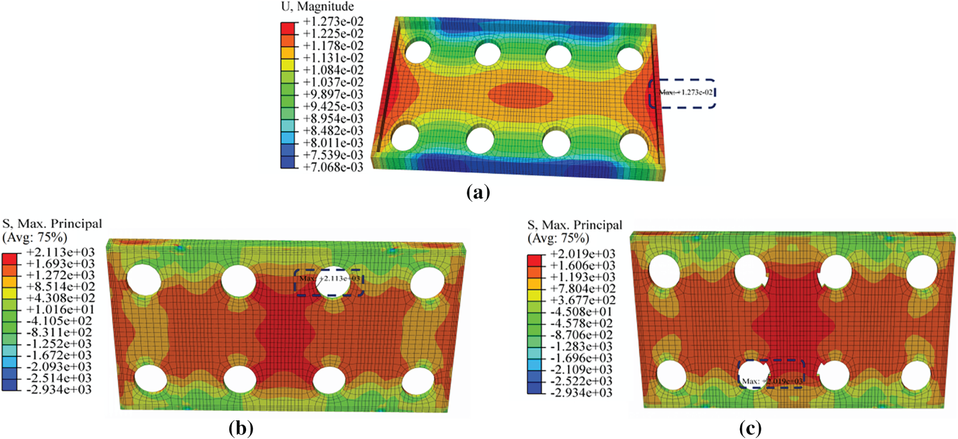
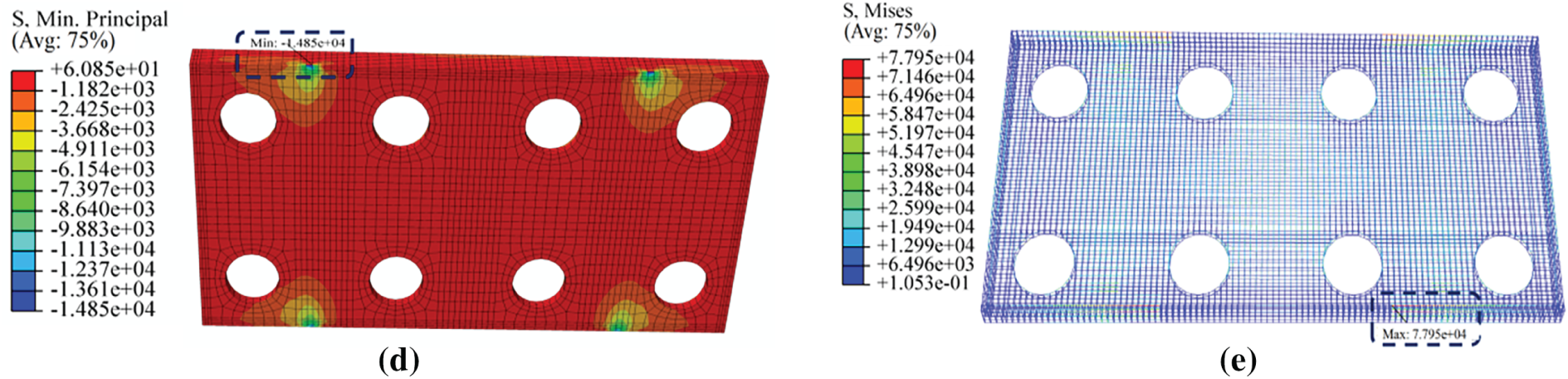
Figure 21: Contour diagrams of M1. (a) Displacement contour diagram of M1; (b) Tensile stress contour diagram of M1; (c) Tensile stress contour diagram of M1 (except the local stress-concentrated part near the center holes); (d) Compressive stress contour diagram of M1; (e) Stress contour diagram of the reinforcement cage of M1
Considering the acceleration response at the moment of hoisting, a dynamic factor of 1.2 was applied, resulting in a maximum displacement of the pier box of 15.28 mm, which satisfied the maximum deflection limit of 29.6 mm calculated according to Code for Design of Concrete Structures [28], as shown in Eq. (1). The maximum tensile stress was measured at 2.53 MPa, slightly exceeding the standard requirement of 2.51 MPa for the axial tensile strength of C45 concrete [28]. The observed stress exceedance is minimal (approximately 0.8%) and highly localized, occurring only in the stress-concentrated region around the center holes, which accounts for less than 0.5% of the total area of the bottom plate. This localized stress concentration is primarily attributable to the geometric discontinuity at the holes. In contrast, the maximum tensile stress in the remaining regions of the pier box is 2.02 MPa, which, after applying the dynamic coefficient of 1.2, becomes 2.42 MPa—a value that remains below the standard limit of 2.51 MPa. Nevertheless, to ensure a sufficient safety margin and strict compliance with the code requirements, further optimization was considered necessary. The maximum compressive stress of the pier box, at 17.82 MPa, complied with the requirement, which is 0.8 times the standard value of the axial compressive strength of C45 concrete, calculated to be 23.68 MPa [26].
In the formula, μlim represents the ultimate deflection value, while l0 represents the calculated span of the concrete pier box.
5 Local Optimization and Hoisting Validation
To mitigate the concentrated stress around the holes in the bottom slab of the pier box, the project implemented symmetrical stiffeners and steel sleeves to provide localized reinforcement. The steel sleeves were anchored to the pier box through the stiffeners, which in the finite element analysis was simplified as a “tie” constraint between the outer walls of the steel sleeves and the inner walls of the holes, effectively simulating the welding connection, as illustrated in Fig. 22.
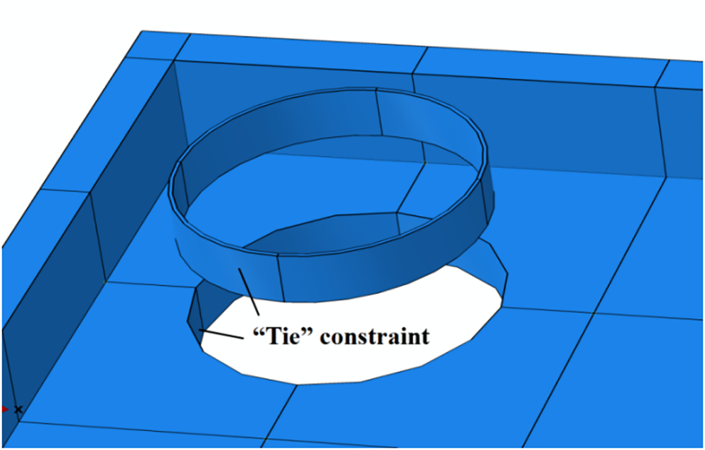
Figure 22: Model of local reinforcement at the holes of the bottom plate
The reinforcement proved highly effective. As summarized in Table 4, the maximum tensile stress of the pier box was reduced to 2.07 MPa, which became 2.48 MPa after applying the dynamic coefficient of 1.2 and was below the axial tensile strength of C45 concrete [26]. Moreover, the critical location of the maximum tensile stress shifted away from the hole periphery, as evidenced by comparing the stress contours in Figs. 21b and 23b, which indicated that the reinforcement successfully alleviated the severe stress concentration at the geometric discontinuity. The stress in the steel sleeves remained low at 44.24 MPa, confirming their structural adequacy, while other structural responses also met code requirements, as shown in Fig. 23.
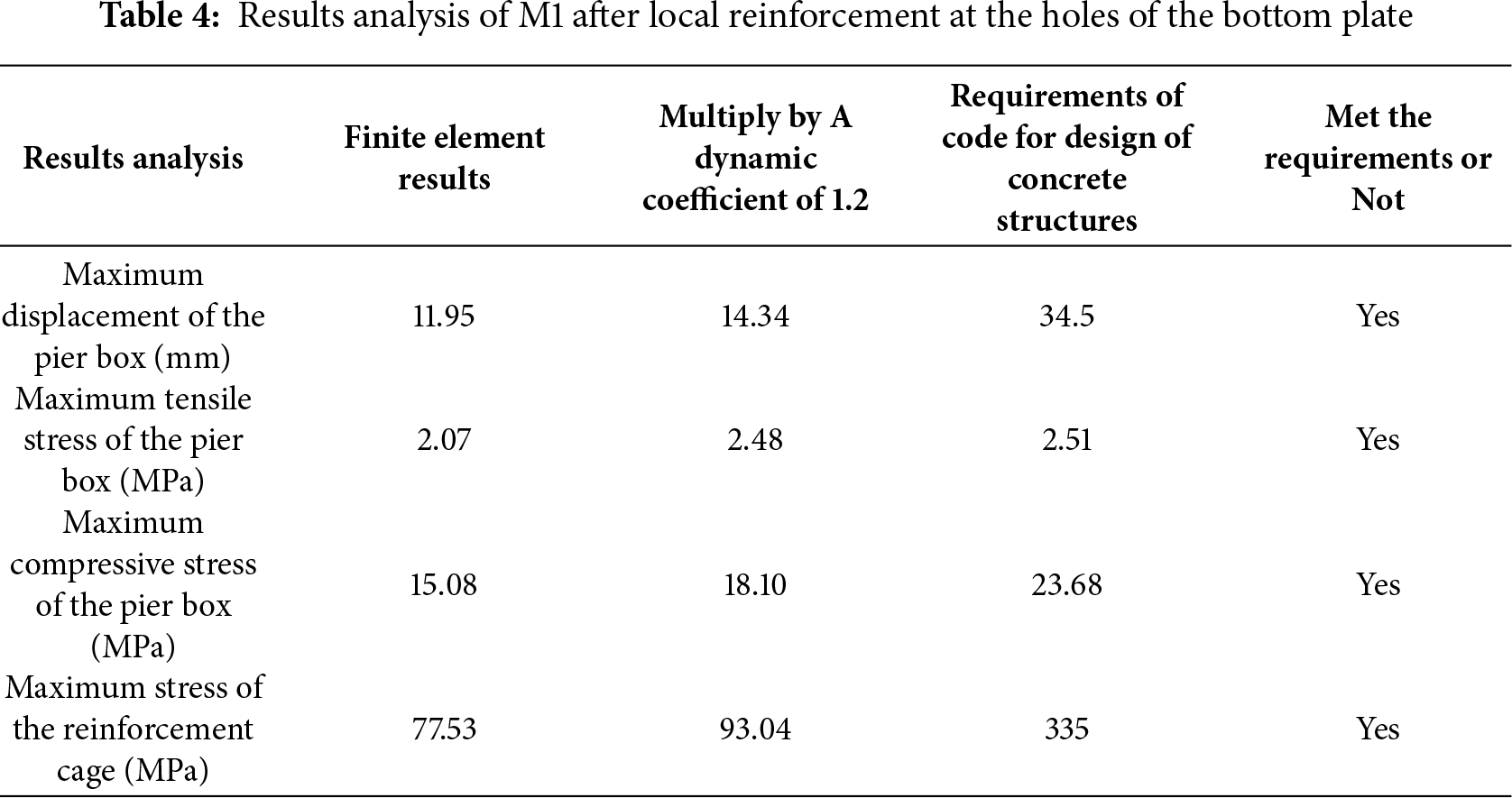
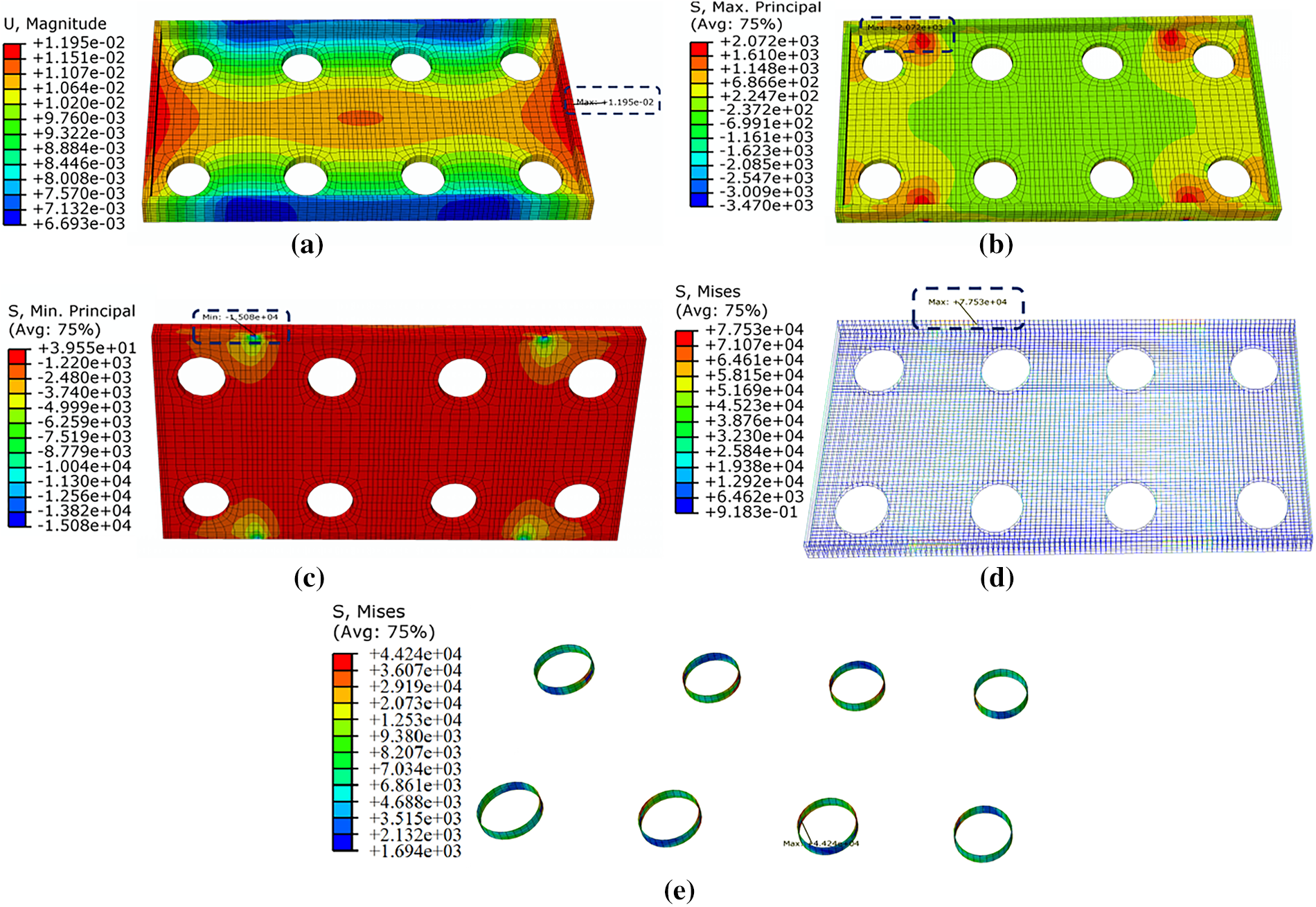
Figure 23: Stress contour diagram of M1 after local reinforcement at the holes of the bottom plate. (a) Displacement contour diagram of the pier box; (b) Tensile stress contour diagram of the pier box; (c) Compressive stress contour diagram of the pier box; (d) Stress contour diagram of the reinforcement cage; (e) Tensile stress contour diagram of the steel sleeves
Field observations conclusively validated these numerical predictions. The precast pier box was successfully hoisted in its entirety without any visible cracking, as documented in Fig. 24, which demonstrated the practical efficacy of the reinforcement measure and confirming the accuracy of the finite element model.
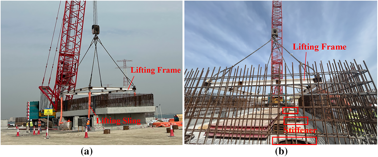
Figure 24: Diagram of on-site hoisting. (a) Overall hoisting; (b) The concrete pier box
This study investigated the hoisting safety of the precast pier box for the 7th and 8th Sea-Crossing Bridges in Abu Dhabi via finite element analysis, with a focus on the effects of sidewall casting height and hoisting sling width. The key findings are summarized as follows.
1. The sidewall height significantly affects the stress and displacement. The absence of sidewalls resulted in the largest displacement and stress, whereas a height of 500 mm was identified as optimal for minimizing the maximum tensile stress. This height provides adequate restraint to the bottom slab without introducing excessive self-weight.
2. Increasing the sling width from 100 to 300 mm reduces both displacement and stress, as a wider sling distributes the load more effectively, mitigating local contact stresses. A sling width of 200 mm (REE-100T) was selected to balance structural safety and cost-effectiveness.
3. Significant stress concentrations were observed around the holes in the bottom slab, where the maximum tensile stress (2.53 MPa after dynamic amplification) slightly exceeded the allowable limit for C45 concrete (2.51 MPa). The implementation of local reinforcement with steel sleeves reduced this stress to 2.48 MPa, achieving code compliance. This numerical result confirms the effectiveness of the reinforcement, which was validated by the absence of cracks during the actual hoisting.
This study demonstrates through finite element analysis that the hoisting safety of the precast concrete pier box is effectively optimized by employing a 500 mm sidewall height and 200 mm wide slings, which together minimize tensile stress and control displacement while maintaining cost-efficiency. The implementation of local reinforcement with steel sleeves further mitigates stress concentrations at holes, ensuring compliance with design codes and preventing cracking during hoisting, as validated by both numerical results and field observations. It should be noted that this study assumed idealized boundary conditions and did not account for environmental factors such as wind loads. Future work should incorporate these dynamic conditions and explore nonlinear material behavior to enhance model robustness, potentially extending the present methodology to the safety assessment of other large-scale prefabricated components in marine environments.
Acknowledgement: Not applicable.
Funding Statement: The authors gratefully acknowledge the financial support from the Professor Scientific Research Start-up Fund of Hezhou University (2025JSQD04), the Special Project in Key Fields of the Guangdong Provincial Department of Education (No. 2023ZDX3106).
Author Contributions: All authors have made substantial contributions to this work. Peijun Xie was primarily responsible for the study conception, data curation, and writing of the original draft. Shoulong Zhang contributed to the conceptualization and to the subsequent reviewing and editing processes. Pengfei Huang’s contributions lay in field validation and manuscript review. Jintuan Zhang took charge of funding acquisition and overall project supervision, while also participating in the review process. All authors reviewed the results and approved the final version of the manuscript.
Availability of Data and Materials: The data used to support the findings of the study are available from the corresponding authors upon request.
Ethics Approval: Not applicable.
Conflicts of Interest: The authors declare no conflicts of interest to report regarding the present study.
References
1. Stith JC, Helwig TA, Williamson EB, Frank KH, Engelhardt MD, Schuh AC, et al. Comparisons of the computed and measured behavior of curved steel I-girders during lifting. J Struct Eng. 2012;138(1):1–10. doi:10.1061/(asce)st.1943-541x.0000417. [Google Scholar] [CrossRef]
2. Holden KM, Pantelides CP, Ries JM, Malan SH. Lifting of GFRP precast concrete bridge deck panels. J Perform Constr Facil. 2015;29(3):04014075. doi:10.1061/(asce)cf.1943-5509.0000563. [Google Scholar] [CrossRef]
3. Chen S, Yin T, Sang X, Ye B, Ding M. Analysis on out-of-plane stability of large-span single space tube truss during hoisting. IOP Conf Ser Earth Environ Sci. 2021;668:10. [Google Scholar]
4. Ruan R, Lai M, Jiang C, Wang J, Lin Y. Integral lifting of steel structure corridor between two super high-rise buildings under wind load. Buildings. 2023;13(10):2441. doi:10.3390/buildings13102441. [Google Scholar] [CrossRef]
5. Hu J, Li P. Integral fabrication and hoisting technology of curved continuous steel box girder. In: Oke SA, AhmatF, editors. Water conservancy and civil construction Volume 1. 1st ed. Boca Raton, FL, USA: CRC Press; 2023. p. 274–80. doi:10.1201/9781003450818-39. [Google Scholar] [CrossRef]
6. Zhang H, Zhou RZ. Research on lifting techniques of large segments of steel box girder of Chongqi Bridge. Adv Mater Res. 2012;446-449:1094–8. doi:10.4028/www.scientific.net/amr.446-449.1094. [Google Scholar] [CrossRef]
7. Sheng X, Zhang H, Bao Y, Ling C. Finite element checking of flange connection in integral hoisting of flare stack. In: Proceedings of the 2016 International Conference on Advanced Electronic Science and Technology (AEST 2016); 2016 Aug 19–21; Shenzhen, China. Paris, France: Atlantis Press; 2016. p. 380–6. [Google Scholar]
8. Liu J. Finite element analysis of the integral hoisting of 49 m flange connection flare. IOP Publ. 2017;281:012049. doi:10.1088/1757-899x/281/1/012049. [Google Scholar] [CrossRef]
9. Duan M, Liao N, Zhang L, Hu X. The mechanical behavior of a long-span steel-box girder during the hoisting process. Vib Proced. 2022;42:52–6. doi:10.21595/vp.2022.22462. [Google Scholar] [CrossRef]
10. David SA, Schexnayder CJ. Hoisting “Y” columns at the Phoenix Airport parking garage expansion. Pract Period Struct Des Constr. 2000;5(4):138–41. doi:10.1061/(asce)1084-0680(2000)5:4(138). [Google Scholar] [CrossRef]
11. Zeng WJ, Yang SQ. Integral hoisting technology of arch rib of concrete filled steel tube arch bridge. Appl Mech Mater. 2013;405–408:3086–9. doi:10.4028/www.scientific.net/amm.405-408.3086. [Google Scholar] [CrossRef]
12. Li HX, Duan LL, Wang XW, Zhu B. Finite element simulation of large segment hoisting construction for Hong Kong-Zhuhai-Macao Bridge. Adv Mater Res. 2014;919–921:551–5. doi:10.4028/www.scientific.net/amr.919-921.551. [Google Scholar] [CrossRef]
13. Cheng H, Xie Z, Zhu Y. Stress analysis of the cable tower during hoisting construction of a self-ascending crane of the Shunde bridge. In: Advances in civil function structure and industrial architecture. 1st ed. Boca Raton, FL, USA: CRC Press; 2022. p. 482–92. [Google Scholar]
14. Cheng X, Sun Y, Hong J. Mechanical characteristics of hoisting construction of segmental cantilever assembled box girder bridge. Eng Res Express. 2024;6(2):025114. doi:10.1088/2631-8695/ad3a35. [Google Scholar] [CrossRef]
15. Xie Z, Kang P, Cui G, Fan X, Deng L. Analysis and construction technology research on unbalanced lifting of prefabricated plate components in prefabricated subway stations. In: Civil engineering and smart structure technology. Amsterdam, The Netherlands: IOS Press; 2025. p. 11–20. doi:10.3233/atde250192. [Google Scholar] [CrossRef]
16. Wang JF, Xiang HW, Zhang JT, Wu TM, Xu RQ. Geometric state transfer method for construction control of a large-segment steel box girder with hoisting installation. J Zhejiang Univ Sci A. 2020;21(5):382–91. doi:10.1631/jzus.a1900213. [Google Scholar] [CrossRef]
17. Wang K, Ma M, Wang J, Yang R, Hu L, Luo Z. Analysis of mechanical behavior of symmetric prefabricated bodies and metal connecting components during hoisting and overturning in assembly structures. Symmetry. 2025;17(2):196. doi:10.3390/sym17020196. [Google Scholar] [CrossRef]
18. Li SG, Li H. Optimization method of hoisting points schemes using strain energy criterion. Appl Mech Mater. 2011;88-89:583–6. doi:10.4028/www.scientific.net/amm.88-89.583. [Google Scholar] [CrossRef]
19. Tian L, Hao J, Wei J, Zheng J. Integral lifting simulation of long-span spatial steel structures during construction. Autom Constr. 2016;70:156–66. doi:10.1016/j.autcon.2016.06.015. [Google Scholar] [CrossRef]
20. Tong Z, He S, Tong S, Han Y, Peng X. Transient simulation and optimization for the integral hoisting of extra-large air separation cold box. Processes. 2023;11(7):2143. doi:10.3390/pr11072143. [Google Scholar] [CrossRef]
21. Ding M, Han S, Wei Y, Ruan Y, Luo B. Non-bracket oblique traction-hoisting construction strategy for cable-truss structures. Heliyon. 2024;10(10):e31502. doi:10.1016/j.heliyon.2024.e31502. [Google Scholar] [PubMed] [CrossRef]
22. Cao XZ, Chen ZF. The influencing factors of the steel lining of the outer containment dome of the nuclear power plant in the hoisting process based on ABAQUS. In: Urban construction and management engineering IV. 1st ed. Boca Raton, FL, USA: CRC Press; 2024. p. 558–62. [Google Scholar]
23. Song Q, Deng W, Liu D, Pei H, Peng Z, Zhang J. Optimal design of segment storage and hoisting of precast segmental composite box girders with corrugated steel webs. Buildings. 2023;13(3):801. doi:10.3390/buildings13030801. [Google Scholar] [CrossRef]
24. Yu X. A construction process for hoisting, precise positioning and temporary fixation of a steel-concrete composite segment on a long-span steel-concrete hybrid girder. Acad J Archit Geotech Eng. 2023;5(3):43–8. doi:10.25236/ajage.2023.050306. [Google Scholar] [CrossRef]
25. JGJ 276-2012. Code for safety of hoisting and lifting in construction. Beijing, China: China Architecture Publishing & Media Co., Ltd.; 2012. (In Chinese). [Google Scholar]
26. GB 50666-2011. Code for construction of concrete structures (English version). Beijing, China: China Architecture Publishing & Media Co., Ltd.; 2011. [Google Scholar]
27. Jian Feng Sling CO., LTD. Jian Feng Synthetic Lifting and Lashing. Guangzhou, China. [cited 2018 June 4]. Available from: http://www.jian-feng.com/page84.html. [Google Scholar]
28. GB 50010-2010. Code for design of concrete structures (English version). Beijing, China: China Architecture Publishing & Media Co., Ltd.; 2010. [Google Scholar]
29. Timoshenko S, Woinowsky-Krieger S. Theory of plates and shells. 2nd ed. Columbus, OH, USA: McGraw-Hill; 1959. [Google Scholar]
30. Bažant ZP. Size effect in blunt fracture: concrete, rock, metal. J Eng Mech. 1984;110(4):518–35. doi:10.1061/(asce)0733-9399(1984)110:4(518). [Google Scholar] [CrossRef]
31. Jin L, Wang T, Du X, Xia H. Size effect theory on shear failure of RC cantilever beams. Eng Mech. 2020;37(1):53–62. (In Chinese). [Google Scholar]
Cite This Article
 Copyright © 2026 The Author(s). Published by Tech Science Press.
This work is licensed under a Creative Commons Attribution 4.0 International License , which permits unrestricted use, distribution, and reproduction in any medium, provided the original work is properly cited.
 Downloads
 Citation Tools