
 Submit a Paper
 Propose a Special lssue
 Open Access
REVIEW
Analytical Models of Concrete Fatigue: A State-of-the-Art Review
1
College of Civil Engineering, Tongji University, Shanghai, 200092, China
2
Department of Civil Engineering, Minia University, EL-Minia, 61111, Egypt
* Corresponding Author: Xiaodan Ren. Email:
Computer Modeling in Engineering & Sciences 2023, 134(1), 9-34. https://doi.org/10.32604/cmes.2022.020160
Received 08 November 2021; Accepted 22 February 2022; Issue published 24 August 2022
 View Full Text
 Download PDF
Abstract
Fatigue failure phenomena of the concrete structures under long-term low amplitude loading have attracted more attention. Some structures, such as wind power towers, offshore platforms, and high-speed railways, may resist millions of cycles loading during their intended lives. Over the past century, analytical methods for concrete fatigue are emerging. It is concluded that models for the concrete fatigue calculation can fall into four categories: the empirical model relying on fatigue tests, fatigue crack growth model in fracture mechanics, fatigue damage evolution model based on damage mechanics and advanced machine learning model. In this paper, a detailed review of fatigue computing methodology for concrete is presented, and the characteristics of different types of fatigue models have been stated and discussed.Keywords
It is inevitable for concrete structures to bear fatigue loads during their lifetime. With the development of material science and technology, the fatigue stress level acting on concrete gradually increases. Due to the high amplitude and frequency of fatigue loads, the fatigue problem is prominent, particularly on new concrete structures such as wind power towers, offshore platforms, and high-speed railways. For example, Fig. 1 shows that the reinforced concrete foundation of a wind turbine tower cracked due to long-term fatigue loads. In order to ensure safety, the research on fatigue of concrete is of vital importance in structural engineering. Over the past century, significant and considerable efforts have been made to develop analytical and numerical methods for concrete fatigue. Tests show that a number of loading cycles will lead to structural failure due to energy dissipation with each loading cycle, and there are hysteresis loops in the stress-strain curve, as shown in Fig. 2. The fatigue life

Figure 1: The destroyed foundation of a wind turbine tower under long-term fatigue loads

Figure 2: The energy dissipation under fatigue loading
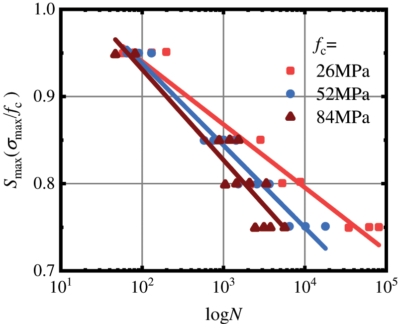
Figure 3: The relationship between the fatigue life and the stress level (data from literature [1])

Figure 4: The variation trend of concrete response under the fatigue load (data from literature [1])
This research is organized as follows. Some experimental fatigue models, including S − N curves and empirical failure criteria, are presented in Section 2. The solid mechanics models for studying concrete fatigue, which can be divided into fracture mechanics and damage mechanics are discussed in Sections 3 and 4, respectively. The application of machine learning to concrete fatigue research is briefly introduced in Section 5. Finally, Section 6 summarizes some conclusions. In the following sections, the characteristics of every fatigue analysis model for concrete will be illustrated and discussed in detail.
2 Empirical Models Based on Experiments
In general, experimental research has been used to investigate any engineering phenomena. Since the importance of structural fatigue has been recognized, fatigue tests have been carried out, and some empirical models to reflect the fatigue laws of concrete have been established. In 1870, after a systematic study on the fatigue failure of a train wheel, Wöhler[2] proposed Wohler’s law, which reflects the relationship between the stress level S and the number of load cycles N, which is known as the S − N curve. Accordingly, many fatigue tests of concrete were carried out by researchers, and the S − N curves of concrete were fit based on the test data. The earliest concrete compression fatigue test can be traced to the early 20th century[3,4]. Since the 1970s, experimental research on the fatigue performance of concrete under uniaxial compression has been systematically explored. In 1973, a formula of compression S − N curves for concrete was proposed by Aas-Jakobsen etal. [5] and modified by Tepfers etal. [6] as a linear relationship in the semilogarithmic coordinate system, and it was expressed as follows:
where fatigue strength S is the ratio of the maximum stress
On this basis, the effect of loading rate on the fatigue life of concrete was noted and studied[9–11]. It was indicated that with the increase of loading rate, the fatigue life of concrete at a certain stress level would increase. In order to consider the rate effect on fatigue performance, the loading period T was introduced into the expression of Eq. (1) by Hsu etal.[10], and the different expressions of high-cycle fatigue and low-cycle fatigue were expressed as follows:
• High cycle fatigue (
• Low cycle fatigue (1 cycle
The parameters in Eqs. (2) and (3) have been taken as the exact meanings of the original formula in Eq. (1).
In addition, the research on the compression fatigue performance of high-strength concrete indicated that the fatigue strength would decrease with the increase of the static strength[1,12–14]. Based on test results, a formula for S − N relationship considering concrete strength was proposed by Kim[1]:
where
Owing to the significant difference between the tensile and compressive characteristics of concrete, the experiments of tensile fatigue were performed through the indirect splitting test[15] and the direct tensile test[16–18]. It is more complex to carry out the tension fatigue tests of concrete than compression fatigue tests because the eccentricity of loading in pulse tension test is easy to occur, which is difficult to deal with even for static loading. Moreover, special test equipment and specimen shape are required in the tension test. Thus, the results of tensile fatigue tests are relatively small. In 1979, the same formula of the tension S − N curves as Eq. (1) was obtained by Tepfers[15] through splitting tensile test, in which the parameter
• Tension fatigue (
• Compression-tension fatigue (
where ft and fc are the static tensile strength and the static compressive strength of concrete, respectively.
In practice, materials are probably subjected to a multi-dimensional stress. The current test research of the multi-dimensional fatigue loading is relatively scarce. In this regard,the biaxial fatigue tests have been performed and presented[19,20], besides the axial fatigue testes with lateral confinement [21–26]. It could be observed that the compressive fatigue strength of concrete would increase while the tensile fatigue strength would decrease under lateral confinement. In addition, the expression of the S − N curves with lateral confinement was given by Hooi[21] as follows:
in which
In order to consider the great discreteness and randomness of concrete fatigue life, the fatigue strength under a certain failure probability P was studied in the statistical probability method [27]. The empirical S − N − P relationships between stress level (S), number of cycles (N), and failure probability (P) were fitted[28–30]. In addition, fatigue tests of new materials, such as high-strength concrete[1,31], fiber-reinforced concrete[32], recycled aggregate concrete[33], and so on, also were carried out. It is worth noting that the main objective of the early research on concrete fatigue was to obtain the quantitative relationship between fatigue life and fatigue stress by several tests. Indeed, it’s convenient to calculate the fatigue life under a given stress level with S − N curves. Due to the large discreteness of concrete fatigue experiments, a large number of experiments are needed to obtain the S − N curves. However, most of the conclusions obtained are inadequate to cover all the different cases, particularly in the complex stress field; no unified conclusion is universally accepted.
2.2 Empirical Fatigue Failure Criteria
In order to give an index to judge fatigue failure, some phenomenal fatigue damage accumulation models are developed. It is assumed that damage is accumulated linearly with the number of the load cycles, and the fatigue damage D is defined as the sum of the ratio of the load cycles Ni to the fatigue life
in which C represents the C-th fatigue stress level, and Ni and

Although the improved P − M rules consider the nonlinearity of damage accumulation associated with the loading history, it is still limited to concrete material and difficult to extend to fatigue prediction of the whole structure. The premise of using the P − M rule is that the ultimate fatigue life
It can be concluded that the fatigue research presented in this section is focused on the fatigue performance of concrete material level. Also, several types of research have been carried out on the fatigue of the concrete beams [47–55] and slabs[56,57]. Structural fatigue is affected by many factors, such as reinforcement ratio, shear span ratio, concrete strength, and so on. Only some qualitative conclusions were drawn, and there are no united and universal design standards for fatigue of concrete structures. The limit state method or the allowable stress method are still used for the design of concrete structures subjected to fatigue loads, which means that stress redistribution during loading cannot be considered.
3 Fracture Mechanics-Based Fatigue Models
This section introduces the application of fracture mechanics methods in concrete fatigue. Due to the fact that the concrete is a complex composite material, the micro-cracks are initiated and propagated during the curing process. Consequently, the expansion and accumulation of these micro-cracks under fatigue loading lead to the generation of macro-cracks, which causes fatigue fracture of concrete. Thus, the theories of fracture mechanics describing crack propagation were initially introduced to investigate the growth of the fatigue crack. The more commonly used methods include Paris’ law and the cohesive crack model.
3.1 The Modified Paris’ Law for Concrete
Paris’ law based on linear elastic fracture mechanics gives the fatigue growth rate at the crack tip. In 1962, a formula describing the propagation rate of fatigue crack was proposed by Paris etal.[58], known as Paris’ law, and it was expressed as follows:
where a represents the crack length, N is the number of cyclic loads,
in which
where
It is found that the growth of fatigue cracks could also be affected by the concrete specimens sizes [49,69,70]. The size effect on the crack growth was studied in [69,70], and a size-adjusted Paris’ law was proposed as follows:
where KIc is the size-adjusted fracture toughness, KIf is the asymptotic value of fracture toughness for an infinitely large specimen, d is the depth of the specimen, and d0 is a constant characterizing the specimen geometry. Compared to Eq. (9), a normalized stress intensity factor was adopted in the size-adjusted Paris’ law, and the normalization rule is related to the size of the specimen. Then,the discoveries of Kolluru etal. [71–73] were that the crack growth rate decreased first and then increased. The critical crack length where the rate of crack growth changed from deceleration to acceleration was the crack length at the peak load of the quasi-static response. Two mechanisms governing the crack growth rate were assumed: the crack growth is governed by the increasing resistance in the deceleration stage, and the Mode I stress intensity factor
• In the deceleration stage (a <acrit)
• In the acceleration stage (a ≥ acrit)
where acrit is the critical length at the peak load of the quasi-static response,
Since concrete is a composite complex material, the path and shape of concrete crack surface are random when concrete material cracks. Therefore, some fractal theories and self-similarity methods were introduced to explain the propagation of the fatigue crack and improve the Paris’ law [74–76]. However, it was only an approximation means, and there was minor progress in promoting the modified Paris’ law to apply to the concrete fatigue crack.
It should be noted that Paris’ law is concerned with the existing small cracks, in which the crack initiation cannot be considered. Because the stress intensity factor is only applicable to the near-tip zone of the crack, the use of the linear elastic fracture mechanics requires that the crack zone be very small compared with the dimensions of the specimen. With the crack propagation, the stress intensity factor is no longer dominant.
3.2 The Cohesive Fatigue Crack Models
It is generally believed that the nonlinearity of concrete crack tip should be considered. In the 1970s, the fictitious crack model was proposed first by Hillerborg etal. [77] to reflect the nonlinear characteristics of materials in the fracture process. The fictitious crack model, which is also usually called the cohesive crack model, contributes to using the finite element method in complex fracture problems. A certain number of assumptions had been made to apply the cohesive crack model to fracture analysis of concrete material [78,79]. Firstly, it is assumed that a fracture zone can transfer traction at the crack tip. Secondly, it is assumed that before the ultimate strength of the material is reached, the concrete is elastic, and if the principal tensile stress exceeds the ultimate strength, the concrete materials start to crack, and the tensile stress also starts to decrease. The stress transfer ability depends on the crack opening displacement

Figure 5: (a) The curve of
Initially, the cohesive crack model was mainly used for the cracking process under monotonic loading. The cohesive crack model was first used to explain qualitatively how fatigue crack extends and how the stress at the tip changes by Reinhardt [80], illustrated as Fig. 6. Assume a crack with length a(N) after N loading cycles, and the softening zone c(N) has developed in front of the crack, as shown in Fig. 6a. After the external force is completely released, the part with too large strain cannot be completely recovered. The stress at the crack tip will not disappear but remains self-equilibrium, as shown in Fig. 6b. During the next loading cycle, the stress in the softening zone reduces due to the influence of unloading, and the softening zone should spread a little in order to ensure equilibrium, as shown in Fig. 6c. In a following cycle, the same procedure is repeated, and the softening zone will extend forward, as shown in Figs. 6d and 6e. Along this simple physical model, the stress-COD envelopes and the hysteresis relationships were needed for the numerical simulations. For example, a trilinear stress-strain envelope and the straight-line unloading-reloading paths in each stage, as shown in Fig. 7, were assumed by Gylltoft [81] to simulate the progressive fracture of the notched beams of plain concrete subjected to cyclic loading. However, this is inadequate to describe more failure modes.

Figure 6: Fatigue crack growth of quasi-brittle material during cyclic loading [80]

Figure 7: The model of fatigue stress-crack opening displacement by Gylltoft
In order to obtain better stress-COD curves, monotonic loading and cyclic loading tests were carried out [82,83]. The widely used expression of the
where c1 and c2 are constants. In addition, a detailed focal point model describing the path of unloading and reloading was proposed by Yankelevsky and Reinhardt [83] based on the observations of stiffness changes in a specific cycle, as shown in Fig. 8. In this model, multiple lines were used to specify the relationship between stress and crack opening displacement at the crack tip during the process of loading-unloading-reloading. The focal model presents a cyclic approach which is closer to the actual behavior. Since the construction of the focal model needs to follow the complex rules to determine many special points, it is inconvenient for the implementation of the finite element analysis. Assume that the curve during an unloading-reloading cycle would not return to the same point of the envelope curve where it started to unload but to a point with lower stress, and the gap between the unloading point and the returned point can be explicitly given. The four expressions for cyclic
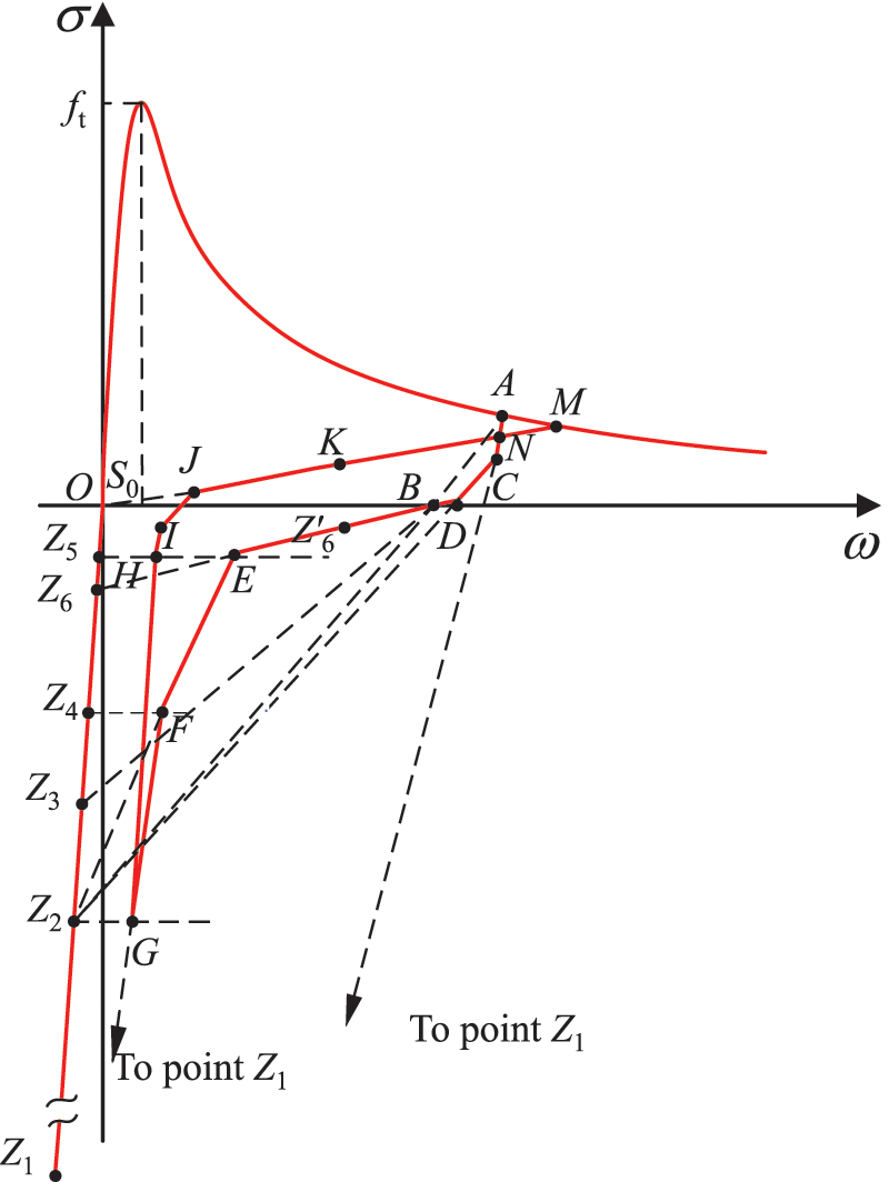
Figure 8: The focal model by Yankelevsky and Reinhardt

Figure 9: The Hordijk’s model
Due to the complexity of the hysteretic model and the time-consuming in finite element analysis, the fatigue constitutive relationship of the crack tip had been simplified [85,86]. For example, the unloading-reloading path in the mentioned Hordijk’s model was simplified as three straight lines in [86].
Based on the mentioned nonlinear fracture mechanics-based models, it can be indicated that nonlinear fracture mechanics could explain the process of concrete fatigue crack growth in detail. The fracture mechanics model was mainly used to analyze the fatigue growth characteristics of one or a few macro-cracks in members. In the finite element analysis, the cohesive elements must be set in advance along the fracture zone. The nonlinear property is used in the element of the fracture zone with the dense discretization, while the linear property is still used in the main body. But, there are many initial micro-cracks and micro-defects in the concrete’s interior. The cohesive crack model is difficult to describe the propagation and aggregation process of a large number of randomly distributed micro-cracks under the fatigue load.
4 Damage Mechanics-Based Fatigue Models
From the test results [14,87,88], the response of concrete under fatigue loading has obvious three-stage characteristics. For example, the total strain growth of concrete under constant amplitude fatigue load can be divided into three stages: the rapid increase at the first 10% of life, the stable development during the

Figure 10: Increase of the compression strain with loading cycles

Figure 11: Degradation of the elastic modulus with loading cycles
As a branch of solid mechanics, damage mechanics is mainly used to study the degradation of macro-mechanical properties of material caused by the generation and expansion of internal micro-defects. This section reviews the development of fatigue damage theories.
In the damage mechanics, the constitutive equation can be expressed as:
Damage variable
where f is the gauge function. According to the orthogonal flow criterion, the evolution of the damage variable can be taken as follows:
where
Eq. (21) indicates that when the stress state isn’t beyond the damage surface, the damage will not increase regardless of the external loads change. Fatigue load can be divided into low cycle fatigue and high cycle fatigue loads according to the number of load cycles. The low cycle hysteretic behavior of structures under seismic loads has been easily obtained using the general damage model [90–92] or the construction of the hysteretic constitutive model [93 –95]. This section pays attention to the models for concrete structures under high-cycle fatigue loads. The stress state under high-cycle fatigue loading might always be within the damage surface, which means that there is always no damage evolution if the static damage model is adopted. Actually, fatigue loads could lead to damage accumulation of concrete even if the stress state is lower than the damage surface. When the hysteretic energy dissipation accumulates to a certain level, the structure will fail. Therefore, when it comes to the performance of structures under high cycle fatigue loads, the static model no longer has good predictability. To overcome the drawbacks of the conventional damage criterion, there are two approaches to solve the accumulation of fatigue damage. One is the bounding surface theory [96–98], and the other is fatigue loading-unloading criterion [99,100].
In the bounding surface theory [97], a limit fracture surface (LFS), a boundary surface (BS), and a loading surface (LS) changing with loading history were defined, as shown in Fig. 12. The damage begins to increase only when the loading surface under fatigue loading is outside the limit fracture surface and expands towards the direction of the boundary surface. The damage growth rate is related to the distance between a point on the loading surface and the corresponding mapping point on the boundary surface. In finite element calculations, many iterations and corrections are required, which will be time-consuming.

Figure 12: The limit fracture surface, the boundary surface, and the loading surface in Suaris’ model
The fatigue loading-unloading criterion was proposed by Marigo [99] to judge whether fatigue damage evolves or not. The loading-unloading irreversibility concept not only can capture the damage accumulation within the damage surface but also is simple to apply. This concept means that the internal fatigue damage variables of concrete only increase in the rising stage of every load cycle. Interestingly, there are similar models in the study of the fatigue response of other materials [101]. Here, the damage consistency parameter was directly expressed as:
where
For a complete damage constitutive relationship, reasonable fatigue damage evolution laws are also very significant. The form of damage variable can be divided into the single scalar damage [102–107] and the anisotropic tensor damage [100,108–112]. The evolution of the single scalar damage under high-amplitude and low-cycle fatigue loading can be simply calibrated by the tests and accurately simulate the uniaxial hysteretic behavior of concrete [104,105,113]. The single scalar damage models are weak to reproduce fatigue response of concrete structures subjected to the high-cycle and low-amplitude fatigue loads, as well as multiaxial stress. Actually, the anisotropic damage model is more consistent with the anisotropic mechanical properties of concrete. The earliest anisotropic fatigue damage model for concrete was extended by Papa et al. [100] from the anisotropic static damage model. The total damage was decomposed into a second-order symmetric damage tensor D in deviatoric strain space and a scalar damage variable d in volumetric strain space. The evolutions for each component of damage are as follows:
and,
in which the sign “
It is assumed that the fatigue damage of concrete is mainly driven by tensile strain, and the evolution rate of the fatigue damage tensor was expressed in [108] as follows:
where n, K, and C1 are the material parameters,
Some bi-scalar elastoplasticity fatigue damage models for concrete were extended [109–111] in the frame of the static damage model [114–116]. In the bi-scalar damage model, the effective stress is split into positive and negative parts. The positive part is tension, and the negative part is compression. An isotropic scalar damage is assumed in the tension and compression space. Thus, the anisotropic damage is mapped into two isotropic spaces by the mapping tensors as follows:
in which
where
where
where
in which Es is the inherent energy of the representative volume element, Ef is the fatigue energy dissipation,
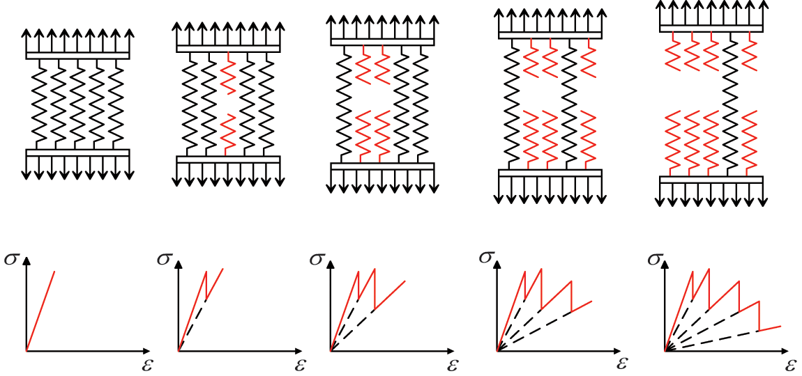
Figure 13: The stochastic fracture model with the spring bundle [115]
At present, the finite element analysis of the low cycle fatigue response of concrete structures can be easily realized. However, the number of cycles of fatigue load acting on a concrete structure sometimes is so large that it would undoubtedly lead to a huge amount of calculation to calculate the fatigue damage accumulation by the cycle-by-cycle integration in the finite element analysis. Therefore, an efficient numerical algorithm is important to realize the simulation for concrete structures under fatigue loading. Some algorithms, such as the cycle jumping algorithm [120–123], the dual temporal scales algorithm [109,124], and the temporal homogenization model [125,126], had been developed to simulate the fatigue process for concrete in a shorter time. Besides, research on various acceleration algorithms is still under exploration, and other algorithms such as the reduced-order modeling algorithm [127] also might attract the attention in the future to be introduced into the accelerated fatigue analysis of concrete.
The great advantage of applying the continuous damage mechanics to studying fatigue constitutive model of concrete is that it accounts for the nonlinear property on the material level without explicitly modeling micro-cracks in advance. The distribution of mechanical degradation in the fatigue process can be depicted by damage variables in the finite element analysis. Since the physical mechanism of concrete damage is not clear, a unified connection has not been established between the evolution of the quasi-static damage and the fatigue damage. To perform the refined analysis of the whole process of structural fatigue in practical engineering, it is required not only a detailed description of the fatigue properties of engineering materials but also the support of appropriate analysis methods and effective calculation techniques.
Machine learning has been utilized to predict the performance of materials or structures in civil engineering [128–136]. Due to the high uncertainty, the fatigue loading of concrete is a random process affected by many factors, such as loading period, specimen size, and environment. The deterministic fatigue models may not cover the combined effects of various factors that affect the fatigue resistance of concrete. Machine learning techniques can overcome the inherent limitation in conventional computing models.
Artificial neural networks (ANN), as a machine learning technique, are commonly used to estimate the fatigue life or fatigue strength of concrete, considering the material and dimensional properties of the test specimens and loading conditions. In ANN, there are three layers of neurons, namely input, hidden, and output layers. Each neuron of the hidden layer is connected to the neurons in the subsequent and previous layer by directed synapses with variable weights, as shown in Fig. 14. The hidden layer can be regarded as the regression module. The collected test data is input for training, and the prediction data can be output after the regression module. From Eq. (1), there are four quantities to determine the S − N curve, the compressive strength fc, themaximum stress σmax, the minimum stress σmin, and the ultimate loading cycles Nf. In [137], the database has been utilized from the published test literature, and the inputs were fc, σmin, and the ultimate loading cycles Nf. Through training, validation, and testing of the neural network, the maximum fatigue strength σmax was predicted as the output. It shows that the prediction accuracy is higher than the S − N expressions recommended in the codes. Other researches have been presented in this field. For example the material properties, dimensions, and loading conditions of components have been considered as inputs, and the fatigue life N − S as outputs is predicted after training of the neural network [138–142]. Moreover, machine learning is also a good option to estimate the fatigue failure reliability of structures [143–145].

Figure 14: The example of an ANN
Deep learning models have achieved remarkable results in image recognition. It is indicated that deep learning models such as the convolutional neural network (CNN), can be applied in crack detection and localization for concrete structures [146–148]. There are many CNN architectures which have been recently applied to crack and damage detection of concrete structures, such as AlexNet [149], ResNet [150], VGG [151], and so on. The general CNN architecture consists of five main layers of the neural network, including input, convolution, pooling, fully connected, and output layers, as shown in Fig. 15. The image data is input through the input layers, and the predicted results are stored in the output layers. The main objective of the convolution layers is to extract features in an image input with a convolution operator. The pooling layers are connected behind the convolution layers, and the purpose of introducing them is to simplify the output of the convolution layers. The fully connected layers are to take the output of the previous layer (i.e., the pooling layer) and then apply weights to predict the correct results. Besides, some auxiliary layers, such as dropout and batch normalization (BN) layers, can be added according to the research needs. It can be seen that automatic crack and damage detection with deep learning can help to evaluate the fatigue performance of structures in time in the future, although there are few applications at present. Furthermore, some deep learning models, such as AlexNet, GoogLeNet, ResNet, can also be implemented to mechanical property estimation through analyzing microscopic images in nondestructive testing [152].

Figure 15: The general CNN architecture
Machine learning is expected to be a tool to interpolate or predict more results based on the limited experimental or finite element computational data without burden such as economy or computational time. At the same time, it is possible to realize the automatic structural performance detection by the crack identification function of deep learning. It can better serve the fatigue design of concrete to combine machine learning methods and conventional computing models. However, there is more work to be done across the field of concrete fatigue.
In this study, the development of fatigue analytical models of concrete is presented and discussed. According to this review, it can be concluded that:
• The research on concrete fatigue mainly includes experimental study, research on the crack growth, analysis of whole process response, and prediction using machine learning.
• The early experimental research results provide a certain basis for engineering life prediction; however, the empirical relationships between fatigue life and stress level obtained by the regression of experimental data obviously could not meet modern engineering needs.
• Based on fracture mechanics research, the fatigue model can limitedly reflect the physical mechanism of single crack growth under fatigue loading. However, it was difficult to describe the effect of several randomly distributed microcracks in concrete under complex stress.
• The damage-based fatigue models for concrete can realize the analysis of the whole process of concrete structures under fatigue loading. It can also be used to study the randomness of fatigue of the concrete structures.
• Machine learning provides a new idea for developing a fatigue prediction model of concrete.
• At present, the exploration of concrete fatigue analysis models and calculation methods which can be applied to practical engineering design faces great challenges, and further studies still need to be performed.
Acknowledgement: The authors wish to express their appreciation to the reviewers for their helpful suggestions, which greatly improved the presentation of this paper. Additionally, the second author wishes to appreciate the support from the Chinese Scholarship Council (CSC) under the Joint (Executive Program between Egypt and China (Program (2019–2023)).
Funding Statement: This work was supported by the National Natural Science Foundation of China (Grant Nos. 52078361 and 51678439) and Innovation Program of Shanghai Municipal Education Commission (Grant No. 2017-01-07-00-07-E00006).
Conflicts of Interest: The authors declare that they have no conflicts of interest to report regarding the present study.
References
1. Kim, J. K., Kim, Y. Y. (1996). Experimental study of the fatigue behavior of high strength concrete. Cement and Concrete Research, 26(10), 1513–1523. DOI 10.1016/0008-8846(96)00151-2. [Google Scholar] [CrossRef]
2. Wöhler, A. (1870). Über die festigkeitsversuche mit eisen und stahl. Ernst and Korn, 20, 73–106. [Google Scholar]
3. Graf, O., Brenner, E. (1934). Experiments for investigating the resistance of concrete under often repeated compression loads. Bulletin No. 76, Deutscher Ausschuss für Eisenbeton, 76(83), 17–25+45–53 (in German). [Google Scholar]
4. Bennett, E. W., Muir, S. E. J. (1967). Some fatigue tests of high-strength concrete in axial compression. Magazine of Concrete Research, 19(59), 113–117. DOI 10.1680/macr.1967.19.59.113. [Google Scholar] [CrossRef]
5. Aas-Jakobsen, K., Lenschow, R. (1973). Behavior of reinforced columns subjected to fatigue loading. ACI Journal Proceedings, 70(3), 199–206. DOI 10.14359/11198. [Google Scholar] [CrossRef]
6. Tepfers, R., Kutti, T. (1979). Fatigue strength of plain, ordinary, and lightweight concrete. ACI Journal Proceedings, 76(5), 635–652. DOI 10.14359/6962. [Google Scholar] [CrossRef]
7. Park, Y., Ang, A. H., Wen, Y. K. (1985). Seismic damage analysis of reinforced concrete buildings. Journal of Structural Engineering, 111(4), 740–757. DOI 10.1061/(ASCE)0733-9445(1985)111:4(740). [Google Scholar] [CrossRef]
8. Wang, R. M., Zhao, G. F., Song, Y. P. (1991). Fatigue of plain concrete under compression. China Civil Engineering Journal, 24(4), 38–47 (in Chinese). [Google Scholar]
9. Sparks, P. R., Menzies, J. B. (1973). The effect of rate of loading upon the static and fatigue strengths of plain concrete in compression. Magazine of Concrete Research, 25(83), 73–80. DOI 10.1680/macr.1973.25.83.73. [Google Scholar] [CrossRef]
10. Hsu, T. T. (1981). Fatigue of plain concrete. ACI Journal Proceedings, 78(4), 292–305. DOI 10.14359/6927. [Google Scholar] [CrossRef]
11. Zhang, B., Phillips, D. V., Wu, K. (1996). Effects of loading frequency and stress reversal on fatigue life of plain concrete. Magazine of Concrete Research, 48(177), 361–375. DOI 10.1680/macr.1996.48.177.361. [Google Scholar] [CrossRef]
12. Chimamphant, S. D. (1989). Bond and fatigue characteristics of high-strength cement-based composites (Ph.D. Thesis). New Jersey Institute of Technology, Newark, New Jersey. [Google Scholar]
13. Petkovic, G., Lenschow, R., Stemland, H., Rosseland, S. (1990). Fatigue of high-strength concrete. ACI Special Publication, 121, 505–525. [Google Scholar]
14. Wu, P., Zhao, G., Bai, L. (1994). Fatigue behavior of high strength concrete under compressive cyclic loading. China Civil Engineering Journal, 27(3), 33–40 (in Chinese). [Google Scholar]
15. Tepfers, R. (1979). Tensile fatigue strength of plain concrete. ACI Journal Proceedings, 76(8), 919–934. DOI 10.14359/6969. [Google Scholar] [CrossRef]
16. Saito, M., Imai, S. (1983). Direct tensile fatigue of concrete by the use of friction grips. ACI Journal Proceedings, 80(5), 431–438. DOI 10.14359/10867. [Google Scholar] [CrossRef]
17. Lv, P., Song, Y., Li, Q. (2002). Fatigue tests and damage model of concrete under axial tension. Chinese Journal of Hydraulic Engineering, 33(12), 79–84 (in Chinese). [Google Scholar]
18. Cornelissen, H. A., Reinhardt, H. W. (1984). Uniaxial tensile fatigue failure of concrete under constant-amplitude and programme loading. Magazine of Concrete Research, 36(129), 216–226. DOI 10.1680/macr.1984.36.129.216. [Google Scholar] [CrossRef]
19. Su, E. C., Hsu, T. T. (1988). Biaxial compression fatigue and discontinuity of concrete. ACI Materials Journal, 85(3), 178–188. DOI 10.14359/3546. [Google Scholar] [CrossRef]
20. Lan, S., Guo, Z. (1999). Biaxial compression behavior of concrete under repeated loading. Journal of Materials in Civil Engineering, 11(2), 105–115. DOI 10.1061/(ASCE)0899-1561(1999)11:2(105). [Google Scholar] [CrossRef]
21. Hooi, T. T. (2000). Effects of passive confinement on fatigue properties of concrete. Magazine of Concrete Research, 52(1), 7–15. DOI 10.1680/macr.2000.52.1.7. [Google Scholar] [CrossRef]
22. Taliercio, A. L., Gobbi, E. (1996). Experimental investigation on the triaxial fatigue behaviour of plain concrete. Magazine of Concrete Research, 48(3), 157–172. DOI 10.1680/macr.1996.48.176.157. [Google Scholar] [CrossRef]
23. Taliercio, A. L., Gobbi, E. (1997). Effect of elevated triaxial cyclic and constant loads on the mechanical properties of plain concrete. Magazine of Concrete Research, 49(181), 353–365. DOI 10.1680/macr.1997.49.181.353. [Google Scholar] [CrossRef]
24. Taliercio, A. L., Gobbi, E. (1998). Fatigue life and change in mechanical properties of plain concrete under triaxial deviatoric cyclic stresses. Magazine of Concrete Research, 50(3), 247–255. DOI 10.1680/macr.1998.50.3.247. [Google Scholar] [CrossRef]
25. Gao, L. B., Hsu, C. T. T. (1998). Fatigue of concrete under uniaxial compression cyclic loading. ACI Materials Journal, 95(5), 575–581. DOI 10.14359/407. [Google Scholar] [CrossRef]
26. Wang, H. L., Song, Y. P. (2011). Fatigue capacity of plain concrete under fatigue loading with constant confined stress. Materials and Structures, 44(1), 253–262. DOI 10.1617/s11527-010-9624-6. [Google Scholar] [CrossRef]
27. Mccall, J. T. (1958). Probability of fatigue failure of plain concrete. ACI Journal Proceedings, 55(2), 233–244. DOI 10.14359/11351. [Google Scholar] [CrossRef]
28. Holmen, J. (1982). Fatigue of concrete by constant and variable amplitude loading. ACI Special Publication, 75, 71–110. [Google Scholar]
29. Do, M., Chaallal, O., Aïtcin, P. (1993). Fatigue behavior of high-performance concrete. Journal of Materials in Civil Engineering, 5(1), 96–111. DOI 10.1061/(ASCE)0899-1561(1993)5:1(96). [Google Scholar] [CrossRef]
30. Saucedo, L., Yu, R. C., Medeiros, A., Zhang, X., Ruiz, G. (2013). A probabilistic fatigue model based on the initial distribution to consider frequency effect in plain and fiber reinforced concrete. International Journal of Fatigue, 48(1), 308–318. DOI 10.1016/j.ijfatigue.2012.11.013. [Google Scholar] [CrossRef]
31. Oneschkow, N. (2016). Fatigue behaviour of high-strength concrete with respect to strain and stiffness. International Journal of Fatigue, 87(1), 38–49. DOI 10.1016/j.ijfatigue.2016.01.008. [Google Scholar] [CrossRef]
32. Cachim, P. B., Figueiras, J. A., Pereira, P. (2002). Fatigue behavior of fiber-reinforced concrete in compression. Cement and Concrete Composites, 24(2), 211–217. DOI 10.1016/S0958-9465(01)00019-1. [Google Scholar] [CrossRef]
33. Xiao, J., Hong, L., Yang, Z. (2013). Fatigue behavior of recycled aggregate concrete under compression and bending cyclic loadings. Construction and Building Materials, 38(1), 681–688. DOI 10.1016/j.conbuildmat.2012.09.024. [Google Scholar] [CrossRef]
34. Palmgren, A. (1924). Die lebensdauer von kugellagern. Zeitschrift des Vereins Deutscher Ingenieure, 68(14), 339–341. [Google Scholar]
35. Langer, B. F. (1937). Fatigue failure from stress cycles of varying amplitude. Journal of Applied Mechanics, 4(4), 160–162. DOI 10.1115/1.4008807. [Google Scholar] [CrossRef]
36. Miner, M. A. (1945). Cumulative damage in fatigue. Journal of Applied Mechanics, 12(3), 159–164. DOI 10.1115/1.4009458. [Google Scholar] [CrossRef]
37. AASHTO (2017). LRFD bridge design specifications, 6th edition. Washington DC: AASHTO. [Google Scholar]
38. Fatemi, A., Yang, L. (1998). Cumulative fatigue damage and life prediction theories: A survey of the state of the art for homogeneous materials. International Journal of Fatigue, 20(1), 9–34. DOI 10.1016/S0142-1123(97)00081-9. [Google Scholar] [CrossRef]
39. Guo, T., Chen, Y. W. (2013). Fatigue reliability analysis of steel bridge details based on field-monitored data and linear elastic fracture mechanics. Structure and Infrastructure Engineering, 9(5), 496–505. DOI 10.1080/15732479.2011.568508. [Google Scholar] [CrossRef]
40. Deng, L., Yan, W., Li, S. (2019). Computer modeling and weight limit analysis for bridge structure fatigue using OpenSEES. Journal of Bridge Engineering, 24(8), 4019081. DOI 10.1061/(ASCE)BE.1943-5592.000145910.1061/(ASCE)BE.1943-5592. 10.1061/(ASCE)BE.1943-5592.00014590001459. [Google Scholar]
41. Li, Y., Zhou, G., Chang, T., Yang, L., Wu, F. (2022). Topology optimization with aperiodic load fatigue constraints based on bidirectional evolutionary structural optimization. Computer Modeling in Engineering & Sciences, 130(1), 499–511. DOI 10.32604/cmes.2022.017630. [Google Scholar] [CrossRef]
42. Chen, Z., Long, K., Wen, P., Nouman, S. (2020). Fatigue-resistance topology optimization of continuum structure by penalizing the cumulative fatigue damage. Advances in Engineering Software, 150, 102924. DOI 10.1016/j.advengsoft.2020.102924. [Google Scholar] [CrossRef]
43. Manson, S., Freche, J., Ensign, C. (1967). Application of a double linear damage rule to cumulative fatigue. Fatigue Crack Propagation, 415, 384–412. DOI 10.1520/stp47237s. [Google Scholar] [CrossRef]
44. Shah, S. P. (1984). Predictions of comulative damage for concrete and reinforced concrete. Matériaux et Constructions, 17(1), 65–68. DOI 10.1007/BF02474059. [Google Scholar] [CrossRef]
45. Oh, B. H. (1991). Cumulative damage theory of concrete under variable-amplitude fatigue loadings. ACI Materials Journal, 88(1), 41–48. DOI 10.14359/2357. [Google Scholar] [CrossRef]
46. Cao, W., Song, Y. (2003). New method for residual fatigue life evaluation of concrete under variable-amplitude loadings. Journal of Dalian University of Technology, 43(5), 659–662 (in Chinese). [Google Scholar]
47. Chang, T. S., Kesler, C. E. (1958). Fatigue behavior of reinforced concrete beams. ACI Journal Proceedings, 55(8), 245–254. DOI 10.14359/11352. [Google Scholar] [CrossRef]
48. Chang, T. S., Kesler, C. E. (1958). Static and fatigue strength in shear of beams with tensile reinforcement. ACI Journal Proceedings, 54(6), 1033–1057. DOI 10.14359/11493. [Google Scholar] [CrossRef]
49. Murthy, A. R., Iyer, N. R., Prasad, B. (2012). Fatigue crack growth study and remaining life assessment of high strength and ultra high strength concrete beams. Computer Modeling in Engineering & Sciences, 89(6), 459–480. DOI 10.3970/cmes.2012.089.459. [Google Scholar] [CrossRef]
50. Liu, F., Zhou, J. (2016). Fatigue strain and damage analysis of concrete in reinforced concrete beams under constant amplitude fatigue loading. Shock and Vibration, 2016(4), 1–7. DOI 10.1155/2016/3950140. [Google Scholar] [CrossRef]
51. Zhu, P., Xu, J., Qu, W., Hao, H. (2017). Experimental study of fatigue flexural performance of concrete beams reinforced with hybrid GFRP and steel bars. Journal of Composites for Construction, 21(5), 4017036. DOI 10.1061/(ASCE)CC.1943-5614.0000817. [Google Scholar] [CrossRef]
52. Liu, F., Zhou, J. (2018). Experimental research on fatigue damage of reinforced concrete rectangular beam. KSCE Journal of Civil Engineering, 22(9), 3512–3523. DOI 10.1007/s12205-018-1767-y. [Google Scholar] [CrossRef]
53. Ye, Z., Zhang, W., Gu, X., Liu, X. (2019). Experimental investigation on shear fatigue behavior of reinforced concrete beams with corroded stirrups. Journal of Bridge Engineering, 24(2), 4018117. DOI 10.1061/(ASCE)BE.1943-5592.0001350. [Google Scholar] [CrossRef]
54. Gao, D. Y., Gu, Z. Q., Wu, C. (2020). Bending behavior and deflection prediction of high-strength SFRC beams under fatigue loading. Journal of Materials Research and Technology, 9(3), 6143–6159. DOI 10.1016/j.jmrt.2020.04.017. [Google Scholar] [CrossRef]
55. Wang, Y., Li, J. (2021). Experimental study on stochastic responses of reinforced concrete beams under fatigue loading. International Journal of Fatigue, 151, 106347. DOI 10.1016/j.ijfatigue.2021.106347. [Google Scholar] [CrossRef]
56. Lu, P. (2017). Fatigue behaviour in full-scale laboratory tests of a composite deck slab with pbl reinforcement. Journal of the South African Institution of Civil Engineers, 59(2), 11–18. DOI 10.17159/2309-8775/2017/v59n2a2. [Google Scholar] [CrossRef]
57. Jamadin, A., Ibrahim, Z., Jumaat, M. Z., Ab Wahab, E. S. (2019). Effect of high-cyclic loads on dynamic response of reinforced concrete slabs. KSCE Journal of Civil Engineering, 23(3), 1293–1301. DOI 10.1007/s12205-019-0889-1. [Google Scholar] [CrossRef]
58. Paris, P. C., Gomez, M. P., Anderson, W. E. P. (1961). A rational analytic theory of fatigue. The Trend in Engineering, 13(1), 9–14. [Google Scholar]
59. Gao, X., Shao, Y., Xie, L., Wang, Y., Yang, D. (2019). Prediction of corrosive fatigue life of submarine pipelines of API 5L X56 steel materials. Materials, 12(7), 1–19. DOI 10.3390/ma12071031. [Google Scholar] [CrossRef]
60. Wang, J., Jiang, W., Wang, Q. (2019). Numerical simulation and experimental studies on elastic-plastic fatigue crack growth. Computer Modeling in Engineering & Sciences, 118(2), 377–395. DOI 10.31614/cmes.2019.01836. [Google Scholar] [CrossRef]
61. Dong, Q., He, B., Xu, G. (2020). Fatigue life evaluation method for foundry crane metal structure considering load dynamic response and crack closure effect. Computer Modeling in Engineering & Sciences, 122(2), 525–553. DOI 10.32604/cmes.2020.08498. [Google Scholar] [CrossRef]
62. Wang, Y., Yan, Z., Wang, Z. (2021). Fatigue crack propagation analysis of orthotropic steel bridge with crack tip elastoplastic consideration. Computer Modeling in Engineering & Sciences, 127(2), 549–574. DOI 10.32604/cmes.2021.014727. [Google Scholar] [CrossRef]
63. Williams, W. M., Shabani, M., Jablonski, P. D., Pataky, G. J. (2021). Fatigue crack growth behavior of the quaternary 3D transition metal high entropy alloy CoCrFeNi. International Journal of Fatigue, 148(1), 106232. DOI 10.1016/j.ijfatigue.2021.106232. [Google Scholar] [CrossRef]
64. Perdikaris, P. C., Calomino, A. M. (1989). Kinetics of crack growth in plain concrete. In: Shah, S. P., Swartz, S. E. (Eds.Fracture of concrete and rock. New York, NY: Springer. DOI 10.1007/978-1-4612-3578-1_7. [Google Scholar] [CrossRef]
65. Baluch, M. H., Qureshy, A. B., Azad, A. K. (1989). Fatigue crack propagation in plain concrete. In: Shah, S. P., Swartz, S. E. (Eds.Fracture of concrete and rock. New York, NY: Springer. DOI 10.1007/978-1-4612-3578-1_9. [Google Scholar] [CrossRef]
66. Wu, Z., Zhao, G., Huang, C. (1995). Investigation of fatigue fracture properties of concrete. China Civil Engineering Journal, 28(3), 59–65. [Google Scholar]
67. Slowik, V., Plizzari, G. A., Saouma, V. E. (1996). Fracture of concrete under variable amplitude fatigue loading. ACI Materials Journal, 93(3), 272–283. DOI 10.14359/9812. [Google Scholar] [CrossRef]
68. Sain, T., Kishen, J. (2008). Probabilistic assessment of fatigue crack growth in concrete. International Journal of Fatigue, 30(12), 2156–2164. DOI 10.1016/j.ijfatigue.2008.05.024. [Google Scholar] [CrossRef]
69. Bazant, Z. P., Xu, K. (1991). Size effect in fatigue fracture of concrete. ACI Materials Journal, 88(4), 390–399. DOI 10.14359/1786. [Google Scholar] [CrossRef]
70. Bazant, Z., Schell, W. F. (1993). Fatigue fracture of high-strength concrete and size effect. ACI Materials Journal, 90(5), 472–478. DOI 10.14359/3880. [Google Scholar] [CrossRef]
71. Subramaniam, K. V., O’Neil, E. F., Popovics, J. S., Shah, S. P. (2000). Crack propagation in flexural fatigue of concrete. Journal of Engineering Mechanics, 126(9), 891–898. DOI 10.1061/(ASCE)0733-9399(2000)126:9(891)10.1061/(ASCE)0733-9399(2000)126: 10.1061/(ASCE)0733-9399(2000)126:9(891)9(891). [Google Scholar]
72. Subramaniam, K. V., Popovics, J. S., Shah, S. P. (2002). Fatigue fracture of concrete subjected to biaxial stresses in the tensile C-T region. Journal of Engineering Mechanics, 128(6), 668–676. DOI 10.1061/(ASCE)0733-9399(2002)128:6(668). [Google Scholar] [CrossRef]
73. Subramaniam, K. V., Shah, S. P. (2003). Biaxial tension fatigue response of concrete. Cement and Concrete Composites, 25(6), 3512–3523. DOI 10.1016/S0958-9465(02)00075-6. [Google Scholar] [CrossRef]
74. Carpinteri, A., Spagnoli, A. (2004). A fractal analysis of size effect on fatigue crack growth. International Journal of Fatigue, 26(2), 125–133. DOI 10.1016/S0142-1123(03)00142-7. [Google Scholar] [CrossRef]
75. Carpinteri, A., Paggi, M. (2009). A unified interpretation of the power laws in fatigue and the analytical correlations between cyclic properties of engineering materials. International Journal of Fatigue, 31(10), 1524–1531. DOI 10.1016/j.ijfatigue.2009.04.014. [Google Scholar] [CrossRef]
76. Paggi, M. (2009). A dimensional analysis approach to fatigue in quasi-brittle materials. Frattura ed Integrità Strutturale, 3(10), 43–55. DOI 10.3221/IGF-ESIS.10.06. [Google Scholar] [CrossRef]
77. Hillerborg, A., Modéer, M., Petersson, P. E. (1976). Analysis of crack formation and crack growth in concrete by means of fracture mechanics and finite elements. Cement and Concrete Research, 6(6), 773–781. DOI 10.1016/0008-8846(76)90007-7. [Google Scholar] [CrossRef]
78. Hillerborg, A., Petersson, P. E. (1981). Fracture mechanical calculations, test methods and results for concrete and similar materials. Proceedings of the 5th International Conference Fracture (ICF-5), Cannes, France. [Google Scholar]
79. Petersson, P. E. (1981). Crack growth and development of fracture zones in plain concrete and similar materials (Ph.D. Thesis). Lund University, Sweden. [Google Scholar]
80. Reinhardt, H. W. (1984). Fracture mechanics of an elastic softening material like concrete. Heron, 29(2), 3–42. [Google Scholar]
81. Gylltoft, K. (1984). A fracture mechanics model for fatigue in concrete. Matériaux et Constructions, 17(1), 55–58. DOI 10.1007/BF02474057. [Google Scholar] [CrossRef]
82. Reinhardt, H. W., Cornelissen, H., Hordijk, D. A. (1986). Tensile tests and failure analysis of concrete. Journal of Structural Engineering, 112(11), 2462–2477. DOI 10.1061/(ASCE)0733-9445(1986)112:11(2462). [Google Scholar] [CrossRef]
83. Yankelevsky, D. Z., Reinhardt, H. W. (1989). Uniaxial behavior of concrete in cyclic tension. Journal of Structural Engineering, 115(1), 166–182. DOI 10.1061/(ASCE)0733-9445(1989)115:1(166). [Google Scholar] [CrossRef]
84. Hordijk, D. A. (1991). Local approach to fatigue of concrete (Ph.D. Thesis). Delft University of Technology, Netherlands. [Google Scholar]
85. Horii, H., Shin, H. C., Pallewatta, T. M. (1992). Mechanism of fatigue crack growth in concrete. Cement and Concrete Composites, 14(2), 83–89. DOI 10.1016/0958-9465(92)90002-D. [Google Scholar] [CrossRef]
86. Toumi, A., Bascoul, A. (2002). Mode I crack propagation in concrete under fatigue: Microscopic observations and modelling. International Journal for Numerical and Analytical Methods in Geomechanics, 26(13), 1299–1312. DOI 10.1002/(ISSN)1096-9853. [Google Scholar] [CrossRef]
87. Ou, J., Lin, Y. (1999). Experimental study on performance degradation of plain concrete due to high-cycle fatigue damage (in Chinese). China Civil Engineering Journal, 32(5), 15–22. [Google Scholar]
88. Breitenbücher, R., Ibuk, H. (2006). Experimentally based investigations on the degradation-process of concrete under cyclic load. Materials and Structures/Materiaux et Constructions, 39(7), 717–724. DOI 10.1617/s11527-006-9097-9. [Google Scholar] [CrossRef]
89. Ju, J. W. (1989). On energy-based coupled elastoplastic damage theories: Constitutive modeling and computational aspects. International Journal of Solids and Structures, 25(7), 803–833. DOI 10.1016/0020-7683(89)90015-2. [Google Scholar] [CrossRef]
90. Lee, J., Fenves, G. L. (1998). Plastic-damage model for cyclic loading of concrete structures. Journal of Engineering Mechanics, 124(8), 892–900. DOI 10.1061/(ASCE)0733-9399(1998)124:8(892). [Google Scholar] [CrossRef]
91. Feng, D., Ren, X., Li, J. (2016). Stochastic damage hysteretic model for concrete based on micromechanical approach. International Journal of Non-Linear Mechanics, 83, 15–25. DOI 10.1016/j.ijnonlinmec.2016.03.012. [Google Scholar] [CrossRef]
92. Chen, H., Xu, B., Wang, J., Nie, X., Mo, Y. L. (2020). Xfem-based multiscale simulation on monotonic and hysteretic behavior of reinforced-concrete columns. Applied Sciences, 10(21), 1–21. DOI 10.3390/app10217899. [Google Scholar] [CrossRef]
93. Salami, M. R., Afsar, E., Kashani, M. M. (2019). The behavior of rectangular and circular reinforced concrete columns under biaxial multiple excitation. Computer Modeling in Engineering & Sciences, 120(3), 1–5. DOI 10.32604/cmes.2019.05666. [Google Scholar] [CrossRef]
94. Mohammed, M. A., Barbosa, A. R. (2019). Numerical modeling strategy for the simulation of nonlinear response of slender reinforced concrete structural walls. Computer Modeling in Engineering & Sciences, 120, 583–627. DOI 10.32604/cmes.2019.06052. [Google Scholar] [CrossRef]
95. Liu, Z., Zhao, L., Wu, X., Hu, G., Zhou, Q. (2020). Damage model of concrete considering hysteretic effect under cyclic loading. Gongcheng Kexue Yu Jishu/Advanced Engineering Science, 52(4), 117–123. DOI 10.15961/j.jsuese.201901157. [Google Scholar] [CrossRef]
96. Dafalias, Y. F. (1986). Bounding surface plasticity. I: Mathematical foundation and hypoplasticity. Journal of Engineering Mechanics, 112(9), 966–987. DOI 10.1061/(asce)0733-9399(1986)112:9(966). [Google Scholar] [CrossRef]
97. Suaris, W., Ouyang, C., Fernando, V. M. (1990). Damage model for cyclic loading of concrete. Journal of Engineering Mechanics, 116(5), 1020–1035. DOI 10.1061/(ASCE)0733-9399(1990)116:5(1020). [Google Scholar] [CrossRef]
98. Lv, P., Li, Q., Song, Y. (2004). Damage constitutive of concrete under uniaxial alternate tension-compression fatigue loading based on double bounding surfaces. International Journal of Solids and Structures, 41(11–12), 3151–3166. DOI 10.1016/j.ijsolstr.2004.01.026. [Google Scholar] [CrossRef]
99. Marigo, J. J. (1985). Modelling of brittle and fatigue damage for elastic material by growth of microvoids. Engineering Fracture Mechanics, 21(4), 861–874. DOI 10.1016/0013-7944(85)90093-1. [Google Scholar] [CrossRef]
100. Papa, E., Taliercio, A. (1996). Anisotropic damage model for the multiaxial static and fatigue behaviour of plain concrete. Engineering Fracture Mechanics, 55(2), 163–179. DOI 10.1016/0013-7944(96)00004-5. [Google Scholar] [CrossRef]
101. Yang, H. C., Chiu, T. C. (2021). Numerical implementation of a unified viscoplastic model for considering solder joint response under board-level temperature cycling. Computer Modeling in Engineering & Sciences, 128(2), 639–668. DOI 10.32604/cmes.2021.016159. [Google Scholar] [CrossRef]
102. Lemaitre, J. (1996). A course on damage mechanics. Berlin: Springer-Verlag. [Google Scholar]
103. Desmorat, R., Ragueneau, F., Pham, H. (2007). Continuum damage mechanics for hysteresis and fatigue of quasi-brittle materials and structures. International Journal for Numerical and Analytical Methods in Geomechanics, 31(2), 307–329. DOI 10.1002/(ISSN)1096-9853. [Google Scholar] [CrossRef]
104. Sima, J. F., Roca, P., Molins, C. (2008). Cyclic constitutive model for concrete. Engineering Structures, 30(3), 695–706. DOI 10.1016/j.engstruct.2007.05.005. [Google Scholar] [CrossRef]
105. Breccolotti, M., Bonfigli, M. F., D’Alessandro, A., Materazzi, A. L. (2015). Constitutive modeling of plain concrete subjected to cyclic uniaxial compressive loading. Construction and Building Materials, 94(1), 172–180. DOI 10.1016/j.conbuildmat.2015.06.067. [Google Scholar] [CrossRef]
106. Mai, S. H., Le-Corre, F., Foret, G., Nedjar, B. (2012). A continuum damage modeling of quasi-static fatigue strength of plain concrete. International Journal of Fatigue, 37, 79–85. DOI 10.1016/j.ijfatigue.2011.10.006. [Google Scholar] [CrossRef]
107. Yadav, I. N., Thapa, K. B. (2021). Anisotropic theoretical fatigue damage model for concrete material based on tensile strain increment-A new novel proposed theory. Results in Engineering, 11(1), 100249. DOI 10.1016/j.rineng.2021.100249. [Google Scholar] [CrossRef]
108. Alliche, A. (2004). Damage model for fatigue loading of concrete. International Journal of Fatigue, 26(9), 915–921. DOI 10.1016/j.ijfatigue.2004.02.006. [Google Scholar] [CrossRef]
109. Liang, J., Nie, X., Masud, M., Li, J., Mo, Y. L. (2017). A study on the simulation method for fatigue damage behavior of reinforced concrete structures. Engineering Structures, 150, 25–38. DOI 10.1016/j.engstruct.2017.07.001. [Google Scholar] [CrossRef]
110. Ding, Z., Feng, D. C., Ren, X., Wang, J. (2019). Physically based constitutive modeling of concrete fatigue and practical numerical method for cyclic loading simulation. Engineering Failure Analysis, 101, 230–242. DOI 10.1016/j.engfailanal.2019.03.020. [Google Scholar] [CrossRef]
111. Wang, Y. (2019). Physical stochastic damage model for concrete subjected to fatigue loading. International Journal of Fatigue, 121, 191–196. DOI 10.1016/j.ijfatigue.2018.12.023. [Google Scholar] [CrossRef]
112. Zhang, L., Gao, Z., Haynes, R. A., Henry, T. C., Yu, W. (2021). An anisotropic continuum damage model for high-cycle fatigue. Mechanics of Advanced Materials and Structures, 28(16), 1633–1647. DOI 10.1080/15376494.2019.1697472. [Google Scholar] [CrossRef]
113. Wang, B., Huo, G., Sun, Y., Zheng, S. (2019). Hysteretic behavior of steel reinforced concrete columns based on damage analysis. Applied Sciences, 9(4), 1–19. DOI 10.3390/app9040687. [Google Scholar] [CrossRef]
114. Wu, J., Li, J., Faria, R. (2006). An energy release rate-based plastic-damage model for concrete. International Journal of Solids and Structures, 43(3–4), 583–612. DOI 10.1016/j.ijsolstr.2005.05.038. [Google Scholar] [CrossRef]
115. Li, J., Ren, X. (2009). Stochastic damage model for concrete based on energy equivalent strain. International Journal of Solids and Structures, 46(11–12), 2407–2419. DOI 10.1016/j.ijsolstr.2009.01.024. [Google Scholar] [CrossRef]
116. Ren, X., Zeng, S., Li, J. (2014). A rate-dependent stochastic damage-plasticity model for quasi-brittle materials. Computational Mechanics, 55(2), 267–285. DOI 10.1007/s00466-014-1100-7. [Google Scholar] [CrossRef]
117. Ding, Z., Li, J. (2018). A physically motivated model for fatigue damage of concrete. International Journal of Damage Mechanics, 27(8), 1192–1212. DOI 10.1177/1056789517726359. [Google Scholar] [CrossRef]
118. Li, J., Wu, J., Chen, J. (2014). Stochastic damage mechanics of concrete structures. Beijing: Science Press. [Google Scholar]
119. Le, J. L., Bažant, Z. P. (2011). Unified nano-mechanics based probabilistic theory of quasibrittle and brittle structures: II. Fatigue crack growth, lifetime and scaling. Journal of the Mechanics and Physics of Solids, 59(7), 1322–1337. DOI 10.1016/j.jmps.2011.03.007. [Google Scholar] [CrossRef]
120. Cojocaru, D., Karlsson, A. M. (2006). A simple numerical method of cycle jumps for cyclically loaded structures. International Journal of Fatigue, 28(12), 1677–1689. DOI 10.1016/j.ijfatigue.2006.01.010. [Google Scholar] [CrossRef]
121. Lestriez, P., Bogard, F., Shan, J. L., Guo, Y. Q. (2007). Damage evolution on mechanical parts under cyclic loading. AIP Conference Proceedings, vol. 908. Hawaii, DOI 10.1063/1.2741003. [Google Scholar] [CrossRef]
122. Bogard, F., Lestriez, P., Guo, Y. Q. (2008). Numerical modeling of fatigue damage and fissure propagation under cyclic loadings. International Journal of Damage Mechanics, 17(2), 173–187. DOI 10.1177/1056789508088961. [Google Scholar] [CrossRef]
123. Ding, Z. (2016). The fatigue constitutive relation of concrete and stochastic fatigue response of concrete structure (Ph.D. Thesis). Tongji University, Shanghai. [Google Scholar]
124. Manchiraju, S., Asai, M., Ghosh, S. (2007). A Dual-time-scale finite element model for simulating cyclic deformation of polycrystalline alloys. Journal of Strain Analysis for Engineering Design, 42(4), 183–200. DOI 10.1243/03093247JSA233. [Google Scholar] [CrossRef]
125. Yu, Q., Fish, J. (2002). Temporal homogenization of viscoelastic and viscoplastic solids subjected to locally periodic loading. Computational Mechanics, 29(3), 199–211. DOI 10.1007/s00466-002-0334-y. [Google Scholar] [CrossRef]
126. Ren, X., Wei, X., Roberto, B. (2022). A temporal multiscale model for fatigue damage of concrete. Journal of Engineering Mechanics, 148(3), 4021163. DOI 10.1061/(ASCE)EM.1943-7889.0002080. [Google Scholar] [CrossRef]
127. Kaneko, S., Wei, H., He, Q., Chen, J. S., Yoshimura, S. (2021). A Hyper-reduction computational method for accelerated modeling of thermal cycling-induced plastic deformations. Journal of the Mechanics and Physics of Solids, 151, 104385. DOI 10.1016/j.jmps.2021.104385. [Google Scholar] [CrossRef]
128. Mukherjee, A., Deshpande, J. M., Anmala, J. (1996). Prediction of buckling load of columns using artificial neural networks. Journal of Structural Engineering, 122(11), 1385–1387. DOI 10.1061/(ASCE)0733-9445(1996)122:11(1385). [Google Scholar] [CrossRef]
129. Adhikary, B. B., Mutsuyoshi, H. (2006). Prediction of shear strength of steel fiber RC beams using neural networks. Construction and Building Materials, 20(9), 801–811. DOI 10.1016/j.conbuildmat.2005.01.047. [Google Scholar] [CrossRef]
130. Naderpour, H., Kheyroddin, A., Amiri, G. G. (2010). Prediction of FRP-confined compressive strength of concrete using artificial neural networks. Composite Structures, 92(12), 2817–2829. DOI 10.1016/j.compstruct.2010.04.008. [Google Scholar] [CrossRef]
131. Gholizadeh, S., Pirmoz, A., Attarnejad, R. (2011). Assessment of load carrying capacity of castellated steel beams by neural networks. Journal of Constructional Steel Research, 67(5), 770–779. DOI 10.1016/j.jcsr.2011.01.001. [Google Scholar] [CrossRef]
132. Akbarzadeh Bengar, H., Abdollahtabar, M., Shayanfar, J. (2016). Predicting the ductility of RC beams using nonlinear regression and ANN. Iranian Journal of Science and Technology-Transactions of Civil Engineering, 40(4), 297–310. DOI 10.1007/s40996-016-0033-0. [Google Scholar] [CrossRef]
133. Keskin, R. S. O. (2017). Predicting shear strength of reinforced concrete slender beams without shear reinforcement using artificial neural networks. Pamukkale University Journal of Engineering Sciences, 23(3), 193–202. DOI 10.5505/pajes.2016.42243. [Google Scholar] [CrossRef]
134. Hossain, K. M., Gladson, L. R., Anwar, M. S. (2017). Modeling shear strength of medium-to ultra-high-strength steel fiber-reinforced concrete beams using artificial neural network. Neural Computing and Applications, 28, 1119–1130. DOI 10.1007/s00521-016-2417-2. [Google Scholar] [CrossRef]
135. Shahbazian, A., Rabiefar, H., Aminnejad, B. (2021). Shear strength determination in RC beams using ANN trained with tabu search training algorithm. Advances in Civil Engineering, 2021, 1639214. DOI 10.1155/2021/1639214. [Google Scholar] [CrossRef]
136. Alagundi, S., Palanisamy, T. (2021). Prediction of joint shear strength of RC beam-column joint subjected to seismic loading using artificial neural network. Sustainability, Agri, Food and Environmental Research, 10(1), 1–11. DOI 10.7770/safer-V10N1-art2490. [Google Scholar] [CrossRef]
137. Abambres, M., Lantsoght, E. O. (2019). ANN-Based fatigue strength of concrete under compression. Materials, 12(22), 1–21. DOI 10.3390/ma12223787. [Google Scholar] [CrossRef]
138. Xiao, F., Amirkhanian, S., Juang, C. H. (2009). Prediction of fatigue life of rubberized asphalt concrete mixtures containing reclaimed asphalt pavement using artificial neural networks. Journal of Materials in Civil Engineering, 21(6), 253–261. DOI 10.1061/(ASCE)0899-1561(2009)21:6(253). [Google Scholar] [CrossRef]
139. Vadood, M., Johari, M. S., Rahai, A. R. (2015). Relationship between fatigue life of asphalt concrete and polypropylene/polyester fibers using artificial neural network and genetic algorithm. Journal of Central South University, 22(5), 1937–1946. DOI 10.1007/s11771-015-2713-5. [Google Scholar] [CrossRef]
140. Fathalla, E., Tanaka, Y., Maekawa, K. (2019). Fatigue lifetime prediction of newly constructed RC road bridge decks. Journal of Advanced Concrete Technology, 17(12), 715–727. DOI 10.3151/jact.17.715. [Google Scholar] [CrossRef]
141. Zhang, W., Lee, D., Lee, J., Lee, C. (2021). Residual strength of concrete subjected to fatigue based on machine learning technique. Structural Concrete, 2021, 1–14. DOI 10.1002/suco.202100082. [Google Scholar] [CrossRef]
142. Vishnu, B. S., Simon, K. M., Raj, B. (2022). Fatigue life prediction of reinforced concrete using artificial neural network. In: Lecture Notes in Civil Engineering, vol. 171. Springer, Cham. [Google Scholar]
143. Lu, N., Noori, M., Liu, Y. (2017). Fatigue reliability assessment of welded steel bridge decks under stochastic truck loads via machine learning. Journal of Bridge Engineering, 22(1), 4016105. DOI 10.1061/(ASCE)BE.1943-5592.0000982. [Google Scholar] [CrossRef]
144. Zhu, J., Zhang, W. (2018). Probabilistic fatigue damage assessment of coastal slender bridges under coupled dynamic loads. Engineering Structures, 166, 274–285. DOI 10.1016/j.engstruct.2018.03.073. [Google Scholar] [CrossRef]
145. Yan, W., Deng, L., Zhang, F., Li, T., Li, S. (2019). Probabilistic machine learning approach to bridge fatigue failure analysis due to vehicular overloading. Engineering Structures, 193, 91–99. DOI 10.1016/j.engstruct.2019.05.028. [Google Scholar] [CrossRef]
146. Kumar, B., Ghosh, S. (2020). Detection of concrete cracks using dual-channel deep convolutional network. 2020 11th International Conference on Computing, Communication and Networking Technologies, Kharagpur, India. [Google Scholar]
147. Le, T. T., Nguyen, V. H., Le, M. V. (2021). Development of deep learning model for the recognition of cracks on concrete surfaces. Applied Computational Intelligence and Soft Computing, 2021, 8858545. DOI 10.1155/2021/8858545. [Google Scholar] [CrossRef]
148. Mohammed, M. A., Han, Z., Li, Y. (2021). Exploring the detection accuracy of concrete cracks using various CNN models. Advances in Materials Science and Engineering, 2021, 9923704. DOI 10.1155/2021/9923704. [Google Scholar] [CrossRef]
149. Rajadurai, R. S., Kang, S. T. (2021). Automated vision-based crack detection on concrete surfaces using deep learning. Applied Sciences, 11(11), 1–13. DOI 10.3390/app11115229. [Google Scholar] [CrossRef]
150. Piyathilaka, L., Preethichandra, P., Izhar, U., Kahandawa, G. (2020). Real-time concrete crack detection and instance segmentation using deep transfer learning. 7th International Electronic Conference on Sensors and Applications, Basel, Switzerland. [Google Scholar]
151. Pozzer, S., Rezazadeh Azar, E., Dalla Rosa, F., Chamberlain Pravia, Z. M. (2021). Semantic segmentation of defects in infrared thermographic images of highly damaged concrete structures. Journal of Performance of Constructed Facilities, 35(1), 4020131. DOI 10.1061/(ASCE)CF.1943-5509.0001541. [Google Scholar] [CrossRef]
152. Jang, Y., Ahn, Y., Kim, H. Y. (2019). Estimating compressive strength of concrete using deep convolutional neural networks with digital microscope images. Journal of Computing in Civil Engineering, 33(3), 4019018. DOI 10.1061/(ASCE)CP.1943-5487.0000837. [Google Scholar] [CrossRef]
Cite This Article
 Copyright © 2023 The Author(s). Published by Tech Science Press.
This work is licensed under a Creative Commons Attribution 4.0 International License , which permits unrestricted use, distribution, and reproduction in any medium, provided the original work is properly cited.
 Downloads
 Citation Tools