
 Submit a Paper
 Propose a Special lssue
 Open Access
ARTICLE

Theoretical Analysis of the Galloping Energy Harvesters under Bounded Random Parameter Excitation
School of Mathematics and Statistics, Xidian University, Xi’an, 710071, China
* Corresponding Authors: Jimin Ye. Email: ; Wei Li. Email:
(This article belongs to the Special Issue: Vibration Control and Utilization)
Computer Modeling in Engineering & Sciences 2023, 137(2), 1731-1747. https://doi.org/10.32604/cmes.2023.028334
Received 13 December 2022; Accepted 29 January 2023; Issue published 26 June 2023
 View Full Text
 Download PDF
Abstract
In this paper, the response properties of galloping energy harvesters under bounded random parameter excitation are studied theoretically. The first-order approximate solution of the galloping energy harvester is derived by applying the multi-scales method. The expression for the largest Lyapunov exponent that determines the trivial solution is derived, and the corresponding simulation diagrams, including the largest Lyapunov exponent diagrams and time domain diagrams, verify our results. Then the steady-state response moments of the nontrivial solution are studied using the moment method, and the analytical expressions for the first-order and second-order moments of the voltage amplitude are obtained, respectively. The corresponding results show that wind speed enhances the steady-state response moments of the voltage amplitude. Meanwhile, the voltage output can be controlled by adjusting the cubic coefficient. To further verify the response characteristics of the galloping energy harvester, the stationary probability density functions of the displacement and velocity are obtained by the Monte-Carlo simulation method. The results show that the wind speed enhances the displacement of the bluff and the damping ratios should be reduced as much as possible to improve the performance. What’s more, the piezoelectric materials also impact the performance of the energy harvester.Keywords
In recent years, the emergence of the Internet of Things and the development of communication technology have promoted the employment of wireless sensors in various fields, such as medical and health care [1], environmental monitoring [2], industrial automation [3], etc. However, the expensive cost of replacing batteries often limits the availability of these devices. So, providing a sustainable power source for these devices is the main problem being faced. Vibration energy harvesters have been extensively studied for their potential to provide a permanent power source for the operation of these devices [4–11]. In particular, galloping energy harvesting technology has become a hot research topic in the field of flow-induced vibration energy harvesting due to the advantages of gathering high energy density during energy harvesting applications [12–17].
Generally speaking, there are five main types of flow-induced vibration energy harvesters: galloping energy harvesters [18], vortex-induced vibration (VIV) energy harvesters [19], wake-galloping energy harvesters [20], flutter energy harvesters [21] and hybrid energy harvesters based on VIV-galloping [22]. These devices can transform a part of the kinetic energy of flowing energy (e.g., wind energy, water energy) into mechanical energy, which is then into electrical power (but not limited to electrical energy) through piezoelectric materials. Among them, galloping energy harvesters with good performance in harvesting wind energy, simply designing and manufacturing, and operating in different sizes and scales, have attracted the attention and research of many scholars.
The galloping phenomenon is usually a self-excited nonlinear vibration with a high potential for high-level power output. However, due to the unstable source of wind energy, the output power of the galloping energy harvesters is sensitive to various factors. Kitio Kwuimy et al. [23] analyzed the output voltage of a galloping energy harvester under different airflow excitations and found that energy harvesting was most effective in the vicinity of the random resonance region for overcoming the potential barrier. Daqaq [24] investigated the effect of the probability density of wind direction and wind speed on the average output power of a galloping energy harvester, which given a theoretical reference for the application of small galloping energy harvesters. Xu et al. [25] obtained the optimal parameters and the critical wind speed affecting the mean square voltage of the galloping energy harvester in the fluctuating wind cases by the stochastic averaging method. Yang et al. [26] explored various factors of the average output power on a buoy platform through theoretical analysis and wind tunnel experiments, including the random excitation intensity, aerodynamic mass ratio, intrinsic frequency, and normalized electrical term. The results provide a guide toward the design of the galloping energy harvester for various requirements.
The galloping energy harvester output power is not only affected by environmental factors, but the design of the energy harvester also affects the output power. Abdelkefi et al. [27] compared the performance of galloping energy harvesters with square section and triangular section, respectively, and obtained the range of load resistance for the system to produce supercritical and subcritical instability. Yang et al. [28] compared the effects of different shapes of the bluff body with cross-section on the galloping energy harvesting efficiency, including square, rectangular, triangular, and D-shape. The results indicated that small wind energy harvesters should apply bluff bodies with square cross sections. Bibo et al. [29] found that nonlinear restoring force can enhance the output power of the galloping energy harvester. To further promote the performance of the energy harvester, Na et al. [30] changed the stiffness of the cantilever from linear to nonlinear by introducing magnetic force, broadening the range of working wind speed and improving the output power. Wang et al. [31] investigated the impact of the nonlinear magnetic force by varying the position and number of magnets, and found that the tristable energy harvester operated with lower wind speed and higher voltage output. Zhao et al. [32] changed the bluff body to a funnel shape to avoid vortex reattachment, which enhanced the fluid flow and improved the energy harvesting efficiency.
Sun et al. [33] studied a two-degree-of-freedom galloping energy harvester based on magnetically coupled, and found that the internal resonance can improve the performance of the energy harvester. In addition, scholars have also studied the effects of random noise [34,35], piezoelectric materials [36,37] and other factors [38] on the performance of the galloping energy harvester.
In recent research, environmental factors, the design, and the materials impact the harvesting efficiency of the galloping energy harvester. The cost and the inability to powerful storms also severely limit the efficacy of wind tunnel experiments. So far, scholars have only studied the effect of external excitation on the galloping energy harvester. Variations in the internal parameters of the galloping energy harvesters caused by external excitation have not been explored. Therefore, a rigorous mathematical analysis of the parametric excitation can reveal the response mechanism and provide good guidance for the design, manufacture, and optimization of the galloping energy harvester. Meanwhile, due to the vibration of the cantilever beam is always limited to a certain range, the bounded noise is used to replace the internal random factors of the galloping energy harvester.
In this paper, response characteristics of galloping energy harvester under the bounded random parametric excitation is studied theoretically. In Section 2, the theoretical model of wind energy harvester is introduced. In Section 3, the first-order approximate solution of the response displacement and output voltage of the galloping energy harvester is given, respectively. And the stability analysis is shown in Section 4. The response characteristic analysis based on the theoretical and numerical results is presented in Section 5. Some special results are obtained in the end.
Galloping typically occurs in flexile, lightweight structures with angular, non-streamlined cross-sections [39]. A schematic of the bluff body undergoing galloping is shown in Fig. 1. The bluff body starts to oscillate when the flow velocity U of the wind exceeds a critical value (i.e., cut-in wind speed). The oscillation of the bluff body increases the attack angle
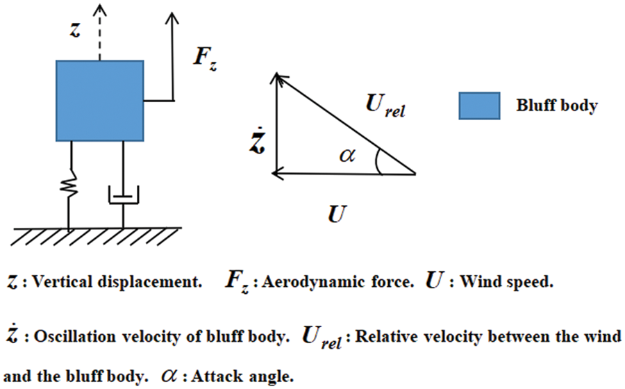
Figure 1: A schematic of the bluff body undergoing galloping
Due to the characteristics of galloping phenomenon, researchers added a pair of piezoelectric layers to the beam, using the piezoelectric effect to convert the vibration energy into electrical energy [40,41]. A schematic of the galloping energy harvester is plotted in Fig. 2, which mainly consists of load resistance, piezoelectric layers, cantilever beam, and bluff body. The bluff body makes an unstable motion in the
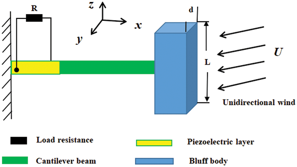
Figure 2: A schematic of the galloping energy harvester
For galloping energy harvesters, the excellent design must consider the impact of the surrounding random factors on the performance in practical applications. Herein, this paper focuses on the response characteristics of the galloping energy harvester under random parameter excitation. According to [42,43], the corresponding mathematical model of the galloping energy harvester under random parameter excitation shown in Fig. 2 can be expressed as:
where
For the model to describe the oscillation characteristics of the galloping energy harvester more accurately, a nonlinear restoring force is employed in this study [29]. The nonlinear restoring force
where
From the application perspective, it is unavoidable that the energy harvester will be influence by the stochastic factors from the system itself. Herein, an ergodic bounded random excitation
where
Next, to facilitate the analysis, scaled transformed
where
3 First-Order Approximate Solutions
In this section, due to the property that the speed of the bluff body motion is much slower than the wind speed in the galloping phenomenon, the multi-scales method is used to analyze the approximate analytical solution. Firstly, assume that the approximate solutions under multiple timescales of Eqs. (5) and (6) can be expressed as follows:
where
Defining the derivative operators represented by the partial derivative operators
Substituting Eqs. (7)–(11) into Eqs. (6) and (7), then the coefficients of the same power of
where
where
It can be observed that Eq. (18) will produce resonance terms when the excitation frequency
After solving A and
4 Stability and Moment Analysis
In this section, the stability of the trivial solutions and nontrivial solutions are discussed, respectively. Evidently,
Let
It is apparent from Eqs. (25) and (26) that
where
where
Next the Lyapunov exponent is employed to study the stability of the trivial solutions. For any initial values
where
The trivial solution of Eqs. (23) and (24) is stable when
Next, the moment method will be used to study the stability of nontrivial solutions. And the It^o stochastic differential equations can be derived as follows:
For the deterministic case of
To explore the impact of random excitation, the perturbation terms
Substituting Eqs. (35) and (36) into Eqs. (31) and (32), the linearized differential equations with respect to the perturbation terms
According to Eqs. (37) and (38), combining the moment method and the property as follows:
the perturbation terms
Therefore, the response moments of the nontrivial solutions of Eqs. (35) and (36) can be obtained from Eqs. (40) and (41) as follows:
Next, from the Eqs. (22), (44) and (45), the corresponding response moments of the voltage amplitude can be obtained as follows:
In this section, the response characteristics of the galloping energy harvester are analyzed based on above theoretical results. The parameters are chosen as
For the case of
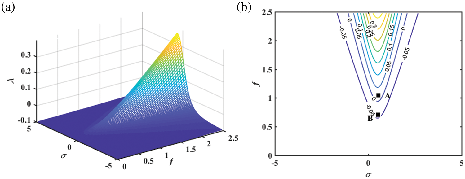
Figure 3: Largest Lyapunov exponents: (a) Mesh surface; (b) Isohypse curves
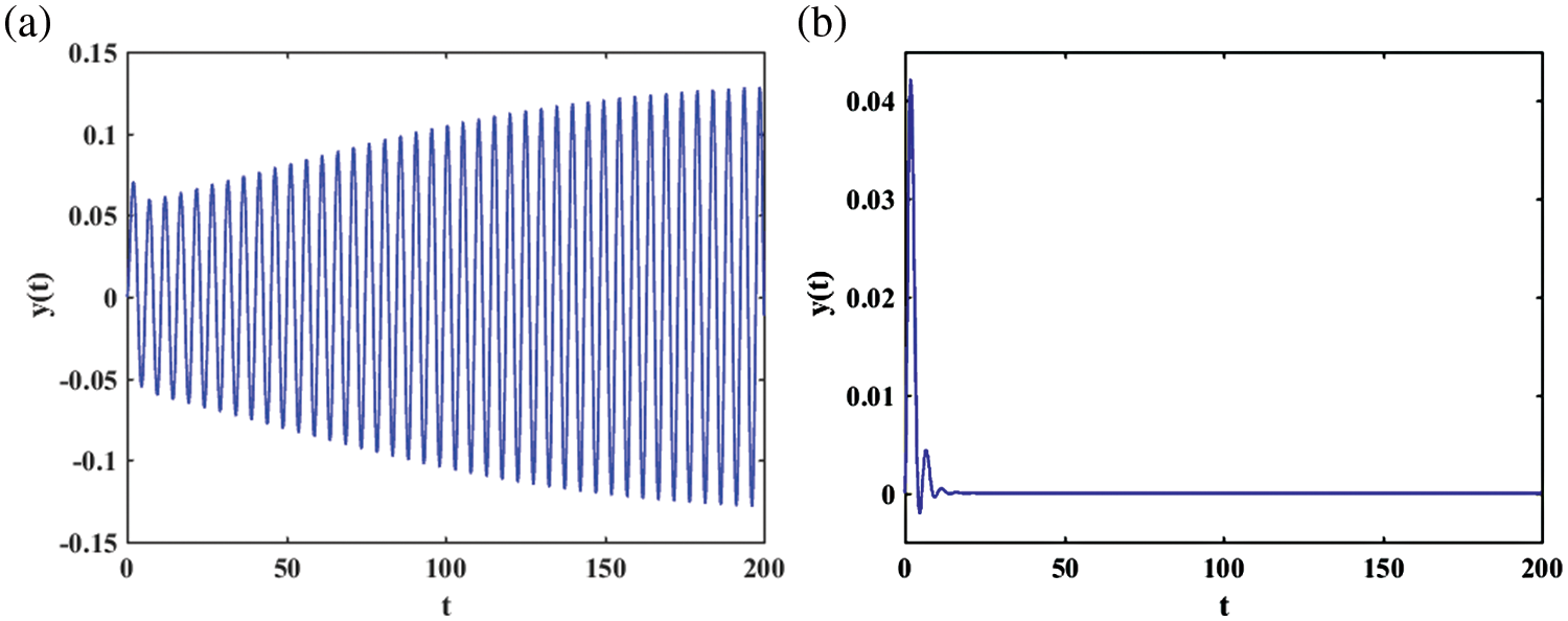
Figure 4: Time-domain response displacement of the galloping energy harvester: (a)
For the case of nontrivial solutions, since the displacement amplitude and voltage amplitude of the steady-state moments are proportional to each other, the response characteristics of the displacement amplitude are similar to those of the voltage amplitude. Herein, only the response characteristics of the voltage amplitude are investigated.
Fig. 5 shows the variations of the response moments
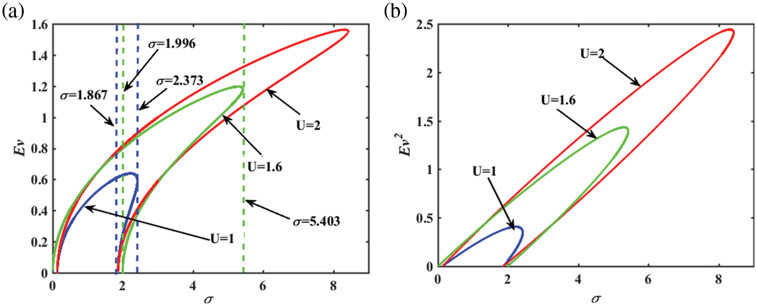
Figure 5: (a) First-order steady-state moment of voltage; (b) Second-order steady-state moment of voltage of the galloping energy harvester with tuning parameters
Fig. 6 shows the impact of the cubic stiffness coefficient
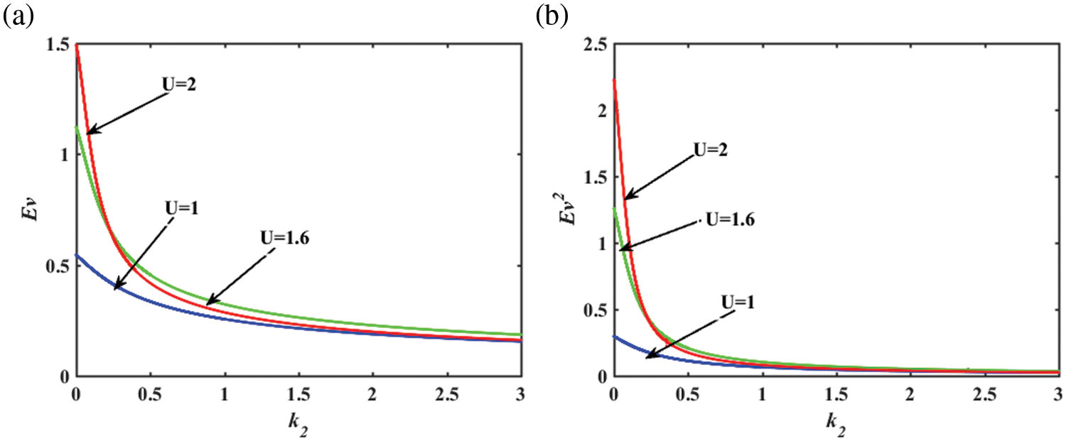
Figure 6: (a) First-order steady-state moment of voltage; (b) Second-order steady-state moment of voltage of the galloping energy harvester with the cubic stiffness coefficient
Fig. 7 shows the curve of the response moments
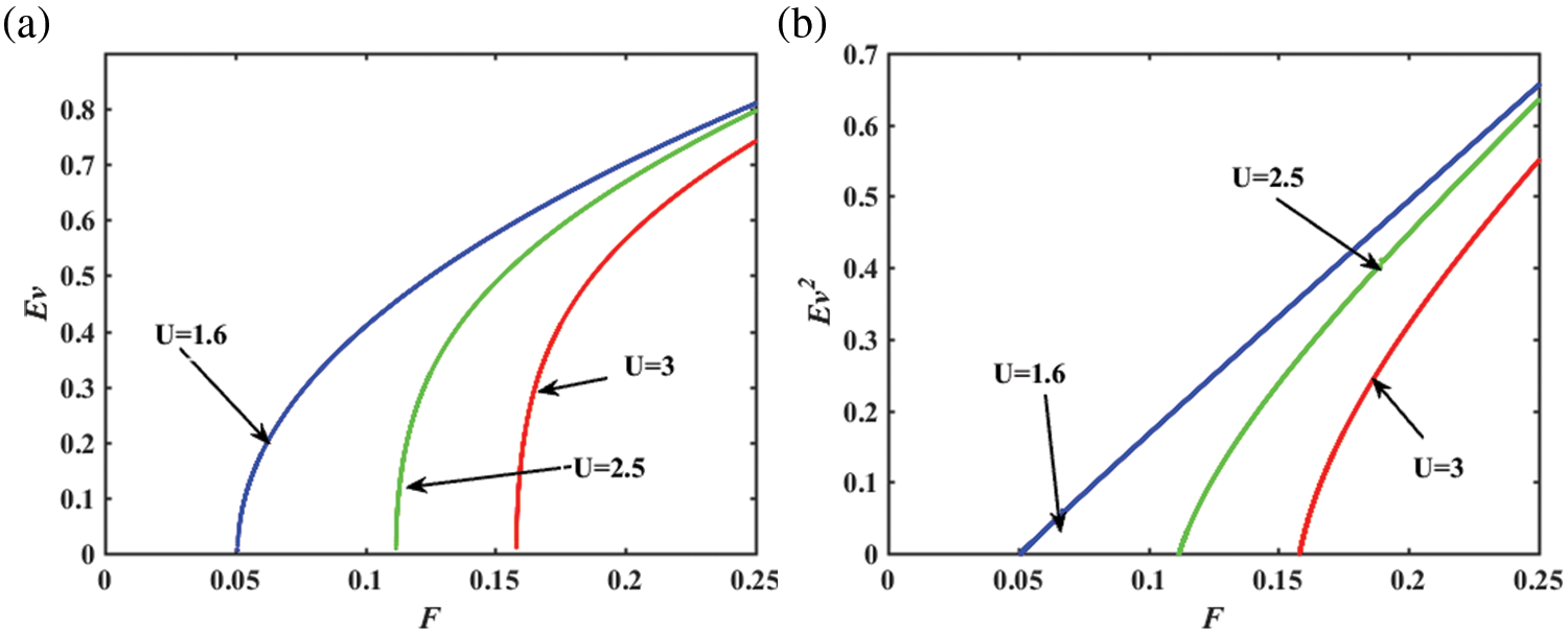
Figure 7: (a) First-order steady-state moment of voltage; (b) Second-order steady-state moment of voltage of the galloping energy harvester with the excitation intensity
Due to the fact that the spectral density of bounded noise is very complex, the analytical expression of PDF cannot be obtained by the currently known methods. Therefore, in order to further explore the impact of wind speed and random noise on the performance of the galloping energy harvester, Monte-Carlo simulation is used to numerically solve the stationary PDF of Eqs. (5) and (6). Fig. 8 shows the PDF of displacement and velocity under different wind speed. It can be seen that the PDF of displacement and velocity have similar curves in Figs. 8a and 8b, and both show two peaks and the “crater” phenomenon, which are caused by the galloping and demonstrates the quasi-periodic oscillatory properties of the galloping energy harvester.
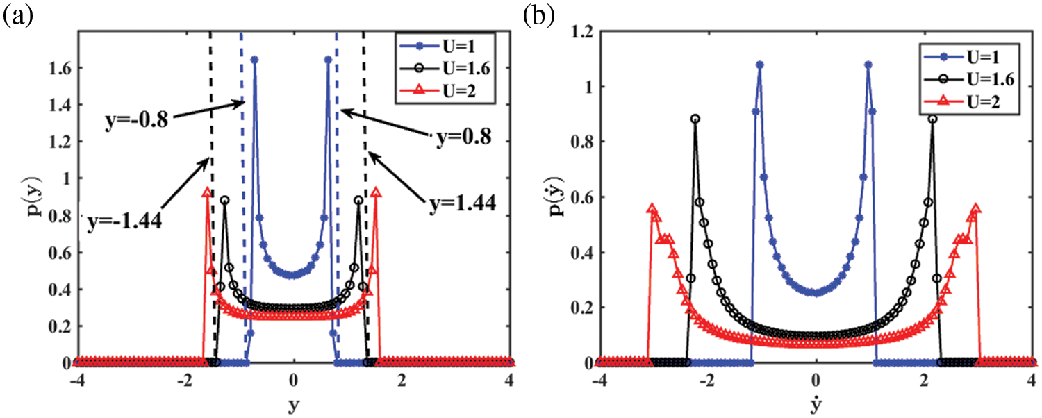
Figure 8: (a) The displacement PDF; (b) The velocity PDF of the galloping energy harvester with
Meanwhile, the higher the wind speed U is, the stronger the periodic galloping vibration due to the enhanced aerodynamic instability, and the more prone the bluff body to vibration. For example, when
Fig. 9 shows the PDF of the displacement and velocity under different damping ratios
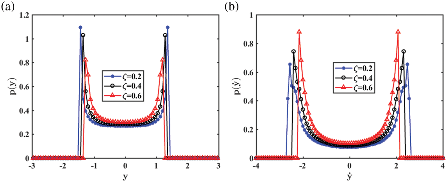
Figure 9: (a) The displacement PDF; (b) The velocity PDF of the galloping energy harvester with
Fig. 10 shows the PDF of the displacement and velocity under electromechanical coupling coefficients
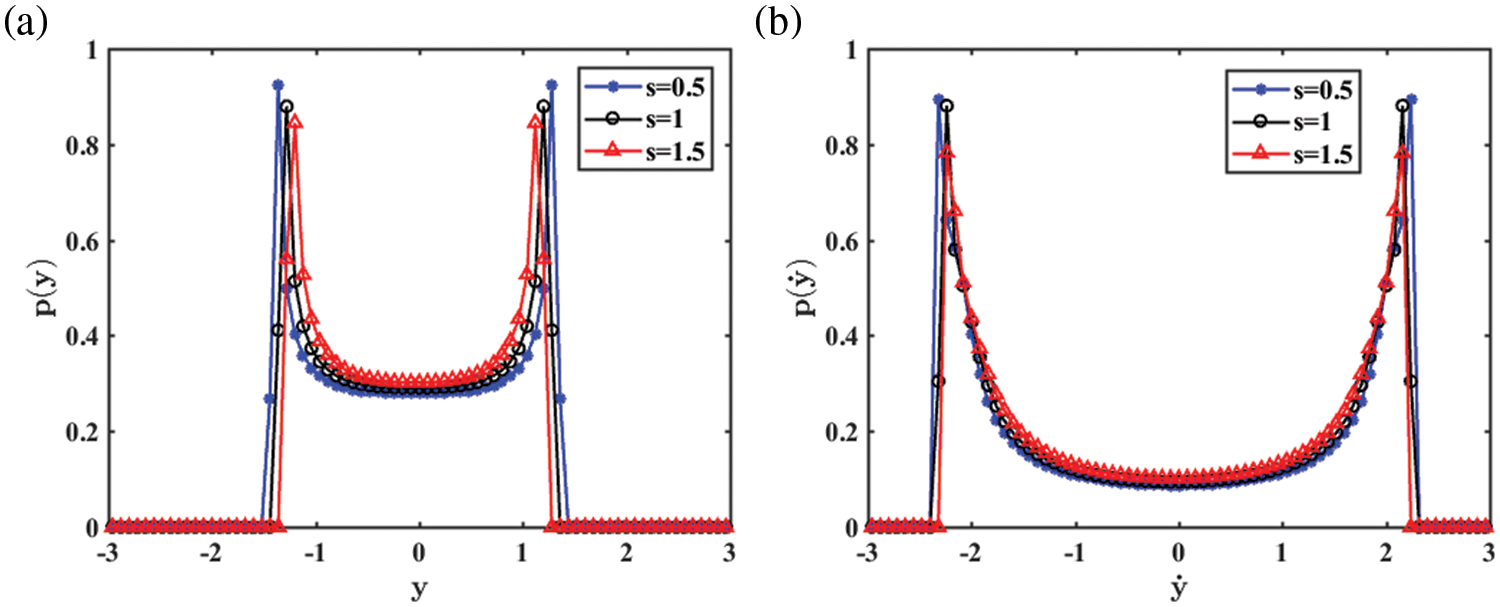
Figure 10: (a) The displacement PDF; (b) the velocity PDF of the galloping energy harvester with
A galloping energy harvester under bounded parameter excitation is investigated theoretically. Due to the properties of the galloping phenomenon, the multi-scales method is employed to study the first-order approximate solution of the galloping energy harvester, and an expression for the solution is derived. Then the stability of the trivial solutions and nontrivial solutions are discussed, respectively. Analytical expressions for the LLE, which determines the stability of the trivial solution, are obtained. The numerical results show that the LLE reaches the maximum at the center of the unstable region, which is around the resonance region, and beyond the region is stability. The analytical expressions for the response moments of the nontrivial solutions are obtained by the moment method. The results show that the tuning parameters, the cubic stiffness coefficient, and the excitation strength, have a significant impact on the dynamic characteristics of the steady-state moments. The tuning parameters will cause the system to generate a multi-solution region. And the voltage output of the energy harvester can be controlled by adjusting the cubic coefficient. In addition, the stationary PDF was obtained by Monte-Carlo simulation. It found that the performance of the galloping energy harvester is correlated with wind speed, the damping ratio, and the PZT materials. The output voltage of the energy harvester can be increased by adjusting the damping rate and selecting suitable PZT materials. And the damping ratios should be reduced as much as possible when designing the galloping energy harvester. In conclusion, the stochastic response properties of the galloping energy harvester under bounded random parameter excitation are revealed. In the future, the relevant results can provide a guide for the optimization and design of energy harvesters.
Funding Statement: This work was supported by the National Natural Science Foundation of China (Grant Nos. 12172266, 12272283), Young Talent Fund of University Association for Science and Technology in Shaanxi, China (Grant No. 20200503), the Bilateral governmental personnel exchange project between China and Slovenia for the years 2021–2023 (Grant No. 12), Joint University Education Project between China and East European (Grant No. 2021122), the Fundamental Research Funds for the Central Universities (Grant No. JB210703).
Conflicts of Interest: The authors declare that they have no conflicts of interest to report regarding the present study.
References
1. Soni, P., Pal, A. K., Islam, S. H. (2019). An improved three-factor authentication scheme for patient monitoring using WSN in remote health-care system. Computer Methods and Programs in Biomedicine, 182, 105054. [Google Scholar] [PubMed]
2. Lanzolla, A., Spadavecchia, M. (2021). Wireless sensor networks for environmental monitoring. Sensors, 21(4), 1172. [Google Scholar] [PubMed]
3. Kim, D. S., Tran-Dang, H. (2019). Wireless sensor networks for industrial applications. In: Industrial sensors and controls in communication networks, Springer, Cham. [Google Scholar]
4. Miao, G., Fang, S., Wang, S., Zhou, S. (2022). A low-frequency rotational electromagnetic energy harvester using a magnetic plucking mechanism. Applied Energy, 305, 117838. [Google Scholar]
5. Yang, T., Cao, Q., Hao, Z. (2021). A novel nonlinear mechanical oscillator and its application in vibration isolation and energy harvesting. Mechanical Systems and Signal Processing, 155, 107636. [Google Scholar]
6. Huang, D., Han, J., Zhou, S., Han, Q., Yang, G. et al. (2022). Stochastic and deterministic responses of an asymmetric quad-stable energy harvester. Mechanical Systems and Signal Processing, 168, 108672. [Google Scholar]
7. Huang, D., Chen, J., Zhou, S., Fang, X., Li, W. (2021). Response regimes of nonlinear energy harvesters with a resistor-inductor resonant circuit by complexification-averaging method. Science China Technological Sciences, 64(6), 1212–1227. [Google Scholar]
8. Zhou, S., Zuo, L. (2018). Nonlinear dynamic analysis of asymmetric tristable energy harvesters for enhanced energy harvesting. Communications in Nonlinear Science and Numerical Simulation, 61, 271–284. [Google Scholar]
9. Yan, B., Zhou, S., Zhao, C., Wang, K., Wu, C. (2019). Electromagnetic energy harvester for vibration control of space rack: Modeling, optimization, and analysis. Journal of Aerospace Engineering, 32(1), 04018126. [Google Scholar]
10. Fang, S., Chen, K., Lai, Z., Zhou, S., Liao, W. H. (2023). Analysis and experiment of auxetic centrifugal softening impact energy harvesting from ultra-low-frequency rotational excitations. Applied Energy, 331, 120355. [Google Scholar]
11. Fang, S., Chen, K., Xing, J., Zhou, S., Liao, W. H. (2021). Tuned bistable nonlinear energy sink for simultaneously improved vibration suppression and energy harvesting. International Journal of Mechanical Sciences, 212, 106838. [Google Scholar]
12. Yang, K., Wang, J., Yurchenko, D. (2019). A double-beam piezo-magneto-elastic wind energy harvester for improving the galloping-based energy harvesting. Applied Physics Letters, 115(19), 193901. [Google Scholar]
13. Hu, G., Wang, J., Qiao, H., Zhao, L., Li, Z. et al. (2021). An experimental study of a two-degree-of-freedom galloping energy harvester. International Journal of Energy Research, 45(2), 3365–3374. [Google Scholar]
14. Bibo, A., Daqaq, M. F. (2014). On the optimal performance and universal design curves of galloping energy harvesters. Applied Physics Letters, 104(2), 023901. [Google Scholar]
15. Huang, D., Han, J., Li, W., Deng, H., Zhou, S. (2023). Responses, optimization and prediction of energy harvesters under galloping and base excitations. Communications in Nonlinear Science and Numerical Simulation, 119, 107086. [Google Scholar]
16. Tang, L., Zhao, L., Yang, Y., Lefeuvre, E. (2014). Equivalent circuit representation and analysis of galloping-based wind energy harvesting. IEEE/ASME Transactions on Mechatronics, 20(2), 834–844. [Google Scholar]
17. Sun, W., Seok, J. (2021). Novel galloping-based piezoelectric energy harvester adaptable to external wind velocity. Mechanical Systems and Signal Processing, 152, 107477. [Google Scholar]
18. Tan, T., Zuo, L., Yan, Z. (2021). Environment coupled piezoelectric galloping wind energy harvesting. Sensors and Actuators A: Physical, 323, 112641. [Google Scholar]
19. Zhou, S., Li, J., Wang, J., Li, G., Wang, Q. (2019). Vortex-induced vibrational tristable energy harvester: Design and experiments. IOP Conference Series: Materials Science and Engineering, 531(1), 012011. [Google Scholar]
20. Alhadidi, A. H., Daqaq, M. F. (2016). A broadband bi-stable flow energy harvester based on the wake-galloping phenomenon. Applied Physics Letters, 109(3), 033904. [Google Scholar]
21. McCarthy, J. M., Watkins, S., Deivasigamani, A., John, S. J. (2016). Fluttering energy harvesters in the wind: A review. Journal of Sound and Vibration, 361, 355–377. [Google Scholar]
22. Yang, K., Qiu, T., Wang, J., Tang, L. (2020). Magnet-induced monostable nonlinearity for improving the VIV-galloping-coupled wind energy harvesting using combined cross-sectioned bluff body. Smart Materials and Structures, 29(7), 07LT01. [Google Scholar]
23. Kitio Kwuimy, C. A., Litak, G., Borowiec, M., Nataraj, C. (2012). Performance of a piezoelectric energy harvester driven by air flow. Applied Physics Letters, 100(2), 024103. [Google Scholar]
24. Daqaq, M. F. (2015). Characterizing the response of galloping energy harvesters using actual wind statistics. Journal of Sound and Vibration, 357, 365–376. [Google Scholar]
25. Xu, M., Wang, B., Li, X., Zhou, S., Yurchenko, D. (2022). Dynamic response mechanism of the galloping energy harvester under fluctuating wind conditions. Mechanical Systems and Signal Processing, 166, 108410. [Google Scholar]
26. Yang, K., Abdelkefi, A., Li, X., Mao, Y., Dai, L. et al. (2021). Stochastic analysis of a galloping-random wind energy harvesting performance on a buoy platform. Energy Conversion and Management, 238, 114174. [Google Scholar]
27. Abdelkefi, A., Yan, Z., Hajj, M. R. (2013). Nonlinear dynamics of galloping-based piezoaeroelastic energy harvesters. The European Physical Journal Special Topics, 222(7), 1483–1501. [Google Scholar]
28. Yang, Y., Zhao, L., Tang, L. (2013). Comparative study of tip cross-sections for efficient galloping energy harvesting. Applied Physics Letters, 102(6), 064105. [Google Scholar]
29. Bibo, A., Alhadidi, A. H., Daqaq, M. F. (2015). Exploiting a nonlinear restoring force to improve the performance of flow energy harvesters. Journal of Applied Physics, 117(4), 045103. [Google Scholar]
30. Na, Y., Lee, M. S., Lee, J. W., Jeong, Y. H. (2020). Wind energy harvesting from a magnetically coupled piezoelectric bimorph cantilever array based on a dynamic magneto-piezo-elastic structure. Applied Energy, 264, 114710. [Google Scholar]
31. Wang, J., Geng, L., Zhou, S., Zhang, Z., Lai, Z. et al. (2020). Design, modeling and experiments of broadband tristable galloping piezoelectric energy harvester. Acta Mechanica Sinica, 36(3), 592–605. [Google Scholar]
32. Zhao, D., Hu, X., Tan, T., Yan, Z., Zhang, W. (2020). Piezoelectric galloping energy harvesting enhanced by topological equivalent aerodynamic design. Energy Conversion and Management, 222, 113260. [Google Scholar]
33. Sun, W., Guo, C., Cheng, G., He, S., Yang, Z. et al. (2022). Performance enhancement of galloping-based piezoelectric energy harvesting by exploiting 1:1 internal resonance of magnetically coupled oscillators. Nonlinear Dynamics, 108(4), 3347–3366. [Google Scholar]
34. Yang, T., Cao, Q. (2019). Dynamics and energy generation of a hybrid energy harvester under colored noise excitations. Mechanical Systems and Signal Processing, 121, 745–766. [Google Scholar]
35. Zhang, Y., Jiao, Z., Duan, X., Xu, Y. (2021). Stochastic dynamics of a piezoelectric energy harvester with fractional damping under Gaussian colored noise excitation. Applied Mathematical Modelling, 97, 268–280. [Google Scholar]
36. Yang, Z., Zhou, S., Zu, J., Inman, D. (2018). High-performance piezoelectric energy harvesters and their applications. Joule, 2(4), 642–697. [Google Scholar]
37. Safaei, M., Sodano, H. A., Anton, S. R. (2019). A review of energy harvesting using piezoelectric materials: State-of-the-art a decade later (2008–2018). Smart Materials and Structures, 28(11), 113001. [Google Scholar]
38. Zhao, L., Yang, Y. (2018). An impact-based broadband aeroelastic energy harvester for concurrent wind and base vibration energy harvesting. Applied Energy, 212, 233–243. [Google Scholar]
39. Sobhanirad, S., Afsharfard, A. (2019). Improving application of galloping-based energy harvesters in realistic condition. Archive of Applied Mechanics, 89(2), 313–328. [Google Scholar]
40. Wang, J., Sun, S., Hu, G., Yang, Y., Tang, L. et al. (2021). Exploring the potential benefits of using metasurface for galloping energy harvesting. Energy Conversion and Management, 243, 114414. [Google Scholar]
41. Hu, G., Wang, J., Tang, L. (2021). A comb-like beam based piezoelectric system for galloping energy harvesting. Mechanical Systems and Signal Processing, 150, 107301. [Google Scholar]
42. Zhao, L., Tang, L., Yang, Y. (2013). Comparison of modeling methods and parametric study for a piezoelectric wind energy harvester. Smart Materials and Structures, 22(12), 125003. [Google Scholar]
43. Ma, X., Zhou, S. (2022). A review of flow-induced vibration energy harvesters. Energy Conversion and Management, 254, 115223. [Google Scholar]
44. Huang, D., Zhou, S., Yang, Z. (2019). Resonance mechanism of nonlinear vibrational multistable energy harvesters under narrow-band stochastic parametric excitations. Complexity, 2019, 1050143. [Google Scholar]
45. Huang, D., Zhou, S., Li, R., Yurchenko, D. (2022). On the analysis of the tristable vibration isolation system with delayed feedback control under parametric excitation. Mechanical Systems and Signal Processing, 164, 108207. [Google Scholar]
Cite This Article
 Copyright © 2023 The Author(s). Published by Tech Science Press.
This work is licensed under a Creative Commons Attribution 4.0 International License , which permits unrestricted use, distribution, and reproduction in any medium, provided the original work is properly cited.
 Downloads
 Citation Tools