
 Submit a Paper
 Propose a Special lssue
 Open Access
ARTICLE
Multi-Material Topology Optimization for Spatial-Varying Porous Structures
1 State Key Laboratory for Alternate Electrical Power System with Renewable Energy Sources, North China Electric Power University, Beijing, 102206, China
2 School of Mechanical and Automotive Engineering, South China University of Technology, Guangzhou, 510640, China
3 Faculty of Materials and Manufacturing, Beijing University of Technology, Beijing, 100124, China
4 Institute of Structural Health Monitoring and Control, School of Mechanics, Civil Engineering & Architecture, Northwestern Polytechnical University, Xi’an, 710072, China
* Corresponding Author: Kai Long. Email:
Computer Modeling in Engineering & Sciences 2024, 138(1), 369-390. https://doi.org/10.32604/cmes.2023.029876
Received 12 March 2023; Accepted 22 May 2023; Issue published 22 September 2023
 View Full Text
 Download PDF
Abstract
This paper aims to propose a topology optimization method on generating porous structures comprising multiple materials. The mathematical optimization formulation is established under the constraints of individual volume fraction of constituent phase or total mass, as well as the local volume fraction of all phases. The original optimization problem with numerous constraints is converted into a box-constrained optimization problem by incorporating all constraints to the augmented Lagrangian function, avoiding the parameter dependence in the conventional aggregation process. Furthermore, the local volume percentage can be precisely satisfied. The effects including the global mass bound, the influence radius and local volume percentage on final designs are exploited through numerical examples. The numerical results also reveal that porous structures keep a balance between the bulk design and periodic design in terms of the resulting compliance. All results, including those for irregular structures and multiple volume fraction constraints, demonstrate that the proposed method can provide an efficient solution for multiple material infill structures.Keywords
Porous structures outperform traditional bulk designs or single-scale structure design in terms of resistance to localized material damage or manufacturing defects, force fluctuation and buckling. On the other hand, structural topology optimization (TO) and additive manufacturing both provide robust design and fabrication tools that significantly boost the likelihood of using porous structures in the engineering applications. Recent years has witnessed the vigorous advancements in the field of spongy structures as a result of AM-based TO technique [1–3].
Recently, it was reported that a breakthrough in the design and manufacture of voxelated soft matter has been accomplished through the use of a multi-material multi-nozzle printing technique [4]. Additionally, the majority of previous study has concentrated on the pattern of single material porous structure. Motivated by these realistic possibilities and demands, this work aims to establish a density-based method, specifically the Solid Isotropic Material with Penalty (SIMP) scheme, for topological design of porous structures via optimal proper material selection. The suggested algorithm for multi-material optimization can be implemented to solve the compliance minimization problem subject to a single mass or several individual volumes constraints on each phase. To manage the porosity on the constituent materials, massive local percentage constraints are imposed on each voxel. The main contribution of the present work is focus on an alternative approach for generating porous structure, by constructing a sequence of box-constrained optimization problems in the form of an Augmented Lagrangian function. The suggested AL-based formulation is capable of handling the global and extensive local constraints, resulting in designs that do not exceed the upper limits anywhere in structural design domain.
The present article proceeds as follows. After reviewing existing literature in Section 2, this paper formulates the TO problems for multi-material porous structure in Section 3. Section 4 presents several numerical examples and discussions. The concluding remarks are drawn in Section 5.
This section summarizes prior research that is relevant to this topic, including TO approaches for porous and multi-material structures design. On the basis of these publications, the subsequent section will introduce the proposed formulation for multi-phase porous structures and the augmented Lagrangian function.
2.1 Topology Optimization on Porous Structures
In the existing studies, spongy structures have been extensively investigated by utilizing the concept of multi-scale design via numerical homogenization or substructure approach [5], in which both macrostructure and microstructure evolve concurrently to achieve the excellent system performance. This two-scale method considerably expands the design space, theoretically increasing the probability of a superior solution. Rodrigues et al. [6] initially presented a hierarchical model for macrostructure consisting element-wise cellular materials while Zhang et al. [7] suggested the layer-wise porous media at macro scale. This topic sparked widespread attention in part originated from the advancements in both computing power and additive manufacturing [8–10]. One popular tactic is to establish a certain periodic or a range of representative porous or composite units at microscopic scale for the fixed or synchronously varying macrostructure. Considering the convenience of manufacturing, the connectivity issue must be addressed efficiently. Radman et al. [11] presented a way to guarantee the connectivity of the adjacent cellular microstructures by global filtering. Yang et al. [12] developed a shape metamorphosis technology to impose the connectivity conditions on graded microstructures. Wu et al. [13] synthesized substructure and surrogate model to approximate the reduced substructure with penalization (ARSP) formulation. The ARSP model directly addresses the connectivity issues and ignorance of the size effects inherent in traditional homogenization. Luo et al. [14] suggested a self-connected material interpolation for structures containing various lattice structures. Li et al. [15] proposed an erode-dilate approach for generating a succession of quasi-periodic microstructures, with the goal of avoiding the disconnection in a natural way.
The de-homogenization approach is alternative approach for producing the well-connected microstructures in a spatial-varying structure [16]. In recent years, much attention has been devoted in this research field for its conceptual simplicity and computational efficiency [17–19]. Nowadays the de-homogenization method has been successfully expanded to 2D and 3D structures. We direct interested readers to the comprehensive reviews for details on various multi-scale approaches [1–4].
In contrast to the multi-scale optimization, the full-scale technique disregards the separation between macro- and micro-structures and imposes periodic repetitions or local porosity control on the mono-scale structure. Owe to the lack of awareness of the separation between micro and macro scales, the connectivity troubles can be straightforwardly avoided in such a mono-scale strategy, albeit at the cost of massive computational consumptions. The bone-like structure is obtained automatically by the maximum length restriction, which can be traced back to Guest [20] and others [21–25]. Experiments have confirmed the infill structure’s superior resistance to buckling [26]. Wu et al. [27] put an upper limit on the localized volume around each voxel in the given region. The p-norm function aggregates numerous local constraints, allowing for efficient solutions. An amount of studies following the local volume constraints have been furthered including the shell-infill structures, multi-phase infill structures, functionally graded porous structures and self-supporting infill structures [28–32]. Dou [33] imposed implicit control over local volume proportion via morphology transformation mode, which was extended to the thermo-mechanical buckling problem [34]. Long et al. [35,36] recently suggested a cluster-free formulation for the local volume constraints to verify that the upper bounds can be satisfied precisely. Hu et al. [37] introduced the block-wise similarity constraints into the generative design by mimicking textures. Similar to the work by Schmidt et al. [38], Zhao et al. [39] proposed two local constraints for achieving multiple levels of porosity. The studies on the topological design on the cellular structures are also extended to level set [40–42] and explicit boundary representation method [43–46], respectively. More recently, Wang et al. [47] suggested an automatic initialization scheme that specifies the topological skeleton of the stress field into the density field, aiming at obtaining a distinct binary design. Park et al. [48] restored the complex internal structure of bone using a TO technique using perimeter control. To achieve connected architect materials, Du et al. [49] included the connectivity index as a constraint in multiscale TO.
2.2 Topology Optimization on Multi-Phase Structures
Thomsen made the earliest attempt on TO of multi-material structures [50]. Sanders et al. [51] proposed a multi-material compliance minimization TO formulation. The optimal designs of unconventional thermal expansion, piezoelectricity and extreme bulk modulus were casted as the three-phase TO problems [52–54]. To reduce the number of design variables, a peak function was chosen as the substitute of the multi-material SIMP [55]. Stegmann et al. [56] formulated the discrete material optimization (DMO) problem for composite laminate shell structure based on numerical gradient. Gao et al. [57] extended DMO method by incorporating a total mass usage, in which the constituent materials are automatically allocated according to the stiffness and stiffness-to-mass ratio. Tavakoli et al. [58] presented a multi-phase TO method based on optimal criteria by establishing a chain of binary phase sub-problems. This novel idea was then furthered into the load variation problem and structure obtained from additive manufacturing, cracked structure and functionally graded structures [59–62]. Bohrer et al. [63] suggested a mixture of isotropic and anisotropic materials to improve the numerical efficiency of the element duplication method. Park et al. [64] presented a three-dimensional multi-resolution implementation of the multi-material TO problem. Bruyneel [65] introduced shape function parameterization (SFP) interpolation into the TO of composite structures with four different fibers types. Gao et al. [66] defined the bi-value coding parameterization scheme as the general form of the SFP method to manage materials with an arbitrary number of constituents. Zuo et al. [67] proposed an ordered multi-material SIMP approach without the use of additional variables, using a segmenting curve to represent each material available within a certain scope. Nowadays, the ordered SIMP approach has also been furthered into the stress-constrained problem [68]. Long and his coworkers [69] presented an alternative choice for handling multi-phase TO problems using exact Hessian information. Liao [70] proposed the NURBS method to represent the density field with the reduced design variables through discrete cosine transform. As a growing focus in the TO community, the other multi-material TO solutions were also given in the phase method [71], bi-direction evolutionary structural method [72], level set method [73,74], moving morphable components method [75,76] and floating projection method [77].
3 Topology Optimization Problem
3.1 Problem Formulation for Multi-Material Porous Structure
The design domain in this paper is composed of biphasic or multi-material infill structures, as indicated in Fig. 1. Two distinct materials coexist in the design domain, cooperatively forming the porous structure. Each phase aims to maximum the system performance by occupying the effective zone. The mechanical properties of the candidate materials are listed in the descending order as Young’s modulus Ej and mass density ρj. For two solid and one void material, the eth elemental Young’s modulus and physical density can be formulated as follows:
where p is the penalization power with typical value 3 for superior convergence in density-based TO.
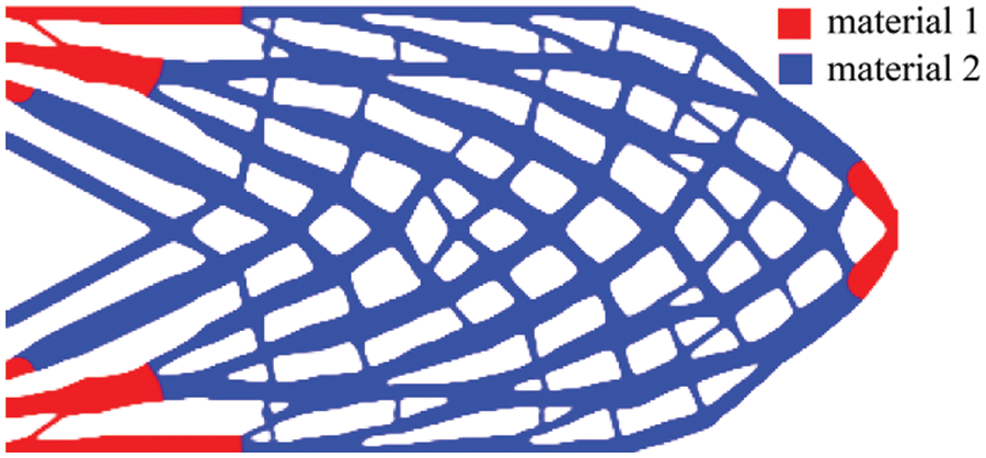
Figure 1: Graphical representation of design problem: Multi-material infill composite structure
Similarly, the Eqs. (1) and (2) can be extended into j-phase materials in the recursive scheme [57]. Generally, the j-phase materials require (j-1) design variables for each element, i.e.,
where J represents the total number of the available material phases.
As can be seen from Eqs. (2) and (3), the design variable
where Se is the set of surrounding elements in a circular region with its influence radius R.
The TO problem with a sole mass constraint can be mathematically stated as follows:
where c is the static compliance; mf and
Similarly, the multi-material TO problem subject to multiple volume fractions imposed on individual phase can thus be formulated as
The only variations between the Eqs. (5) and (6) are constrains on volume fractions of the constituent phases. Here Vj and
By applying the filter to the design variable field, the checkerboard patterns prevalent in the TO community can be effectively suppressed. The solution of the partial differential equation can provide the filtered density field as follows [78]:
where r is the filter radius whose value is usually less than R.
When the filtering techniques are employed, the resulting layouts inevitably contain intermediate densities, most notably on structural boundary. To cope with these unappealing phenomena, the projection maps the filter densities are mapped in such a way [78]:
where β controls the steepness of the projection and a continuation strategy is employed in this study. The optimization procedure starts with a value of 1 and doubles its value per one hundred iterations, until it approaches the maximum of 32.
According to the chain, the sensitivity of the function with respect to
where ue is the eth elemental displacement vector. ke represents the elemental stiffness matrix that is proportional to the Young’s modulus Ee. The formula
where k0 is the elemental stiffness matrix corresponding to Young’s modulus of 1.
The symbol
Take the two-phase material case as example, we can obtain the following the expression:
Here
In the existing study, numerous local volume fraction constraints are generally addressed by the aggregated or clustering techniques. However, the final designs strongly depend on the number of constraint functions and the way defined by the aggregated function. An alternative and attractive approach to efficiently deal with vast local constrains is the AL method [79–82]. This approach is capable of converting a common optimization issue into a box-constrained optimization problem. For instance, the Eq. (6) is converted into a series of sub-problems, by minimizing the defined AL function:
where the superscript k represents the kth optimization loop. The second term and third term are the penalty term according to the global mass constraint and to the local volume constraint in Eq. (6). We normalize the penalty term using the number Nmass and Nvol. Here Nmass is a constant and Nvol is directly proportional to the total number of the element. And Nmass and Nvol are determined by numerical experience. For two parameters, the larger value can relax the constraint function and make the topology configuration clear quickly, while the smaller value will lead to a stricter constraint effect.
The vector
where the symbol
In Eq. (20), both the renewal of the Lagrangian multiplier estimators and the penalty factor at each AL step are as follows:
The box-constrained optimization problem (16) can be solved by a number of efficient algorithms including the method of moving asymptotes (MMA) and steepest descent method with move limits (SDM). In this work, the MMA algorithm is employed to solve the Eq. (16) for its popularity in the topology optimization community. We typically use five MMA iterations per AL iteration in the implementation. The reader can be referred to the literature [81–83] for details.
This section will examine the practicality of the proposed multi-material TO method for porous structures through several 2D numerical tests. Without jeopardizing generality, the geometric size of the design domain, the material prosperities, the external force and resultant compliance are all non-dimensional. The design domain is discretized into bilinear elements with four nodes in plane stress state. The first four examples impose a single mass constraint, whereas the final example specifies multiple volume fractions. The constituent phases share the identical Poisson’s ratio 0.3 but remarkably different Young’s modulus, E1 = 1.2, E2 = 0.8 and E3 = 0.4. All mass densities are normalized as ρ1 = 1.0, ρ2 = 0.6 and ρ3 = 0.2 to facilitate the discussion. The material phases 1, 2 and 3 are displayed in red, blue and green respectively for clarity. The move limit m is set conservatively as 0.01 for the AL function to stabilize the optimization loop. All numerical examples are run on the platform Matlab TM and a PC with an Intel i7 4.20 GHz and 32.0 GB RAM.
The first example demonstrates the disparities between the proposed method and existing method presented by Wu et al. [27] in terms of optimized results. All parameters are the same except the optimization solver. In this case, material phases 1 and 2 are optional. Fig. 2 depicts the design domain, boundary and loading conditions. The planar structure is divided into 640 × 160 uniform mesh with the elemental length 0.5. Both left and right edges are fully fixed while a concentrate load F = −2 is vertically applied at the midpoint on top edge. The global mass percentage and local volume fraction are set as mf = 0.3 and α = 0.6, respectively. The filtering radius of r = 2 and the influence radius of R = 4 are prescribed. Fig. 3 presents the optimized topologies procured from two different approaches. To facilitate understanding, Fig. 4 illustrates the statistical histogram of the local proportion field
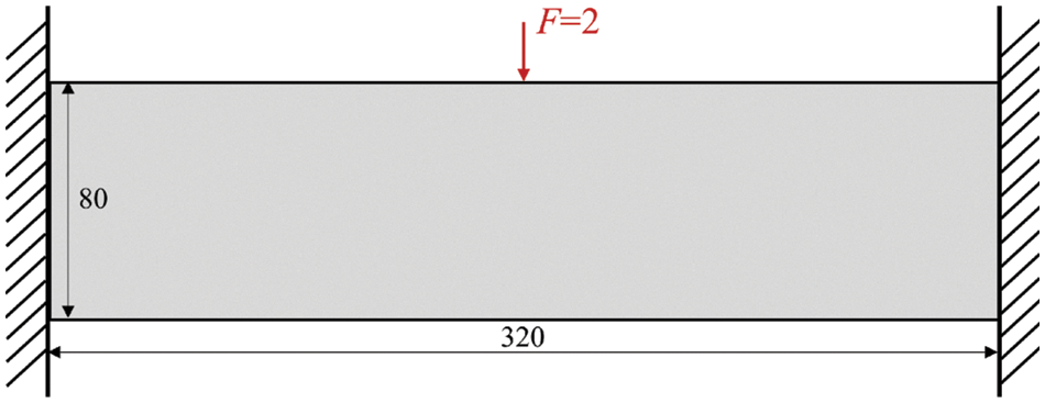
Figure 2: The design domain, boundary and loading conditions
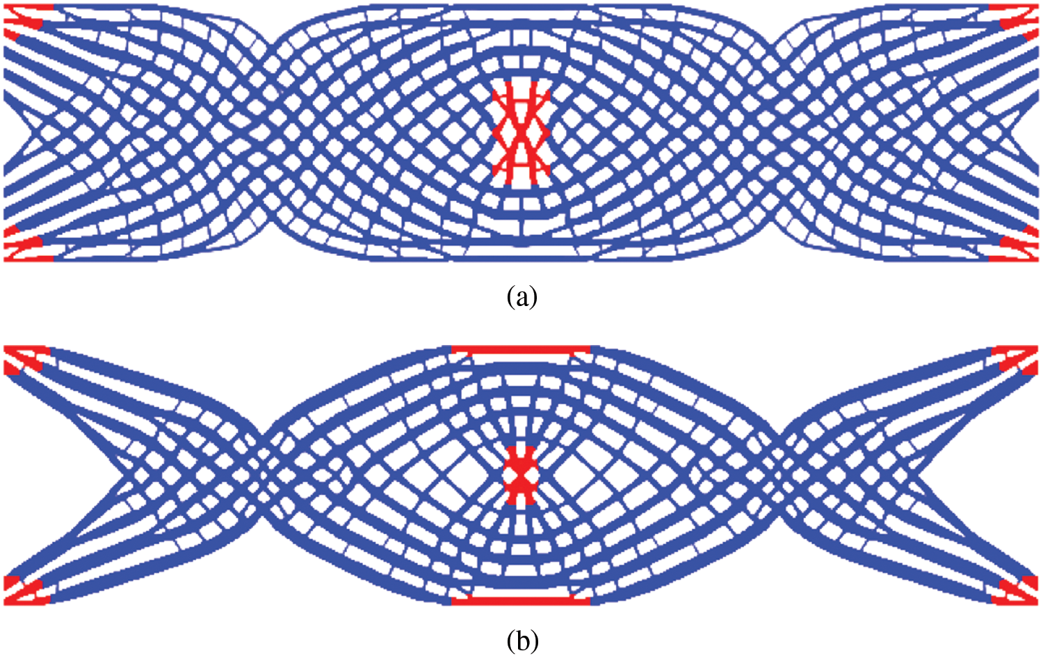
Figure 3: The final layouts from (a) the proposed method: c = 92.118; (b) the existing method: c = 94.568
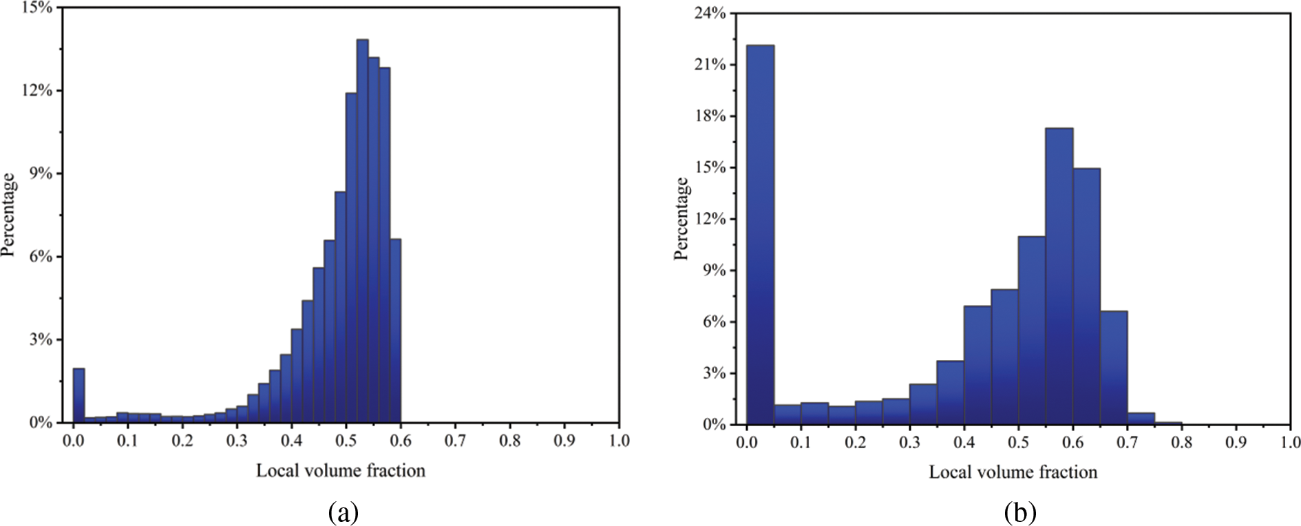
Figure 4: The statistical histogram of local volume fraction
As revealed in Fig. 3, visual discrepancies exist between the optimized topologies for the same specified conditions. The optimized structure from the proposed method is dominated by the spongy substructure. The dissimilarities can primarily attribute to the treatment of the local volume constraints. In Fig. 4a, the maximum value of the local volume percentage is restricted in a narrow range, whereas data of the statistical histogram generated by the existing method scatter around the maximum limit value 0.6 as a sharp contrast shown in Fig. 4b. In literature [80], the optimizer for minimum AL function is expressed explicitly without inner loops. The proposed method requires 608 s, which is significantly less time than 2891 s consumed in the existing method.
When the proposed method is applied, the iterative histories of the resultant compliance c and parameter β are exhibited in Fig. 5, together with structural topologies at the 150th, 250th, 350th, 450th and 550th iteration inserted. The preliminary analysis of the data in Fig. 5 yielded the following findings. The curve representing the objective function steepens dramatically in the early stages, indicating a rise in structural stiffness. As the optimization iterates, the static compliance cure appears to undergo a slight abrupt change when β is doubled. At the 250th iteration step (β = 4), a distinct topological configuration with few blur boundaries emerges. As β increases, the design variables are pushed towards 0 and 1, while compliance converges to an almost constant. Compared with the literature [47], the final design with distinct boundaries is possible in the absence of prior knowledge on the stress distribution.
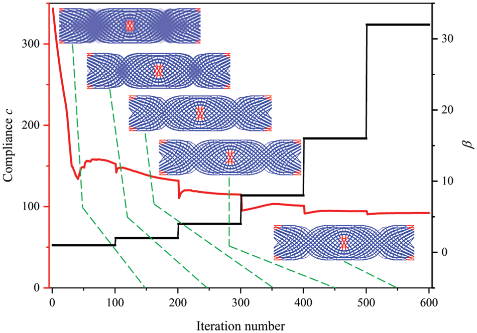
Figure 5: Iterative histories of compliance and the corresponding optimized topologies
To investigate the effect of the elastic modulus on the final designs, the values of E1 is assumed to ranges from 1.4 to 2.0 while the optimized topologies are plotted in Fig. 6.
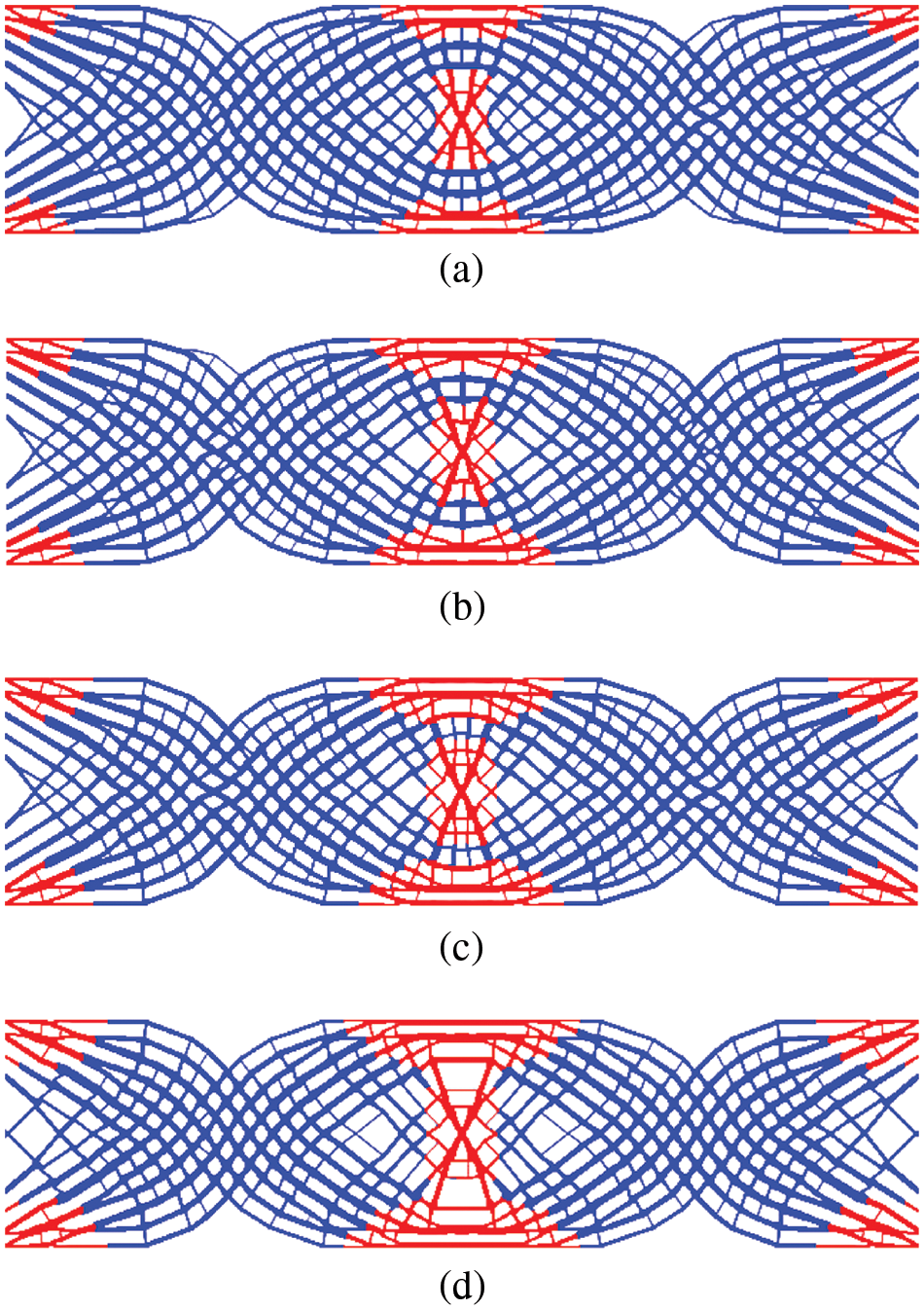
Figure 6: Optimized topologies by varying the Young’s modulus: (a) E1 = 1.4, c = 84.091; (b) E1 = 1.6, c = 81.134; (c) E1 = 1.8, c = 78.647; (d) E1 = 2.0, c = 75.514
As expected, the proportion of the phase 1 increases as the Young’s modulus E1 increases, which the reduction in corresponding compliance. In reality, the multi-material TO selects the stiff material and stiffness-to-density material. The layout of the constituent material differs from the traditional TO due to the local volume fraction.
This example considers the design of the Messerschmitt-Bolkow-Blohm (MBB) structure, utilizing the proposed multi-material TO approach to build an infill structure with a single mass constraint, i.e., mf = 0.3. As sketched in Fig. 7, the two-side supported structure is loaded at its top center by F = −3. The right half is symmetric and discretized by 600 × 200 square elements with elemental length 1. Here a local volume limit of α = 0.6 is employed. The filter radius r and influence radius R are set as 8 and 16, respectively. The design domain is composed of the material phase 1 and 2. Fig. 8 illustrates the final layouts generated by the proposed method employing multiple materials and single phase.
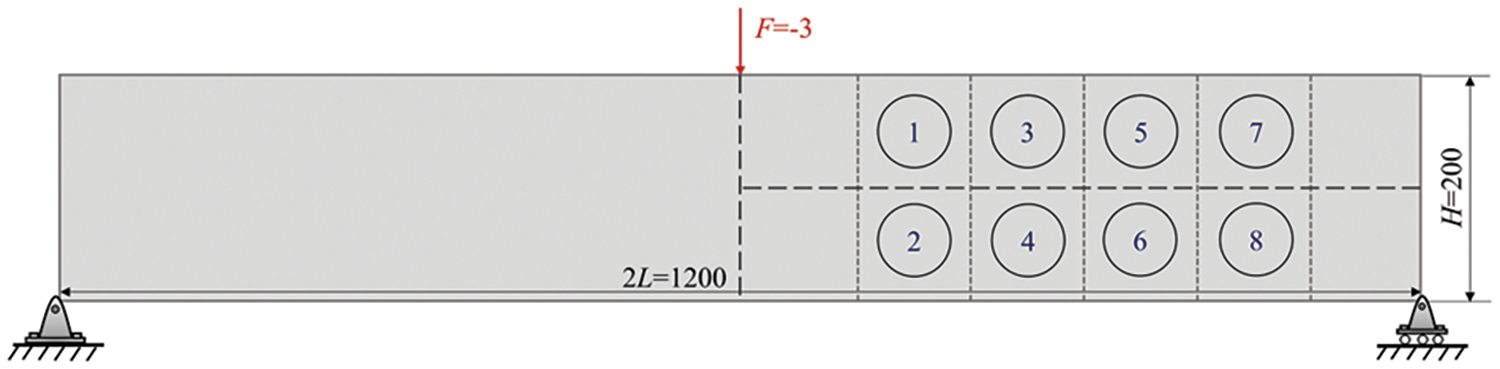
Figure 7: MBB structure design domain
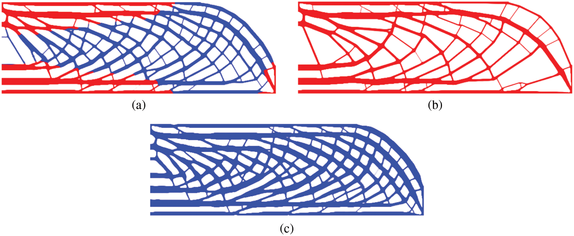
Figure 8: The final layouts obtained from the proposed method using (a) multi-material: c = 615.429; (b) phase 1: c = 649.319; (c) phase 2: c = 744.716
As sketched in Fig. 8, two available materials coexist within the porous structure, each occupying a favorable region. As a result, the compliance 615.429 is slightly below to its counterparts, which have the structure consisting of entirely material 1 or 2. What stands out is that, given the same mass constraint, the system performance can be significantly improved by expanding the material selection. Meanwhile, the optimization algorithm can automatically assign the unique usage of each phase, resulting in a more legitimate and effective material distribution.
Pattern repetition is another frequently used restriction to mimic the porous structure. The MBB design domain is assumed to be divided into 6 × 2 repetitive cells. For comparison, the final layouts constrained by pattern repetition and bulk design are displayed in Figs. 9 and 10.
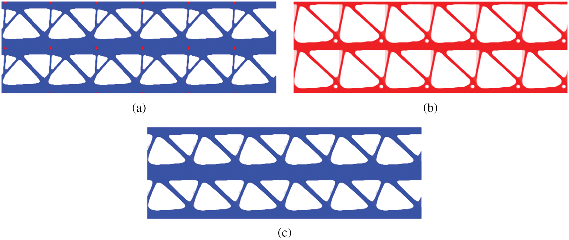
Figure 9: The final layouts restricted by pattern repetition using (a) multi-material: c = 892.74; (b) phase 1: c = 1255.777; (c) phase 2: c = 915.940
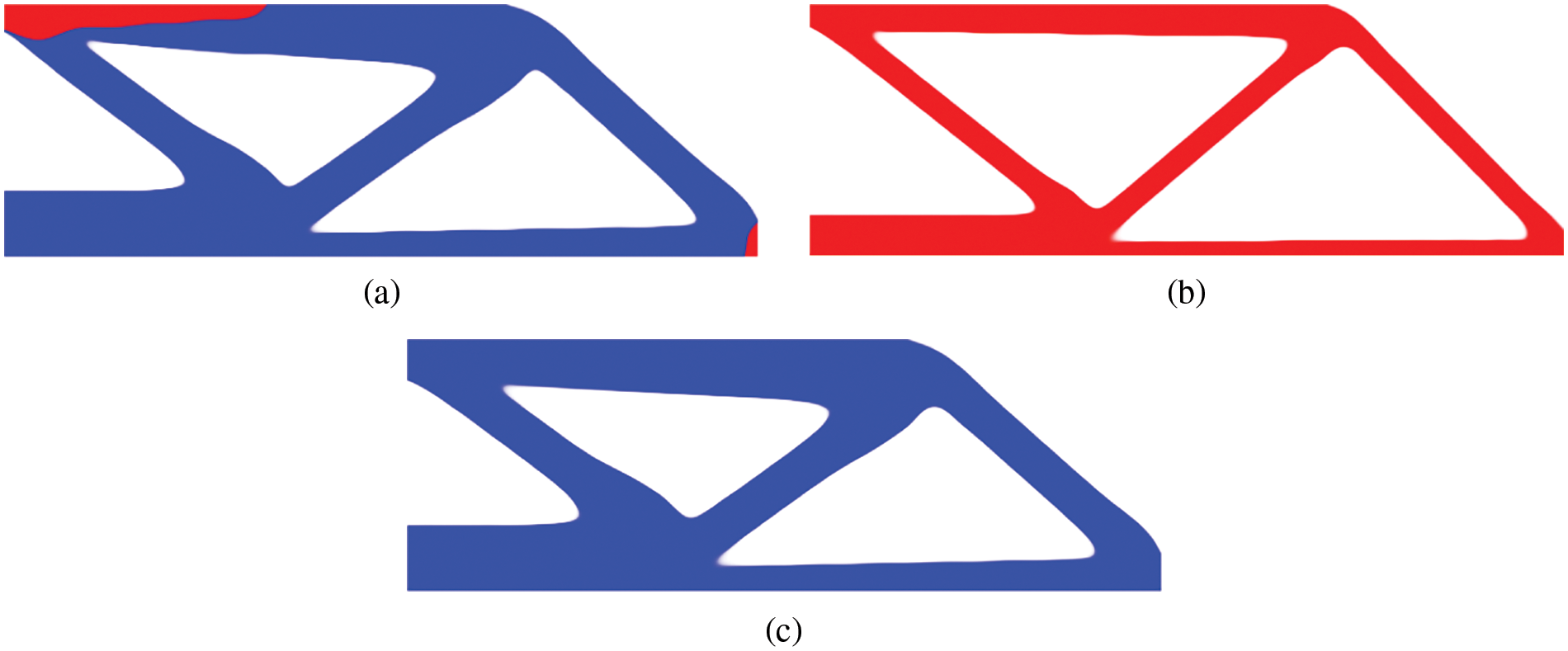
Figure 10: The final layouts obtained from bulk design using (a) multi-material: c = 518.910; (b) phase 1: c = 550.225; (c) phase 2: c = 544.074
As a result of the porous structure analysis, a porous structure containing multiple materials outperforms a porous structure containing sole material in the final designs of the optimized topologies in the periodic design and bulk design. This consequence can be the unswerving auxiliary evidence to manifest the superiority of the composite structure. Additionally, by examining the resulting compliance shown in Figs. 7–9, the periodic design and bulk design exhibits the highest and lowest stiffness respectively. It can be deduced that the repetitive patterns impose a fairly strong constraint on design domain.
Additionally, it is a popularly held opinion that porous structures are more resilient to material deficiency [27]. For a more thorough comparison, we compare structural integrity to the locally regional failure. Eight possible failure zones with a square dimension of 100 × 100 are spread seamlessly over the domain, as shown in Fig. 7. Fig. 11 depicts the total damaged models from the present multi-material TO method to generate bone-like structure. Fig. 10 illustrates the fail-safe region and the resulting variations for the porous structure. The eight regions were respectively arranged by diverse methods according to the numerical value which augment according to the color of the color bar from bottom to the top.
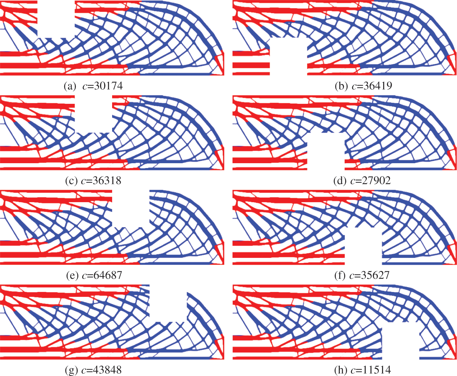
Figure 11: Eight total damaged models with the resultant compliance
In Fig. 11, the void region represents the region which is assumed to be collapse. From an obviously visual standpoint, various damage locations on the structure do not produce a significant impact change. This example demonstrates the benefit of the porous structure when a specific region is destructed. Simultaneously, we performed fail-safe region research on periodic and bulk materials, resulting in three compliance trend curves excavated in different regions as illustrated in Fig. 12.
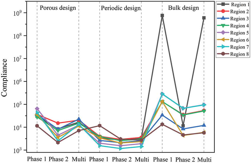
Figure 12: The variations with respect to damage region for three kinds of designs
As illustrated in Fig. 12, the curve of periodic design is reversely gentle. This means that the periodic designs possess the least stable fluctuations as measured by compliance, making them the most conservative designs among all solutions. For bulk designs, several resultant compliance exceed the normal range. It implies that the structure will collapse as a result of such a failure, which cannot be acceptable from the engineering point of view. In general, by accounting for normal conditions and possible material deficiency, the porous structures can maintain a balance between the bulk design and pattern repetitions.
The global mass bound, the influence radius and local volume percentage contributes to determine the porosity. The effects of these criteria on final designs will be discussed as a continuation of the preceding example. To begin, the filter radius r is set to 6 and influence radius R is set to 12. The mass fraction varies between 0.15 and 0.35. The remainders of the parameters are identical to those in examples 2. Fig. 13 illustrates the final designs obtained by altering the mass fraction parameters.
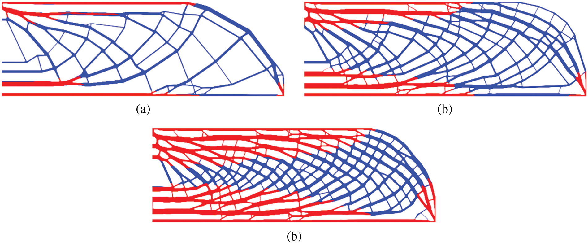
Figure 13: The final designs by varying the mass fraction: (a) mf = 0.15, c = 1071; (b) mf = 0.25, c = 714; (c) mf = 0.35, c = 594
As can be seen, the mass fraction controls both the porosity and space between the base phases. The system stiffness will be efficiently raised as more materials become available, which matches the engineering intuition.
Secondly, the mass fraction mf = 0.35 are specified for two radii of r = 5 and R = 12. The local volume fraction is in the range of 0.6 and 0.8. The final designs by changing the local volume fraction are plotted in Fig. 14. Thirdly, the mass fraction and local volume fraction are given as mf = 0.30 and α = 0.65, respectively. The filter radius and influence radius are divided into four groups: (a) r = 5, R = 10; (b) r = 5, R = 20; (c) r = 10, R = 20; (d) r = 15, R = 20. The final designs for various combinations of two radiuses are depicted in Fig. 15.
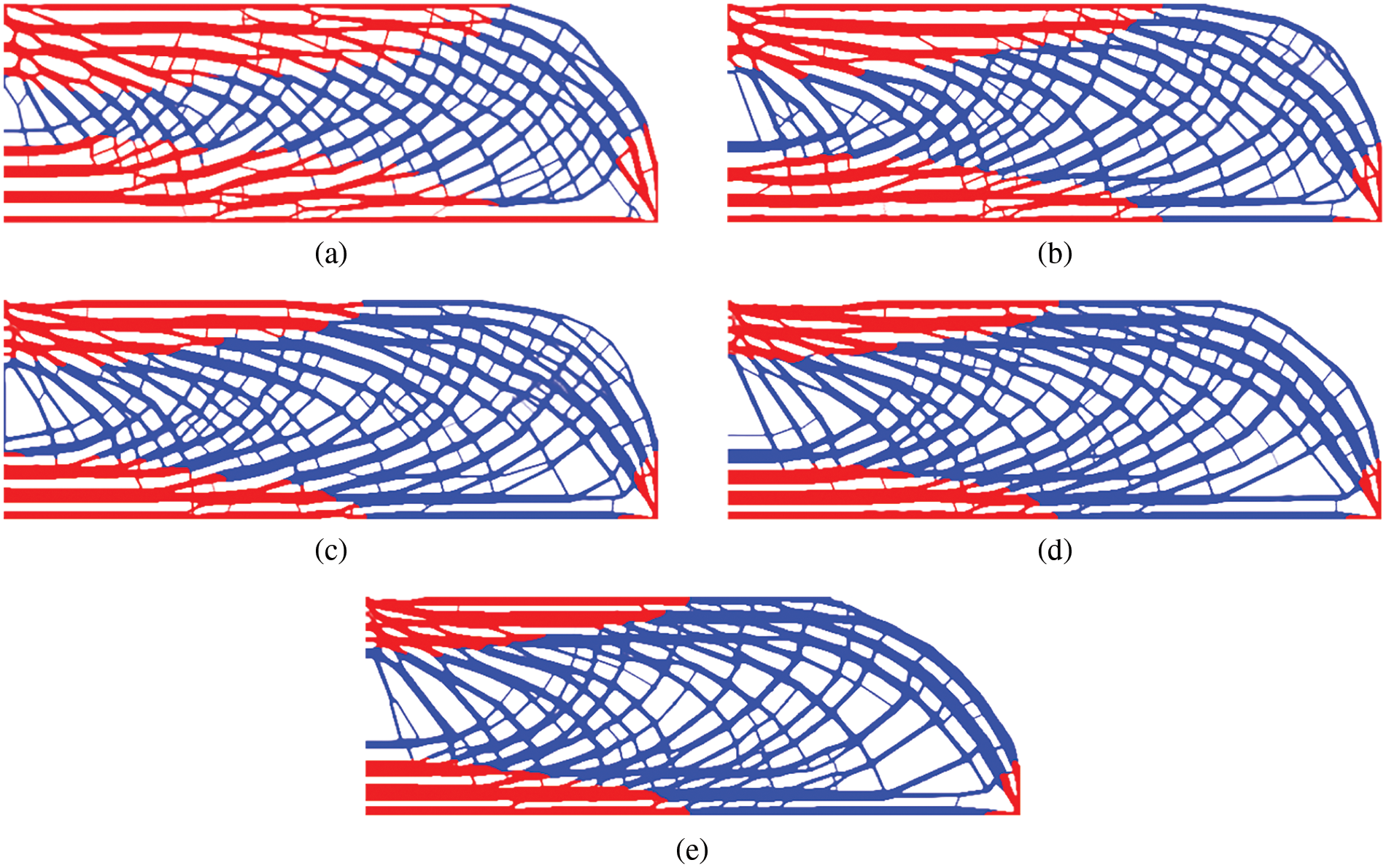
Figure 14: The final designs by varying the local volume fraction: (a) α = 0.60, c = 586.986; (b) α = 0.65, c = 543.282; (c) α = 0.70, c = 521.484; (d) α = 0.75, c = 499.114; (e) α = 0.80, c = 480.439
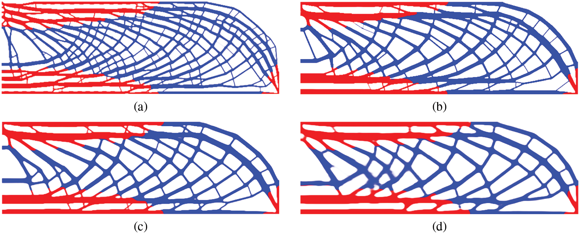
Figure 15: The final designs for various combinations of two radiuses: (a) r = 5, R = 10, c = 627.904; (b) r = 5, R = 20, c = 563.754; (c) r = 10, R = 20, c = 580.656; (d) r = 15, R = 20, c = 611.699
Observed from Figs. 14 and 15, the form of the porous structures is influenced by the parameters α, r and R. Clearly, constituent materials will accumulate in confined spaces, as the local volume fraction increases, reducing system compliance. The bone-like structure in the limit state degrades similarly to conventional bulk designs. The minimum scale size of the structure can be inferred from the filter radius r. The parameter R exerts a prominent impact on the size of the hole from a visual perspective. As the scope of influence is enlarged, the constraint on local volume fraction tends to loosen, evolving towards the conventional TO. Validity is confirmed by the observed occurrences, which are similar to those described in the published literature [27].
To test the feasibility of the current approach in coping with irregular shape and mesh, a 2D bone-like structure is selected for optimization. The finite element model contains 35516 four-node elements and 35913 nodes. The passive region consists of four layers of elements. The bottom edge is completely constrained, whereas left corner on the top side are exerted uniformly distributed load F = 100 and the right with F =
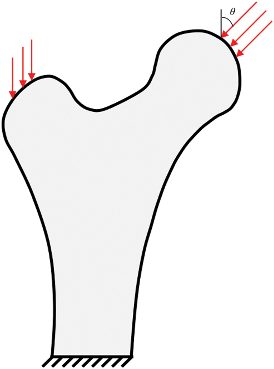
Figure 16: The design domain, boundary and loading condition of a bone-like structure
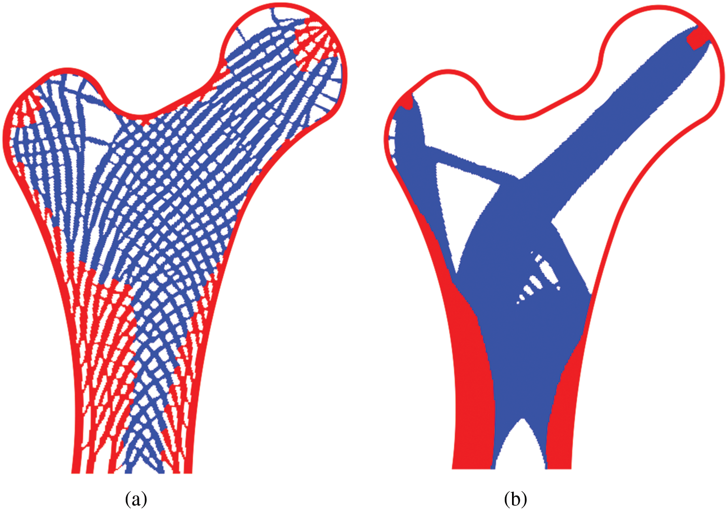
Figure 17: The final designs obtained through (a) porosity control, c = 22610.371; (b) traditional topology optimization, c = 15252.931
Two optimized topologies, as illustrated in Fig. 17, have notable visual distinctions. The strong material occupies a higher proportion in the porous design, whereas the weak phase material fills the central area in the traditional design. To further elaborate the advantage of the porous structure, Fig. 18 depicts compliance variation from two unique topologies at various angles θ. Clearly, the bone-like structure is insensitive to changes in load direction.

Figure 18: Compliance curves with respect to load direction angle θ of two resulting topologies
This example can be viewed as a natural extension of Example 2, in which three materials are available by imposing individual volume fractions. The filter radius r and influence radius R are set as 6 and 12. The local volume fraction for various phases is set as 0.65. The volume fraction for phases 1, 2 and 3 is 0.5, 0.3 and 0.1, respectively. Fig. 19 depicts the optimized topology based on three optional materials.
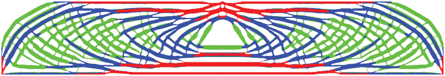
Figure 19: The optimized topology by selecting three candidate material: c = 710.353, α = 0.65, V1 = 0.501, V2 = 0.299 and V3 = 0.100
It can be noticed that each phase material forms the force transmission path separately and collaborates to form the porous structure that fits the prescribed design criteria. Four sets of Lagrangian multiplies are dynamically updated in this example, i.e., three of which correspond to the volume fraction constraints and one of which correspond to the local volume percentage. All constraints are nearly rigorously satisfied, demonstrating the proposed method’s practicality in the presence multiple volume constrains.
This study presents an alternative method for optimizing porous structure containing multiple materials, by constructing a sequence of box-constrained optimization problems in the form of an Augmented Lagrangian function. During optimization iteration, the sub-problem is solved using the MMA approximation and algorithm. In contrast to the existing method, the proposed approach has the advantage of precisely satisfying the local volume percentage constraint. In comparison to the results of bulk design and periodic design, porous structures can achieve a balance between material savings and mechanical qualities, as well as the fail-safe requirement with the identical mass utilization. The effects including the global mass bound, the influence radius and local volume percentage on final designs are investigated. Additionally, the proposed method is validated for irregular structures and issues involving multiple volume fraction constraints.
It is worth mentioning that the current method can be supplemented with other approaches that address with the multiple materials. Moreover, it will be quite interesting to extend the suggested method into the multi-physics problem and 3D structures.
Acknowledgement: None.
Funding Statement: This study is financially supported by State Key Laboratory of Alternate Electrical Power System with Renewable Energy Sources (Grant No. LAPS22012).
Author Contributions: None.
Availability of Data and Materials: None.
Conflicts of Interest: The authors declare that they have no conflicts of interest to report regarding the present study.
References
1. Liu, J., Gaynor, A. T., Chen, S., Kang, Z., Suresh, K. et al. (2018). Current and future trends in topology optimization for additive manufacturing. Structural and Multidisciplinary Optimization, 57, 2457–2483. [Google Scholar]
2. Meng, L., Zhang, W., Quan, D., Shi, G., Tang, L. et al. (2020). From topology optimization design to additive manufacturing: Today’s success and tomorrow’s roadmap. Structural and Multidisciplinary Optimization, 27, 805–830. [Google Scholar]
3. Gu, D., Shi, X., Poprawe, R., Bourell, D. L., Setchi, R. et al. (2021). Material-structure performance integrated laser-metal additive manufacturing. Science, 72, 1487. [Google Scholar]
4. Skylar-Scott, M. A., Mueller, J., Visser, C. W., Lewis, J. A. (2019). Voxelated soft matter via multimaterial multinozzle 3D printing. Nature, 575, 330–335. [Google Scholar] [PubMed]
5. Wu, J., Sigmund, O., Groen, J. P. (2021). Topology optimization of multi-scale structure: A review. Structural and Multidisciplinary Optimization, 63, 1455–1480. [Google Scholar]
6. Rodrigues, H., Guedes, J. M., Bendsoe, M. P. (2002). Hierarchical optimization of material and structure. Structural and Multidisciplinary Optimization, 24(1), 1–10. [Google Scholar]
7. Zhang, W., Sun, S. (2006). Scale-related topology optimization of cellular materials and structure. International Journal for Numerical Methods in Engineering, 68(9), 993–1011. [Google Scholar]
8. Xia, L., Breitkopf, P. (2017). Recent advances on topology optimization of multiscale nonlinear structures. Archives of Computational Methods in Engineering, 24, 227–249. [Google Scholar]
9. Long, K., Han, D., Gu, X. (2017). Concurrent topology optimization of composite macrostructure and microstructure constructed by constituent phases of distinct poisson’s ratios for maximum frequency. Computational Materials Science, 129, 194–201. [Google Scholar]
10. Jia, J., Da, D., Hu, J., Yin, S. (2021). Crashworthness design of periodic cellular structures using topology optimization. Composite Structures, 271, 114164. [Google Scholar]
11. Radman, A., Huang, X., Xie, Y. M. (2013). Topology optimization of function graded cellular materials. Journal of Materials Science, 48(4), 1503–1510. [Google Scholar]
12. Yang, Y., Chen, F., Wang, M. (2017). Concurrent design with connectable graded microstructures. Computer Method in Applied Mechanics and Engineering, 317, 84–101. [Google Scholar]
13. Wu, Z., Xia, L., Wang, S., Shi, T. (2019). Topology optimization of hierarchical lattice structures with substructuring. Computer Method in Applied Mechanics and Engineering, 345(1), 602–617. [Google Scholar]
14. Luo, Y., Hu, J., Liu, S. (2021). Self-connected multi-domain topology optimization of structures with multiple dissimilar microstructures. Structural and Multidisciplinary Optimization, 64(1), 1–16. [Google Scholar]
15. Li, Q., Xu, R., Wu, Q., Liu, S. (2021). Topology optimization design of quasi-periodic cellular structures based on erode-dilate operators. Computer Method in Applied Mechanics and Engineering, 377, 113720. [Google Scholar]
16. Pantz, O., Trabelsi, K. (2008). A post-treatment of the homogenization method for shape optimization. SIAM Journal on Control and Optimization, 47(3), 1380–1398. [Google Scholar]
17. Groen, J. P., Stutz, F. C., Aage, N., Bærentzen, J. A., Sigmund, O. (2020). De-homogenization of optimal multi-scale 3D topologies. Computer Method in Applied Mechanics and Engineering, 364, 112979. [Google Scholar]
18. Lee, J., Kwon, C., Yoo, J., Min, S., Nomura, T. et al. (2021). Design of spatially-varying orthotropic infill structures using multiscale topology optimization and explicit de-homogenization. Additive Manufacturing, 40, 101920. [Google Scholar]
19. Hoang, V. N., Pharm, T., Tangaramvong, S., Bordas, S. P. A., Nguyen-Xuan, H. (2021). Robust adaptive topology optimization of porous infills under loading uncertainties. Structural and Multidisciplinary Optimization, 63, 2253–2266. [Google Scholar]
20. Guest, J. K. (2009). Imposing maximum length in topology optimization. Structural and Multidisciplinary Optimization, 37, 463–473. [Google Scholar]
21. Lazarov, B. S., Wang, F., Sigmund, O. (2016). Length scale and manufacturability in density-based topology optimization. Structural and Multidisciplinary Optimization, 86, 189–218. [Google Scholar]
22. Lazarov, B. S., Wang, F. (2017). Maximum length scale in density based topology optimization. Computer Method in Applied Mechanics and Engineering, 318, 826–844. [Google Scholar]
23. Carstensen, J. V., Guest, J. K. (2018). Projection-based two-phase minimum and maximum length scale control in topology optimization. Structural and Multidisciplinary Optimization, 58, 1845–1860. [Google Scholar]
24. Zhao, Z. L., Zhou, S., Feng, X. Q., Xie, Y. M. (2018). On the internal architecture of emergent plants. Journal of the Mechanics and Physics of Solids, 119, 224–239. [Google Scholar]
25. Qiu, W., Jin, S., Wang, C., Xia, L., Zhu, J. et al. (2020). An evolutionary design approach to shell-infill structures. Additive Manufacturing, 34, 101382. [Google Scholar]
26. Clausen, A., Aage, N., Sigmund, O. (2016). Exploiting additive manufacturing infill in topology optimization for improved buckling load. Engineering, 2(2), 250–257. [Google Scholar]
27. Wu, J., Aage, N., Westermann, R., Sigmund, O. (2018). Infill optimization for additive manufacturing-approaching bone-like structures. IEEE Transactions on Visualization and Computer Graphics, 24(2),1127–1140. [Google Scholar] [PubMed]
28. Wu, J., Clausen, A., Sigmund, O. (2017). Minimum compliance topology optimization of shell-infill composites for additive manufacturing. Computer Method in Applied Mechanics and Engineering, 326,358–375. [Google Scholar]
29. Li, H., Gao, L., Li, H., Tong, H. (2020). Spatial-varying multi-phase infill design using density-based topology optimization. Computer Method in Applied Mechanics and Engineering, 372, 113354. [Google Scholar]
30. Sourav, D., Alok, S. (2020). Multi-physics topology optimization of functionally graded controllable porous structures: Application to heat dissipating problems. Material & Design, 193, 108775. [Google Scholar]
31. Liu, Y., Zhou, M., Wei, C., Lin, Z. (2021). Topology optimization of self-supporting infill structures. Structural and Multidisciplinary Optimization, 63, 2289–2304. [Google Scholar]
32. Huang, J. Q., Xu, S. Z., Ma, Y. S., Liu, J. K. (2022). A topology optimization method for hyperelastic porous structures subject to large deformation. International Journal of Mechanics and Materials in Design, 18, 289–308. [Google Scholar]
33. Dou, S. (2020). A projection approach for topology optimization of porous structures through implicit local volume control. Structural and Multidisciplinary Optimization, 62, 835–850. [Google Scholar]
34. Gan, N., Wang, Q. (2022). Topology optimization design of porous infill structure with thermo-mechanical buckling criteria. International Journal of Mechanics and Materials in Design, 18, 267–288. https://doi.org/10.1007/s10999-021-09575-5 [Google Scholar] [CrossRef]
35. Long, K., Chen, Z., Zhang, C., Yang, X., Saeed, N. (2021). An aggregation-free local volume fraction formulation for topological design of porous structure. Materials, 14, 5726. [Google Scholar] [PubMed]
36. Zhang, C., Long, K., Yang, X., Seed, N., Wang, X. (2022). A transient topology optimization with time-varying deformation restriction via augmented Lagrange method. International Journal of Mechanics and Materials in Design, 18(3), 683–700. [Google Scholar]
37. Hu, J., Li, M., Gao, S. (2019). Texture-guided generative structural designs under local control. Computer-Aided Design, 108, 1–11. [Google Scholar]
38. Schmidt, M. P., Pedersen, C. B. W., Gout, C. (2019). On structural topology optimization using graded porosity control. Structural and Multidisciplinary Optimization, 60, 1437–1453. [Google Scholar]
39. Zhao, Z., Zhang, X. S. (2021). Design of graded porous bone-like structures via a multi-material topology optimization approach. Structural and Multidisciplinary Optimization, 64, 677–698. [Google Scholar]
40. Jiang, L., Guo, Y., Chen, S., Wei, P., Lei, N. et al. (2019). Concurrent optimization of structural topology and infill properties with a CBF-based level set method. Frontiers of Mechanical Engineering, 14(2), 171–189. [Google Scholar]
41. Xia, Q., Zong, H., Shi, T., Liu, H. (2021). Optimizing cellular structures through the M-VCUT level set method with microstructure mapping and high order cutting. Composite Structures, 261, 113298. [Google Scholar]
42. Zhang, C. H., Wu, T., Xu, S. Z., Liu, J. K. (2023). Multiscale topology optimization for solid–lattice–void hybrid structures through an ordered multi-phase interpolation. Computer-Aided Design, 154, 103424. [Google Scholar]
43. Zhu, Y., Li, S., Du, Z., Liu, C., Guo, X. (2019). A novel asymptotic-analysis-based homogenization approach towards fast design of infill graded microstructures. Journal of the Mechanics and Physics of Solids, 124, 612–633. [Google Scholar]
44. Liu, C., Du, Z., Zhu, Y., Zhang, W., Zhang, X. et al. (2020). Optimal design of shell-graded-infill structures by a hybrid MMC-MMV approach. Computer Method in Applied Mechanics and Engineering, 369, 113187. [Google Scholar]
45. Zhao, Q. H., Zhang, H. X., Wang, F. J., Zhang, T. Z., Li, X. Q. (2021). Topology optimization of non-Fourier heat conduction problems considering global thermal dissipation energy minimization. Structural and Multidisciplinary Optimization, 64, 1385–1399. [Google Scholar]
46. Hoang, V. N., Tran, P., Nguyen, N. L., Hackl, K., Nguyen-Xuan, H. (2020). Adaptive concurrent topology optimization of coated structures with nonperiodic infill for additive manufacturing. Computer-Aided Design, 129, 102918. [Google Scholar]
47. Wang, J., Wu, J., Westermann, R. (2022). Stress topology analysis for porous infill optimization. Structural and Multidisciplinary Optimization, 65, 92. [Google Scholar]
48. Park, J., Sutradhar, A., Shah, J. J., Paulino, G. H. (2018). Design of complex bone internal structure using topology optimization with perimeter control. Computers in Biology and Medicine, 94, 74–84. [Google Scholar] [PubMed]
49. Du, Z., Zhou, X., Picelli, R., Kim, H. A. (2018). Connecting microstructures for multiscale topology optimization with connectivity index constraints. Journal of Mechanical Design, 140(11), 111417. [Google Scholar]
50. Thomsen, J. (1992). Topology optimization of structures composed of one or two materials. Structural and Multidisciplinary Optimization, 15(1), 108–115. [Google Scholar]
51. Sanders, E. D., Aguiló, M. A., Paulino, G. H. (2018). Multi-material continuum topology optimization with arbitrary volume and mass constraints. Computer Methods in Applied Mechanics and Engineering, 340, 798–823. [Google Scholar]
52. Sigmund, O., Torquato, S. (1997). Design of materials with extreme thermal expansion using a three-phase topology optimization. Journal of the Mechanics and Physics of Solids, 45(6), 1037–1067. [Google Scholar]
53. Sigmund, O. (2001). Design of multiphsics actuators using topology optimization–Part II: Two-material structures. Computer Method in Applied Mechanics and Engineering, 190(49–50), 6605–6627. [Google Scholar]
54. Gibiansky, L., Sigmund, O. (2000). Multiphase composites with extremal bulk modulus. Journal of the Mechanics and Physics of Solids, 48(3), 461–498. [Google Scholar]
55. Yin, Y., Ananthasuresh, G. K. (2001). Topology optimization of compliant mechanisms with multiple materials using a peak function material interpolation scheme. Structural and Multidisciplinary Optimization, 23(1), 49–62. [Google Scholar]
56. Stegmann, J., Lund, E. (2005). Discrete material optimization of general composite shell structures. International Journal for Numerical Methods in Engineering, 62(14), 2009–2027. [Google Scholar]
57. Gao, T., Zhang, W. (2011). A mass constraint formulation for structural topology optimization with multiphase materials. International Journal for Numerical Methods in Engineering, 88, 774–796. [Google Scholar]
58. Tavakoli, R., Monhseni, S. (2013). Alternating active-phase algorithm for multimaterial topology optimization problems: A 115-line MATLAB implementation. Structural and Multidisciplinary Optimization, 49(4), 621–642. [Google Scholar]
59. Nguyen, K. C., Tran, P., Nguyen, H. X. (2019). Multi-material topology optimization for additive manufacturing using polytree-based adaptive finite elements. Automation in Construction, 99, 79–90. [Google Scholar]
60. Habibian, A., Sohouli, A., Kefal, A., Nadler, B., Yildiz, M. et al. (2021). Multi-material topology optimization of structures with discountinuities using peridynamics. Composite Structures, 258, 113345. [Google Scholar]
61. Gao, X., Chen, W., Li, Y., Chen, G. (2021). Robust topology optimization of multi-material structures under load uncertainty using the alternating active-phase method. Composite Structures, 270, 114065. [Google Scholar]
62. Banh, T. T., Luu, N. G., Lee, D. (2021). A Non-homogeneous multi-material topology optimization approach for functionally graded structures with cracks. Composite Structures, 2273, 114230. [Google Scholar]
63. Bohrer, R., Kim, I. Y. (2021). Multi-material topology optimization considering isotropic and anisotropic materials combination. Structural and Multidisciplinary Optimization, 64, 1567–1583. [Google Scholar]
64. Park, J., Sutradhar, A. (2015). A Multi-resolution method for 3D multi-material topology optimization. Computer Methods in Applied Mechanics and Engineering, 285, 571–586. [Google Scholar]
65. Bruyneel, M. (2011). SFP—A new parameterization based on shape functions for optimal material selection: Application to conventional composite plies. Structural and Multidisciplinary Optimization, 43(1), 17–27. [Google Scholar]
66. Gao, T., Zhang, W., Duysinx, P. (2012). A bi-value coding parameterization scheme for the discrete orientation design of the composite laminate. International Journal for Numerical Methods in Engineering, 91(1), 98–114. [Google Scholar]
67. Zuo, W., Saitou, K. (2017). Multi-material topology optimization using order SIMP interpolation. Structural and Multidisciplinary Optimization, 55, 477–491. [Google Scholar]
68. Xu, S., Liu, J., Zou, B., Li, Q., Ma, Y. (2021). Stress constrained multi-material topology optimization with the ordered SIMP method. Computer Method in Applied Mechanics and Engineering, 373, 113453. [Google Scholar]
69. Long, K., Wang, X., Gu, X. (2018). Local optimum in multi-material topology optimization and solution by reciprocal variables. Structural and Multidisciplinary Optimization, 57, 1283–1295. [Google Scholar]
70. Liao, H. (2021). A single variable-based method for concurrent multiscale topology optimization with multiple materials. Computer Method in Applied Mechanics and Engineering, 378, 113727. [Google Scholar]
71. Zhou, S., Wang, M. (2007). Multimaterial structural topology optimization with a generalized Cahn-Hilliard model of multiphase transition. Structural and Multidisciplinary Optimization, 33(2), 89–11. [Google Scholar]
72. Huang, X., Xie, Y. M. (2009). Bi-directional evolutionary topology optimization of continuum structures with one or multiple materials. Computational Mechanics, 43, 393–401. [Google Scholar]
73. Liu, P., Luo, Y., Kang, Z. (2016). Multi-material topology optimization considering interface behavior via XFEM and level set method. Computer Method in Applied Mechanics and Engineering, 308, 113–133. [Google Scholar]
74. Liu, P., Kang, Z. (2018). Integrated topology optimization of multi-component structures considering connecting interface behavior. Computer Method in Applied Mechanics and Engineering, 341, 851–887. [Google Scholar]
75. Zhang, W., Song, J., Zhou, J., Du, Z., Zhu, Y. et al. (2018). Topology optimization with multiple materials via moving morphable component (MMC) method. International Journal for Numerical Methods in Engineering, 113(11), 1653–1675. [Google Scholar]
76. Wang, X., Long, K., Meng, Z., Yu, B., Cheng, C. (2021). Explicit multi-material topology embedded with variable-size movable holes using moving morphable bars. Engineering Optimization, 53(7), 1212–1229. [Google Scholar]
77. Huang, X., Li, W. (2021). A new multi-material topology optimization algorithm and selection of candidate materials. Computer Method in Applied Mechanics and Engineering, 386, 114114. [Google Scholar]
78. Wang, F., Lazarov, B. S., Sigmund, O. (2011). On projection methods, convergence and robust formulations in topology optimization. Structural and Multidisciplinary Optimization, 43, 767–784. [Google Scholar]
79. Silva, G. A., Aage, N., Bech, A. T., Sigmund, O. (2021). Three-dimensional manufacturing tolerant topology optimization with hundreds of millions of local stress constraints. International Journal for Numerical Methods in Engineering, 122, 548–578. [Google Scholar]
80. Goraldo-Londono, O., Paulino, G. H. (2021). Polystress: A Matlab implementation for local-stress constrained topology optimization using the augmented Lagrangian method. Structural and Multidisciplinary Optimization, 63, 2065–2097. [Google Scholar]
81. Giraldo-Londoño, O., Aguiló, M. A., Paulino, G. H. (2021). Local stress constraints in topology optimization of structures subjected to arbitrary dynamic loads: A stress aggregation-free approach. Structural and Multidisciplinary Optimization, 64, 3287–3309. [Google Scholar]
82. Saeed, N., Long, K., Li, L., Saeed, A., Zhang, C. et al. (2022). An augmented Lagrangian method for multiple nodal displacement-constrained topology optimization. Engineering Optimization, https://doi.org/10.1080/0305215X.2022.2129628 [Google Scholar] [CrossRef]
83. Silva, G. A., Aage, N., Beck, A. T., Sigmund, O. (2021). Local versus global stress constraint strategies in topology optimization: A comparative study. International Journal for Numerical Methods in Engineering, 122(21), 6003–6063. [Google Scholar]
Cite This Article
 Copyright © 2024 The Author(s). Published by Tech Science Press.
This work is licensed under a Creative Commons Attribution 4.0 International License , which permits unrestricted use, distribution, and reproduction in any medium, provided the original work is properly cited.
 Downloads
 Citation Tools