
 Submit a Paper
 Propose a Special lssue
 Open Access
ARTICLE

Numerical Simulation of the Seismic Response of a Horizontal Storage Tank Based on a SPH–FEM Coupling Method
1 Key Laboratory of Earthquake Engineering and Engineering Vibration, Institute of Engineering Mechanics, China Earthquake Administration, Harbin, 150080, China
2 Key Laboratory of Earthquake Disaster Mitigation, Ministry of Emergency Management, Harbin, 150080, China
* Corresponding Author: Peilei Yan. Email:
(This article belongs to the Special Issue: Recent Advances in Computational Methods for Performance Assessment of Engineering Structures and Materials against Dynamic Loadings)
Computer Modeling in Engineering & Sciences 2024, 139(2), 1655-1678. https://doi.org/10.32604/cmes.2023.044760
Received 08 August 2023; Accepted 31 October 2023; Issue published 29 January 2024
 View Full Text
 Download PDF
Abstract
A coupled numerical calculation method combining smooth particle hydrodynamics (SPH) and the finite element method (FEM) was implemented to investigate the seismic response of horizontal storage tanks. A numerical model of a horizontal storage tank featuring a free liquid surface under seismic action was constructed using the SPH–FEM coupling method. The stored liquid was discretized using SPH particles, while the tank and supports were discretized using the FEM. The interaction between the stored liquid and the tank was simulated by using the meshless particle contact method. Then, the numerical simulation results were compared and analyzed against seismic simulation shaking table test data to validate the method. Subsequently, a series of numerical models, considering different liquid storage volumes and seismic effects, were constructed to obtain time history data of base shear and top center displacement, which revealed the seismic performance of horizontal storage tanks. Numerical simulation results and experimental data showed good agreement, with an error rate of less than 18.85%. And this conformity signifies the rationality of the SPH–FEM coupling method. The base shear and top center displacement values obtained by the coupled SPH–FEM method were only 53.3% to 69.1% of those calculated by the equivalent mass method employed in the current code. As the stored liquid volume increased, the seismic response of the horizontal storage tank exhibited a gradual upward trend, with the seismic response increasing from 73% to 388% for every 35% increase in stored liquid volume. The maximum von Mises stress of the tank and the supports remained below the steel yield strength during the earthquake. The coupled SPH–FEM method holds certain advantages in studying the seismic problems of tanks with complex structural forms, particularly due to the representation of the flow field distribution during earthquakes by involving reservoir fluid participation.Keywords
In the petrochemical industry, horizontal storage tanks are extensively utilized for storing combustible and explosive industrial raw materials and processing materials. Ensuring the seismic safety of horizontal storage tanks has long been a paramount concern in the industry. The destruction caused by strong seismic activity can lead to a cascade of significant secondary disasters, including leaks, fires, explosions, and environmental pollution. Therefore, it is imperative to prioritize the seismic safety of horizontal storage tanks. A horizontal storage tank is a complex structural system comprising a tank body, supporting members, the stored liquid, and accessory components such as interfaces, valves, and vents. The tank body consists of cylindrical steel walls with heads at both ends, while steel saddle-type supports are commonly used for the supporting members. Due to the presence of stored liquid, the seismic response of these tanks exhibits highly intricate characteristics, including tank and support vibrations, stored liquid sloshing, and coupling vibration between the tank wall and the stored liquid. Currently, seismic design specifications for horizontal storage tanks typically overlook the sloshing of the stored liquid and simplify the tanks as single mass point systems [1–3]. With the modern petrochemical industry witnessing a trend of increasingly large tanks, the impact of stored liquid sloshing on tanks and supports during strong earthquakes cannot be ignored. Simultaneously, the assumption of a single mass point system fails to adequately reflect a tank’s dynamic response under extreme loads. Therefore, investigating the seismic response characteristics of horizontal storage tanks during strong earthquakes is warranted.
Currently, the majority of research pertaining to the seismic response of storage tanks primarily focuses on vertical configuration [4–6] and spherical configuration [7–9], while comparatively little attention has been given to exploring the seismic behavior of horizontal storage tanks. The fundamental approaches for investigating the impact of seismic response in horizontal storage tanks encompass theoretical analyses, experimental studies, and numerical simulations. Moiseev et al. [10] employed the Ritz variational method to calculate the liquid vibration frequencies within a static vessel with free surface boundaries. Fox et al. [11] utilized angle-preserving transform calculations to determine the upper and lower limits of liquid vibration frequencies in a half-full horizontal cylindrical vessel under small amplitude lateral vibrations. Mciver et al. [12,13] engaged in an extensive analysis to compute the two-dimensional swaying frequency for reservoirs at various depths in a horizontal cylindrical vessel subjected to gravity, providing both upper and lower limits for minimum symmetric and minimum antisymmetric modal frequencies. Hasheminejad et al. [14] conducted a study to investigate the impact of horizontal longitudinal side baffles on the transverse sway frequency of semifilled horizontal elliptical tanks. The investigation was carried out under the assumptions of rigid tank walls and linear potential flow theory. In related work, Hasheminejad et al. [15] developed a semianalytical model to analyze the transient liquid sway in a half-full horizontal elliptical section descriptor subjected to arbitrary lateral acceleration. Their model relied on a combination of linear potential flow theory and the angle-preserving transformation method. The study examined the influence of the tank aspect ratio, acceleration holding time, and baffle presence on the characteristics of liquid sway. Nezami et al. [16] developed a two-dimensional mathematical model to analyze the wobbling behavior of a half-full horizontal cylindrical vessel with an eccentric hole containing a viscous incompressible fluid under lateral acceleration. The model was based on a combination of linear potential flow theory and the angle-preserving transformation method. The study investigated the impact of the lateral acceleration holding time, hole eccentricity distance, and radius on the dynamic response of stored liquid. In related work, Kolaei et al. [17] considered viscous, spinless, and incompressible stored liquid. They developed a transient lateral sway model for fluid in suspended tank vehicles using linearized free surface boundary conditions and the bipolar coordinate transformation method. The study involved calculating the fluid velocity potential and dynamic pressure. Hasheminejad et al. [18] developed a three-dimensional model to simulate the natural swaying of stored liquid in a horizontal cylindrical vessel. The model was based on linearized potential theory, the separation of variables method, and the translational addition theorem of the cylindrical Bessel function. Their study aimed to investigate the impact of vessel length, liquid filling depth, and other factors on the swaying frequency of stored liquid. Lyu et al. [19] proposed a simplified mechanical model for a horizontal storage tank that accounted for soil–tank–liquid interactions. The model was derived from potential flow theory and soil model theory. Their findings revealed that soil–tank–liquid interactions intensified the base shear force, overturning bending moment, and wave height of the swaying stored liquid. Notably, this effect was particularly pronounced under soft field and medium soft field conditions. Han et al. [20] presented a semianalytical solution to determine the linear liquid sway frequency and vibration pattern in a three-dimensional partially filled horizontal cylindrical vessel. Their analysis assumed that the stored liquid was viscosity-free and incompressible. The study focused on investigating the influence of liquid storage depth and vessel length on the sway phenomenon. Han et al. [21] proposed a semianalytical solution to examine the dynamic characteristics of a partially filled horizontal cylindrical vessel. This time, the analysis considered the effect of free liquid surface sway. The researchers investigated the impact of various system parameters on both the intrinsic frequency of the vessel shell and the sway frequency of the stored liquid surface. Their findings revealed the presence of a coupling effect between the vibration of the shell and the sway of the free liquid surface.
Most of the theoretical analyses mentioned above were grounded in linear potential flow theory and assumed that stored liquid is nonviscous and nonpressurizable. These analyses primarily focused on investigating the shaking characteristics of stored liquid when at rest or subjected to external forces, with less emphasis on the dynamic response of horizontal tanks during intense earthquakes. In light of this, Lyu et al. [22] conducted seismic simulation shaking table experiments to examine the dynamic responses of horizontal storage tanks when subjected to transverse horizontal earthquakes. The study specifically analyzed storage pressure, wave height, and tank base shear as key parameters. Zhu et al. [23] achieved simultaneous reduction on the isolator displacement and sloshing response of a base-isolated liquid storage tank by using negative stiffness dampers. Zhu et al. [24] developed a combined base-isolation system consisting of natural rubber bearings and a novel rate-independent damping device to achieve a simultaneous reduction in the hydrodynamic pressures and sloshing heights of liquid storage tanks. The complexity of ground vibration records in terms of spectrum, amplitude, and duration, coupled with the choice of water instead of actual stored liquid for safety considerations, resulted in challenges such as high costs and an inability to accurately depict the flow field distribution characteristics of stored liquid. Therefore, a comprehensive study of the dynamic responses of horizontal storage tanks under seismic conditions is needed. With the advancements in computer computing power, numerical simulation methods have emerged as a valuable research approach due to their cost-effectiveness and efficiency. Drosos et al. [25] assumed that stored liquid has no viscosity and undergoes linear motion. They divided the stored liquid into pulsating and convecting masses and utilized the finite element method to construct a numerical model for a horizontal storage tank. Their model allowed for determining the natural sloshing frequency of the stored liquid and the distribution of wall pressure induced by sloshing in a liquid reservoir at any given filling height. Similarly, Karamanos et al. [26] considered a horizontal cylindrical vessel with stored liquid that experiences minimal free surface sloshing when subjected to external excitation. They employed a triangular finite element variational formulation to calculate the sloshing frequency of the reservoir. Saghi et al. [27] employed a coupled finite element–boundary element algorithm to simulate liquid sloshing in a horizontally oriented rectangular vessel. Their study assumed a stored liquid without viscosity and analyzed the impact of different aspect ratios of the vessel on the sloshing pressure experienced by the tank walls. Ketabdari et al. [28,29] developed numerical models for partially filled horizontal vessels with rectangular, cylindrical, and elliptical sections. They utilized a coupled finite element–boundary element algorithm, assuming an incompressible and nonviscous stored liquid. Their investigation focused on exploring the influence of section geometry on reducing stored liquid sloshing.
The aforementioned methods failed to consider the significant sloshing experienced by the free surface of stored liquid due to intense earthquakes. When the free liquid surface exhibits nonlinear behavior, such as breaking waves and splashing, the above methods struggle to accommodate the substantial deformation of the mesh, leading to calculation failure. To address this issue, the smooth particle hydrodynamics (SPH) method utilizes gridless Lagrangian particles instead of grid cells [30,31]. This method demonstrates remarkable adaptive properties and effectively addresses the challenge of large deformations of stored liquid during earthquakes, thus preventing computational failure caused by the excessive deformation of finite element grids. Furthermore, the SPH method possesses excellent numerical stability and enables direct determination of the internal flow field distribution within complex-shaped objects. However, when simulating solids, the SPH method exhibits lower computational accuracy and efficiency compared to the finite element method. Additionally, there are challenges in applying boundary conditions within SPH. Therefore, an effective approach to investigate such problems involves integrating the strengths of both methods through a penalty function-based point–surface contact algorithm. Although the SPH–FEM coupling method has found widespread applications in marine engineering [32], blast resistance engineering [33,34], and high-speed impacts [35,36], its use for studying the impacts of stored liquid sloshing in storage tanks during earthquakes remains relatively limited.
This paper utilizes the SPH–FEM coupling method to develop a numerical model for a horizontal storage tank with a free liquid surface. The validity of the numerical model is assessed by comparing simulation results of tank acceleration and strain, obtained under specific ground vibrations, with data from seismic shaking table tests. Subsequently, three different liquid-filling coefficients are analyzed using two separate models: the SPH–FEM coupled model and the equivalent mass model employed in the current code. The goal is to comprehensively investigate the impact of stored liquid sloshing and stored liquid volume on base shear and top center displacement, as well as to explore the characteristics of fluid flow distribution during the seismic process.
The smoothed particle hydrodynamics (SPH) method is a Lagrangian particle-based approach grounded in meshless theory. This method achieves precise and stable numerical solutions by discretizing the object of study into a set of arbitrarily distributed particles. Each particle represents an interpolation point with its own independent physical quantity. By employing kernel function interpolation, the SPH method can effectively solve partial differential equations under diverse boundary conditions. Compared to the finite element method (FEM), the SPH method offers the advantage of simulating the complex dynamics of free liquid surfaces without the need for additional nodes. The SPH method, which is based on the free motion of particles, overcomes issues such as “excessive cell deformation” and excels in addressing large fluid deformations, fragmented waves, and other highly nonlinear problems. Therefore, this paper adopts SPH particles for discrete liquid storage. The core challenge in the SPH method lies in effective kernel approximation and particle approximation.
2.1 Fundamentals of the SPH Method
Let
Here,
Eq. (1) implements the kernel approximation of the SPH method. However, due to the nonexistence of an ideal Dirac function, it becomes necessary to construct a kernel function that approximates the Dirac function instead, as depicted in Fig. 1. This process enables the transformation of arbitrary field variables into an integral form.

Figure 1: Kernel approximation of the SPH
Eq. (3) illustrates the kernel approximation of a physical quantity in the SPH method at a specific spatial point.
Here,
Eq. (4) illustrates the kernel approximation of spatial derivatives for a given physical quantity.
Here,
The particle approximation involves discretizing the integral operation (3) or (4) into a summation operation. This entails obtaining the function value at each particle by performing a weighted average of the function values across all particles within the particle support domain, utilizing the kernel function. To control the range of summation, the SPH method employs a smooth radius, yielding more accurate results. Please refer to Fig. 2 for additional details.

Figure 2: Particle approximation of SPH
Eq. (5) demonstrates the particle approximation of the physical quantity
Eq. (6) represents the particle approximation of the spatial derivative at particle
Here,
2.1.3 System of N–S Equations for Reservoir Fluids in SPH Form
The liquid storage in the horizontal storage tank is governed by the Navier–Stokes equations for a continuous medium, as represented by Eq. (7).
Here,
By applying Eq. (6) to discretize the velocity partial differential term on the right-hand side of the first equation in Eq. (7), a continuity equation is established in the form of SPH, as shown in Eq. (8).
Here,
By applying Eq. (6) to discretize the partial differential term of the stress tensor on the right-hand side of the second equation in Eq. (7), the momentum equation is established in SPH form, as shown in Eq. (9).
Here,
By applying Eq. (6) to discretize the velocity partial differential term on the right-hand side of the third equation in Eq. (7), the energy equation is established in SPH form, as shown in Eq. (10).
Here,
Eqs. (8)–(10) collectively constitute a set of discrete Navier–Stokes equations for SPH. Given the significant influence of the kernel function construction method on computational efficiency, it is essential to establish a kernel function that meets specific conditions. The B-spline function is chosen as the kernel function because of its smooth curves, absence of sharp corners, and its versatility in representing various geometric shapes, including straight lines, circular arcs, curves, and surfaces [37]. Eq. (11) illustrates this choice.
Here,
2.2 SPH–FEM Coupling Algorithm
The SPH–FEM coupling algorithm is employed to facilitate the interaction between the tank wall and stored liquid. The key challenge lies in efficiently transferring the kinetic parameters of the SPH particles from the nearest location to the finite element. In this study, the dynamic parameters of the SPH particle are applied to the finite element surface using the point–plane contact penalty function method. This method treats the finite element as the contact master surface and the SPH particle as the slave node. The penalty function is simplified as a contact spring, which manifests as normal stiffness connecting the finite element and the SPH particle, as shown in Fig. 3. At each time step, the penalty function detects whether there is penetration between the SPH particle and the finite element surface. If there is no penetration, it remains untouched. However, if penetration occurs, a contact force is introduced to limit the SPH particle penetration into the surface of the finite element. The estimation of normal stiffness is performed using the equation below [37]:

Figure 3: Contact between SPH and FEM
Here,
The SPH–FEM coupled computational flow is illustrated in Fig. 4. In this approach, the Navier–Stokes system of equations for stored liquid is solved using the jumping frog explicit integration method, while the kinetic Eq. (13) for the tank is solved using the central difference method.
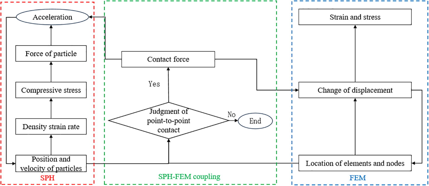
Figure 4: Calculation process of SPH–FEM contact algorithm
Here,
The assumption is made that SPH particles in the support domain of the FEM node exert contact forces on the node, and FEM nodes in the support domain of the SPH particles exert contact forces on the particles. The contact force between the FEM node and the SPH particles is expressed by Eq. (14).
Here,
This paper investigates a symmetric double-bearing horizontal cylindrical storage tank [22] depicted in Fig. 5. In the tank, the X-axis represents the vertical direction, the Y-axis signifies the axial direction, and the Z-axis denotes the horizontal transverse direction. One end of the horizontal storage tank is secured to the foundation using foot bolts, while the other end is also fixed to the foundation with foot bolts but allows sliding along the tank axis. The tank is constructed from Q345R steel with a wall thickness of 6 mm, and the saddle support is welded using 8 mm thick Q235A steel. The tank is designed to withstand earthquakes with a maximum acceleration of 0.1 g.

Figure 5: Horizontal storage tank size
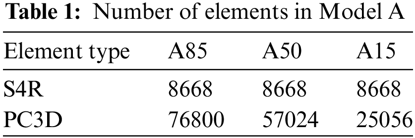
Abaqus software was utilized to develop a coupled SPH–FEM model (“Model A”) of the horizontal storage tank. The stored liquid was discretized into PC3D granular units representing SPH particles, while the tank and support were discretized using S4R four-node curved thin-shell units, depicted in Fig. 6. Initially, three models were created: A85, A50, and A15 corresponding to filling coefficients of 0.85, 0.5, and 0.15, respectively. These coefficients represent different storage capacities, with 0.85 indicating maximum capacity, 0.5 representing operating condition capacity, and 0.15 representing overhaul condition capacity. Additionally, a finite element model (“Model B”) of the horizontal storage tank was established using the equivalent mass method. The corresponding finite element models for the three filling factors were B85, B50, and B15. The equivalent mass method simplifies the tank and stored liquid by treating them as a centralized mass point connected to a cantilever beam to form an equivalent system. This model neglects the impact of liquid sloshing on the dynamic response of the tank. By comparing the dynamic responses of Model A and Model B under the same earthquake, the study examines the effects of factors such as stored liquid sloshing and stored liquid volume on the seismic response.

Figure 6: SPH–FEM model of the horizontal storage tank
The number of elements in Models A85, A50, and A15 is presented in Table 1.
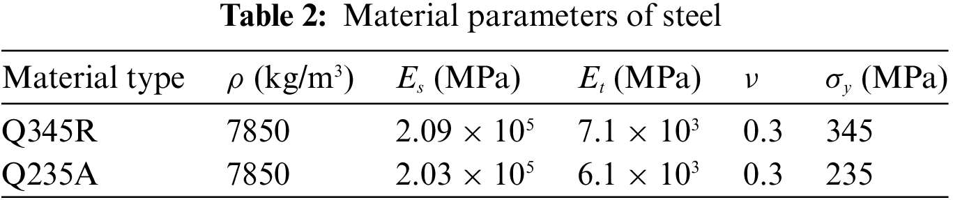
Both the tank and the saddle support are constructed from steel and modeled using a follow-hardening bilinear elastoplastic material model that adheres to the von Mises yield criterion, as depicted in Eq. (15).
Here,
The tank body is made of Q345R and the saddle support is made of Q235A. The mechanical property parameters for Q345R and Q235A are provided in Table 2.
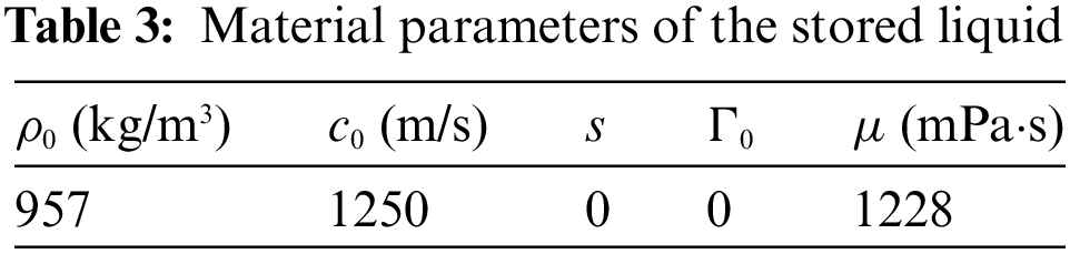
The stored liquid, considering the presence of a free liquid level, is described using the Mie–Grüneisen equation in the form of Us–Up, as presented in Eq. (16).
Here,
3.3 Model Rationality Verification
To assess the rationality of the coupled SPH–FEM model for horizontal storage tanks, a numerical simulation is conducted by subjecting “Model A85” to the El Centro (EW) ground vibration record with a peak acceleration of 0.2 g along the Z-direction. The results of the numerical simulation are compared with experimental data obtained from seismic simulation shaker tests on the tank, as referenced in the literature [22]. Fig. 7 shows a comparison between the numerically simulated dynamic time–history response of the tank and the experimental data. In Fig. 7a, the maximum relative error of the acceleration at the middle of the tank wall is found to be 18.85%, while in Fig. 7b, the maximum relative error of the strain value at the same location is 10.43%. Overall, the numerical simulation results exhibit closer agreement with the experimental data, thus substantiating the rationality of the coupled SPH–FEM model.

Figure 7: Calculation result verification
4 Selection and Spectral Characterization of Ground Vibration Records
4.1 Sources of Ground Vibration Records
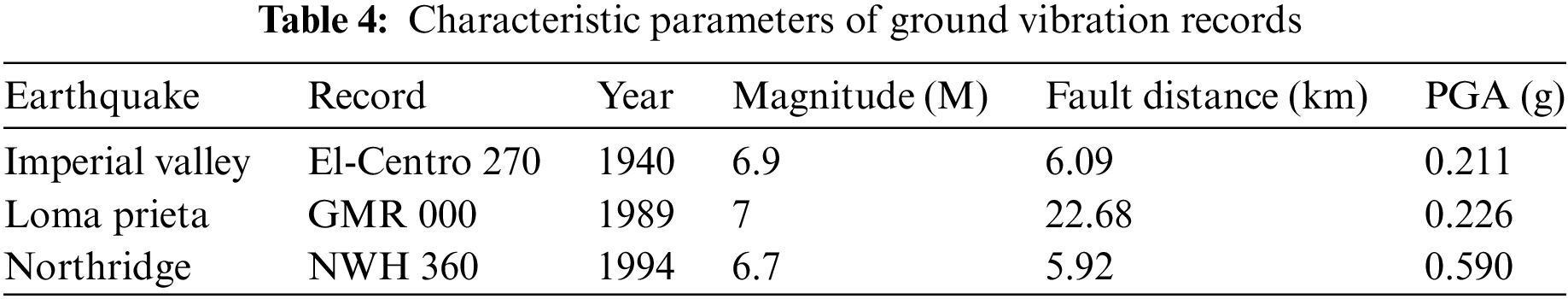
To investigate the dynamic responses of horizontal storage tanks during earthquakes, this study selected three ground vibration records from the strong earthquake database: El-Centro 270, GMR 000, and NWH 360. The characteristic parameters of the ground vibration records are shown in Table 4.
4.2 Comparison of Fourier Amplitude Spectra
The Fourier amplitude spectra of the three ground vibration records were obtained using the fast Fourier transform method, illustrating their distribution and proportion of vibration components at various frequencies, as depicted in Fig. 8. Fig. 8 demonstrates that El-Centro 270 is predominantly distributed within the 1–6 Hz range, GMR 000 within 1.5–7.5 Hz, and NWH 360 primarily within 0.5–4 Hz. Overall, the three ground vibration records exhibit a notable presence of high-frequency components.

Figure 8: Fourier amplitude spectra of the records
4.3 Comparison of Acceleration Response Spectra
Seismic acceleration response spectra reflect the impact of ground shaking spectral characteristics on the dynamic response of engineering structures. Fig. 9 illustrates the corresponding elastic response spectra, calculated for a 5% damping ratio, linear–elastic, single-degree-of-freedom system, with a peak acceleration of 0.2 g, under the influence of three ground shaking recordings.

Figure 9: Acceleration response spectra of the records
According to Fig. 9, the spectral profiles of El-Centro 270 are primarily concentrated within the period range of 0.2–0.5 s, with a peak acceleration of 0.560 g observed at a period of 0.58 s. Similarly, the spectra of GMR 000 exhibit a concentration range of 0.1–0.6 s, where the maximum acceleration reaches 0.887 g at a period of 0.14 s. Furthermore, the spectral values pertaining to NWH 360 are mainly concentrated within the period range of 0.2–1 s, with a peak acceleration of 0.737 g observed at a period of 0.68 s.
For this study, due to the lengthy duration of the chosen ground vibration records and the computational limitations, the input parameters consist of data ranging from the initial arrival of the acceleration value
Fig. 10 displays base shear along the Y-direction of Model A85 and Model B85 under the action of Centro-270. Similarly, Fig. 11 shows the top center displacement along the Y-direction of Model A50 and Model B50 under the action of GMR 000. Furthermore, Fig. 12 illustrates the base shear along the Z-direction of Model A15 and Model B15 under the action of NWH 360.

Figure 10: Base shear along the Y-direction of the tank with the liquid-fill factor of 0.85 under the action of Centro-270

Figure 11: Top center displacement along the Y-direction of the tank with the liquid-fill factor of 0.5 under the action of GMR 000

Figure 12: Base shear along the Z-direction of the tank with the liquid-fill factor of 0.15 under the action of NWH 360
Table 5 presents the maximum value of base shear and its corresponding occurrence time for the horizontal storage tank in the Z-direction. Similarly, Table 6 provides the maximum value of base shear and its occurrence time for the horizontal storage tank in the Y-direction. Additionally, Table 7 displays the maximum value of the top center displacement in the Z-direction and its time of occurrence. Finally, Table 8 shows the maximum value of the top center displacement in the Y-direction and its corresponding occurrence time.
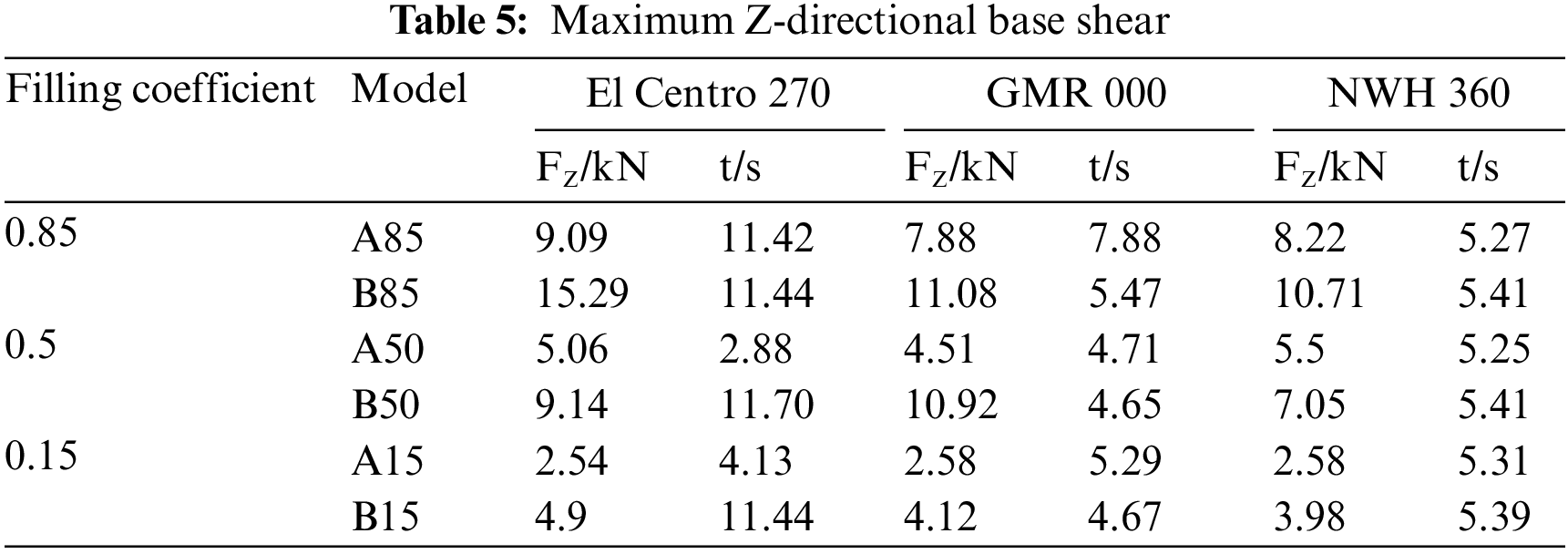
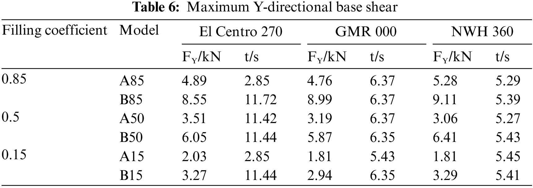
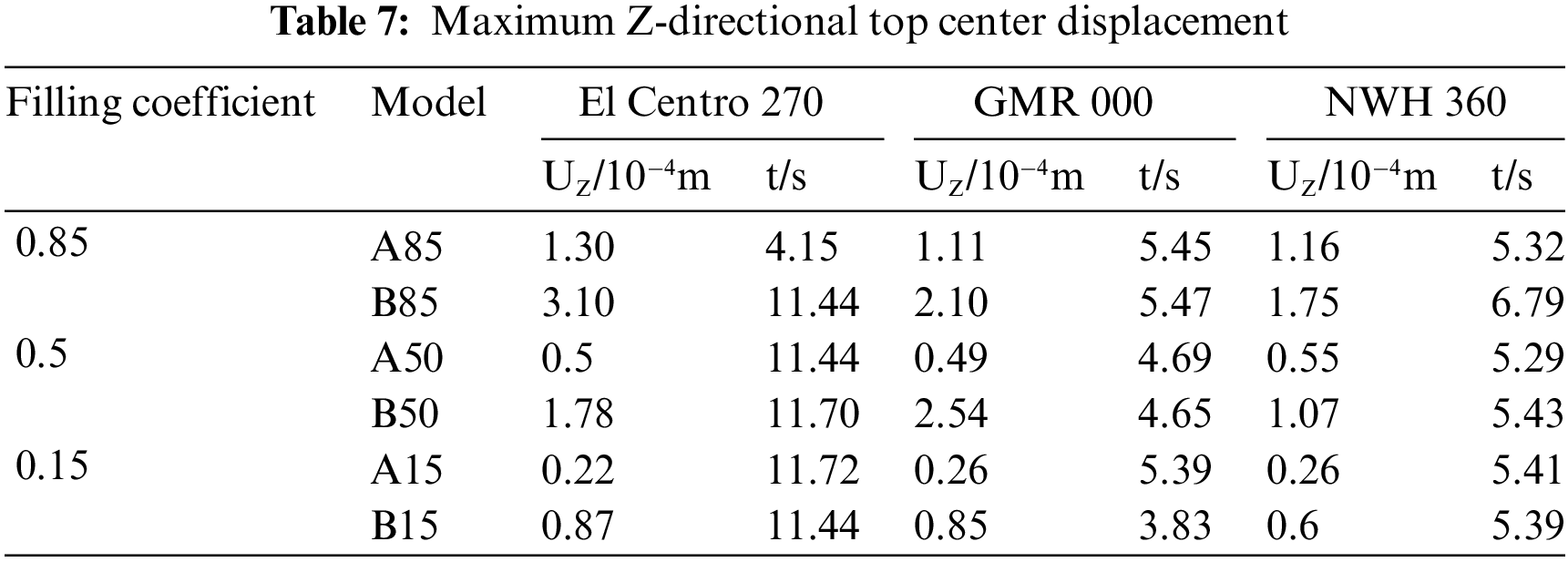
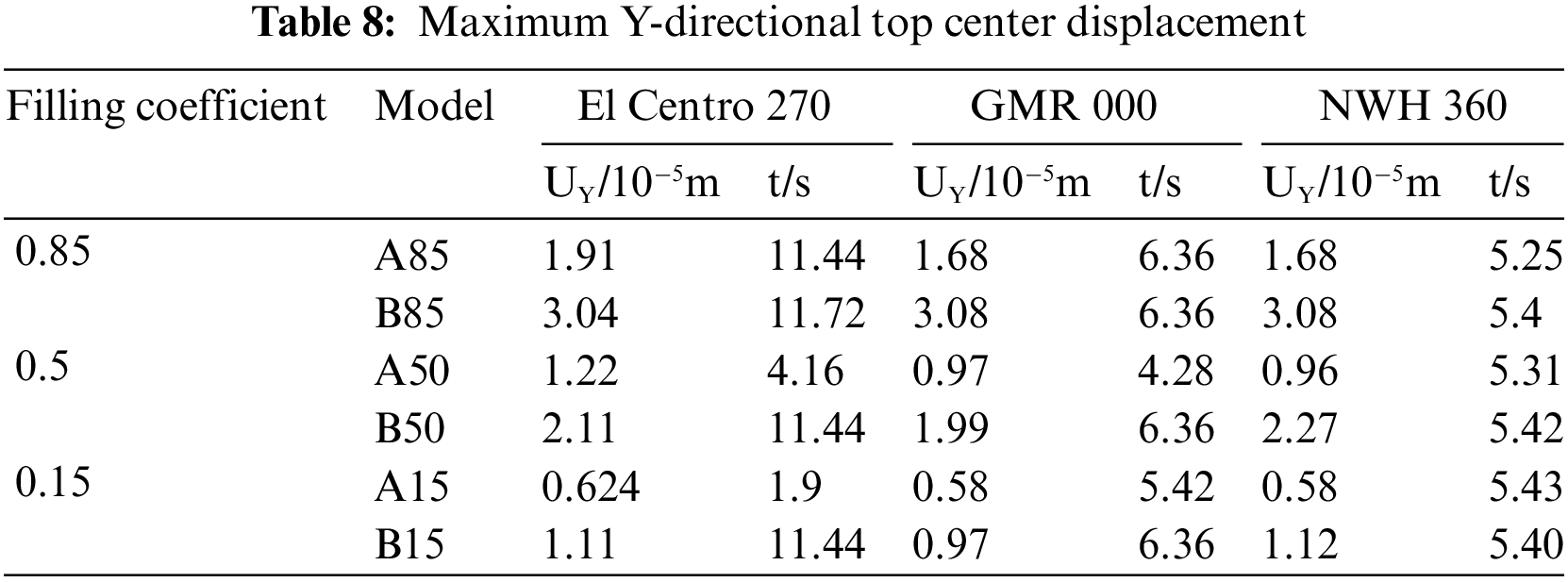
Table 9 presents the maximum values of the tank von Mises stresses and stored liquid sloshing wave heights during the occurrence of maximum base shear in various directions. Similarly, Table 10 provides the maximum values of tank stresses and stored liquid sloshing wave heights during the occurrence of maximum top center displacement in different directions for horizontal storage tanks with varying stored liquid volumes.
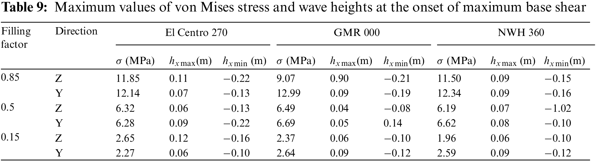
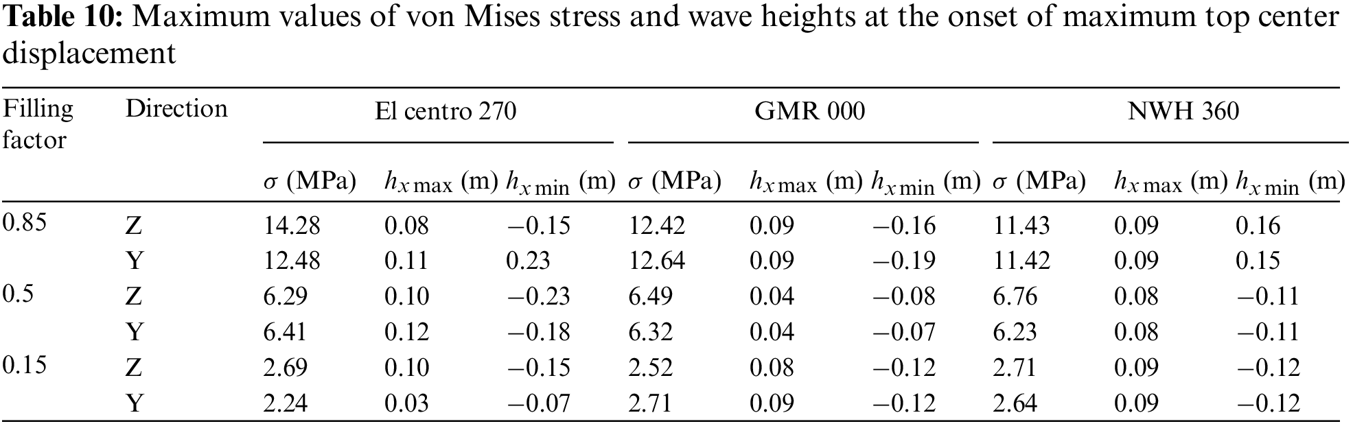
Fig. 13 displays the von Mises stress distribution of the tank at the moment of maximum top-center displacement in the Z-direction for Model A50 during the El Centro 270. Fig. 14 illustrates the wave height distribution of stored liquid sloshing at the moment of maximum top-center displacement in the Z-direction for Model A50 during the El Centro 270. An analysis of Fig. 13 reveals that the maximum von Mises stress in the horizontal storage tank predominantly occurs at the corners of the saddle support and the adjacent tank wall during the peak seismic response. Furthermore, an examination of Tables 9 and 10 demonstrates that as the liquid filling coefficient increases, the maximum von Mises stress in the horizontal storage tank also increases. However, it remains below the yield strength of both the tank wall and support materials. Therefore, no damage was observed in the tank or supporting structures during the earthquakes.

Figure 13: Tank von mises stress at maximum top-center displacement in the Z-direction

Figure 14: Wave height at maximum top-center displacement in the Z-direction for model A85
5.2 Influence of Stored Liquid Sloshing
The study investigated the ratios between the maximum base shear values of Model A and Model B in the Z-direction under different earthquakes and filling coefficients, depicted in Fig. 15. An analysis of Fig. 15 demonstrates that when the filling coefficient is 0.15, the average maximum base shear value of Model A in the Z-direction is 59.8% of that of Model B. Likewise, at a filling coefficient of 0.5, the average maximum base shear value of Model A in the Z-direction is 58.2% of Model B’s, while at a filling coefficient of 0.85, it increases to 69.1% compared to that of Model B. In summary, Model A demonstrates smaller base maximum shear values in the Z-direction compared to Model B.

Figure 15: Effect of stored liquid sloshing on the base shear in the Z-direction
The study investigated the ratios between the maximum Y-base shear values of Model A and Model B in the Y-direction under different earthquakes and filling coefficients, depicted in Fig. 16. An analysis of Fig. 16 demonstrates that when the filling coefficient is 0.15, the average maximum base shear value of Model A in the Y-direction is 59.5% of that of Model B. Likewise, at a filling coefficient of 0.5, the average maximum base shear value of Model A in the Y-direction is 53.3% of Model B’s, while at a filling coefficient of 0.85, it increases to 56.0% compared to that of Model B. In summary, Model A demonstrates smaller base maximum shear values in the Y-direction compared to Model B.

Figure 16: Effect of stored liquid sloshing on the base shear in the Y-direction
The study investigated the ratios between the maximum top-center displacement values of Model A and Model B in the Z-direction under different earthquakes and filling coefficients, depicted in Fig. 17. An analysis of Fig. 17 demonstrates that when the filling coefficient is 0.15, the average maximum top-center displacement of Model A in the Z-direction is 33.1% of that of Model B. Likewise, at a filling coefficient of 0.5, the average maximum top-center displacement of Model A in the Z-direction is 32.9% of Model B’s, while at a filling coefficient of 0.85, it increases to 53.7% compared to that of Model B. In summary, Model A demonstrates smaller top-center maximum displacement values in the Z-direction compared to Model B.

Figure 17: Effect of stored liquid sloshing on the top-center displacement in the Z-direction
The study investigated the ratios between the maximum top-center displacement values of Model A and Model B in the Y-direction under different earthquakes and filling coefficients, depicted in Fig. 18. An analysis of Fig. 18 demonstrates that when the filling coefficient is 0.15, the average maximum top-center displacement of Model A in the Y-direction is 55.9% of that of Model B. Likewise, at a filling coefficient of 0.5, the average maximum top-center displacement of Model A in the Y-direction is 49.6% of Model B’s, while at a filling coefficient of 0.85, it increases to 57.3% compared to that of Model B. In summary, Model A demonstrates smaller top-center maximum displacement values in the Y-direction compared to Model B.

Figure 18: Effect of stored liquid sloshing on the top-center displacement in the Y-direction
The analysis conducted above indicates that a SPH–FEM coupled model that takes into account the impact of stored liquid sloshing within a tank exhibits a lower seismic response compared to the conventional equivalent mass model. The analysis reveal that the equivalent mass method, which disregards the influence of liquid sloshing, overestimates the seismic response of horizontal storage tanks. It leads to an escalation in saddle base shear, tank axial stresses, tank tangential stresses, tank circumferential stresses, and the average stresses within the effective cross-section of the saddle bearings as predicted by the equivalent mass method. Consequently, seismic design based on the outcomes of the equivalent mass method analysis may necessitate an augmentation in the thickness of the tank wall and the number and size of ground bolts. This, in turn, can result in escalated construction expenses and unnecessary resource misallocation.
5.3 Influence of Stored Liquid Volume
In Fig. 19, the effects of various liquid filling coefficients on the maximum base shear in the Z-direction of Model A are compared. When the liquid filling coefficient is 0.5, the average value of the maximum base shear in the Z-direction is 1.96 times higher than when the liquid filling coefficient is 0.15. Similarly, when the liquid filling coefficient is 0.85, the average value of the maximum base shear in the Z-direction is 3.27 times higher compared to when the liquid filling coefficient is 0.15. In general, the maximum base shear in the Z-direction of Model A increases as the stored liquid volume increases.

Figure 19: Effect of liquid storage volume on the base shear in Z-direction
In Fig. 20, the effects of various liquid filling coefficients on the maximum base shear in the Y-direction of Model A are compared. When the liquid filling coefficient is 0.5, the average value of the maximum base shear in the Y-direction is 1.73 times higher than when the liquid filling coefficient is 0.15. Similarly, when the liquid filling coefficient is 0.85, the average value of the maximum base shear in the Y-direction is 2.65 times higher compared to when the liquid filling coefficient is 0.15. In general, the maximum base shear in the Y-direction of Model A increases as the stored liquid volume increases.

Figure 20: Effect of liquid storage volume on the base shear in Y-direction
Fig. 21 presents a comparison of the effects of various liquid filling coefficients on the maximum displacement at the top-center in the Z-direction of Model A. The results indicate that when the liquid filling coefficient is 0.5, the average value of the maximum displacement at the top-center in the Z-direction is 2.09 times higher compared to when the liquid filling coefficient is 0.15. Similarly, when the liquid filling coefficient is 0.85, the average value of the maximum displacement at the top-center in the Z-direction is 4.88 times higher than when the liquid filling coefficient is 0.15. In general, the maximum displacement at the top-center in the Z-direction of Model A increases with an increase in stored liquid.

Figure 21: Effect of stored liquid volume on the top-center displacement in the Z-direction
Fig. 22 presents a comparison of the effects of various liquid filling coefficients on the maximum displacement at the top-center in the Y-direction of Model A. The results indicate that when the liquid filling coefficient is 0.5, the average value of the maximum displacement at the top-center in the Y-direction is 1.76 times higher compared to when the liquid filling coefficient is 0.15. Similarly, when the liquid filling coefficient is 0.85, the average value of the maximum displacement at the top-center in the Y-direction is 2.95 times higher than when the liquid filling coefficient is 0.15. In general, the maximum displacement at the top-center in the Y-direction of Model A increases with an increase in stored liquid.

Figure 22: Effect of stored liquid volume on the top-center displacement in the Y-direction
The analysis above demonstrates that the seismic response of horizontal storage tanks under identical seismic conditions exhibits a gradual increase as the stored liquid volume increases.
This paper presents and validates a method for simulating the seismic response of horizontal storage tanks. The method efficiently captures strong nonlinear behaviors, including large sloshing of the free liquid surface, broken waves, and splashing. The method investigates the impact of liquid storage sloshing and volume on the seismic response of horizontal storage tanks. Additionally, design and operational recommendations for horizontal storage tanks are provided. The study yielded the following conclusions:
(1) A numerical simulation method for analyzing the seismic response of horizontal storage tanks using the coupled SPH–FEM algorithm is proposed in Abaqus software. The proposed method can provide dynamic responses, including acceleration, strain, stress, base shear, displacement, and stored liquid sloshing of the tank. We compare the simulation results with the test data, and an obtained error rate of 18.85% demonstrates the method’s good consistency with the test data, thus validating its rationality.
(2) The SPH-FEM coupling method is compared with the conventional equivalent mass method to analyze the impact of stored liquid sloshing and stored liquid volume on the base shear and top displacement of the tank. The results demonstrate that under the same seismic effect, the dynamic response obtained by the SPH–FEM coupling method is 53.3%~69.1% of that obtained by the conventional equivalent mass method, indicating that the SPH–FEM coupling method yields a smaller dynamic response compared to the conventional equivalent mass method.
(3) The dynamic response of a horizontal storage tank exhibits a gradual enhancement trend as the stored liquid volume increases under the same seismic action. The seismic response increases by 73%~388% for every 35% increase in stored liquid volume.
(4) The maximum von Mises stresses in the tank and supports during an earthquake with a peak acceleration of 0.2 g were significantly below the yield strength of the steel. As a result, both the tank and the supports of the horizontal storage tank remained undamaged. Under the influence of rare earthquakes, a horizontal storage tank shows excellent seismic performance with a high degree of seismic redundancy.
(5) In general, horizontal storage tanks exhibit favorable seismic performance and remain undamaged during rare earthquake events. However, the seismic design should fully consider the influence of liquid sloshing, and the SPH-FEM coupling model provides a more accurate depiction of the seismic response of horizontal storage tanks. Horizontal storage tanks located in earthquake-prone areas should carefully manage the filling coefficient to mitigate the elevated risk of earthquake damage.
Acknowledgement: The authors express their appreciation to Yuan Lyu for publishing the experimental data in the article. The authors acknowledge anonymous reviewers and journal editors whose comments resulted in an improvement of the paper.
Funding Statement: This research work was supported by Scientific Research Fund of Institute of Engineering Mechanics, China Earthquake Administration (Grant Nos. 2021B06, 2021C05) and Heilongjiang Natural Science Foundation Joint Guidance Project (Grant No. LH2021E122).
Author Contributions: The authors confirm contribution to the paper as follows: study conception and design: Peilei Yan, Endong Guo; data collection: Houli Wu, Liangchao Zhang; analysis and interpretation of results: Peilei Yan, Houli Wu; draft manuscript preparation: Peilei Yan. All authors reviewed the results and approved the final version of the manuscript.
Availability of Data and Materials: The data that support the findings of this study are available from the first author upon reasonable request.
Conflicts of Interest: The authors declare that they have no conflicts of interest to report regarding the present study.
References
1. Sinopec Group (2018). Code for seismic design of petrochemical steel facilities of special structures (GB50761-2018). Beijing, China. [Google Scholar]
2. European Committee for Standardisation (2006). Part 4: Silos, tanks and pipelines, Eurocode 8 (Annex A.5, CEN ENV-1998-4). Brussels, Belgium. [Google Scholar]
3. American Petroleum Institute (1995). Seismic design of storage tanks—Appendix E, welded steel tanks for oil storage (API Standard 650). Washington DC, USA. [Google Scholar]
4. Vern, S., Shrimalia, M. K., Bharti, S. D., Datta, T. K. (2021). Evaluation of the seismic response of liquid storage tanks. Earthquakes and Structures, 21(2), 205–217. [Google Scholar]
5. Güler, E., Alhan, C. (2021). Performance limits of base-isolated liquid storage tanks with/without supplemental dampers under near-fault earthquakes. Structures, 33(4), 355–367. [Google Scholar]
6. Akbari, J., Salami, O., Isari, M. (2020). Numerical investigation of the seismic behavior of unanchored steel tanks with an emphasis on the uplift phenomenon. Frattura ed Integrità Strutturale, 14(53), 92–105. [Google Scholar]
7. Rixon, K. L., Balamurugan, S. (2014). Seismic analysis of spherical vessel containing liquefied petroleum gas. International Journal of Science and Research, 2014(5), 1854–1856. [Google Scholar]
8. Adeyefa, O., Oluwole, O. O. (2013). Finite element modeling of seismic response of field fabricated liquefied natural gas (LNG) spherical storage vessels. Engineering, 5(6), 543–550. [Google Scholar]
9. Faltinsen, O. M., Timokha, A. N. (2012). Analytically approximate natural sloshing modes for a spherical tank shape. Journal of Fluid Mechanics, 703, 391–401. [Google Scholar]
10. Moiseev, N. N., Petrov, A. A. (1966). The calculation of free oscillations of a liquid in a motionless container. Advances in Applied Mechanics, 9, 91–154. [Google Scholar]
11. Fox, D., Kuttler, J. R. (1981). Upper and lower bounds for sloshing frequencies by intermediate problems. Zeitschrift für angewandte Mathematik und Physik, 32, 667–682. [Google Scholar]
12. Mciver, P. (1989). Sloshing frequencies for cylindrical and spherical containers filled to an arbitrary depth. Journal of Fluid Mechanics, 201, 243–257. [Google Scholar]
13. Mciver, P., Mciver, M. (1993). Sloshing frequencies of longitudinal modes for a liquid contained in a trough. Journal of Fluid Mechanics, 252, 525–541. [Google Scholar]
14. Hasheminejad, S. M., Aghabeigi, M. (2009). Liquid sloshing in half-full horizontal elliptical tanks. Journal of Sound and Vibration, 324(1–2), 332–349. [Google Scholar]
15. Hasheminejad, S. M., Aghabeigi, M. (2011). Transient sloshing in half-full horizontal elliptical tanks under lateral excitation. Journal of Sound and Vibration, 330(14), 3507–3525. [Google Scholar]
16. Nezami, M. T., Mohammadi, M. M., Oveisi, A. (2014). Liquid sloshing in a horizontal circular container with eccentric tube under external excitation. Shock and Vibration, 2014, 1–15. [Google Scholar]
17. Kolaei, A., Rakheja, S., Richard, M. J. (2014). Range of applicability of the linear fluid slosh theory for predicting transient lateral slosh and roll stability of tank vehicles. Journal of Sound and Vibration, 333(1), 263–282. [Google Scholar]
18. Hasheminejad, S. M., Soleimani, H. (2017). An analytical solution for free liquid sloshing in a finite-length horizontal cylindrical container filled to an arbitrary depth. Applied Mathematical Modelling, 48, 338–352. [Google Scholar]
19. Lyu, Y., Jiangang, S., Sun, Z., Lifu, C., Zhen, W. (2020). Simplified mechanical model for seismic design of horizontal storage tank considering soil-tank-liquid interaction. Ocean Engineering, 198(6), 106953. [Google Scholar]
20. Han, Y., Zhu, X., Li, T., Guo, W., Pan, L. (2021). A semi-analytical study of the three-dimensional liquid sloshing in a horizontal cylindrical tank with an arbitrary liquid depth. Ocean Engineering, 238, 109722. [Google Scholar]
21. Han, Y., Zhu, X., Guo, W., Li, T., Zhang, S. (2022). Coupled vibration analysis of partially liquid-filled cylindrical shell considering free surface sloshing. Thin-Walled Structures, 179, 869–897. [Google Scholar]
22. Lyu, Y., Sun, J., Sun, Z., Cui, L., Wang, Z. (2020). Seismic response calculation method and shaking table test of horizontal storage tanks under lateral excitation. Earthquake Engineering & Structural Dynamics, 50(2), 619–634. [Google Scholar]
23. Zhu, H. P., Tang, Z. A., Luo, H. (2023). Feasibility analyses of negative-stiffness dampers for seismic performance enhancement of a base-isolated liquid storage tank. Soil Dynamics and Earthquake Engineering, 164, 107575. [Google Scholar]
24. Zhu, H. P., Tang, Z. A., Luo, H. (2023). Seismic performance of a base-isolated flexible liquid storage tank equipped with a novel rate-independent damping device. Structures, 51, 215–225. [Google Scholar]
25. Drosos, G. C., Dimas, A. A., Karabalis, D. L. (2008). Discrete models for seismic analysis of liquid storage tanks of arbitrary shape and fill height. Journal of Pressure Vessel Technology, 130(4), 041801. [Google Scholar]
26. Karamanos, S. A., Papaprokopiou, D., Platyrrachos, M. A. (2009). Finite element analysis of externally-induced sloshing in horizontal-cylindrical and axisymmetric liquid vessels. Journal of Pressure Vessel Technology, 131(5), 051301. [Google Scholar]
27. Saghi, H., Ketabdari, M. J. (2012). Numerical simulation of sloshing in rectangular storage tank using coupled FEM-BEM. Journal of Marine Science and Application, 11, 417–426. [Google Scholar]
28. Ketabdari, M. J., Saghi, H. (2013). Parametric study for optimization of storage tanks considering sloshing phenomenon using coupled BEM-FEM. Applied Mathematics and Computation, 224, 123–139. [Google Scholar]
29. Saghi, H. (2016). The pressure distribution on the rectangular and trapezoidal storage tanks’ perimeters due to liquid sloshing phenomenon. International Journal of Naval Architecture and Ocean Engineering, 8(2), 153–168. [Google Scholar]
30. Lucy, L. B. (1977). A numerical approach to the testing of the fission hypothesis. The Astronomical Journal, 8(12), 1013–1024. [Google Scholar]
31. Gingold, R. A., Monaghan, J. J. (1977). Smoothed particle hydrodynamics: Theory and application to non-spherical stars. Monthly Notices of the Royal Astronomical Society, 181, 375–389. [Google Scholar]
32. Hasanpour, A., Istrati, D., Buckle, I. G. (2021). Coupled SPH-FEM modeling of tsunami-borne large debris flow and impact on coastal structures. Journal of Marine Science and Engineering, 9(10), 1068. [Google Scholar]
33. Du, Y., Ma, L., Zheng, J., Zhang, F., Zhang, A. (2016). Coupled simulation of explosion-driven fracture of cylindrical shell using SPH-FEM method. International Journal of Pressure Vessels and Piping, 139, 28–35. [Google Scholar]
34. Hao, H., Hao, Y., Li, J., Chen, W. (2016). Review of the current practices in blast-resistant analysis and design of concrete structures. Advances in Structural Engineering, 19(8), 1193–1223. [Google Scholar]
35. Scazzosi, R., Giglio, M., Manes, A. (2020). FE coupled to SPH numerical model for the simulation of high-velocity impact on ceramic based ballistic shields. Ceramics International, 46(15), 23760–23772. [Google Scholar]
36. Anas, S. M., Ansari, M. I., Alam, M. (2020). Performance of masonry heritage building under air-blast pressure without and with ground shock. Australian Journal of Structural Engineering, 21(4), 329–344. [Google Scholar]
37. Ma, J. X., Ma, L., Wei, C., Hu, Y., Zhao, Y. (2020). Dynamic analysis of liquid sloshing in spherical tank based on SPH method. Chinese Space Science and Technology, 40(1), 7–18. [Google Scholar]
Cite This Article
 Copyright © 2024 The Author(s). Published by Tech Science Press.
This work is licensed under a Creative Commons Attribution 4.0 International License , which permits unrestricted use, distribution, and reproduction in any medium, provided the original work is properly cited.
 Downloads
 Citation Tools