
 Submit a Paper
 Propose a Special lssue
 Open Access
ARTICLE

Finite Element Simulation Analysis of a Novel 3D-FRSPA for Crawling Locomotion
1 College of Mechanics and Materials, Hohai University, Nanjing, 211100, China
2 Department of Fundamental, Ma’anshan University, Ma’anshan, 243100, China
* Corresponding Authors: Bingzhu Wang. Email: ; Xiangrui Ye. Email:
Computer Modeling in Engineering & Sciences 2024, 139(2), 1401-1425. https://doi.org/10.32604/cmes.2024.047364
Received 03 November 2023; Accepted 19 December 2023; Issue published 29 January 2024
 View Full Text
 Download PDF
Abstract
A novel three-dimensional-fiber reinforced soft pneumatic actuator (3D-FRSPA) inspired by crab claw and human hand structure that can bend and deform independently in each segment is proposed. It has an omni-directional bending configuration, and the fibers twined symmetrically on both sides to improve the bending performance of FRSPA. In this paper, the static and kinematic analysis of 3D-FRSPA are carried out in detail. The effects of fiber, pneumatic chamber and segment length, and circular air chamber radius of 3D-FRSPA on the mechanical performance of the actuator are discussed, respectively. The soft mobile robot composed of 3D-FRSPA has the ability to crawl. Finally, the crawling processes of the soft mobile robot on different road conditions are studied, respectively, and the motion mechanism of the mobile actuator is shown. The numerical results show that the soft mobile robots have a good comprehensive performance, which verifies the correctness of the proposed model. This work shows that the proposed structures have great potential in complex road conditions, unknown space detection and other operations.Keywords
The rigid crawling mobile robots inspired by biological structure are widely used in various industrial practices and auxiliary equipment, such as cargo handling robots, lower limb exoskeleton rehabilitation robots, etc. It has brought great help to industrial production and rehabilitation medical treatment [1,2]. However, the traditional rigid mobile robot is limited by the size of the connecting rod and connecting mechanism, so its flexibility is not enough. In order to improve flexibility, it is necessary to improve the degree of freedom of the structure or match it with complex control algorithms, which increases the research and development costs and limits the scope of application [3,4]. Moreover, for complex road conditions with obstacles, the mobile robot may not be able to pass the specified locomotion path smoothing, thus limiting its corresponding functions. Moreover, due to the structural limitations of rigid links, mobile robots such as exoskeleton rehabilitation robots have poor environmental adaptability, safety and reliability [5,6]. Therefore, in order to overcome the shortcomings of the rigid mobile robot and improve the interaction ability with the multi-environment, the robot with high security and reliability and low price has a huge research prospect.
Natural creatures, such as animals and plants, provide a lot of design inspiration to human beings, which greatly promotes the development of soft mobile robots [7,8], and have become the current research hotspot and development frontier. The soft mobile robot usually consists of a soft actuator and a rigid bracket. Among them, the actuator composed of flexible materials can carry out large deformation movement, which is driven by a variety of modes, such as pneumatic [9], combustion drive [10], shape memory alloy (SMA) [11] and so on. However, the risk of combustion drive is high, and the displacement is not easy to control. SMA driven by electricity has the disadvantage of a low power ratio. Due to the characteristics of large deformation of soft materials, the energy utilization rate of pneumatic actuator is also a problem that needs to be paid attention to. In contrast, pneumatic driven actuators have the characteristics of fast response speed, high power density, low cost and easy control [12,13]. Therefore, pneumatic drive is still widely used in the field of soft robots. By changing the position and size of the air chamber structure and volume of the actuator, different motion modes can be formed, and the soft mobile robot can be driven to complete specific locomotion, such as crawling, turning locomotion of animals [14,15]. For example, the caterpillar crawls in the bow [16] and the earthworm wriggle [17], which have strong maneuvering ability and strong adaptability to the environment. Due to the cushioning effect of flexible materials, which further improves the safety in the operation process, soft mobile robots can be widely used in post-disaster rescue, pipeline detection and other fields [18,19].
The main body of a pneumatic driven actuator is mainly composed of soft materials (such as rubber, silicone, etc.), which has great flexibility. Its own body shape and movement can better adapt to the external environment, with a wide range of applications [20,21]. With the rapid development of bionics, many actuators with novel structures have been fully studied. Onal et al. [22] developed a snake-like soft robot, which consists of four bidirectional flexible parts. But it does not have autonomous steering capability. Rafsanjani et al. [23] proposed a snake-like soft robot based on the texture structure of snake scale skin and the Kirigami principle. Must et al. [24] designed a soft robot with variable stiffness to mimic the tentacles according to the internal penetration principle of plant tentacles, which can complete the extension locomotion along the rods. Zhang et al. [25] introduced an inchworm-like soft actuator, which has two functions of crawling and climbing and can complete locomotion in both terrestrial and underwater environments. Jeong et al. [26] designed a bellows shaped soft actuator with multiple air chambers according to the structure of the human hand, which has multiple bending functions and a high degree of fit with it. Although the soft actuator with bellows multi-chamber structure can improve its bending performance to a certain extent, due to the low stiffness of the soft material, it will lead to the radial main elongation ratio
The soft mobile robot, composed of a soft actuator, can enter narrow spaces that traditional robots cannot enter by virtue of its good bending performance and flexibility. Therefore, it can be widely used in various engineering scenarios [30]. Chen et al. [8] produced a three-segment soft mobile robot with multiple air chambers, which has two motion modes: straight line and cross. The coordinated motion of each segment enables it to complete obstacle avoidance. However, the linear motion mode does not have the ability to turn or lateral crawl. Wang et al. [14] proposed a type of Ω multi-segment soft crawling robot modeled on inchworm, in which all segments complete forward and turn locomotion, and the locomotion of each locomotion can be independent of each other. The maximum forward speed is 5.11 mm/s and the maximum turning speed is 0.76 degree/s. But whether it has an obstacle avoidance function is not given in the motion mechanism. Yeh et al. [19] designed a soft crawling robot that could be used for pipeline inspection. It could move quickly in horizontal and vertical pipelines, but its compact structure could not make it move in other complex terrains. Shepherd and Tolley et al. [31,32] first proposed a quadruped pneumatic crawling robot without rigid connectors, which has two gaits, wavy and crawling, and can complete corresponding locomotion across obstacles according to the inflated state of each foot. But lack of kinematic mechanism analysis. Fei et al. [33] built a modular soft mobile robot composed of three deformable spherical units. By controlling the input pressure, the diameter of each module is changed so as to complete the locomotion in narrow or low complex channels. But the same as [8], it cannot turn and walk laterally. Compared to our previous proposal of a soft actuator with a multi-segment corrugated tube structure [34]. The multi-segment three-dimensional-fiber reinforced soft pneumatic actuator (3D-FRSPA) designed in this paper, while ensuring the same bending and axial elongation functions, simplifies its internal air chamber structure from a complex corrugated tube structure to a cylindrical air chamber structure. The 3D-FRSPA is wrapped with double-sided symmetrical fiber lines on the outside, limiting radial deformation and improving the deformation ability of bending and axial elongation so that the energy generated by the input air pressure is more used for the deformation of the actuator.
The main contributions of this paper are as follows: (1) Based on the inspiration of bionics, a novel multi-segment 3D-FRSPA with independent and omni-directional bending performance is designed. (2) The theoretical models of statics and kinematics for single and multi-segments 3D- FRSPA are given, respectively. (3) The effects of fibers, length of the air chamber and segment, radius of circular air chamber of 3D-FRSPA on the mechanical performance of the actuator are discussed, respectively. (4) The crawling soft robots composed of three-segment of 3D-FRSPAs are numerically studied, and the simulation results of crawling in the different spaces are given, respectively.
The remainder of the paper is organized as follows. In Section 2, the new multi-segment 3D-FRSPA is introduced. Section 3 deduces the theoretical models of statics and kinematics of 3D-FRSPA in detail. In Section 4, a detailed parameter analysis is carried out. The bending behavior under different parameters is discussed. In Section 5, the application simulation of crawling of soft mobile robots in different environments is given. Finally, Sections 6 and 7 contain the discussions, main conclusions, and outlook for this paper.
In real nature or world, there are a large number of creatures with multi-joint lower limb structures, such as snow crab claw’s lower limb [35] and human fingers [36] structures. The above structures have three or more segments, and each segment can rotate freely to achieve the functions of crawling or grasping objects and other functions. Inspired by the above biological structure and its related sizes, this paper proposes a multi-segment 3D-FRSPA as shown in Fig. 1. It is composed of three segments (Fig. 1a). The structural sizes of each segment can be adjusted according to the actual application scenario, and the sizes between segments are independent of each other. Each segment is connected with a bellow-shaped joint (Fig. 1b). By adjusting the number of bellow bulges of the joint, the bending trajectory of SPA can be changed [34]. In the non-joint area, that is, in the bending part of the soft body, two equal length and symmetrical fiber lines are wound along the axis (Fig. 1e). Thus, 3D-FRSPA is formed. FRSPA makes up for the fact that the structure of multi-joint organisms in the real world can only bend in one direction and cannot extend axially. The application scope of the crawling robot is greatly expanded by reasonably controlling the input air pressure and selecting the appropriate air chamber position. Such as crossing narrow channels, etc. By winding the fibers, the radial deformation is limited, the stiffness of the 3D-FRSPA is increased, the bending angle is larger, and the utilization efficiency of air pressure energy is improved.
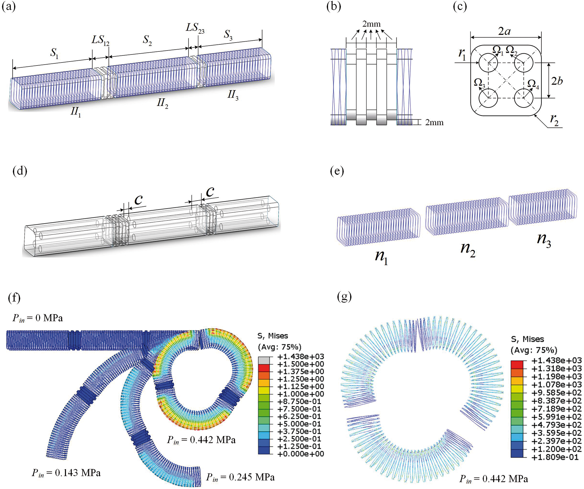
Figure 1: Numerical modeling of the proposed FRSPA. (a) Geometric details of the FRSPA. (b) Geometric sizes of connecting joints. (c) Cross section geometric details of FRSPA, where
Fig. 1 shows the numerical model of 3D-FRSPA. Its actuating principle is as follows: different air chambers are inflated to produce bending or elongation deformation. To simplify the description, the four air chambers are labeled as
In Fig. 1a, each segment are denoted as
In this section, the theoretical expression of the proposed 3D-FRSPA structure is derived, and the statics kinematics are analyzed. The bending models of single- and multi-segment 3D-FRSPA are presented, the accuracy of the models is verified, and the errors of different mesh structures are analyzed to ensure calculation accuracy and improve calculation efficiency.
Since the bending motion of FRSPA is a nonlinear large deformation caused by
where
where
It can be seen from Section 2 that the 3D-FRSPA of the
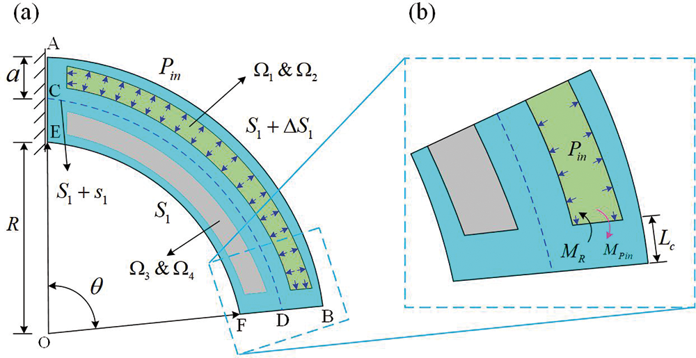
Figure 2: Bending theoretical model of the designed FRSPA. (a) The actuator bends when the
Due to the incompressibility of silicon rubber material, the total volume of silica gel remains unchanged before and after inflation.
When
where
After inflation, the chamber
Then, we can get the volume of the air chamber
where
Since gravity has little effect on the 3D actuator relative to the input air pressure
Since the bending angle
For multi-segment FRSPA, the joint connected is a non-air chamber connection part without rotation function. Therefore, when the condition of the position of
3D-FRSPA is composed of three segments, and each segment has different bending configurations. Therefore, the total end pose expression is the vector product of each segment. According to [35], the explicit expression of the end position and posture of the three-segment 3D-FRSPA proposed in this paper is
where
In Eqs. (10) and (11),
For the soft crawling robot, it belongs to multiple lower limbs fixed on a rigid support, and the position and speed of the initial end face of each soft body are the same as that of the rigid support, while the position and initial speed of the rigid support are known, so the inverse kinematics expression of 3D-FRSPA is not given here.
3.3 Finite Element Analysis of Theoretical Model
The consistency of the theoretical model and numerical calculation can ensure the rationality of the results of the FRSPA designed, and can provide accurate data reference for the follow-up locomotion mechanism of the soft crawling robot. In this section, the FRSPA of single and multi-segment FRSPA in Fig. 1a will be verified numerically. The finite element model of the FRSPA was established and analyzed by ABAQUS/Standard. For the soft part of the model, the element type was selected as C3D10H, the material constant was set as

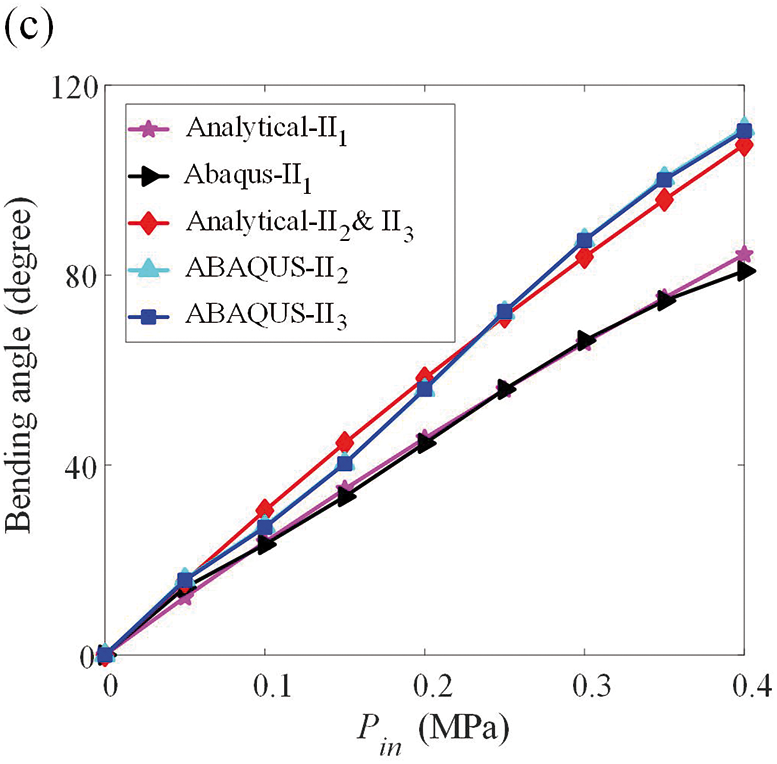
Figure 3: Verification of ABAQUS results and theoretical values of FRSPA. The increased step size of
The structure of FRSPA has a high degree of nonlinearity, so it is necessary to consider the calculation efficiency while ensuring the accuracy of numerical calculation. Due to the element properties of C3D10H and B32 in ABAQUS, it is not possible to partition the number of elements specified for FRSPA accurately. Therefore, the method of controlling the number of elements by adjusting the mesh boundary size is adopted. The specific element boundary size and the total number of elements are shown in Table 1, where lsoft-m and lfibre-m represent the mesh boundary size of soft and fiber, respectively. NeSsoft and NeSfibre denote the total number of elements of single segment soft and two fibers, respectively. NeMsoft and NeMfibre indicate the total number of elements of multi-segment soft and two fibers, respectively. There is a one-to-one correspondence between lsoft-m and lfibre-m, and only the size of the mesh boundary of lsoft-m is indicated later. They increase from 1 and 0.3 mm, respectively, and the step size increases from 0.5 and 0.2 mm, respectively. Meanwhile, in order to ensure accuracy, the maximum values are set to 5 and 1.9 mm, respectively.

The experimental setup involves an Intel(R) Core(TM) i5-6500 CPU with 16 GB RAM. lsoft-m = 1 mm and lfibre-m = 0.3 mm were used as reference results for accuracy verification. Define the
where
The computation time of error analysis cloud chart and boundary size of each grid is shown in Figs. 4 and 5, respectively. It can be seen from Fig. 4 that for single and multi-segments of FRSPA, the error will gradually increase with the increase of mesh boundary size and input pressure
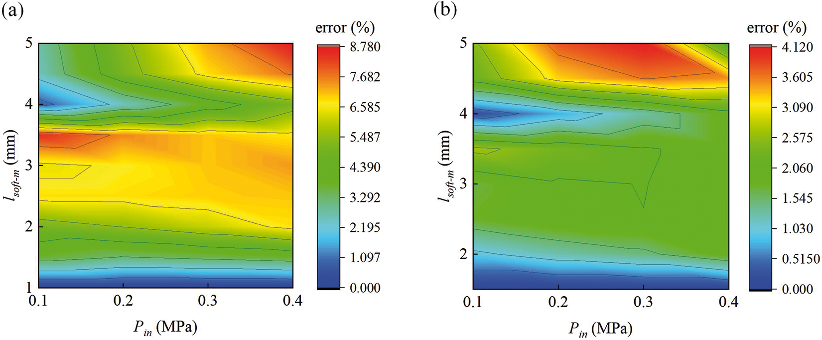
Figure 4: Mesh error analysis nephogram of FRSPA. The input air pressure
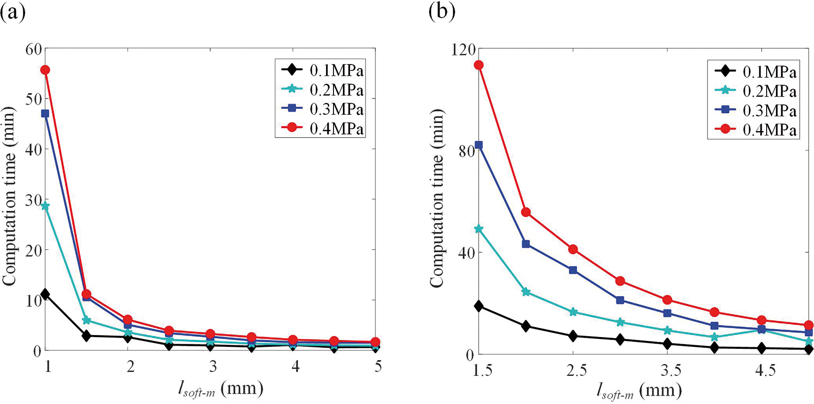
Figure 5: Computation time of FRSPA for different mesh sizes. (a) Single segment. (b) Multi-segment
4 Mechanical Performances of the FRSPA
The fiber reinforced soft actuator are sensitive to structural parameters. In order to better characterize the mechanical properties of FRSPA, this section systematically analyzes the fibers, air chamber shape and segment length, and circular air chamber radius.
In this Section, the influence of fibers with different turns on the bending performance of 3D-FRSPA is first studied. Three different types of fiber winding methods for SPA were designed, as shown in Fig. 6a. They are non wound fibers, symmetrically wound for 30 turns in all three segments, and the number of turns in each segment is taken as
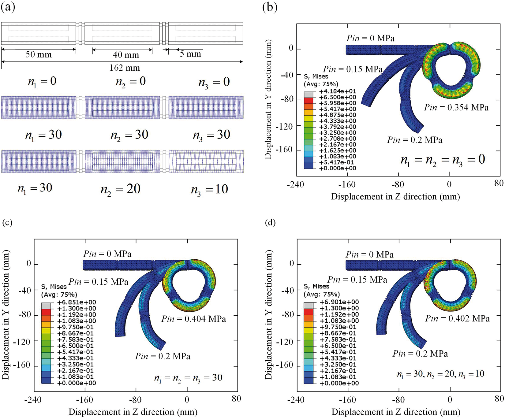
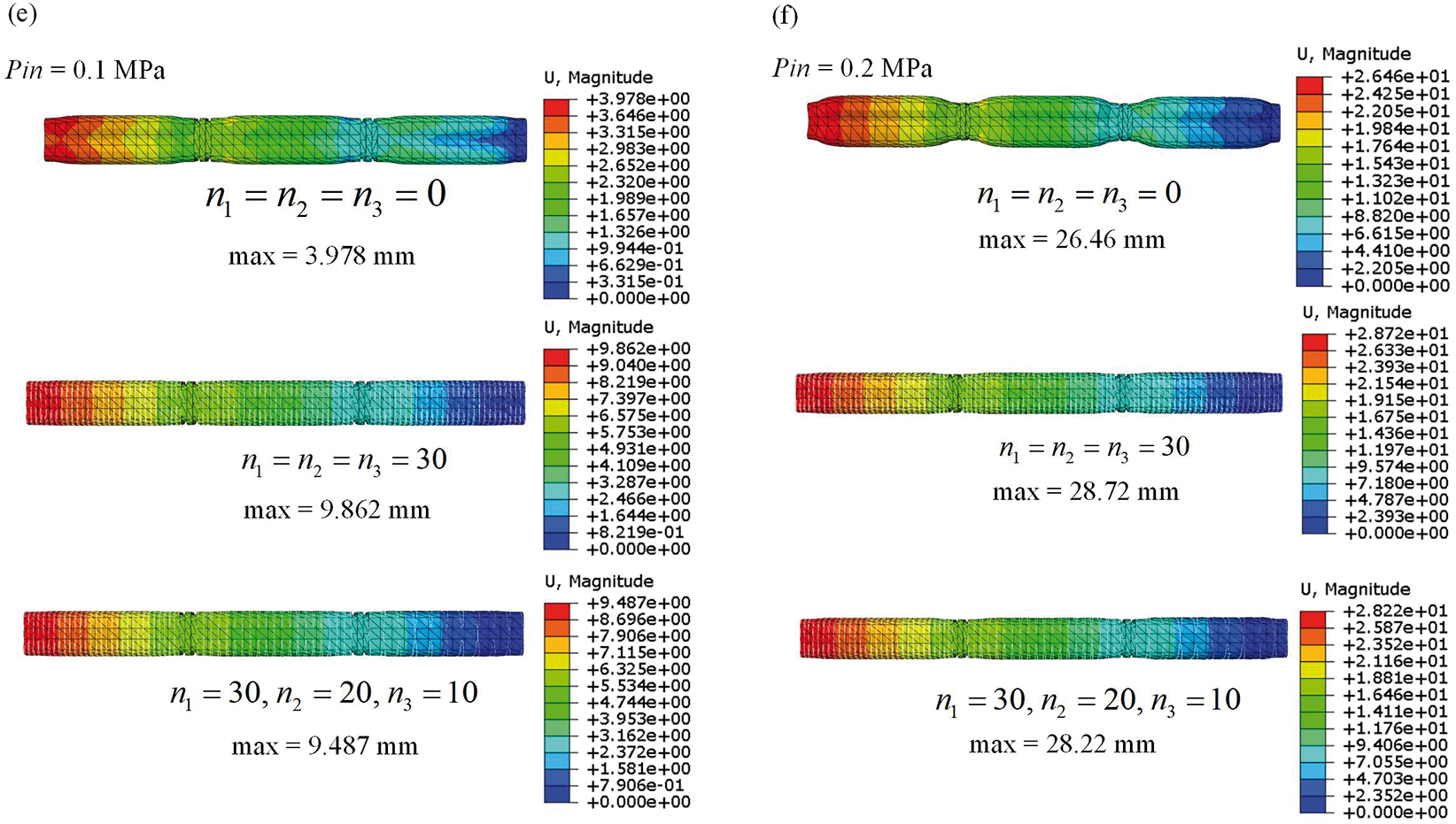
Figure 6: Numerical results of the 3D-FRSPA of different fibers. (a) Geometric details of the 3D-FRSPA. Cloud diagram of bending configuration and stress distribution when applying different
It can be clearly seen from Figs. 6b–6d that the SPA wrapped with fibers has a larger bending angle compared to the SPA without fiber winding when Pin is applied at the same time. When three types of SPA reach 360° bending, the required Pin values are 0.354, 0.404 and 0.402 MPa, respectively. Therefore, when Pin is too large, due to the limitation of fiber deformation, more air pressure is needed to achieve 360° bending, but for crawling motion, SPA is not required to achieve 360° bending. When the input air pressure is not too high, the fiber wrapped SPA has better bending performance.
For the axial elongation analysis of SPA, it can be seen from Figs. 6e and 6f that fiber reinforced SPA has a greater elongation than non fiber wrapped SPA when the same Pin is applied. When the number of fiber turns in all three segments is 30, the elongation is greater than that of SPA with three segments of turns of 30, 20, and 10, respectively. However, the radial deformation of SPA without fibers will gradually increase with increasing air pressure, which will lead to additional consideration of lateral spatial interference in subsequent crawling movements. Fiber reinforced SPA does not need to consider this problem. Therefore, fiber wound SPA has better axial elongation ability. In summary, from the quantitative comparison results in Fig. 6, it can be seen that fiber-reinforced SPA has better bending and axial deformation ability.
4.2 Pneumatic Chamber and Segment Length
In this section, we will study the influence of the pneumatic chamber and the segment length on the bending performance of the multi-segment FRSPA. Firstly, the research object is the chamber length,
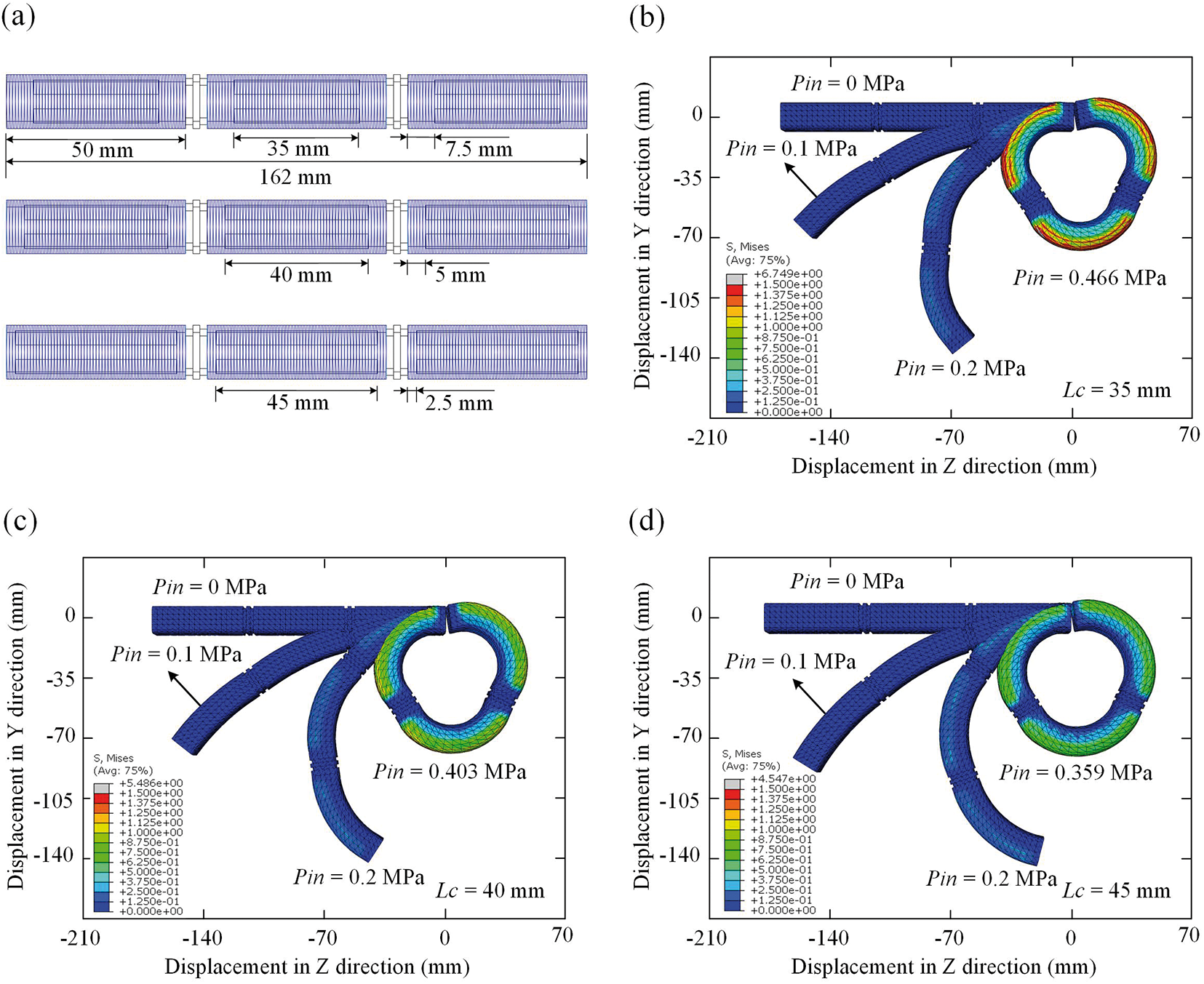
Figure 7: Numerical results of the 3D-FRSPA of different of pneumatic chamber. (a) Geometric details of the 3D-FRSPA. Cloud diagram of bending configuration and stress distribution when applying different
It can be seen from Figs. 7b–7d that when the same input air pressure
In order to improve the applicability and generality of the 3D-FRSPA, different from the segment lengths used for different air chamber lengths, the segment lengths were taken as
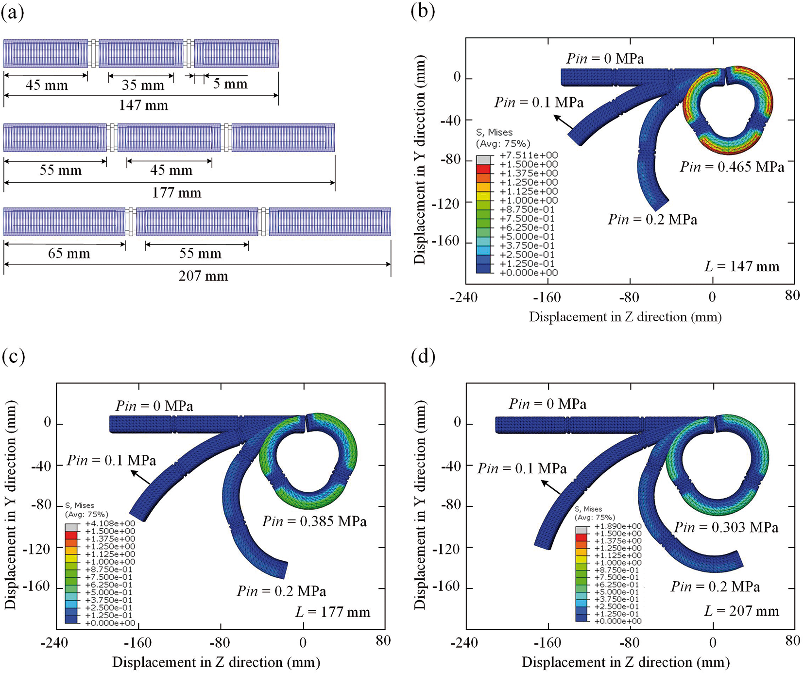
Figure 8: Numerical results of the 3D-FRSPA of different length of segment. (a) Geometric details of the 3D-FRSPA. Cloud diagram of bending configuration and stress distribution when applying different
It can be seen from the numerical results that when the same
4.3 Radius of the Circular Chamber
Next, we investigate the influence of the radius of
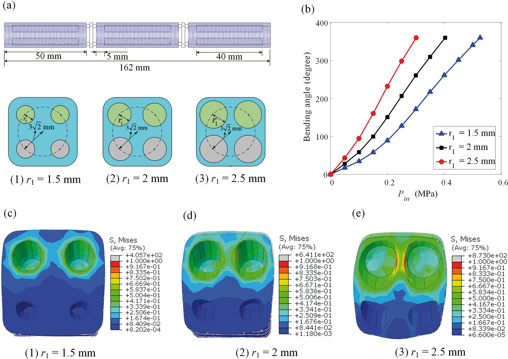
Figure 9: Numerical results of the 3D-FRSPA of different radius of the circular chamber. (a) Schematic of geometric details for
It can be seen from Fig. 9 that the larger the radius
5 Crawling Analysis in Different Environments
In the above sections, the theoretical model of 3D-FRSPA proposed was verified, and the appropriate mesh structure was proposed. At the same time, the parameters of single and multi-segments were analyzed in detail, and the static and dynamic analysis was carried out. According to the conclusions of the previous sections, this section will design two types of crawling locomotion under different road environments to verify the advantages and application of the soft crawling robot proposed in this paper.
The Section Introduction gives the research motivation and importance of flexible and multifunctional soft crawling robots. This section proposes a soft crawling robot composed of rigid support with a lightweight optimization design and eight lower limbs. According to Eq. (11) and the locomotion rule of biological gait, the horizontal and vertical spacing is set as lEF = 50 mm and lAE = 130 mm, respectively, and the structure is shown in Fig. 10. A single multi-segment FRSPA consists of three sections, with a total length of 166 mm. Figs. 10a and 10b show the geometric details of the soft lower limb and the rigid support and the schematic diagram of its structure. The eight three-segment FRSPA are numbered as A, B, ..., D. Fig. 10c shows a flat road with a size of 600 mm × 300 mm, placed horizontally, used to simulate the barrier-free crawling simulation of a soft crawling robot.
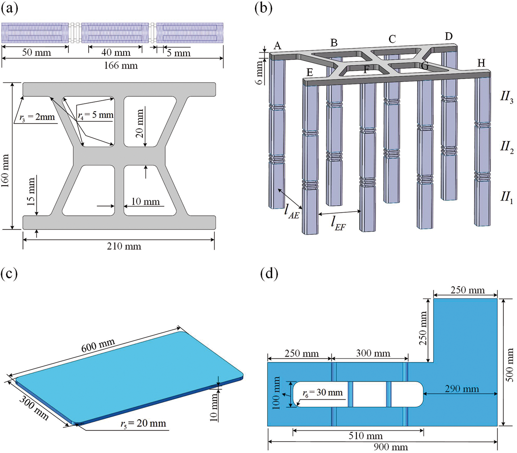
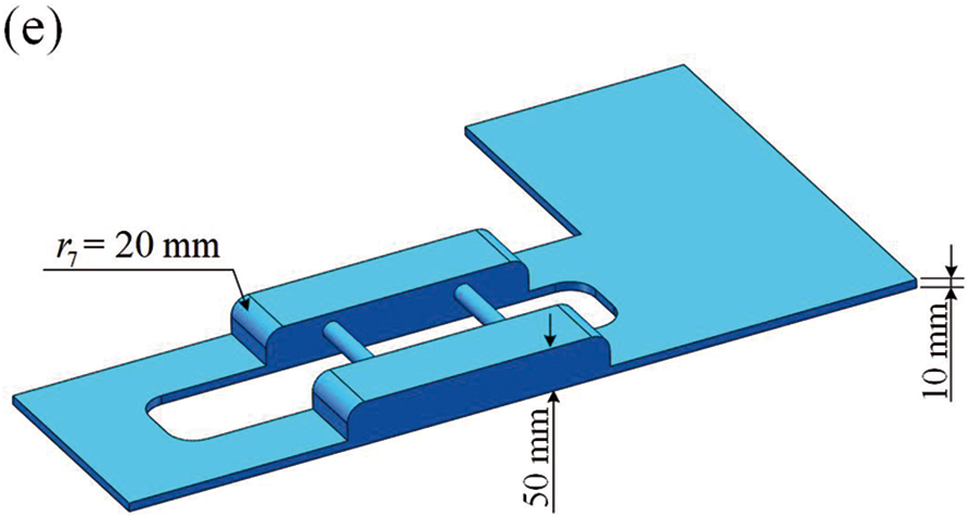
Figure 10: A soft crawling robot for crawling in different road locomotion. (a) Three-segments FRSPA structure and rigid fixture. (b) A soft crawling actuator consisting of eight identical FRSPAs. (c) Flat road. Irregular road surface with obstructions: (d) vertical view; (e) oblique view
The soft crawling robot is composed of multi-segment FRSPAs, and the control of each segment and each air chamber is independent of each other. In order to realize crawling along the length direction on the flat road shown in Fig. 10e, it is necessary to set a suitable crawling gait. Fig. 11 shows the time variation of pressure applied by each air chamber in the crawling process of the soft crawling robot. According to the air chamber position diagram in Fig. 1c and Fig. 10b, there are a total of 8 × 3 × 4 = 96 air chambers in eight three-segment FRSPAs. 1 to 96 are defined in sequence, representing the number of each air chamber. For example, Label-22 and 91 stand for FRSPA-B-
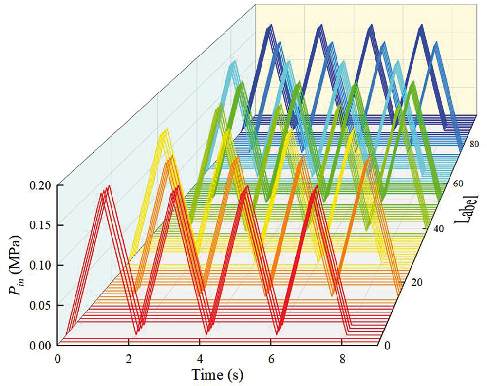
Figure 11: Minimum input of
The distance between the soft crawling robot and the starting point on the flat road and the boundary is 45 mm, and the total length of the rigid support is 210 mm. At the same time, according to Eqs. (9)–(11), in order to improve the crawling efficiency, that is, to complete the whole process with the least number of steps, and ensure the stability of the whole crawling process, the contact with the previous FRSPA is not allowed. Therefore, in the process of each creeping step, the input pressure of part-
Fig. 12 shows the crawling process of the actuator on a flat road. And its sub processes are: (a) Positional relationship. (b) Crawling sequence: (1) 0–1 s, the chamber FRSPA-ACF-
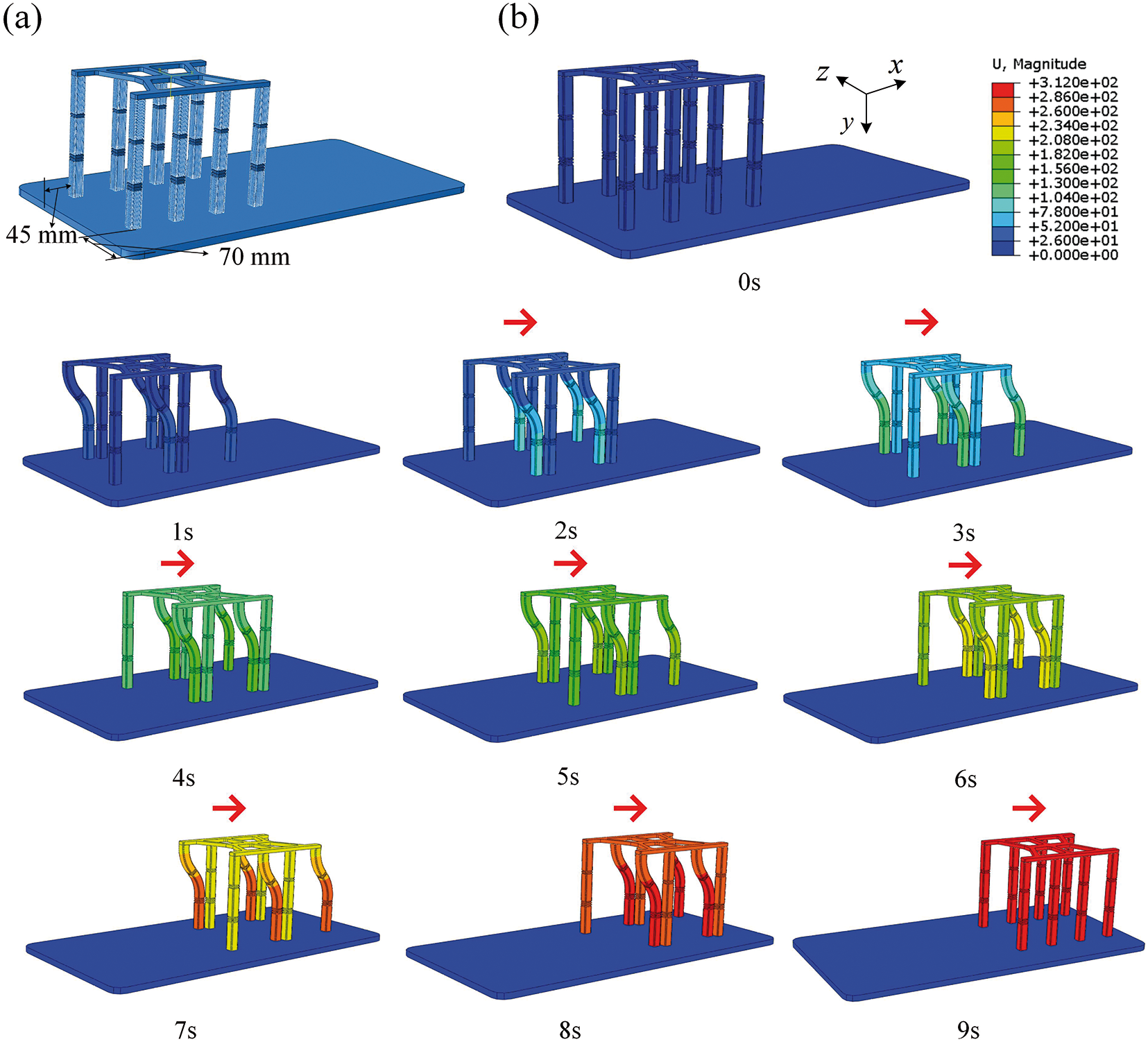
Figure 12: Numerical investigation of the process of crawling on a flat road for soft crawling robot. (Unit: mm)
A specific load is applied at the specified position to control the step size, thus completing the crawling simulation of the specified distance. Table 2 shows the forward distance of each moving step during the crawling process. The actuator crawls 312 mm along the x direction to reach the end position.

5.2 Crawling on the Road with Obstacles
In the process of horizontal crawling in Section 5.1, only part-
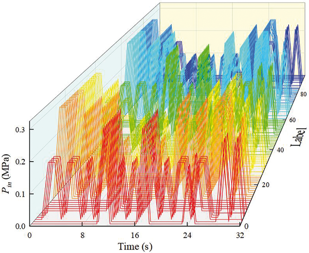
Figure 13: Minimum input of
The simulation process of a soft crawling robot crawling on the road with obstacles is shown in Fig. 14. Fig. 14 shows the steps of the climbing process in detail. Combined with the specific structural sizes of Figs. 10d and 10e, and calculated by Eqs. (9) and (10), the minimum pressure required by axial elongation and bending motion of FRSPA can be obtained. During the 0–3 s in Fig. 14b, since the step is 40 mm higher than the ground of the soft crawling robot, it is necessary to use the FRSPA-BCFG to inflate each air chamber 0.3 MPa and raise the actuator 50 mm overall (Table 3). Then, the FRSPA-BCFG is deflated, and the first two lower limbs of the soft crawling robot along the crawling direction can be placed on the step. Similarly, according to the position and space relationship, constantly adjust the size of the pressure and the position applied, and gradually realize the locomotion of the center of gravity to the direction of the step. When t = 12 s, it means that FRSPA-BCDEGH is all on the step, and the center of gravity is already above the step, so it only needs to follow the horizontal gait in Section 5.1. Since the lower step and the upper step belong to symmetrical motion, it is not shown in detail. After crossing the obstacle, the actuator finally crawls along the z positive direction. The distance between the two actuators along the z direction is lAE = 130 mm. In order to improve the locomotion speed, the load size was set at 0.25 MPa and the displacement was 65 mm. After four gaits, the final position was reached. Table 3 shows the displacement of each time node.
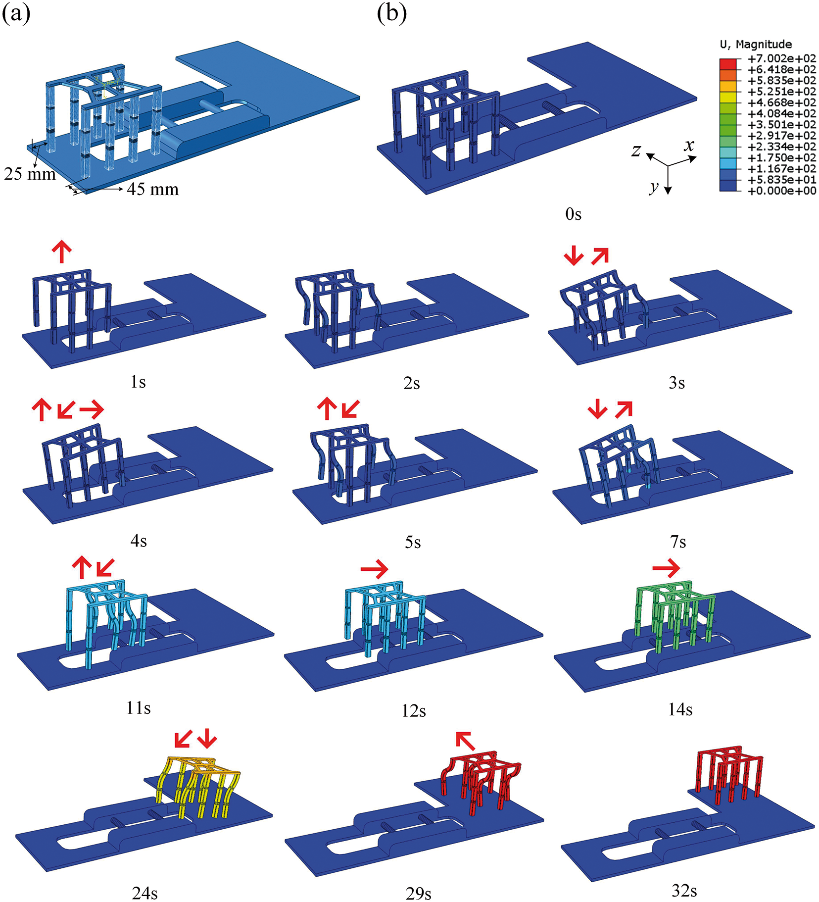
Figure 14: Numerical investigation of the process of crawling on the road with obstacles for soft crawling robot. (Unit: mm) (a) Positional relationship. (b) Crawling sequence: (1) 0–1 s, chamber-BCFG inflated, overall rise; (2) 1–2 s, chamber-ADEH bending; (3) 2–3 s, chamber- BCFG let off air and start to climb the obstacle; (4) 3–4 s, chamber-ADEH vent, the first two actuators up the obstacle; (5) 4–14 s, repeat the above locomotion to make the actuator crawl each FRSPA of the actuator up the steps successively; (6) 14–24 s, down the obstacle; (7) 24–29 s, complete the descending step and crawl along the z direction; (8) 29–32 s, complete the required distance in the z direction, release all pressure, and reach the final position

Section 5.1 mainly shows the locomotion of the actuator along the length of the rigid support without side bending and elongation. On the basis of Section 5.1, Fig. 14 further discusses the axial production of the actuator and the coordinated locomotion of the side bending so as to complete more complex crawling locomotion and be more realistic.
Sections 5.1 and 5.2 introduce the eight-legged crawling robot composed of 3D-FRSPA with a three-segment structure and simulate the numerical simulation research of crawling and obstacle avoidance on flat road and L-shaped road with steps, respectively. As can be seen from Fig. 10b, the FRSPA of each segment can independently and freely bend and extend along the axial direction. Compared with the unidirectional bending actuator [9], the performance is more flexible. Compared with the aforementioned work [39], the difficulty of modeling is simplified, and the two-sided winding fibers limit the radial deformation and improve the bending performance. And compared with [9,33], a soft crawling robot has multiple crawling directions, which is more suitable for complex road conditions and practical application (Fig. 14). The actuator with segmental bending control has better flexibility and further improved obstacle avoidance compared to [14,19]. Therefore, to sum up, the soft crawling robot composed of 3D-FRSPA proposed in this paper is a deep expansion of mobile robots, especially in the complex nonlinear obstacle avoiding crawling, with better motion mechanism and application advantages.
Inspired by the multi-segment structure of crab claw and human finger, we propose a novel multi-segment 3D-FRSPA with four symmetrical cylindrical air chambers inside which each segment can independently bend in omni-directional. The double-wound fiber structure further improves the bending performance of the actuator. Based on this, an eight-leg crawling robot is designed, which is used for crawling in different road conditions.
The theoretical models of statics kinematics of single and multi-segments 3D-FRSPA are derived, and its mechanical behavior is discussed in depth. It provides good theoretical guidance for the design of the motion mechanism of crawling locomotion. Detailed parameter analysis is carried out for single and multi-segment FRSPA, involving fibers, length of air chamber and segment, and radius of circular air chamber. The effects of different parameters on the bending properties of FRSPA are also given. It provides the best design scheme for the soft mobile robot.
The finite element numerical simulation results of the crawling locomotion on the flat road and the L-shaped road with obstacles are given, respectively. By matching the appropriate motion mechanism and combining the results of the mechanical model, the soft mobile robot can complete the corresponding crawling under different environmental conditions.
In conclusion, this work makes up for the shortcomings of existing SPAs. It introduces a novel structure of 3D-FRSPA, which further improves actuators’ bending performance and expands the soft crawling robot’s application range. Furthermore, future research work will design targeted prototype experiments according to parameter analysis conclusions and numerical simulation results. While ensuring flexibility, the multi-segment FRSPA designed in this paper has a larger number of air chambers and applies more different air values. The structure will be optimized and designed in the future. Based on theoretical verification, the results will be further verified through experiments to improve the practical application range and fully explore the deep application value of the pipe in curved edge pipeline detection and complex terrain detection.
Acknowledgement: This work is supported by the Fundamental Research Funds for the Central Universities and the Postgraduate Research & Practice Innovation Program of Jiangsu Province, China. The financial supports are gratefully acknowledged.
Funding Statement: This work is supported by the Fundamental Research Funds for the Central Universities (Grant No. B230205021) and the Postgraduate Research & Practice Innovation Program of Jiangsu Province, China (Grant No. KYCX22_0592). The financial supports are gratefully acknowledged.
Author Contributions: The authors confirm contribution to the paper as follows: study conception and design: Bingzhu Wang; data collection: Bingzhu Wang, Xiangrui Ye; analysis and interpretation of results: Xiangrui Ye; draft manuscript preparation: Bingzhu Wang. All authors reviewed the results and approved the final version of the manuscript.
Availability of Data and Materials: Data and materials will be made available on request.
Conflicts of Interest: The authors declare that they have no conflicts of interest to report regarding the present study.
References
1. Hou, X., Zhang, L., Su, Y., Gao, G., Liu, Y. et al. (2023). A space crawling robotic bio-paw (SCRBP) enabled by triboelectric sensors for surface identification. Nano Energy, 105, 108013. [Google Scholar]
2. Sharma, R., Gaur, P., Bhatt, S., Joshi, D. (2021). Optimal fuzzy logic-based control strategy for lower limb rehabilitation exoskeleton. Applied Soft Computing, 105, 107226. [Google Scholar]
3. Kucuk, S. (2017). Optimal trajectory generation algorithm for serial and parallel manipulators. Robotics and Computer-Integrated Manufacturing, 48, 219–232. [Google Scholar]
4. Shao, W., Zhang, H., Wu, Y., Sheng, N. (2021). Application of fusion 2D lidar and binocular vision in robot locating obstacles. Journal of Intelligent & Fuzzy Systems, 41(3), 4387–4394. [Google Scholar]
5. Wang, X., Li, X., Wang, J., Fang, X., Zhu, X. (2016). Data-driven model-free adaptive sliding mode control for the multi degree-of-freedom robotic exoskeleton. Information Sciences, 327, 246–257. [Google Scholar]
6. Fuentes-Alvarez, R., Hernandez, J. H., Matehuala-Moran, I., Alfaro-Ponce, M., Lopez-Gutierrez, R. et al. (2022). Assistive robotic exoskeleton using recurrent neural networks for decision taking for the robust trajectory tracking. Expert Systems with Applications, 193, 116482. [Google Scholar]
7. Liu, B., Feng, J., Yu, K., Li, J., Hu, Q. et al. (2022). Three-dimensional auxetic structure design methods based on bulking-induced deformation and the application in soft crawling robot. Composites Part B: Engineering, 244, 110146. [Google Scholar]
8. Chen, Y., Hu, B., Zou, J., Zhang, W., Wang, D. et al. (2020). Design and fabrication of a multi-motion mode soft crawling robot. Journal of Bionic Engineering, 17, 932–943. [Google Scholar]
9. Rehman, T., Faudzi, A. A. M., Dewi, D. E. O., Ali, M. S. M. (2017). Design, characterization, and manufacturing of circular bellows pneumatic soft actuator. The International Journal of Advanced Manufacturing Technology, 93(9), 4295–4304. [Google Scholar]
10. Yang, Y., He, Z., Lin, G., Wang, H., Jiao, P. (2022). Large deformation mechanics of the thrust performances generated by combustion-enabled soft actuators. International Journal of Mechanical Sciences, 229, 107513. [Google Scholar]
11. Rodrigue, H., Wang, W., Kim, D. R., Ahn, S. H. (2017). Curved shape memory alloy-based soft actuators and application to soft gripper. Composite Structures, 176, 398–406. [Google Scholar]
12. Baydere, B. A., Talas, S. K., Samur, E. (2018). A novel highly-extensible 2-DOF pneumatic actuator for soft robotic applications. Sensors and Actuators A: Physical, 281, 84–94. [Google Scholar]
13. Yoon, Y., Park, H., Lee, J., Choi, J., Jung, Y. et al. (2023). Bioinspired untethered soft robot with pumpless phase change soft actuators by bidirectional thermoelectrics. Chemical Engineering Journal, 451, 138794. [Google Scholar]
14. Wang, J., Min, J., Fei, Y., Pang, W. (2019). Study on nonlinear crawling locomotion of modular differential drive soft robot. Nonlinear Dynamics, 97, 1107–1123. [Google Scholar]
15. Zhang, Z., Wang, X., Wang, S., Meng, D., Liang, A. (2019). Design and modeling of a parallel-pipe-crawling pneumatic soft robot. IEEE Access, 7, 134301–134317. [Google Scholar]
16. Jin, Q., Sun, Y., Geng, J., Yuan, X., Chen, T. et al. (2021). Bioinspired soft caterpillar robot with ultra-stretchable bionic sensors based on functional liquid metal. Nano Energy, 84, 105896. [Google Scholar]
17. Song, C. W., Lee, D. J., Lee, S. Y. (2016). Bioinspired segment robot with earthworm-like plane locomotion. Journal of Bionic Engineering, 13(2), 292–302. [Google Scholar]
18. Sun, K., Tian, Y. (2022). Numerical investigation of a bioinspired multi-segment soft pneumatic actuator for grasping applications. Materials Today Communications, 31, 103449. [Google Scholar]
19. Yeh, C. Y., Chen, C. Y., Juang, J. Y. (2022). Soft hopping and crawling robot for in-pipe traveling. Extreme Mechanics Letters, 39, 100854. [Google Scholar]
20. Mosadegh, B., Polygerinos, P., Keplinger, C., Wennstedt, S., Shepherd, R. F. et al. (2014). Pneumatic networks for soft robotics that actuate rapidly. Advanced Functional Materials, 4(15), 2163–2170. [Google Scholar]
21. Scharff, R. B. N., Fang, G. X., Tian, Y. J., Wu, J., Geraedts, J. M. P. et al. (2021). Sensing and reconstruction of 3-D deformation on pneumatic soft robots. IEEE/ASME Transactions on Mechatronics, 26(4), 1877–1885. [Google Scholar]
22. Onal, C. D., Rus, D. (2013). Autonomous undulatory serpentine locomotion utilizing body dynamics of a fluidic soft robot. Bioinspiration & Biomimetics, 8(2), 026003. [Google Scholar]
23. Rafsanjani, A., Zhang, Y., Liu, B., Rubinstein, S. M., Bertoldi, K. (2018). Kirigami skins make a simple soft actuator crawl. Science Robotics, 3(15), eaar7555. [Google Scholar] [PubMed]
24. Must, I., Sinibaldi, E., Mazzolai, B. (2019). A variable-stiffness tendril-like soft robot based on reversible osmotic actuation. Nature Communications, 10(1), 1–8. [Google Scholar]
25. Zhang, Y., Yang, D., Yan, P., Zhou, P., Zou, J. et al. (2022). Inchworm inspired multimodal soft robots with crawling, climbing, and transitioning locomotion. IEEE Transactions on Robotics, 38(3), 1806–1819. [Google Scholar]
26. Jeong, H., Wang, W. (2023). Self-adaptive detachable pneumatic soft actuators using uniformly distributed temporary-bonding-fasteners for wearable applications. Sensors and Actuators A: Physical, 349, 114083. [Google Scholar]
27. Singh, G., Xiao, C., Hsiao-Wecksler, E. T., Krishnan, G. (2018). Design and analysis of coiled fiber reinforced soft pneumatic actuator. Bioinspiration & Biomimetics, 13(3), 036010. [Google Scholar]
28. Wirekoh, J., Parody, N., Riviere, C. N., Park, Y. L. (2020). Design of fiber-reinforced soft bending pneumatic artificial muscles for wearable tremor suppression devices. Smart Materials and Structures, 30(1), 015013. [Google Scholar]
29. Rakhtala, S. M., Ghayebi, R. (2022). Real time control and fabrication of a soft robotic glove by two parallel sensors with MBD approach. Medical Engineering and Physics, 100, 103743. [Google Scholar] [PubMed]
30. Verma, M. S., Ainla, A., Yang, D., Harburg, D., Whitesides, G. M. (2018). A soft tube-climbing robot. Soft Robotics, 5(2), 133–137. [Google Scholar] [PubMed]
31. Shepherd, R. F., Ilievski, F., Choi, W., Morin, S. A., Stokes, A. A. et al. (2011). Multigait soft robot. Proceedings of the National Academy of Sciences of the United States of America, 108(51), 20400–20403. [Google Scholar] [PubMed]
32. Tolley, M. T., Shepherd, R. F., Mosadegh, B., Galloway, K. C., Wehner, M. et al. (2014). A resilient, untethered soft robot. Soft Robotics, 1(3), 213–223. [Google Scholar]
33. Fei, Y., Wang, X. (2015). Study on nonlinear obstacle avoidance on modular soft robots. Nonlinear Dynamics, 82(1–2), 891–898. [Google Scholar]
34. Wang, B., Yu, T. (2023). Numerical investigation of novel 3D-SPA for gripping analysis in multi-environment. International Journal of Mechanical Sciences, 240, 107916. [Google Scholar]
35. Zhang, Y., Xu, D., Zhang, Z., Ding, S., Wu, W. et al. (2021). Mechanical properties and clamping behaviors of snow crab claw. Journal of the Mechanical Behavior of Biomedical Materials, 124, 104818. [Google Scholar] [PubMed]
36. Ovur, S., Zhou, X., Qi, W., Zhang, L., Hu, Y. et al. (2021). A novel autonomous learning framework to enhance sEMG-based hand gesture recognition using depth information. Biomedical Signal Processing and Control, 66, 102444. [Google Scholar]
37. Marechal, L., Balland, P., Lindenroth, L., Petrou, F., Kontovounisios, C. et al. (2021). Toward a common framework and database of materials for soft robotics. Soft Robotics, 8(3), 284–297. [Google Scholar] [PubMed]
38. Polygerinos, P., Wang, Z., Overvelde, J. T. B., Galloway, K. C., Wood, R. J. et al. (2015). Modeling of soft fiber-reinforced bending actuators. IEEE Transactions on Robotics, 31(3), 778–789. [Google Scholar]
39. Tian, Y., Zhang, Q., Cai, D., Chen, C., Zhang, J. et al. (2022). Theoretical modelling of soft robotic gripper with bioinspired fibrillar adhesives. Mechanics of Advanced Materials and Structures, 29(15), 2250–2266. [Google Scholar]
40. Connolly, F., Walsh, C. J., Bertoldi, K. (2017). Automatic design of fiber-reinforced soft actuators for trajectory matching. Proceedings of the National Academy of Sciences of the United States of America, 114(1), 51–56. [Google Scholar] [PubMed]
41. Zhong, G., Dou, W., Zhang, X., Yi, H. (2021). Bending analysis and contact force modeling of soft pneumatic actuators with pleated structures. International Journal of Mechanical Sciences, 193, 106150. [Google Scholar]
Cite This Article
 Copyright © 2024 The Author(s). Published by Tech Science Press.
This work is licensed under a Creative Commons Attribution 4.0 International License , which permits unrestricted use, distribution, and reproduction in any medium, provided the original work is properly cited.
 Downloads
 Citation Tools