
 Submit a Paper
 Propose a Special lssue
 Open Access
ARTICLE

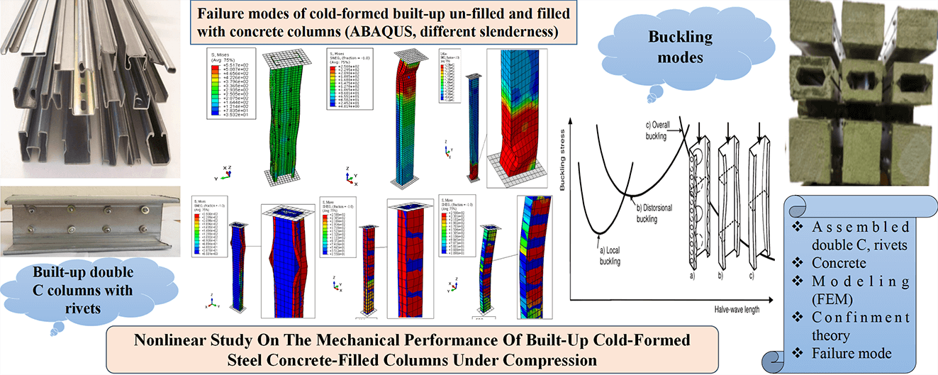
Nonlinear Study on the Mechanical Performance of Built-Up Cold-Formed Steel Concrete-Filled Columns under Compression
1 Civil Engineering Laboratory, Faculty of Technology, Department of Civil Engineering, Badji Mokhtar-Annaba University, P. O. Box 12, Annaba, 23000, Algeria
2 Department of Civil Engineering, Faculty of Engineering and Technology, Jamia Millia Islamia (A Central University), New Delhi, 110025, India
3 Civil Engineering Department, University of Garmian, Kalar, 46021, Iraq
4 Department of Civil Engineering, Harran University, Sanliurfa, 63510, Turkey
5 Structural Engineering and Construction Management Department, Future University in Egypt, New Cairo, 11835, Egypt
6 Department of Civil Engineering, Covenant University, Ota, 112233, Nigeria
* Corresponding Authors: Oulfa Harrat. Email: ; S. M. Anas. Email:
(This article belongs to the Special Issue: Recent Advances in Computational Methods for Performance Assessment of Engineering Structures and Materials against Dynamic Loadings)
Computer Modeling in Engineering & Sciences 2024, 139(3), 3435-3465. https://doi.org/10.32604/cmes.2023.044950
Received 12 August 2023; Accepted 07 November 2023; Issue published 11 March 2024
 View Full Text
 Download PDF
Abstract
Given their numerous functional and architectural benefits, such as improved bearing capacity and increased resistance to elastic instability modes, cold-formed steel (CFS) built-up sections have become increasingly developed and used in recent years, particularly in the construction industry. This paper presents an analytical and numerical study of assembled CFS two single channel-shaped columns with different slenderness and configurations (back-to-back, face-to-face, and box). These columns were joined by double-row rivets for the back-to-back and box configurations, whereas they were welded together for the face-to-face design. The built-up columns were filled with ordinary concrete of good strength. Finite element models were applied, using ABAQUS software, to assess mechanical performance and study the influence of assembly techniques on the behavior of cold-formed columns under axial compression. Analytical approaches based on Eurocode 3 and Eurocode 4 recommendations for un-filled and concrete-filled columns respectively were followed for the numerical analysis, and concrete confinement effects were also considered per American Concrete Institute (ACI) standards for face-to-face and box configurations. The obtained results indicated a good correlation between the numerical results and the proposed analytical methodology which did not exceed 8%. The failure modes showed that the columns failed due to instabilities such as local and global buckling.Graphic Abstract
Keywords
Nomenclature
| CF-CFS | Concrete-filled cold-formed steel |
| CFS | Cold-formed steel |
| CFST | Concrete-filled steel tube |
| B | Width of the cross-section |
| bp | Width of the profile |
| H | Height of the cross-section |
| C | Length of dropped edge |
| R | Bend radius |
| t | Thickness of the cross-section |
| B’ | Width of the concrete |
| H’ | Height of the concrete |
| Es | Young’s modulus of steel |
| νs | Poisson’s ratio of steel |
| fc | Compressive strength of unconfined concrete |
| Ɛc | Compressive strain of unconfined concrete |
| fl | The confining pressure of the concrete |
| k1, and k2 | Constants, which were set as 4.1 and 20.5, respectively |
| Ecc | Modulus of elasticity of concrete |
| νc | Poisson’s ratio of concrete |
| fcc | Compressive strength of confined concrete |
| Ɛcc | Compressive strain of confined concrete |
| k3 | Material degradation parameter |
| Aeff | Effective cross-sectional area |
| Nc.Rd | Compressive strength |
| Reduced slenderness | |
| βA | Coefficient of reduction of the section |
| NPl,Rd | The plastic resistance |
| Ac | Cross section of concrete |
| As | Cross-section of steel |
| γM1, γc | Partial material safety factor of steel 1.1 and concrete 1.5, respectively |
| Ncr | The elastic critical normal force for the relevant buckling mode, calculated with the effective flexural stiffness (EI)e |
| (EI)e | The flexural rigidity of the composite column relative to the buckling plane considered |
| lf | Buckling length of the column |
| Ecm | The secant modulus of elasticity of the concrete |
| γc | The safety coefficient for stiffness which was equal to 1.35 |
| NPl,R | The value of the plastic resisting normal force NPl,Rd calculated by setting all partial safety factors γM1, γc equal to 1 (i.e., using the characteristic strengths of the materials) |
| γ | Density |
| fy | Yield strength of steel |
| fu | Tensile strength of steel |
| Ɛy | Yield strain of steel |
| Ɛu | Ultimate strain of steel |
| fctm | Average tensile strength |
| fctk 0.05, fctk 0.95 | Characteristic tensile strengths of concrete |
| χd | The reduction coefficient |
In recent years, the utilization of cold-formed steel (CFS) components in the construction industry has surged, primarily due to advancements in manufacturing technology, which encompass superior-quality steel, intricate section designs, and enhanced forming techniques [1,2]. These developments have not only enhanced the competitiveness of this structural solution but have also resulted in a growing market share on a global scale [3,4]. Cold-formed steel materials are commonly shaped into a variety of sections, such as Z-sections, C-channel sections, hat sections, and other specialized profiles [5,6]. Typically, these shapes are achieved by cold-forming steel sheets through either bending or rolling processes to attain the desired configurations [7–10]. Thin-walled CFS sections, in particular, are increasingly establishing a presence in the steel construction industry owing to their lightweight nature, rapid and straightforward assembly, precision in dimensionality, and wide range of achievable shapes [11–14]. However, it is important to note that these thin-walled elements, especially those featuring open cross-sections, are highly susceptible to structural instabilities like local and distortional buckling. Consequently, to support significant loads, the use of assembled elements becomes indispensable [15].
In the construction industry, the significance of CFS built-up elements has grown substantially in recent times driven by their numerous advantages, including enhanced strength and rigidity, underpinning their employment when hot-rolled or CFS individual sections cannot support the applied loads [16–18]. Assembled sections generally consist of two or more sections connected either back-to-back to create open sections or face-to-face to produce closed sections [19,20]. It is noteworthy that the axial compressive capacity of built-up elements is typically twice as robust as that of their constituent parts. Furthermore, closed sections exhibit superior torsional rigidity compared with open sections [21].
Cold-formed profiles come with certain drawbacks, notably their elevated slenderness (width/thickness ratio), which can lead to instability modes within the cross-section, including local, distortional, and global buckling [22,23]. When these profiles are subjected to forces applied in their plane, part of the cross-section in compression may buckle long before reaching its elastic limit, although, the presence of this buckling is not automatically accompanied by the ruin of the member. Through buckling, the cross-section of a member is deformed, and this deformation causes rotations without any translation (pure rotation) [22,24]. Furthermore, global buckling is characterized by a translation as a rigid body (translation and/or rotation without undergoing deformations) without an invariability of the cross-section at the level of the flanges and the web. In contrast, buckling by deformation affects part of the corners and stiffeners, leading to lateral displacement [25,26].
Concrete-filled steel tube (CFST) columns find frequent application in civil construction as a reliable solution to address buckling issues, owing to their geometrical qualities, outstanding compression and fire performance, excellent strength, and ductility compared with reinforced concrete or ordinary steel sections [27–30]. The appropriate combination between steel and concrete, especially in the case of tubular columns, offers a commendable concrete confinement effect, particularly when contrasted with square columns, due to the favorably low width/thickness ratio [31]. While the confinement effect of the steel tube on the concrete core improves the concrete’s resilience, the concrete core in the steel tube mitigates or retards the onset of local buckling in the steel tube [32]. Various researchers found that the confinement effect between the outer steel tube and the concrete fill is a key factor for CFST columns, which implied that the concrete inside these tubes required no additional formwork or reinforcement, as its outer surface is shielded from any exterior influences [33,34]. Also, local buckling of the steel tube is postponed, since it can only occur within the concrete, which itself can only deform on the outside [35].
Recently, the development of concrete-filled cold-formed steel (CF-CFS) built-up columns offers the flexibility of combining in diverse geometric configurations, as this pairing of steel and concrete not only augments the load-bearing capacity of the structural element under compression but also elevates the structure’s fire resistance and safety. Consequently, these composite solutions have the potential to overcome instability problems, further exploit the mechanical properties, and promote the utilization of high-strength steel [36]. Rahnavard et al. [37–40] investigated the performance of cold-formed steel built-up columns filled with concrete under various parameters, encompassing compression, fire resistance, and equivalent temperature. Their obtained results showed a good accuracy between the experimental results and the proposed methodology. Craveiro et al. [41] investigated the factors influencing the fire performance of concrete-filled built-up cold-formed steel columns including dimensions, properties, and geometry. The findings demonstrated that the combination of steel and concrete components provided improved fire resistance, delaying structural failure, and ensuring the columns’ integrity during fire events. Chen et al. [42] investigated how axial compression loads affect the structural behaviour of built-up cold-formed steel section stub columns filled with concrete. To assess the columns’ load capacity, deformation, and failure modes, experimental tests were carried out. Additionally, the behaviour of the column was examined by considering some factors, such as column dimensions, steel thickness, and concrete grades. In the research by Teoh et al. [43], the cold-formed concrete-filled box columns were put through experimental tests to determine their deformation characteristics, load-carrying capacity, and failure modes. The findings shed important light on these columns’ structural reaction and failure mechanisms, as well as on how to improve their design and use them in building projects. In addition, Senthilkumar et al. [44] studied the effect of longitudinal stiffeners under compression on the cold-formed steel square columns filled with concrete for various slenderness values, both numerically and experimentally. It demonstrated that there was a positive impact of the stiffeners within the slenderness range, attributed to a reduction in the buckling factor.
According to the literature, EN 1994-1-1 [45] addresses fundamental concepts and related design methods of hot-formed composite columns (steel-concrete). However, there is a notable absence of research regarding the behavior of cold-formed steel columns filled with concrete. To strengthen the understanding of this category, a very powerful numerical model has been developed that takes into consideration the fabrication process of cold-formed elements and aims to identify the most efficient design to reduce column instability.
When a slender member with a small thickness is subjected to axial compressive loading, it may locally buckle at certain points along its length where the stresses are highest. Therefore, it is necessary to analyze factors contributing to local buckling, such as the applied loads, and boundary conditions. All recent studies neglected to consider the influence of the assembly method on the behavior of cold-formed steel built-up columns filled with concrete. The behavior of rivets was replaced by interactions, which do not reflect the reality in practice. This paper presents a nonlinear numerical and analytical study of double-C columns constructed from cold-formed steel in different configurations (back-to-back, face-to-face, and box) of various lengths (600, 1200, 1800, and 2000 mm). The addition of concrete in these built-up columns could significantly enhance the mechanical performance of CFS sections and reduce instability-induced deformations. The nonlinear numerical simulation was based on the finite element method and was performed using ABAQUS software. To validate the numerical results, an analytical approach based on the specifications of EN 1993-1-3 [46] and EN 1994-1-1 [45] was employed, along with the use of ACI [47] to integrate the confinement theory. Additionally, the paper examines the effects of local buckling on stress distribution and lateral strains in the assembled columns, highlighting the redistribution of stresses following buckling.
The main objective of civil engineering is to create more economical and resistant elements. This is achieved through research into new profile shapes, calculation methods, and assembly techniques. As a result, modern techniques are converging toward composite sections. This study was devoted to determining the mechanical strength of cold-formed composite columns, both un-filled and filled with concrete. Each column was comprised of two cold-formed steel C-profiles with different configurations. These composite columns were then filled with ordinary, non-reinforced concrete, which had a density of approximately 2400 kg/m3.
Several types of research have confirmed that the un-filled cold-formed steel built-up column filled with concrete is a better solution that can be used. The analytical part of this investigation was based on Eurocode 3 Part 1-3 [46], which covers the construction of cold-formed steel buildings and civil engineering structures. Eurocode 4 Part 1-1 [45] covers the design methods for composite elements (steel-concrete).
2.1 Geometry Details of the CFS Built-Up Columns
Our research focused on studying the behavior of cold-formed built-up columns through the effect of slenderness (Fig. 1). Three positions of assembled cold-formed columns were investigated: the first was a back-to-back configuration (Fig. 2a), where the two C-sections were connected at the web using double row flat-head rivets with a transverse pitch of 35 mm. However, the longitudinal pitch between the rivets was 50 mm as shown in Fig. 2d. The second configuration involved a face-to-face arrangement with connections made through ordinary welding (Fig. 2b). The rivets used were 6 mm in diameter and of nuance S235, with a tensile strength at rupture of 400 MPa. In the box configuration, the rivets were placed in the upper and lower flanges at 50 mm spacing in a single row (Fig. 2c), and the use of this configuration offered many advantages such as stiffening the flanges of the assembled element and eliminating the need for concrete formwork during pouring.

Figure 1: Three-dimensional geometry of CFS built-up un-filled profiles: (a) Back-to-back; (b) face-to-face; (c) box

Figure 2: Cross-section of assembled CFS un-filled models: (a) Back-to-back; (b) face-to-face; (c) box; (d) longitudinal view of the back-to-back model
The three models shown in Fig. 1 were filled with concrete of strength class C25/30, as depicted in Fig. 3. The cross-sectional geometry of the un-filled and concrete-filled columns is shown in Figs. 2 and 4, respectively. The dimensions were chosen following the rules and limitations of Eurocode 3 Part 1-3 [46]. Therefore, we studied cold-formed double-C columns of different lengths (600, 1200, 1800, and 2000 mm) with a thickness of 1.2 mm. The steel quality was CR250, classified as Class 4. All geometrical properties of the un-filled and concrete-filled models are presented in Table 1.

Figure 3: Three-dimensional geometry of CFS built-up profiles filled with concrete: (a) Back-to-back partially encased with concrete; (b) face-to-face filled with concrete; (c) box filled with concrete
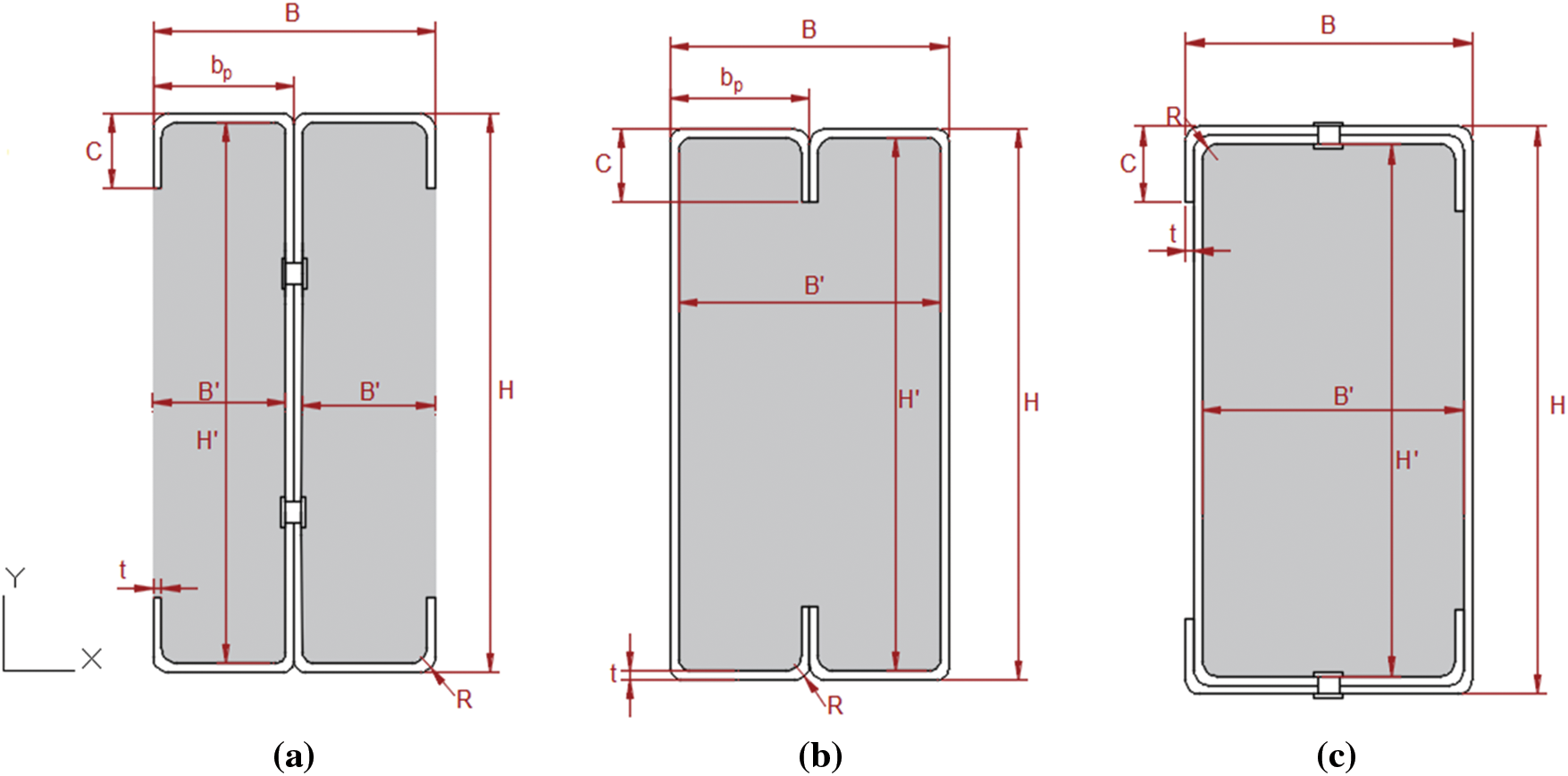
Figure 4: Cross-sectional geometry of C-section models filled with concrete: (a) Back-to-back partially encased with concrete; (b) face-to-face filled with concrete; (c) box filled with concrete

The behavior of concrete-filled columns presented in Fig. 5 was based on the theories of confined concrete, which were abstracted from the ACI (American Concrete Institute) Committee 318 (1999) [47]. From the stress-strain relationship curves, the compressive strength ƒc of unconfined concrete and its corresponding strain Ɛc, which equals 0.003 according to the ACI, were smaller than those of confined concrete (fcc and Ɛcc). This indicated the use of confinement parameters.
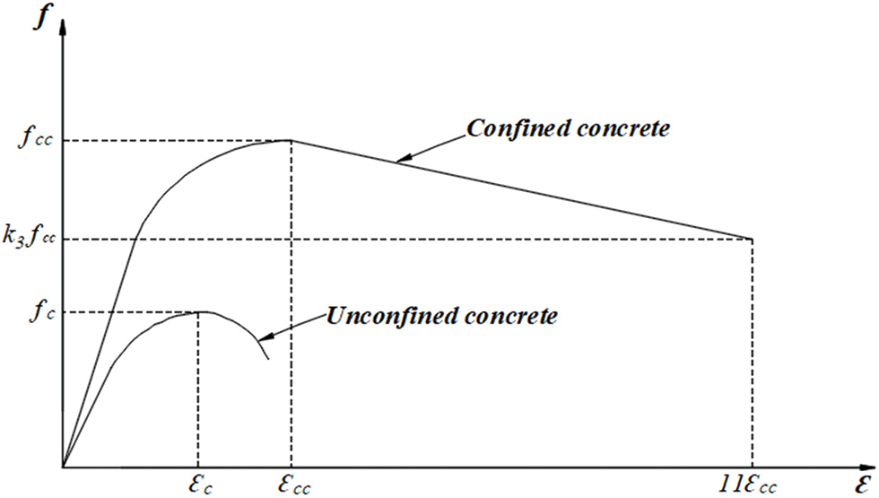
Figure 5: Stress-strain relationship of unconfined and confined concrete
As derived from Mander et al. [48], the termination of the compressive plastic strain and strength of confined concrete is suggested in Eqs. (1) and (2):
wherek1 and k2 are constants based on the study by Richart et al. [49] and which were set as 4.1 and 20.5, respectively; Ɛc and fc are the compressive strain and strength of unconfined concrete, respectively; Ɛcc and fcc are the compressive strain and strength of confined concrete, respectively; fl is the confining pressure of the concrete.
The B/t ratio significantly influences the behavior of concrete-filled columns, especially in minimizing local instabilities. When the B/t ratio is high, reinforced columns are more likely to experience local buckling compared with those with a low B/t ratio [31]:
where B is the width of the cross-section; t is the thickness of the cross-section; fy is the yield strength of steel.
For concrete-filled rectangular sections, the material degradation parameter, k3, is given by [31]:
The studied sections were classified as Class 4, influenced by the ability of the cross-sections to plasticize, wherein local buckling limits the compressive strength for axially loaded elements. The determination of the effective cross-section properties was based on the effective width method detailed in Eurocode 3 Part 1-3 [46].
The determination of the effective cross-section was based on the effective width method according to EN 1993-1-3 [46] and the study by Ye et al. [24]. In the effective width approach, rather than considering the non-uniform distribution of stress across the width of the element, it is assumed that the entire load is supported by an effective width be, which is subjected to uniformly distributed stress equal to the stress at the edge of the plate [50,51], as illustrated in Fig. 6.
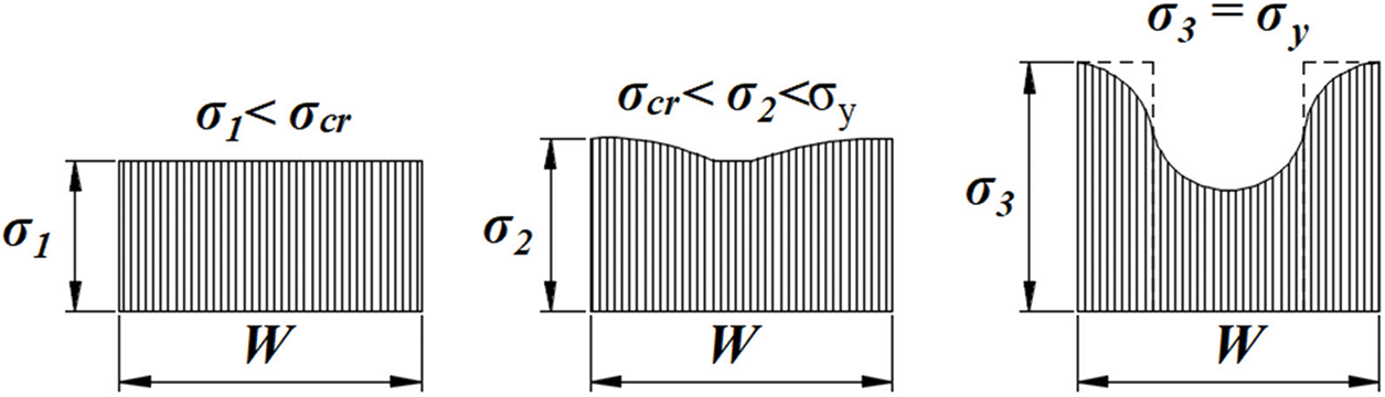
Figure 6: Evolution of the stress distribution during the loading of a stiffened element
The calculation of the post-critical force of a stiffened planar element was thus simplified to determine the effective width. Also, strength reductions due to local buckling effects were considered. For the C-section, the effective width was determined for each compression part and then the ultimate load of the section could be obtained by assuming that the load was taken up only by the effective sectors. The effective cross-section for a C-section was determined by the following equation:
where χd is the reduction coefficient.
The design process was based mainly on determining the critical elastic loads for these failure modes. The effective cross-sections of the models studied were of Class 4 and under compression as presented in Fig. 7.
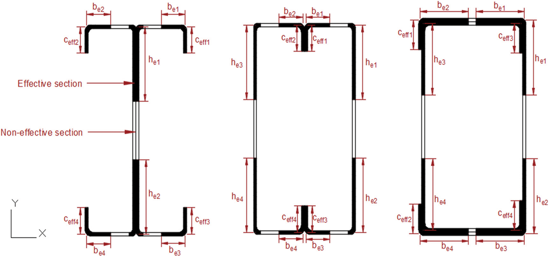
Figure 7: The effective cross-sections of the studied columns
2.4 Buckling Resistance according to Eurocode 3 and Eurocode 4
For the Class 4 un-filled built-up short columns, local buckling in one or more cross-sections prevents the attainment of the plastic flow load, limiting the design compressive strength to the local buckling resistance. The compressive strength is given by:
where Aeff is the effective cross-sectional area, and Nc.Rd is the compressive strength.
For compressed slender columns, resistance verification according to Eurocode 3 [46] was based on the buckling lengths for each of the two main axes, depending on the connections at their ends. Furthermore, the minimum moment of inertia required to withstand the critical Euler loads was used to pre-dimension the element. The verification formula given in Eq. (9) was then applied, where the reduced slenderness
where βA is the coefficient of reduction of the section, As is the cross-section of steel.
To determine the design buckling resistance Nsd for composite columns which was specified in EN 1994-1-1 [45], the reduction coefficient χ was calculated according to EN 1993-1-3 [46] presented in Eq. (11).
There is a complete interaction between the steel section and the concrete section, right up to the point of failure. Geometric and structural imperfections were considered in the calculation, and the straight sections remained flat when the column was deformed. The compressive strength in the case of concrete-filled columns proposed by EN 1994-1-1 [45] was obtained by adding the plastic strengths of the constituent elements (steel plus concrete) of that section. Cold-formed steel profiles are classified as Class 4 according to EN 1993-1-3 [46], so the effective cross-section was the one that was performed. Therefore, Eqs. (12) and (13) were for sections encased and filled with concrete, respectively.
where Ac is the cross-section of concrete, γM1, γc are the partial material safety factor of steel 1.1 and concrete 1.5, respectively.
The reduced slenderness
where lf is the buckling length of the column, Ecm is the secant modulus of elasticity of the concrete, γc is the safety coefficient for stiffness which is equal to 1.35.
To confirm the analytical results, a three-dimensional numerical study was carried out with the finite element software ABAQUS.
The principle of finite element analysis is that a structure is divided into a finite number of elements with finite sizes and degrees of freedom [52,53]. In this paper, a non-linear finite element analysis using ABAQUS software was conducted, specifically for its high-performance treatment of non-linear problems [7,54–57]. The numerical simulation involved many steps, with the most important ones being the design of the model, the assignment of material behavior, boundary conditions, interaction, and loads, as well as the choice of the mesh type [11]. The numerical modeling of cold-formed steel C-shaped columns, with a thickness of 1.2 mm and different configurations (back-to-back, face-to-face, and box), whether un-filled or concrete-filled, is shown in Figs. 8 and 9, respectively. These columns were subjected to compression, considering changes in column lengths (600, 1200, 1800, and 2000 mm). The steel used was of nuance CR250, exhibiting a perfectly plastic elastic behavior, as illustrated in Fig. 10, where Ɛy and Ɛu represent the yield and ultimate strains of the steel, respectively. Along with a good-strength concrete of grade C25/30, their mechanical properties are presented in Tables 2 and 3, respectively.
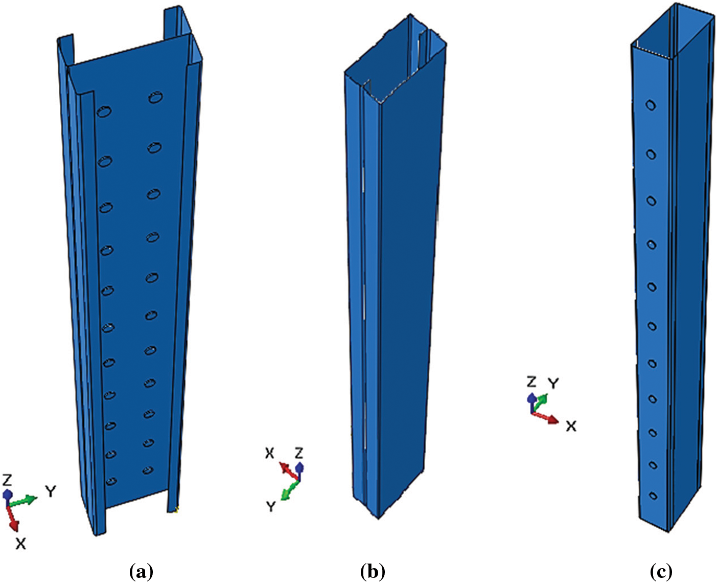
Figure 8: Numerical models of cold-formed built-up un-filled C-columns: (a) back-to-back; (b) face-to-face; (c) box
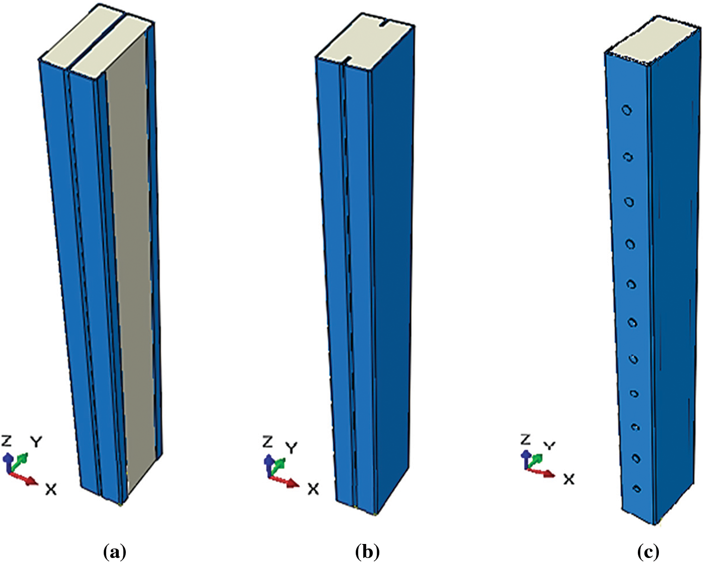
Figure 9: Numerical models of cold-formed built-up C-columns filled with concrete: (a) back-to-back partially encased with concrete; (b) face-to-face filled with concrete; (c) box filled with concrete
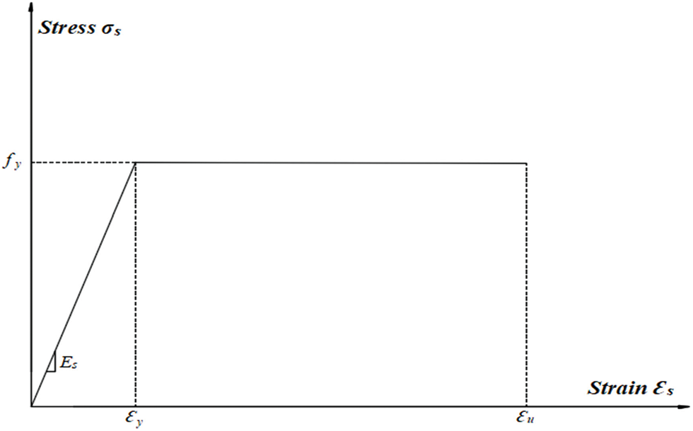
Figure 10: Stress-strain relationship of steel
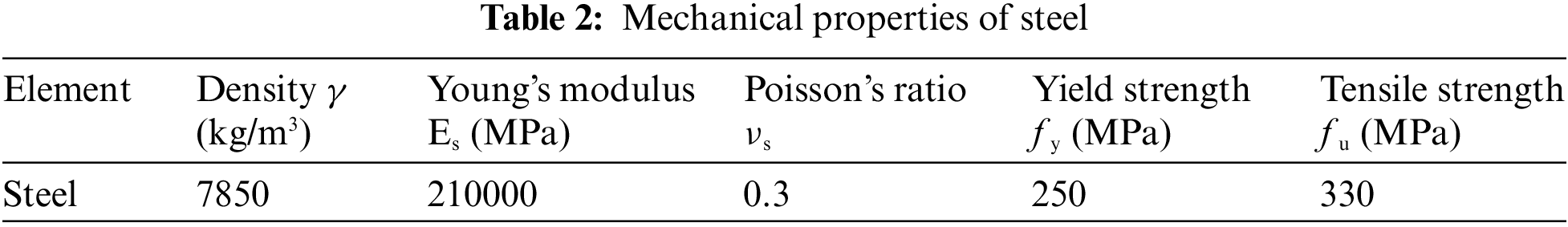

Table 2 shows the mechanical properties of the steel with a nuance of CR250 such that fy and fu are the yield and the tensile strengths of the steel, respectively. The nuance of the steel was extracted from the recommendations of EN 1993-1-3 [46].
Table 3 shows the mechanical properties of concrete strength class C25/30 such that fc is the associated compressive strength, fctm is the average tensile strength, and fctk 0.05, fctk 0.95 are the characteristic tensile strengths of concrete according to EN 1994-1-1 [45].
3.1 Loading and Boundary Conditions
In all models, as shown in Fig. 11, the lower rigid plate that contacts the end of the column was fixed in three translation directions (Ux, Uy, Uz), and the upper rigid plate, which contacts the top of the column, was fixed in two translation directions (Ux, Uy), allowing the Uz direction (column axis) to remain free for applying a displacement of 10 mm.
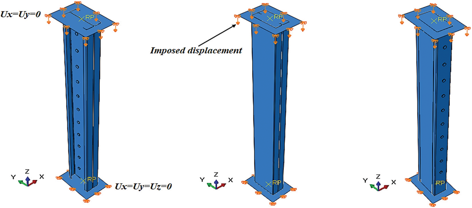
Figure 11: Loading and boundary conditions of C-section columns
3.2 Interaction Contact and Mesh
Contact interaction defines the pressure, adhesion (normal), and friction (tangential) stresses that arise from contact between deformable objects at common points or surfaces. In our study, the surface-to-surface contact interaction was adopted. For the interaction between C-profiles and the rivets, we used friction (penalty = 0.3) for tangential behavior and “hard contact” for normal behavior, as shown in Fig. 12a. On the other hand, in the steel-concrete interaction (Fig. 12b), we use friction (penalty = 0.25) [58] for tangential behavior and “hard contact” for normal behavior. For the interaction between the rigid plates, and the ends and tops of the columns, we used the “Tie” option (Fig. 12c). Additionally, the interaction between the rigid plates and the concrete at both ends (Fig. 12d) was set to “Rough” for tangential behavior and “hard contact” for normal behavior [32].

Figure 12: Contact interaction of cold-formed built-up C-section columns for (a) C-profiles-rivets interaction, (b) steel-concrete interaction, (c) plate-steel interaction, and (d) plate-concrete interaction
Regarding the finite element meshing of the models (Fig. 13), we adopted an R3D4-type mesh for the rigid plates. This mesh consisted of a 4-node 3-D bilinear rigid quadrilateral element as per the ABAQUS library [59]. For the columns and the concrete, we used the C3D8R element type, an 8-node linear brick solid element with three degrees of freedom at every node. Also, for the rivets, we employed the C3D10 element type, a 10-node quadratic tetrahedron. We conducted a sensitivity analysis to determine the optimal mesh size for achieving convergence to an exact solution. The selected mesh sizes were 1 mm for the rivets and 10 mm for the other components, including cold-formed columns, concrete, and plates.
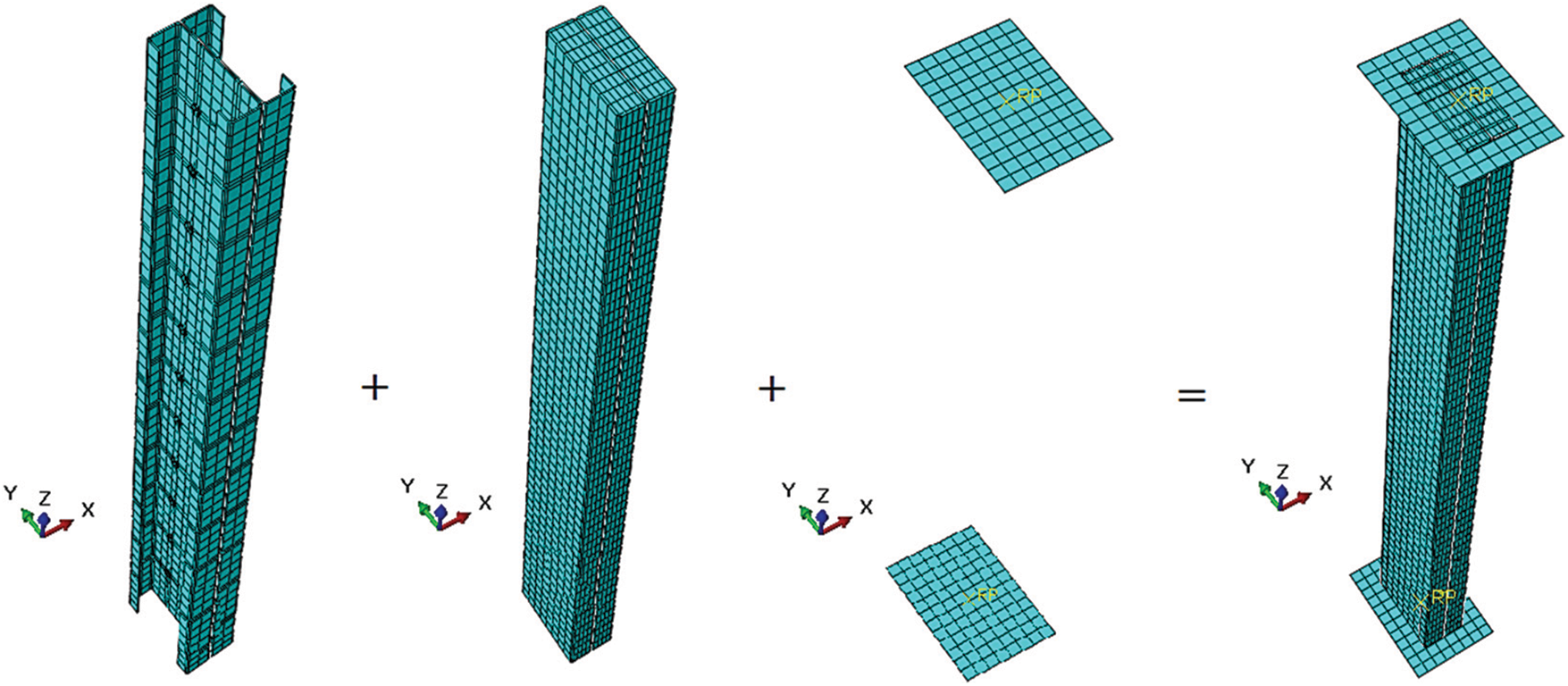
Figure 13: Mesh of cold-formed built-up C-section columns
4.1 Columns Un-Filled with Concrete
The understanding of the fundamental behavior of cold-formed structural assembled elements remains somewhat limited, and the assessment of their stability poses a challenging task. In examining the load-strain state in the middle of the un-filled back-to-back built-up columns according to different slenderness, our findings indicated that, up to a load of 80 kN, columns measuring 600, 1200, and 2000 mm exhibited similar elastic responses. However, beyond this threshold, plasticity became evident in these columns, leading to issues of elastic instabilities as has been confirmed in several reports in the literature such as the report by Roy et al. [19]. Notably, the 1800 mm column displayed negative compression deformations up to an 80 kN load, while the 1200 mm length column showed a maximum plastic deformation of approximately 5.03 × 10⁻³ (Fig. 14a).
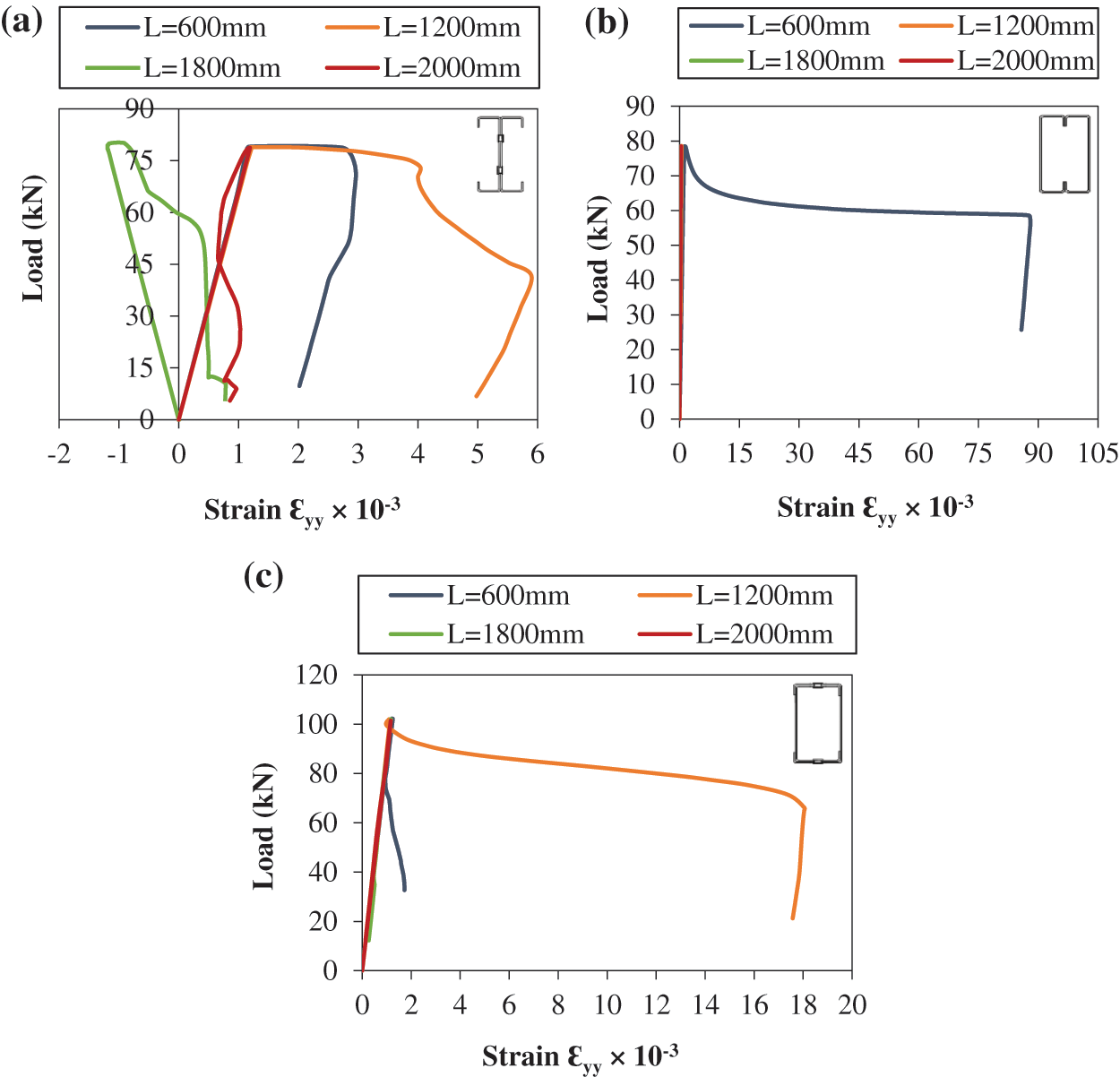
Figure 14: Load-strain states of cold-formed steel built-up un-filled C-columns: (a) Back-to-back; (b) face-to-face; (c) box
In the case of the face-to-face built-up model, the load-strain state at the midpoint revealed that the extension of the length could induce instability during the initial elastic phase, necessitating explicit consideration of both local and global buckling effects [60]. The shorter model presented a stiffness profile characterized by substantial plastic deformation of order 87.88 × 10⁻³, indicative of steel-yielding behavior (Fig. 14b).
The load-strain behavior in the middle of the box columns, as illustrated in Fig. 14c, demonstrated consistent linear responses across various slenderness ratios. However, a notable transition into plastic deformation was observed, with an amplitude of approximately 18.04 × 10⁻³ in the 1200 mm length column, mirroring the behavior observed in the back-to-back built-up columns. Interestingly, there was a significant 72.12% reduction in deformation in the back-to-back model when compared with the box model. Additionally, it was noteworthy that the box columns exhibited an increase in failure load by approximately 30% compared with the back-to-back and face-to-face models.
4.2 Columns Filled with Concrete
When investigating the columns after the concrete filling, specifically the load-strain behavior at the midsection of the cold-formed columns connected in a back-to-back configuration at varying lengths (Fig. 15a), a significant reduction in deformations was observed, accompanied by a twofold increase in strength when compared with the un-filled model with a load of P = 152 kN. This enhancement in performance was attributed to the synergistic interaction between the concrete core, which was confined by the outer shells, leading to increased stiffness and strength [37,61].
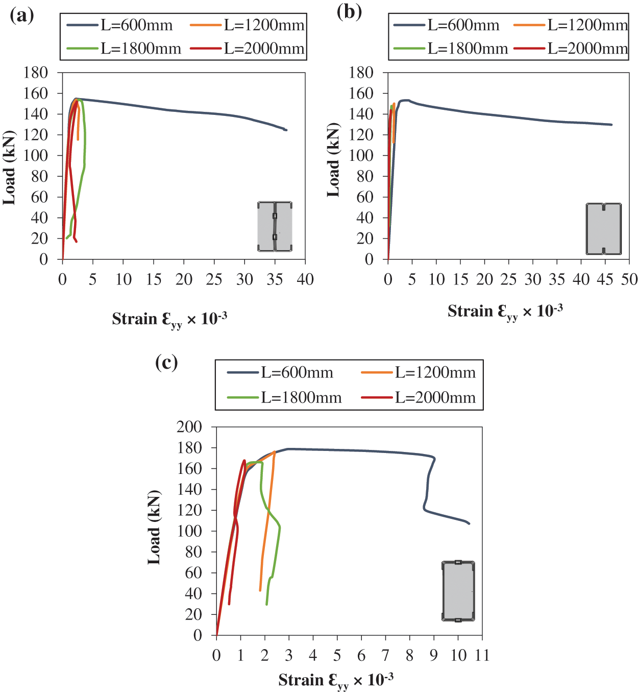
Figure 15: Load-strain states of cold-formed steel built-up C-columns filled with concrete: (a) Back-to-back partially encased with concrete; (b) face-to-face filled with concrete; (c) box filled with concrete
We observed that the behavior in the central region of the column, whether in a face-to-face configuration, either filled or un-filled, demonstrated a moderate influence that remained within a 40% range. This was evident from the similarity in the shapes of the load-strain curves in both cases, as shown in Figs. 14b and 15b. Depending on the slenderness, the columns exhibited instability characterized by outward local buckling in the web portion. The face-to-face model showcased a 19% increase in plasticity bearing compared with the back-to-back model, as presented in Fig. 15b.
The concrete-filled box configuration model showed a 16% boost in rigidity when contrasted with the other configurations, namely back-to-back and face-to-face. Notably, among the columns of different lengths, those measuring 600, 1200, and 1800 mm demonstrated elastoplastic behavior followed by instabilities. In contrast, the 2000 mm length column lost its instability at the first elasticity level (Fig. 15c).
4.3 Lateral Displacement of Columns
The columns exhibited distinct behaviors based on their slenderness, with high-slenderness columns tending to buckle within the elastic range, while those with intermediate slenderness were notably susceptible to imperfections. From a comparative analysis of cold-formed built-up columns in various 2000 mm length configurations, it was evident that these models experienced elastic instabilities. For un-filled columns (Fig. 16a), the maximum lateral displacement occurred at the mid-length (1000 mm) and manifested as global buckling in the face-to-face configuration and at 550 mm in the box configuration. The back-to-back configuration columns exhibited local buckling at lengths of 450 and 1200 mm.
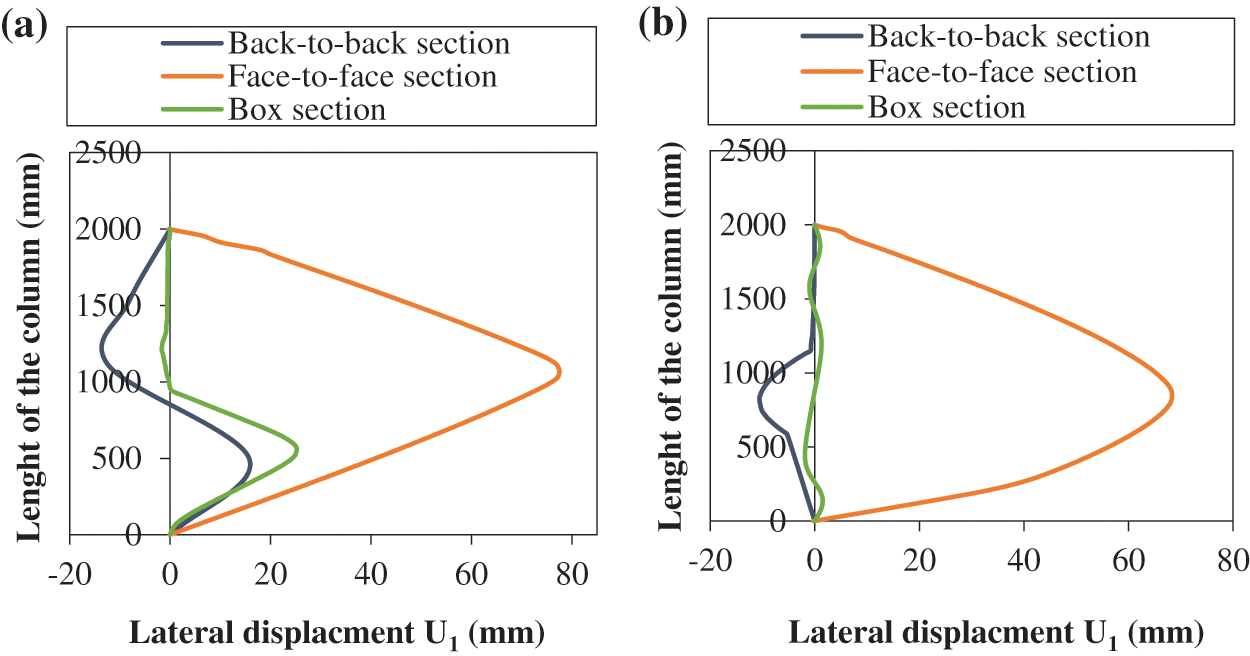
Figure 16: State of lateral displacement (U1) according to the length of C-section built-up columns (a) un-filled with concrete, and (b) filled with concrete
In contrast, concrete-filled columns (Fig. 16b) demonstrated a distinct behavior. Global buckling occurred at 800 mm for face-to-face columns under positive displacement (traction) and for back-to-back columns under negative displacement (compression). However, in the box configuration, there was a noticeable improvement when concrete was added, resulting in significantly reduced lateral displacement (a 92% reduction compared with the un-filled model). Furthermore, the concrete-filled model with a face-to-face configuration exhibited a 28.37% reduction in lateral displacement compared with its un-filled counterpart.
Due to the increasing complexity of cold-formed steel section shapes, the calculation of local buckling has become more complicated, and distortional buckling is of increasing importance. Local and distortional buckling can be considered as sectional buckling modes, and they can interact with each other, as well as with global buckling.
Fig. 17 and Table 4 present the failure modes of the cold-formed un-filled back-to-back C-columns at different lengths. It was noteworthy that all the columns experienced local buckling due to their relatively thin thickness, characterized by a rotation deformation without translation along the internal bending lines.

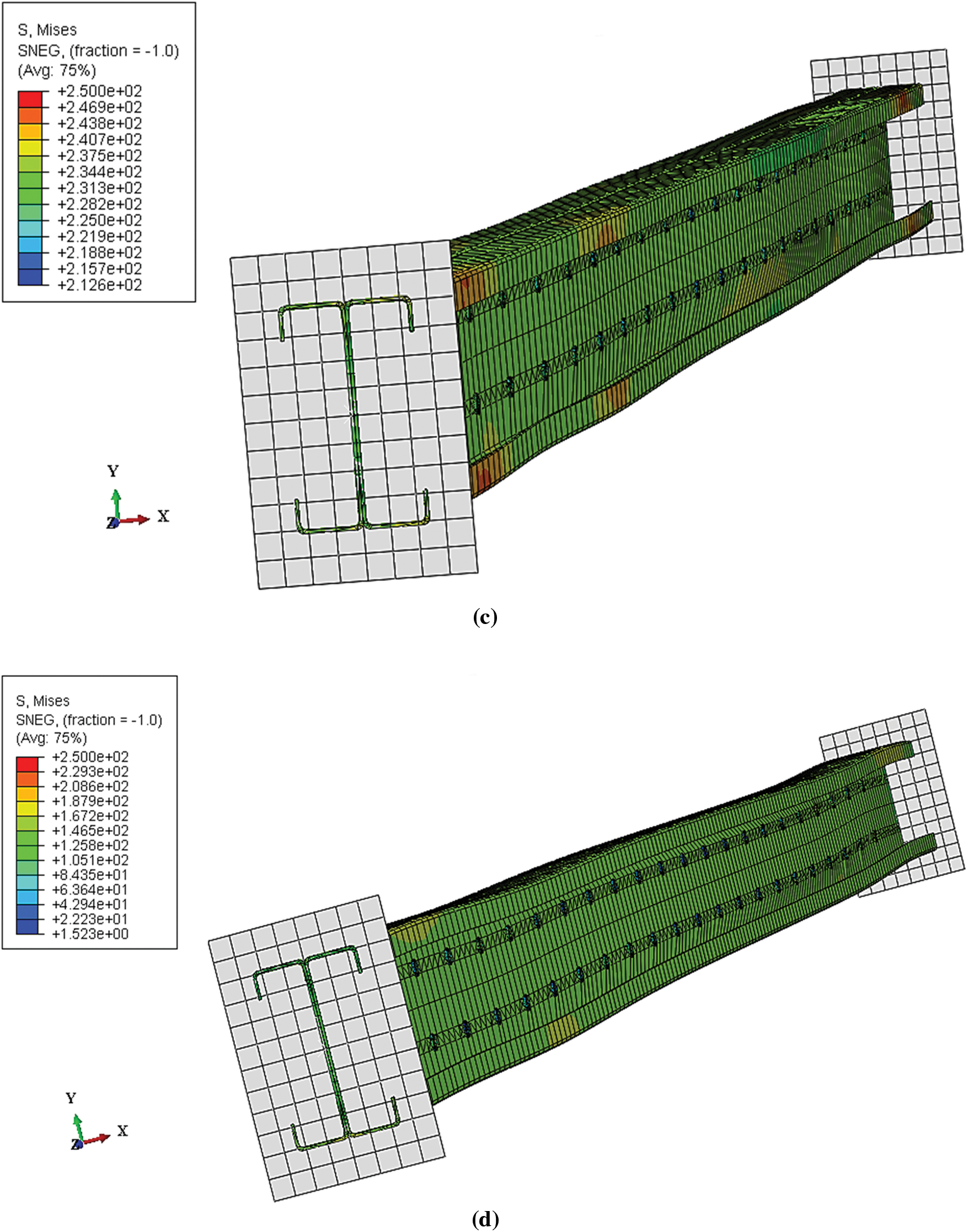
Figure 17: Failure modes of back-to-back C-section columns un-filled with concrete: (a) L = 600 mm; (b) L = 1200 mm; (c) L = 1800 mm; (d) L = 2000 mm

The cold-formed C-columns, connected back-to-back and partially encased with concrete at various lengths (Table 4), revealed that the 600 and 1200 mm columns experienced a mode of failure characterized as distortional buckling with disbonding between the contact surfaces of steel and concrete, i.e., buckling of the fallen edges towards the outside, as shown in Figs. 18a and 18b. In contrast, the 1800 and 2000 mm columns exhibited global instability demonstrated by buckling (Figs. 18c and 18d).


Figure 18: Failure modes of back-to-back C-section columns partially encased with concrete: (a) L = 600 mm; (b) L = 1200 mm; (c) L = 1800 mm; (d) L = 2000 mm
While studying the failure modes of face-to-face un-filled and concrete-filled built-up columns with a length of 2000 mm, we observed global buckling instability. Compressive deformations do not always play a decisive role in vertical structural elements. On the other hand, buckling is a form of instability specific to slender compressed elements, which occurs at a certain load and depends on the relationship between the cross-section and height of the element in consideration. The face-to-face C-profile configuration offers advantages, especially when concrete is added. In practice, this setup eliminated the need for formwork and ensured complete containment of concrete, protecting its external surface from external forces or aggression, as observed in Fig. 19 and Table 4.
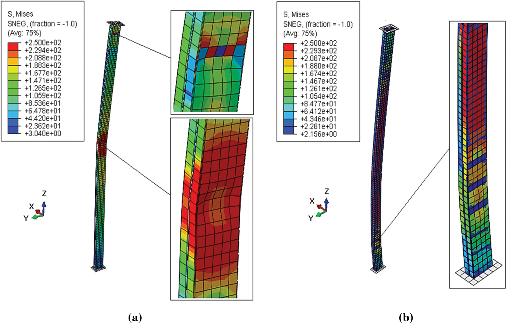
Figure 19: Failure modes of face-to-face C-section columns of 2000 mm length (a) un-filled with concrete, and (b) filled with concrete
There was an improvement in the failure mode of the concrete-filled box model (Fig. 20b) compared with the un-filled model which showed global buckling instability (Fig. 20a).
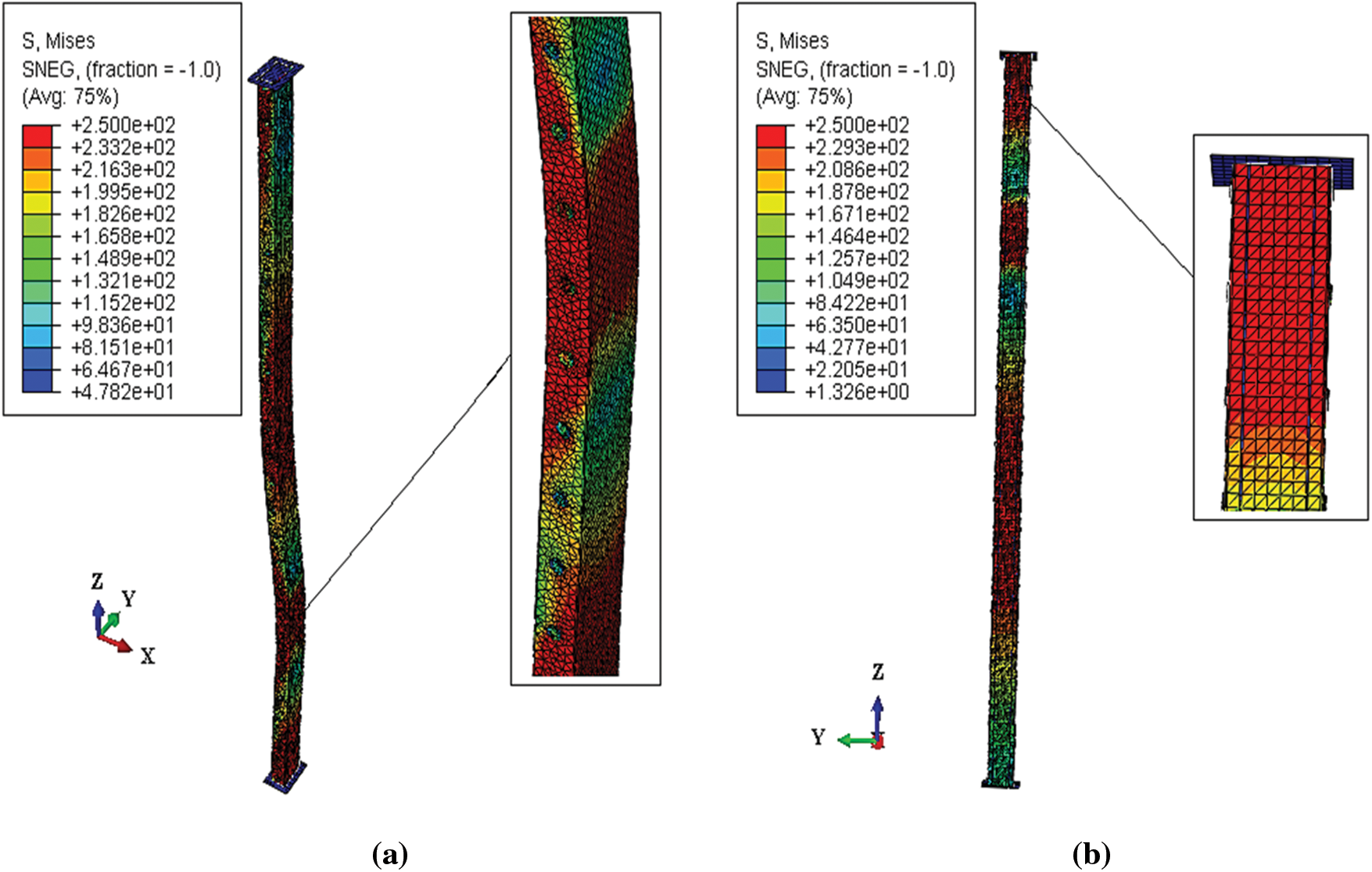
Figure 20: Failure modes of box C-section columns of 2000 mm length (a) un-filled with concrete and (b) filled with concrete
The validation of the obtained results was conducted by comparing them to the failure loads determined by Eurocode 4, which provides guidelines for the elastic bending rigidities of mixed cross-sections (steel-concrete). Eq. (12) was applied to mixed columns encased in concrete, such as the back-to-back model, while Eq. (13) was used for concrete-filled models like the face-to-face and box models.
Table 4 summarizes all the analytical results based on Eurocode 3 and Eurocode 4, alongside the numerical results for both un-filled and concrete-filled steel columns, including their instability modes. We noted a very good agreement between these results, with a minor difference not exceeding 8%. This discrepancy was attributed to the consideration of interaction effects between surfaces in the numerical models, as validated by ABAQUS software. In the back-to-back and face-to-face models, the ultimate loads were very similar, whereas the box model exhibited a notable increase in ultimate load of about 30% for the un-filled models and 16% for the concrete-filled models.
Fig. 21 presents a comparative study of the analytical and numerical results for un-filled and concrete-filled cold-formed columns of different lengths with various configurations, using graphical histograms; back-to-back (Fig. 21a), face-to-face (Fig. 21b), and box (Fig. 21c). For the different lengths, we noted a strong correlation between the analytical and numerical results for both un-filled and concrete-filled columns, with only a slight difference not exceeding 8%. The critical load of models with back-to-back (Fig. 21a) and face-to-face (Fig. 21b) un-filled configurations closely approximated that of the box configuration (Fig. 21c), which increased by approximately 30% due to the stiffening of the flanges, playing a crucial role in enhancing resistance. Compared with un-filled columns, the ultimate load nearly doubled in concrete-filled columns, representing a 48% increase, primarily due to the interaction between steel and concrete, which enhanced confinement effects, thus improving column strength and rigidity.
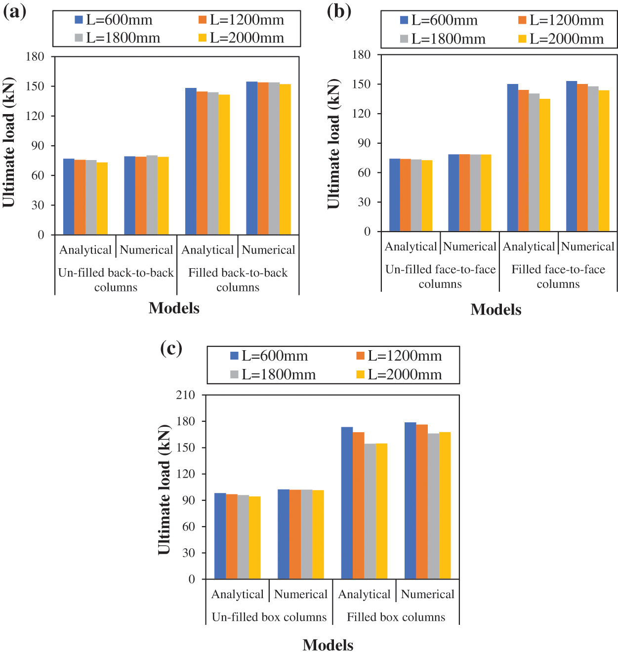
Figure 21: Comparison between analytical and numerical results of the studied models at different lengths for (a) back-to-back, (b) face-to-face, and (c) box configuration of columns
5 Conclusions and Recommendations
This paper presented a finite element numerical study of built-up cold-formed C-columns with different configurations, including back-to-back, face-to-face, and box. High-grade concrete was employed to fill these columns, inducing compressive stresses and resistance. The concrete confinement effect was considered, particularly for the face-to-face and box configurations. The critical load values analytically calculated based on the Eurocode 3 and Eurocode 4 standards were compared based on the numerical results obtained. The main conclusions were:
• For 2000 mm length un-filled columns, the maximum lateral displacement occurred in the middle for the face-to-face configuration, and at 550 mm for the box configuration. Local buckling was observed in the back-to-back configuration columns at lengths of 450 and 1200 mm.
• It was noteworthy that the un-filled box columns exhibited an increase in failure load by approximately 30% compared with the back-to-back and face-to-face models.
• The results indicated that the proposed models provide a dependable and efficient means of assessing the stability of doubly constructed columns across different configurations, with a focus on measuring lateral displacement. These models could effectively capture various types of instability, including local, distortional, and global buckling, in cold-formed built-up columns.
• In contrast to un-filled built-up columns, assembled columns filled with concrete exhibited a significant decrease in deformations and a twofold increase in bearing capacity.
• The addition of concrete to the interior of the cold-formed built-up columns significantly increased their structural strength, providing a larger load capacity and improved resistance to compressive pressures. This combination of cold-formed steel and concrete enhanced their performance.
• Face-to-face configuration columns either filled or un-filled with concrete demonstrated a moderate influence that remained within a 40% range.
• According to the histograms, the box column demonstrated an increase in ultimate load of approximately 30% when un-filled and 16% when filled, compared with the other models. This increase was attributed to the stiffness of the flanges, which played a crucial role in enhancing resistance.
• Among the models studied, the concrete-filled box model indicated optimal behavior in terms of minimizing imperfections arising from elastic instabilities when compared with the other models.
• There was a very good correlation, with differences of no more than 8%, between numerical and analytical results. Further investigation will be conducted to assess the influence of other factors, such as the b/t ratio of assembled sections with different slenderness and the use of different types of concrete, on the bearing capacity of built-up columns.
Acknowledgement: None.
Funding Statement: The authors received their funding from Ahmed Farouk Deifalla. Email: ahmed.deifallah@fue.edu.e.g.
Author Contributions: Conceptualization, Oulfa Harrat, Yazid Hadidane, S. M. Anas, Nadhim Hamah Sor and Nadia Gouider; Data curation, Oulfa Harrat; Formal analysis, Oulfa Harrat and Yazid Hadidane; Funding acquisition, Ahmed Farouk Deifalla and Paul O. Awoyera; Investigation, Oulfa Harrat and Yazid Hadidane; Methodology, Oulfa Harrat, Yazid Hadidane, S. M. Anas and Nadhim Hamah Sor; Project administration, Nadia Gouider; Resources, Oulfa Harrat, Yazid Hadidane, S. M. Anas, Nadhim Hamah Sor, Ahmed Farouk Deifalla, Paul O. Awoyera and Nadia Gouider; Software, Oulfa Harrat, Yazid Hadidane, S. M. Anas and Nadhim Hamah Sor; Supervision, S. M. Anas and Nadia Gouider; Validation, Oulfa Harrat, Yazid Hadidane, S. M. Anas, Nadhim Hamah Sor, Ahmed Farouk Deifalla, Paul O. Awoyera and Nadia Gouider; Visualization, S. M. Anas, Nadhim Hamah Sor, Ahmed Farouk Deifalla, Paul O. Awoyera and Nadia Gouider; Writing–original draft, Oulfa Harrat, Yazid Hadidane, S. M. Anas, Nadhim Hamah Sor, Ahmed Farouk Deifalla, Paul O. Awoyera and Nadia Gouider,; Writing–review & editing, Oulfa Harrat, Nadhim Hamah Sor and Nadia Gouider. All authors reviewed the results and approved the final version of the manuscript.
Availability of Data and Materials: Not applicable.
Conflicts of Interest: The authors declare that they have no conflicts of interest to report regarding the present study.
References
1. Roy, K., Ting, T. C. H., Lau, H. H., Lim, J. B. P. (2018). Nonlinear behavior of axially loaded back-to- back built-up cold-formed steel un-lipped channel sections. Steel and Composite Structures, 28(2), 233–250. https://doi.org/10.12989/SCS.2018.28.2.233 [Google Scholar] [CrossRef]
2. Gurupatham, B. G. A., Roy, K., Raftery, G. M., Lim, J. B. P. (2022). Influence of intermediate stiffeners on axial capacity of thin-walled built-up open and closed channel section columns. Buildings, 12(8), 1071. https://doi.org/10.3390/buildings12081071 [Google Scholar] [CrossRef]
3. Craveiro, H. D., Rodrigues, J. P. C., Laím, L. (2016). Buckling resistance of axially loaded cold-formed steel columns. Thin-Walled Structures, 106, 358–375. https://doi.org/10.1016/j.tws.2016.05.010 [Google Scholar] [CrossRef]
4. Ananthi, G. B., Roy, K., Lim, J. (2022). Experimental and numerical study of an innovative 4-channels cold-formed steel built-up column under axial compression. Steel and Composite Structures, 42(4), 513–538. [Google Scholar]
5. Faridmehr, I., Osman, M. H., Tahir, M. M., Azimi, M., Gholami, M. (2016). Behaviour and design of cold-formed steel C-sections with cover plates under bending. International Journal of Steel Structures, 16(2), 587–600. https://doi.org/10.1007/s13296-016-6026-9 [Google Scholar] [CrossRef]
6. Dar, A. R. (2021). Bending response of cold-formed steel built-up beams with overlapped flanges in stiffened channels. Innovative Infrastructure Solutions, 6(3), 175. https://doi.org/10.1007/s41062-021-00546-5 [Google Scholar] [CrossRef]
7. Kouider, N., Hadidane, Y., Benzerara, M. (2021). Numerical investigation of the cold-formed I-beams bending strength with different web shapes. Frattura ed Integrità Strutturale, 16(59), 153–171. https://doi.org/10.3221/IGF-ESIS.59.12 [Google Scholar] [CrossRef]
8. Alex, J., Iyappan, G. (2016). Experimental study on flexural behaviour of cold formed steel section. International Journal of Innovative Research in Science Engineering, 40, 219–222. [Google Scholar]
9. Mansuri, S., Parmar, K. (2017). Numerical investigation of flexural strength of cold form built-up beams. International Journal of Advanced Research in Science, Engineering and Technology, 6(1), 109–116. [Google Scholar]
10. Preethi, T., Rajkumar, P. R. K., Jegan, M. (2020). Investigation on the flexural behaviour of steel cold formed built up sections. International Journal of Integrated Engineering, 12(9), 184–190. https://doi.org/10.30880/ijie.2020.12.022 [Google Scholar] [CrossRef]
11. Hadidane, Y., Kouider, N., Benzerara, M. (2022). Flexural behavior of delta and bi-delta cold-formed steel beams: Experimental investigation and numerical analysis. Frattura ed Integrità Strutturale, 16(61), 69–88. https://doi.org/10.3221/IGF-ESIS.61.05 [Google Scholar] [CrossRef]
12. Yao, X., Yang, J., Guo, Y. (2023). Study on restoring force model of cold-formed thin-walled steel lipped channel beam-columns under cyclic load. Buildings, 13(1), 114. https://doi.org/10.3390/buildings13010114 [Google Scholar] [CrossRef]
13. Sujitha, R., Sunmathi, N., Manikandan, R. K., Arunprasad, J., Rajkumar, S. et al. (2022). Analytical and experimental study on cold-formed steel built-up sections for bending. Materials, 15(20), 7140. https://doi.org/10.3390/ma15207140 [Google Scholar] [PubMed] [CrossRef]
14. Manikandan, P., Sukumar, S., Balaji, T. U. (2014). Effective shaping of cold-formed thin-walled built-up beams in pure bending. Arabian Journal for Science and Engineering, 39(8), 6043–6054. https://doi.org/10.1007/s13369-014-1261-x [Google Scholar] [CrossRef]
15. Anbarasu, M., Kanagarasu, K., Sukumar, S. (2015). Investigation on the behaviour and strength of cold-formed steel web stiffened built-up battened columns. Materials and Structures, 48(12), 4029–4038. https://doi.org/10.1617/s11527-014-0463-8 [Google Scholar] [CrossRef]
16. El Aghoury, M. A., Tawfic, M., Amoush, E. (2020). Compressive strength of axially loaded built-up sigma cold formed sections columns. Future Engineering Journal, 1(1), 2314–7237. [Google Scholar]
17. Dar, M. A., Subramanian, N., Dar, A. R., Anbarasu, M., Lim, J. B. et al. (2019). Behaviour of partly stiffened cold-formed steel built-up beams: Experimental investigation and numerical validation. Advances in Structural Engineering, 22(1), 172–186. https://doi.org/10.1177/1369433218782767 [Google Scholar] [CrossRef]
18. Ghannam, M. (2017). Axial load capacity of cold-formed steel built-up stub columns. International Journal of Steel Structures, 17(4), 1273–1283. https://doi.org/10.1007/s13296-017-1202-0 [Google Scholar] [CrossRef]
19. Roy, K., Ting, T. C. H., Lau, H. H., Lim, J. B. P. (2018). Effect of thickness on the behaviour of axially loaded back-to-back cold-formed steel built-up channel sections-experimental and numerical investigation. Structures, 16, 327–346. https://doi.org/10.1016/j.istruc.2018.09.009 [Google Scholar] [CrossRef]
20. Kanthasamy, E., Hussain, J., Thirunavukkarasu, K., Poologanathan, K., Roy, K. et al. (2022). Flexural behaviour of built-up beams made of optimised sections. Buildings, 12(11), 1868. https://doi.org/10.3390/buildings12111868 [Google Scholar] [CrossRef]
21. Anbarasu, M. (2019). Numerical investigation on behaviour and design of cold-formed steel built-up column composed of lipped sigma channels. Advances in Structural Engineering, 22(8), 1817–1829. https://doi.org/10.1177/1369433218824499 [Google Scholar] [CrossRef]
22. Yu, C., Schafer, B. W. (2006). Distortional buckling tests on cold-formed steel beams. Journal of Structural Engineering, 132(4), 515–528. https://doi.org/10.1061/(ASCE)0733-9445(2006)132:4(515) [Google Scholar] [CrossRef]
23. Manikandan, P., Sukumar, S. (2015). Behaviour of stiffened cold-formed steel built-up sections with complex edge stiffeners under bending. KSCE Journal of Civil Engineering, 19(7), 2108–2115. https://doi.org/10.1007/s12205-015-1221-3 [Google Scholar] [CrossRef]
24. Ye, J., Mojtabaei, S. M., Hajirasouliha, I., Shepherd, P., Pilakoutas, K. (2018). Strength and deflection behaviour of cold-formed steel back-to-back channels. Engineering Structures, 177, 641–654. https://doi.org/10.1016/j.engstruct.2018.09.064 [Google Scholar] [CrossRef]
25. Ghannam, M. (2019). Bending moment capacity of cold-formed steel built-up beams. International Journal of Steel Structures, 19(2), 660–671. https://doi.org/10.1007/s13296-018-0155-2 [Google Scholar] [CrossRef]
26. Moen, C. D., Schafer, B. W. (2009). Elastic buckling of cold-formed steel columns and beams with holes. Engineering Structures, 31(12), 2812–2824. https://doi.org/10.1016/j.engstruct.2009.07.007 [Google Scholar] [CrossRef]
27. Ali, R. B., Islam, Md. M., Begum, M., Rahman, Md. S. (2021). Behavior of concrete-filled steel tubular cold-formed built-up slender square columns under eccentric compression. Innovative Infrastructure Solutions, 6(4), 189. https://doi.org/10.1007/s41062-021-00552-7 [Google Scholar] [CrossRef]
28. More, F. M. D. S., Subramanian, S. S. (2023). Experimental investigation on the axial compressive behaviour of cold-formed steel-concrete composite columns infilled with various types of fibre-reinforced concrete. Buildings, 13(1), 151. https://doi.org/10.3390/buildings13010151 [Google Scholar] [CrossRef]
29. Jiang, L., Wang, W., Ji, J., Ren, H., Wang, Q. et al. (2022). Bearing behavior of high-performance concrete-filled high-strength steel tube composite columns subjected to eccentrical load. Frontiers in Materials, 9, 972811. https://doi.org/10.3389/fmats.2022.972811 [Google Scholar] [CrossRef]
30. Ishizawa, T., Iura, M. (2006). Analysis of partially concrete-filled steel tubular columns subjected to cyclic loadings. Computer Modeling in Engineering & Sciences, 11(3), 121–130. https://doi.org/10.3970/cmes.2006.011.121 [Google Scholar] [CrossRef]
31. Hu, H. T., Huang, C. S., Wu, M. H., Wu, Y. M. (2003). Nonlinear analysis of axially loaded concrete-filled tube columns with confinement effect. Journal of Structural Engineering, 129(10), 1322–1329. https://doi.org/10.1061/(ASCE)0733-9445(2003)129:10(1322) [Google Scholar] [CrossRef]
32. Dai, X., Lam, D. (2010). Numerical modelling of the axial compressive behaviour of short concrete-filled elliptical steel columns. Journal of Constructional Steel Research, 66(7), 931–942. https://doi.org/10.1016/j.jcsr.2010.02.003 [Google Scholar] [CrossRef]
33. He, L., Lin, S., Jiang, H. (2019). Confinement effect of concrete-filled steel tube columns with infill concrete of different strength grades. Frontiers in Materials, 6, 71. https://doi.org/10.3389/fmats.2019.00071 [Google Scholar] [CrossRef]
34. Liu, Y., Lyu, F., Ding, F., Wang, E., Xu, Y. et al. (2021). Numerical study on confinement effect and efficiency of concentrically loaded RACFRST stub columns. Frontiers in Materials, 8, 630774. https://doi.org/10.3389/fmats.2021.630774 [Google Scholar] [CrossRef]
35. Boulmaali-Hacene Chaouche, Y., Kouider, N., Djeghaba, K., Kebaili, B. (2022). Numerical study of the plasticity effect on the behavior of short steel columns filled with concrete loaded axially. Frattura ed Integrità Strutturale, 16(62), 91–106. https://doi.org/10.3221/IGF-ESIS.62.07 [Google Scholar] [CrossRef]
36. Rahnavard, R., Craveiro, H. D., Lopes, M., Simões, R. A., Laím, L. et al. (2022). Concrete-filled cold-formed steel (CF-CFS) built-up columns under compression: Test and design. Thin-Walled Structures, 179, 109603. https://doi.org/10.1016/j.tws.2022.109603 [Google Scholar] [CrossRef]
37. Rahnavard, R., Craveiro, H. D., Simões, R. A., Laím, L., Santiago, A. (2022). Buckling resistance of concrete-filled cold-formed steel (CF-CFS) built-up short columns under compression. Thin-Walled Structures, 170, 108638. https://doi.org/10.1016/j.tws.2021.108638 [Google Scholar] [CrossRef]
38. Rahnavard, R., Craveiro, H. D., Simões, R. A., Laím, L., Santiago, A. (2022). Fire resistance of concrete-filled cold-formed steel (CF-CFS) built-up short columns. Journal of Building Engineering, 48, 103854. https://doi.org/10.1016/j.jobe.2021.103854 [Google Scholar] [CrossRef]
39. Rahnavard, R., Craveiro, H. D., Simões, R. A., Santiago, A. (2022). Equivalent temperature prediction for concrete-filled cold-formed steel (CF-CFS) built-up column sections (part A). Case Studies in Thermal Engineering, 33, 101928. https://doi.org/10.1016/j.csite.2022.101928 [Google Scholar] [CrossRef]
40. Rahnavard, R., Craveiro, H. D., Simões, R. A., Santiago, A. (2022). Equivalent temperature prediction for concrete-filled cold-formed steel (CF-CFS) built-up column sections (part B). Case Studies in Thermal Engineering, 35, 102111. https://doi.org/10.1016/j.csite.2022.102111 [Google Scholar] [CrossRef]
41. Craveiro, H. D., Rahnavard, R., Henriques, J., Simões, R. A. (2022). Structural fire performance of concrete-filled built-up cold-formed steel columns. Materials, 15(6), 2159. https://doi.org/10.3390/ma15062159 [Google Scholar] [PubMed] [CrossRef]
42. Chen, M. T., Zhang, T., Young, B. (2023). Behavior of concrete-filled cold-formed steel built-up section stub columns. Thin-Walled Structures, 187, 110692. https://doi.org/10.1016/j.tws.2023.110692 [Google Scholar] [CrossRef]
43. Teoh, K. B., Chua, Y. S., Pang, S. D., Kong, S. Y. (2023). Experimental investigation of lightweight aggregate concrete-filled cold-formed built-up box section (CFBBS) stub columns under axial compression. Engineering Structures, 279, 115630. https://doi.org/10.1016/j.engstruct.2023.115630 [Google Scholar] [CrossRef]
44. Senthilkumar, R., D, M., D. R, S., B, A., Avudaiappan, S. et al. (2022). Behaviour of cold-formed steel-concrete composite columns under axial compression: Experimental and numerical study. Structures, 44, 487–502. https://doi.org/10.1016/j.istruc.2022.07.086 [Google Scholar] [CrossRef]
45. Eurocode 4 (2004). Design of composite steel and concrete structures–Part 1-1: General rules and rules for buildings. European Committee for Standardization EN1994-1-1. [Google Scholar]
46. European Committee for Standardization (2006). Eurocode 3: Design of steel structures–Part 1-3: General rules—Supplementary rules for cold-formed members and sheeting. EN 1993-1-3. [Google Scholar]
47. ACI Committee (1999). Building code requirements for structural concrete (ACI 318-99) and commentary (ACI 318r-99). American Concrete Institute. [Google Scholar]
48. Mander, J. B., Priestley, M. J. N., Park, R. (1988). Theoretical stress-strain model for confined concrete. Journal of Structural Engineering, 114(8), 1804–1826. https://doi.org/10.1061/(ASCE)0733-9445(1988)114:8(1804) [Google Scholar] [CrossRef]
49. Richart, F. E., Brandtzæg, A., Brown, R. L. (1928). A study of the failure of concrete under combined compressive stresses. USA: University of Illinois at Urbana Champaign, College of Engineering. [Google Scholar]
50. Mulligan, G. P., Pekoz, T. (1987). Local buckling interaction in cold-formed columns. Journal of Structural Engineering, 113(3), 604–620. https://doi.org/10.1061/(ASCE)0733-9445(1987)113:3(604) [Google Scholar] [CrossRef]
51. Mulligan, G. P. (1983). The influence of local buckling on the structural behavior of singly-symmetric cold- formed steel columns. USA: Cornell University. [Google Scholar]
52. Morkhade, S. G., Shaikh, S., Kumbhar, A., Shaikh, A., Tiwari, R. (2018). Comparative study of ultimate load for castellated and plain-webbed beams. International Journal of Civil Engineering and Technology, 9(8), 1466–1476. [Google Scholar]
53. Anas, S. M., Alam, M., Umair, M. (2021). Experimental and numerical investigations on performance of reinforced concrete slabs under explosive-induced air-blast loading: A state-of-the-art review. Structures, 31, 428–461. https://doi.org/10.1016/j.istruc.2021.01.102 [Google Scholar] [CrossRef]
54. Hedayati, E., Vahedi, M. (2017). Numerical investigation of penetration in ceramic/aluminum targets using smoothed particle hydrodynamics method and presenting a modified analytical model. Computer Modeling in Engineering & Sciences, 113(3), 295–323. https://doi.org/10.3970/cmes.2017.113.307 [Google Scholar] [CrossRef]
55. Zhou, T., Li, Y., Ren, L., Sang, L., Zhang, L. (2021). Research on the elastic buckling of composite webs in cold-formed steel back-to-back built-up columns–Part I: Experimental and numerical investigation. Structures, 30, 115–133. https://doi.org/10.1016/j.istruc.2020.12.059 [Google Scholar] [CrossRef]
56. Wu, Z., Guo, L., Hong, J. (2023). Improved staggered algorithm for phase-field brittle fracture with the local arc-length method. Computer Modeling in Engineering & Sciences, 134(1), 611–636. https://doi.org/10.32604/cmes.2022.020694 [Google Scholar] [CrossRef]
57. Han, F., Li, Z., Zhang, J., Liu, Z., Yao, C. et al. (2023). ABAQUS and ANSYS implementations of the peridynamics-based finite element method (PeriFEM) for brittle fractures. Computer Modeling in Engineering & Sciences, 136(3), 2715–2740. https://doi.org/10.32604/cmes.2023.026922 [Google Scholar] [CrossRef]
58. Ellobody, E., Young, B. (2006). Design and behaviour of concrete-filled cold-formed stainless steel tube columns. Engineering Structures, 28(5), 716–728. https://doi.org/10.1016/j.engstruct.2005.09.023 [Google Scholar] [CrossRef]
59. Duval, A., Al-akhras, H., Maurin, F., Elguedj, T., Duval, A. et al. (2014). Abaqus/CAE 6.14 user’s manual. USA: Dassault Systémes Inc. [Google Scholar]
60. Beulah Gnana Ananthi, G., Ashvini, B. (2019). Experimental theoretical and numerical studies on cold-formed steel stub channel columns with stiffeners. Asian Journal of Civil Engineering, 20(2), 171–185. https://doi.org/10.1007/s42107-018-0096-2 [Google Scholar] [CrossRef]
61. Zeghiche, J., Chaoui, K. (2005). An experimental behaviour of concrete-filled steel tubular columns. Journal of Constructional Steel Research, 61(1), 53–66. https://doi.org/10.1016/j.jcsr.2004.06.006 [Google Scholar] [CrossRef]
Cite This Article
 Copyright © 2024 The Author(s). Published by Tech Science Press.
This work is licensed under a Creative Commons Attribution 4.0 International License , which permits unrestricted use, distribution, and reproduction in any medium, provided the original work is properly cited.
 Downloads
 Citation Tools