
 Submit a Paper
 Propose a Special lssue
 Open Access
ARTICLE
A Method for Ultrasound Servo Tracking of Puncture Needle
1 School of Artificial Intelligence, Guangzhou Huashang College, Guangzhou, 511300, China
2 School of Automation, University of Electronic Science and Technology of China, Chengdu, 610054, China
3 Department of Electronics, Information and Bioengineering (DEIB), Politecnico di Milano, Via Ponzio 34/5, Milan, 20133, Italy
4 Department of Modelling, Simulation, and Visualization Engineering, Old Dominion University, Norfolk, VA 23529, USA
5 Graduate School of Engineering, ESIGELEC, Av. Galilée, St Etienne du Rouvray, 76801, France
6 Department of Computer Science and Engineering, Hanyang University, Ansan, 15577, Republic of Korea
* Corresponding Authors: Bo Yang. Email: ; Jiawei Tian. Email:
(This article belongs to the Special Issue: Emerging Artificial Intelligence Technologies and Applications)
Computer Modeling in Engineering & Sciences 2025, 144(2), 2287-2306. https://doi.org/10.32604/cmes.2025.066195
Received 01 April 2025; Accepted 19 June 2025; Issue published 31 August 2025
 View Full Text
 Download PDF
Abstract
Computer-aided surgical navigation technology helps and guides doctors to complete the operation smoothly, which simulates the whole surgical environment with computer technology, and then visualizes the whole operation link in three dimensions. At present, common image-guided surgical techniques such as computed tomography (CT) and X-ray imaging (X-ray) will cause radiation damage to the human body during the imaging process. To address this, we propose a novel Extended Kalman filter-based model that tracks the puncture needle-point using an ultrasound probe. To address the limitations of Kalman filtering methods based on position and velocity, our method of Kalman filtering uses the position and relative velocity of the puncture needle-point instead, and the ultrasonic probe is controlled by a Proportional Integral (PI) controller in X-axis direction and Proportional Derivative (PD) controller in the Y-axis direction. The motion of the ultrasonic probe can be servo-controlled by whether the image information of the puncture needle-point can be detected by the ultrasonic image so that the ultrasonic probe can track the puncture needle-point in real time. The experiment results show that this method has better tracking performance.Keywords
Computer-assisted surgical systems encompass a confluence of interdisciplinary domains including computer science, information management, communication technology, mechanics, and image processing [1–5]. Their principal objective resides in the emulation of the comprehensive surgical milieu through computer technologies, thereby guiding and supporting surgeons in the successful execution of surgical procedures. Foremost among these systems is image-guided surgery [6], an emerging technique in minimally invasive medical interventions that leverages multimodal medical imaging to facilitate preoperative surgical path planning. This entails real-time imaging modalities like ultrasound imaging, necessitating the integration of tracking and localization apparatus during surgical procedures to ascertain the spatial coordinates and orientations of surgical probes and lesions. The resultant real-time spatial data is then co-registered with preoperative images, presenting a virtual amalgamation within the same coordinate framework. This virtual alignment furnishes surgeons with real-time navigational insights, enhancing tasks such as the precise placement of surgical probes to minimize collateral damage.
Ultrasound (US) imaging, grounded in ultrasound wave propagation, acquires internal organ images by processing the reflected signals obtained through scanning the human body [7,8]. This pioneering effort materialized in clinical settings, signifying the maturation of ultrasound-based navigation for clinical practice. Notably, in contemporary minimally invasive procedures like radiofrequency ablation and biopsy surgeries [9], two-dimensional ultrasound images supplant other imaging modalities such as CT scans, mitigating radiation exposure while delivering real-time intraoperative visuals. Nevertheless, the utility of two-dimensional ultrasound is hindered by volumetric limitations that engender imprecise target localization and varying procedural risks.
In numerous minimally invasive medical interventions, the introduction of needles into tissue constitutes a crucial diagnostic and treatment modality. The accuracy of needle tip placement critically underpins procedural success. Deviations in needle tip positioning can engender misdiagnosis (e.g., biopsy) or hinder effective treatment (e.g., radiotherapy) [10,11]. Imaging-guided needle insertion relies on techniques encompassing computed tomography (CT) scans, fluoroscopy, magnetic resonance imaging (MRI), and ultrasound imaging. The deployment of CT, however, is marred by heightened ionizing radiation exposure for patients [12]. Furthermore, CT-guided interventions are limited to instruments fabricated from non-magnetic and dielectric materials [13]. In contrast, ultrasound stands as a benign and easily accessible imaging modality, facilitating real-time visualization of needles and target lesions during surgical procedures [14,15].
Presently, the efficacy of two-dimensional ultrasound imagery falters in the accurate delineation of spatial lesion data, often succumbing to partial volume artifacts [16]. These artifacts arise due to the concurrent visualization of echoes from adjacent tissues anterior and posterior to the lesion within the same image. Consequently, these extraneous echoes interfere with the unobstructed observation of the lesion, thereby engendering partial volume artifacts [17] within two-dimensional ultrasound scans. Five primary methodologies are discernible for needle tracking: signal and image processing techniques, sensor calibration, manipulation of ultrasound image formation, motion analysis-driven approaches, and machine learning-based methodologies [18]. Moreover, the domain of real-time servo tracking of flexible needle tips using ultrasound imaging remains underexplored [19,20], with prevailing research primarily concentrated on the tracking of rigid needle tips [21,22].
Addressing this, Baker et al. formulated a real-time ultrasound needle tracking system [23] to avert untoward incidents due to misplaced needle tips, exhibiting commendable accuracy. Conventional methods encompass the localization and tracking of needle tips through ultrasound image filtration [24–26]. In a similar vein, Mathews et al. proffered a technique for needle tip tracking via integration of fiber-optic ultrasound sensors within the needle cannula [27], substantiating tracking precision through clinical training models. In contrast, ultrasound probes are encumbered in their capacity to capture needle tip movements extending beyond the two-dimensional plane.
Recent work has begun to harness deep learning to overcome the low-contrast, noise-rich nature of ultrasound (US) guidance. Che et al. [28] integrated a Siamese correlation-filter network with optical navigation data, letting the optical tracker both constrain the search window and retrospectively correct outliers; the hybrid system reduced mean tip-localisation error to roughly 1 mm in phantom punctures. Hui et al. [29] introduced UIU-Net, a network trained with photo-acoustic images as automatic ground truth, thereby avoiding manual annotation and achieving sub-millimetre segmentation accuracy in ex vivo tissue and promising transfer to in vivo human data. Complementing these vision-centric strategies, Yan et al. [30] fused a transformer-based motion-prediction module with a visual tracker, boosting robustness when the tip temporarily disappears in gelatin or biological tissue inserts. These studies demonstrate the power of data-driven models but still depend on sizeable, annotated datasets, additional sensing hardware, or significant computational overhead.
To address the above issues, we propose an improved ultrasound servo-tracking scheme for flexible needle navigation based on an Extended Kalman Filter (EKF). The classical Proportional Integral (PI) controller is used for the X-axis speed control, for which a dynamic reference speed adjustment strategy is specially designed to improve the tracking performance of the X-axis. The Y-axis position control uses a PD controller to ensure that the needle tip is always in the center position of the ultrasound image. The results show that the proposed method has superior tracking performance compared to the existing method.
In this section, we introduce the method using a two-dimensional ultrasound probe for three-dimensional tracking of the needle tip. Firstly, we propose a controller for locating the ultrasound probe. Then, we calculate the coordinates of the tip of the puncture needle in a fixed coordinate system [22,23]. Finally, once the image information of the puncture needle is detected by the ultrasonic image, it is used to servo-control the movement of the probe. As illustrated in Fig. 1, the ultrasonic probe can track the tip of the puncture needle in real time.
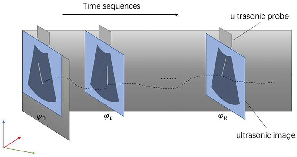
Figure 1: Pipeline of puncture needle’s tip tracking based on ultrasound images
2.1 Motion Modeling of Puncture Needle Tip
The robotic arm drives the puncture needle into the soft-tissue phantom
Under this system, the coordinate value of needle’s tip is defined as Eq. (1):
where
Its velocity is the derivative of position vs. time
where
Let
where
2.2 Principle of Ultrasonic Servo
The compensator is used to move the ultrasound probe along the X-axis according to the needle tip velocity. The estimated error of
where
The calculated pose of the needle’s tip is defined as
By using a gain controller to change the speed of the ultrasonic probe, the ultrasonic probe is forced to move towards the needle’s tip and minimize
2.3 Model of Servo-Motor-Driven Robotic Arm
The motion model of servo-motor-driven manipulator can be simplified as a damper and a mass model as shown in Fig. 2, and the mechanical equation is defined as Eq. (5):
where
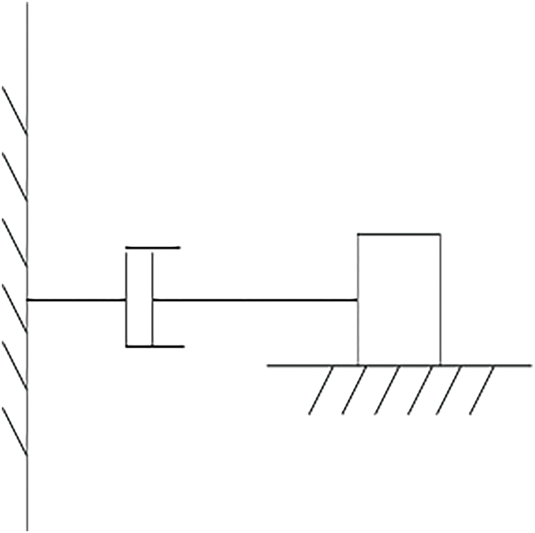
Figure 2: Model of ultrasonic servo drive
While controller synthesis adopts a lumped mass–damper representation, the ensuing phantom experiments employ the physical robot, so friction, backlash, and compliance are implicitly contained in all experiments’ reports.
2.4 State Equations of the Extended Kalman Filter
Since the 2D ultrasound only detects targets within the 2D scanning plane and has large measurement noise, in this work, the EKF is used to estimate the 3D position and velocity of the tip from the noisy and intermittent measurements provided by the 2D ultrasound system. Two different forms of state vectors are designed for the EKF.
2.4.1 Position and Velocity State Vector
The Position and Velocity (PV) state vector is composed of the 3D position of the needle tip and its velocity components,
The classical Constant Velocity (CV) model is used to construct the state equation for needle tip motion, as shown in Eq. (7):
where
The derivative of Eq. (7) with respect to the state vector x yields the linearized state transition matrix
where
Let z be the 3D measurement of the tip position derived from the ultrasound system. The measurement equation is written as Eq. (9):
where
2.4.2 Position and Relative Velocity State Vector
Due to the use of the classical CV model, the PV state model will inevitably receive a shock when there is an abrupt change in the needle feed speed. To solve this issue, the relative velocity concerning
where
The state equation still uses the CV model defined in Eq. (7). With the Position and Relative Velocity (PRV) state vector defined by Eq. (11), the state transition matrix is defined as in Eq. (12):
where
The measurement equation is consistent with that of the PV case (see Eq. (9)).
All experiments in this study were carried out on a water-bath tissue-mimicking phantom using the actual ultrasound probe, EC63 collaborative robot, and industrial camera, listed in Table 1.
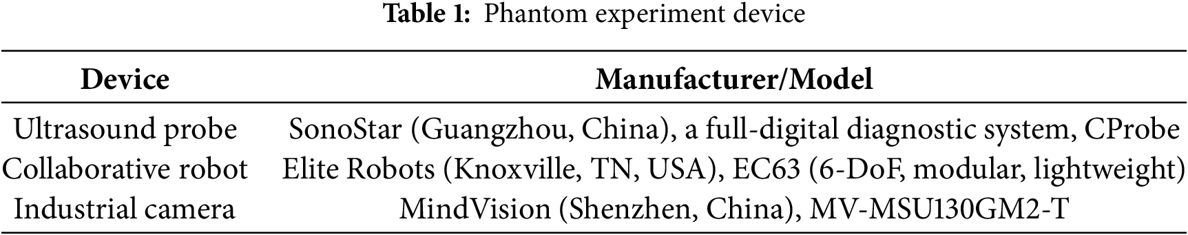
In the experiment, the camera, robotic arm, and industrial camera are all commercial products with clear manufacturers and models. The calibration plates of the ultrasound probe and puncture needle are generated by 3D printing, and each calibration plate is equipped with four optical balls. The actual experimental environment and some components are shown in Fig. 3:
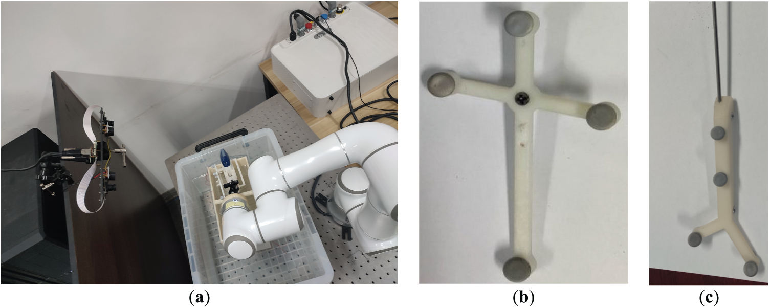
Figure 3: Schematic diagram of the experimental equipment. (a) Experimental scene; (b) Ultrasonic probe optical calibration plate; (c) Puncture needle tip optical calibration plate
3 Controller Design for Controlling Ultrasound Probes
The Kalman filter [31] employed in this study follows the standard two-stage workflow of prediction and correction. The controller calculates the control variable (
As shown in Fig. 4, the
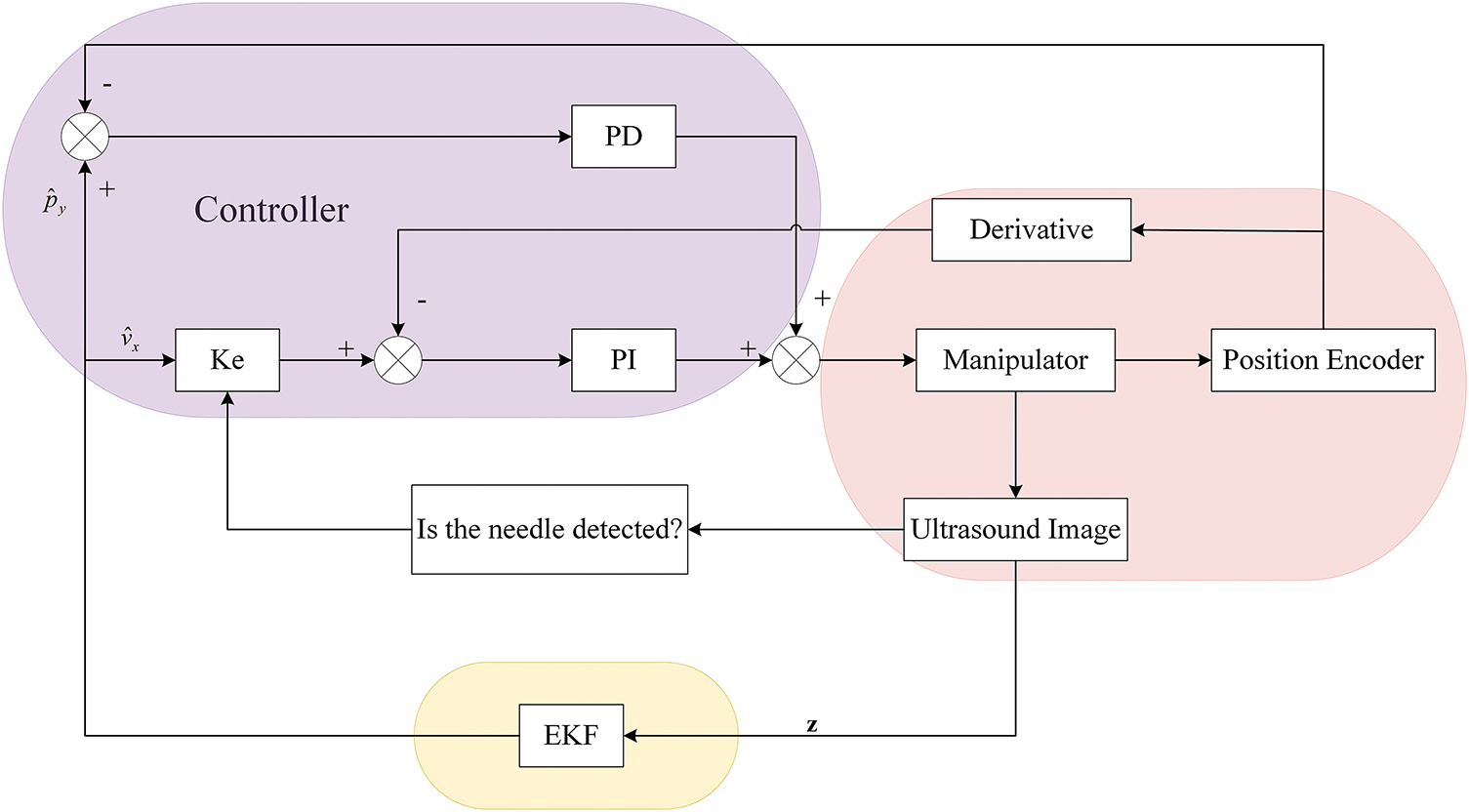
Figure 4: Overall control block diagram for tracking the needle tip using 2D ultrasound images
3.1 Controller in the X-Axis Direction
In the proportional derivative (PD) controller [32], the proportional component reacts proportionally to system deviations. Higher proportional gains accelerate adjustment and reduce errors; however, excessively high gains may compromise system stability, potentially causing instability. The integral component eliminates steady-state errors and enhances error correction, which integrates the speed error over time until the error is eliminated. Once the velocity deviation is zero (the feedback velocity is equal to the reference velocity), the integral component ensures that the controller outputs a constant f to maintain this velocity balance.
As shown in Fig. 5, the reference velocity is obtained by multiplying the X-direction velocity estimate
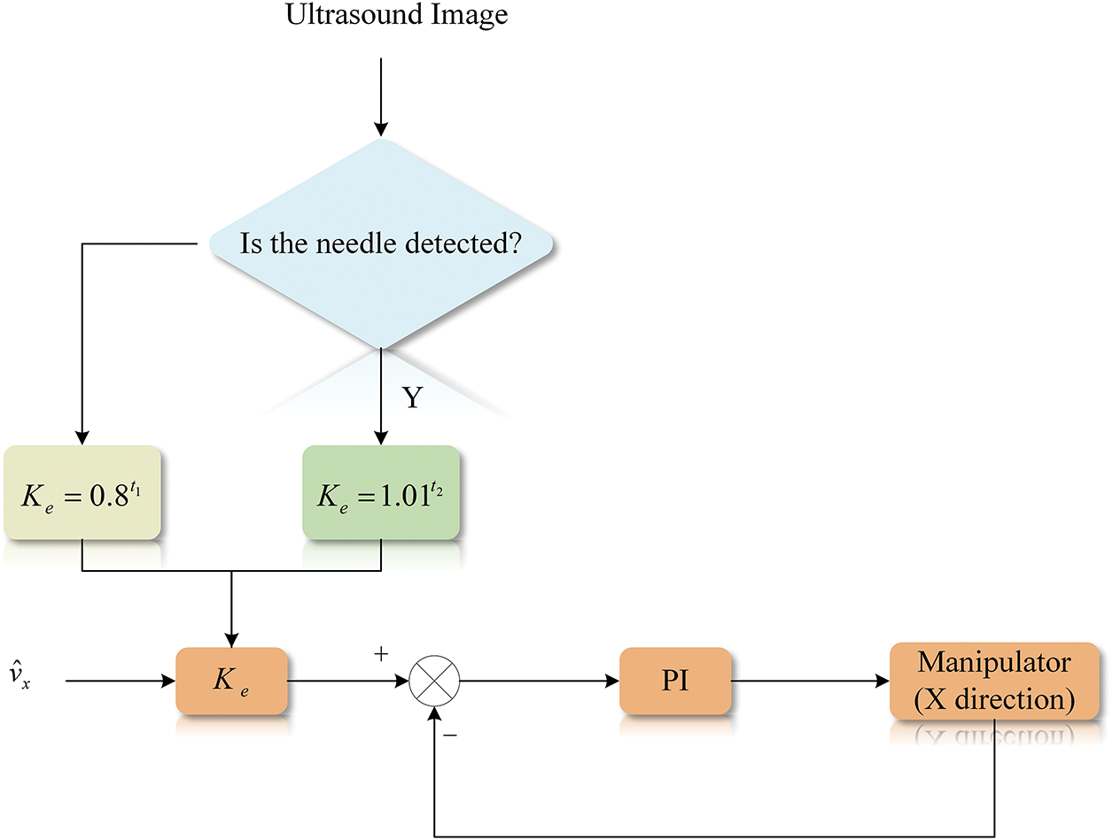
Figure 5: Control flow graph for X-axis direction
To achieve this, a dynamic speed regulation strategy is designed as Eq. (13):
where
The velocity difference at the k-th control cycle is first calculated by Eq. (14):
where
where
Solving Eq. (15) gives the velocity of the ultrasound probe after the
3.2 Controller in the Y-Axis Direction
The standard proportional derivative (PD) controller is used to control the movement of the ultrasound probe along the
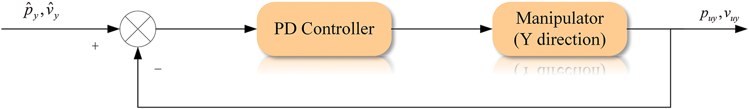
Figure 6: Control flow graph for Y-axis direction
The position difference is first calculated: as Eq. (17):
where
where
The
The proposed servo tracking scheme is validated based on a simulated puncture trajectory. The frame rate (sampling frequency) of the ultrasonic system is set to
The velocities of the puncture needle are planned with the sampling frequency
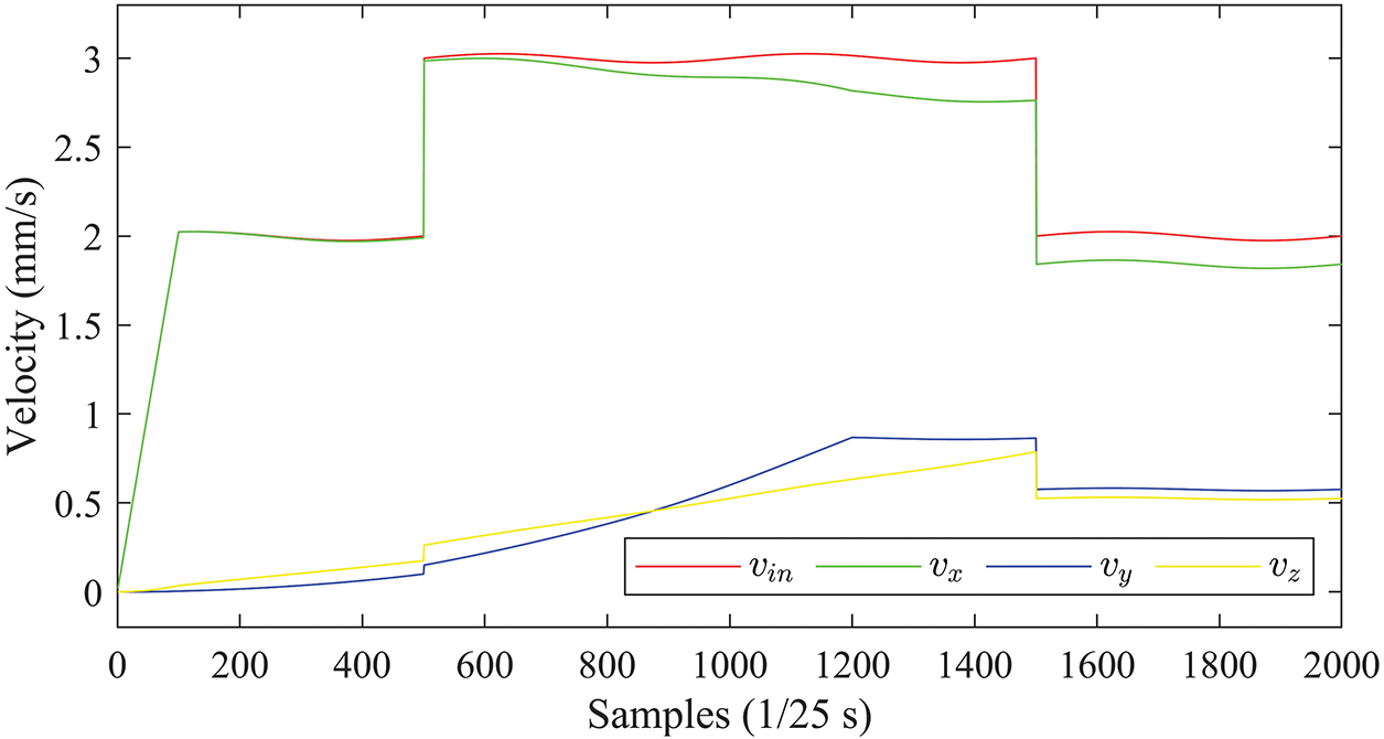
Figure 7: Planned velocity curves of the needle tip
To simulate the dynamic perturbation of the insertion device, a sinusoidal component with an amplitude of 0.025 mm/s and a period of 20 s is superimposed on the above planned velocity profile.
According to Eq. (3), the insertion velocity
In Fig. 7, the velocity components
Without loss of generality, the starting point of the needle trajectory is at the origin of the world coordinate system. The whole trajectory of the needle tip is shown in Fig. 8.
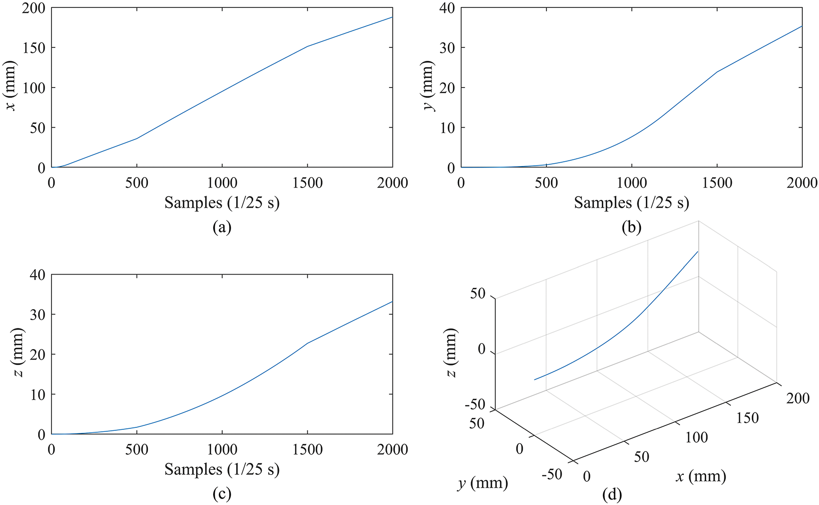
Figure 8: Simulation of needle tip motion. (a–c) are the moving curves of the needle tip in the X, Y, and Z axes, respectively. (d) is the 3D trajectory of the needle tip
From Fig. 8d, it is observed that the 3D trajectory of the tip is smooth and shows a continuous direction change during the puncture, which is consistent with the actual puncture process. In Fig. 8a–c, the motion curves of the tip exhibits dynamics consistent with the insertion speed (
The parameters of the manipulator model are set as follows: the mass m = 150 and the damping coefficient
4.2 Phantom Experiment Based on Position and Velocity (PV)
The covariance matrix of processing noise used in the EKF is set as Eq. (20):
And the covariance matrix of measurement noise is set to Eq. (21):
where the variances in the
The results of needle tip tracking in the
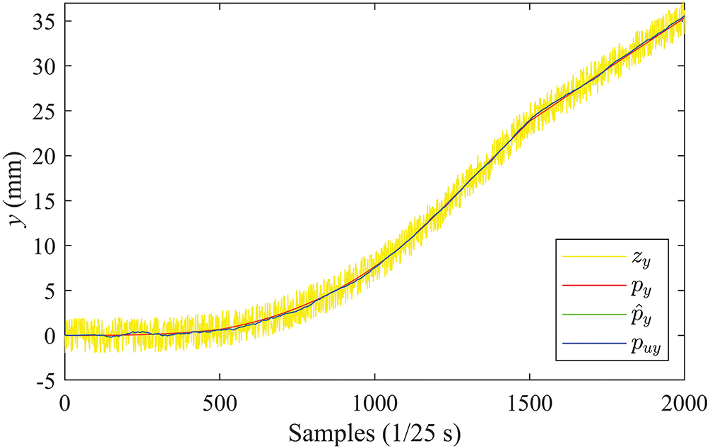
Figure 9: Position curves in the Y-direction (PV)
It can be observed from the figure that the EKF can effectively suppress the noise measurement in ultrasound devices. The estimated
Tracking in the
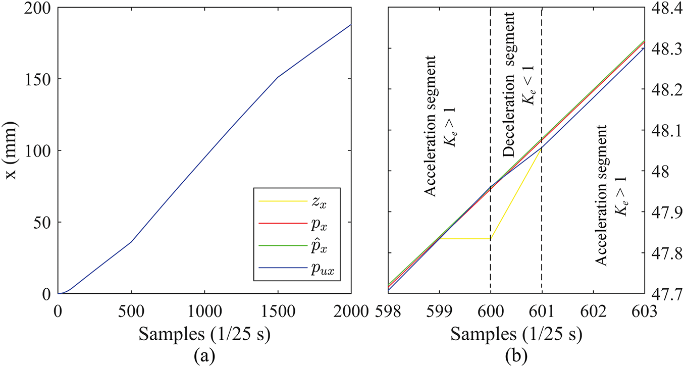
Figure 10: Position curves in the X direction (PV): (a) complete curves, (b) zoomed-in details
The tracking accuracy in the
With this switching of acceleration and deceleration controlled by
Fig. 11 shows the velocity curves in the X and Y directions estimated by the EKF with the PV state vector.
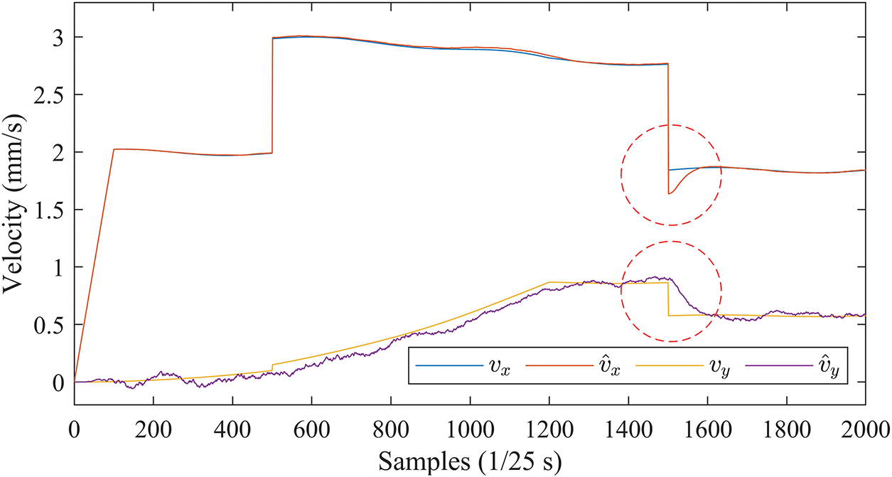
Figure 11: Velocity curves in the X and Y directions estimated by EKF (PV)
The velocity estimates are generally accurate, and only when the insertion speed changes abruptly are there short transitions (marked by red circles) in the estimated curves
Fig. 12 shows the 3D motion trajectories of the needle tip estimated by the EKF with the PV state vector.
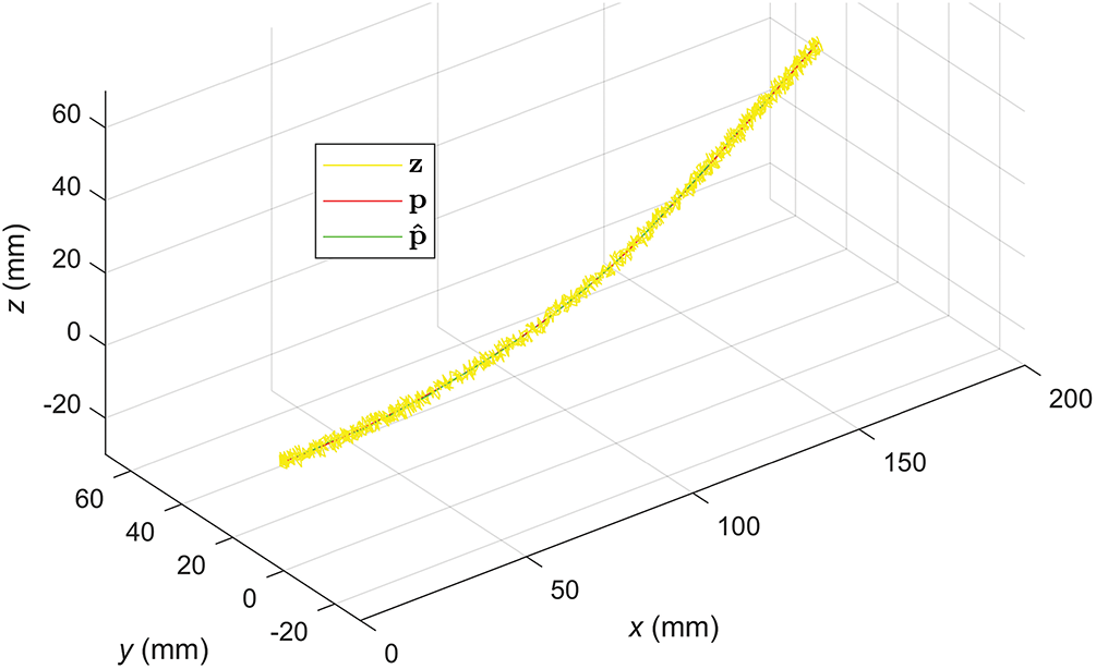
Figure 12: Velocity curves in the X and Y directions estimated by EKF (PV)
Despite the large noise in the measurements (
4.3 Phantom Experiment with PRV State Vector
The covariance matrix of processing noise for the PRV case is set as in Eq. (22):
And the covariance matrix of measurement noise is set to Eq. (23):
The tracking results in the
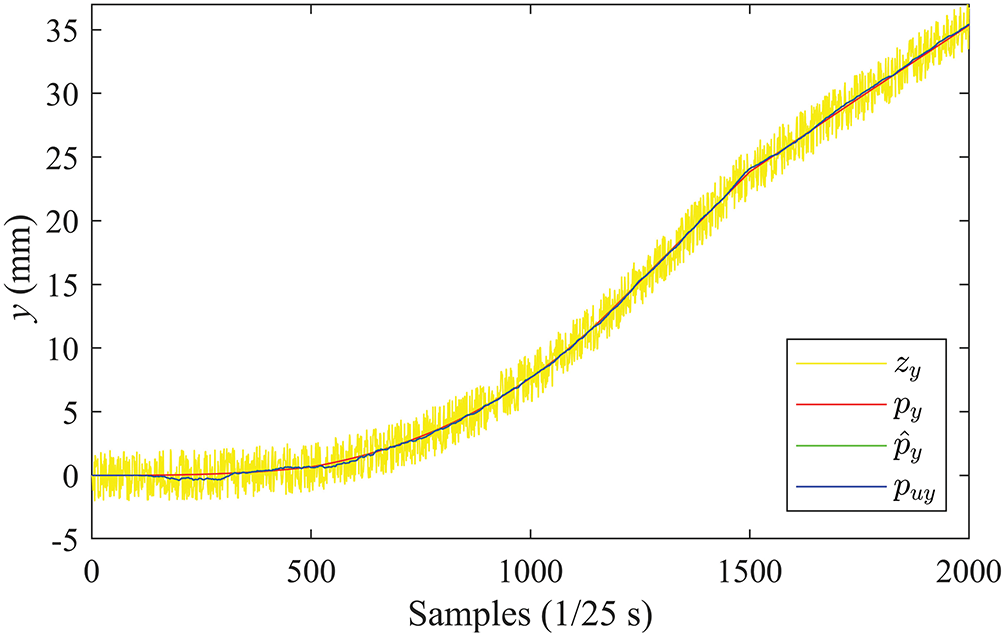
Figure 13: Position curves in the Y direction (PRV)
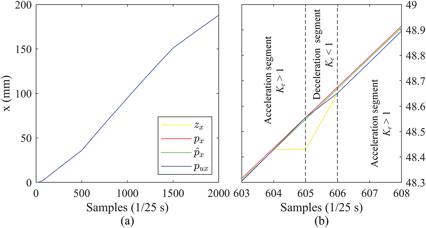
Figure 14: Position curves in the X direction (PRV): (a) complete curves, (b) zoomed-in details
Fig. 15 shows the velocity curves in the X and Y directions estimated by the EKF with the PRV state vector.
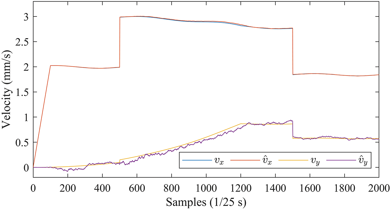
Figure 15: Velocity curves in the X and Y directions estimated by EKF (PRV)
Comparison with Fig. 11 shows that the EKF with PRV can effectively cope with the perturbations caused by sudden changes in insertion speed, with consistently accurate velocity estimates in all directions.
The effectiveness of the EKF with PRV is also demonstrated by the 3D motion trajectories in Fig. 16.
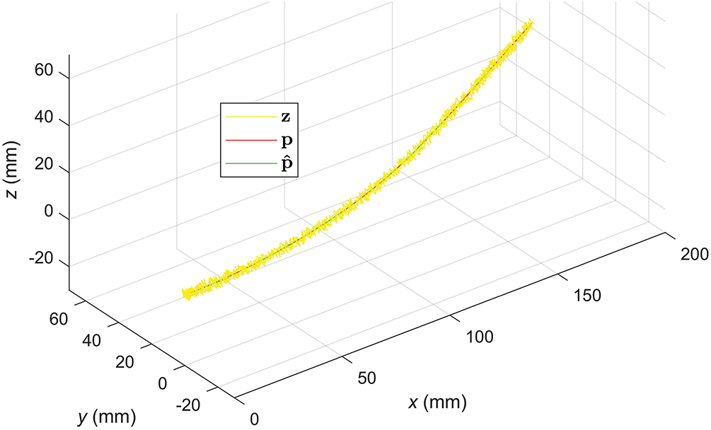
Figure 16: 3D motion trajectories of the needle tip estimated by the EKF (PRV)
The proposed tracking scheme is quantitatively compared with a baseline scheme proposed in [33] (labelled by ICRA since it is published in ICRA 2013), in which
Table 2 shows the average Root Mean Square Errors (RMSE) obtained through 100 repetitions of the experiment using our scheme and the ICRA benchmark with PR and PRV as state vectors, respectively. The first two rows of the table show the estimated errors of the 3D position and
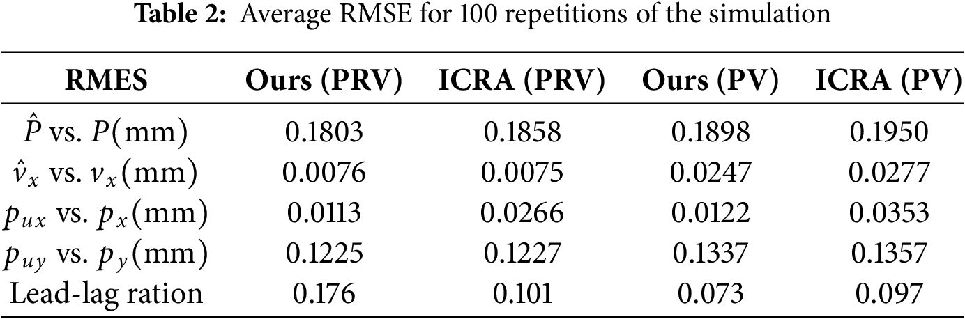
In both PRV and PV configurations, our scheme achieves lower RMSEs than the ICRA benchmark. In particular, the position control accuracy in the X direction (see the row of
The comparisons between PRV and PV are consistent with those between Figs. 11 and 15, and both show that the introduction of relative velocity components in the state vector improves the estimation accuracy of the EKF, and the enhancement is significant, especially in the estimation of velocity in the
This study introduces a needle tip tracking technique utilizing ultrasound images, primarily concentrating on motion-centric approaches for needle localization [34]. This method facilitates servo-driven manipulation of the ultrasound probe contingent on the needle tip’s image-derived information. We propose two distinct approaches: one rooted in position and velocity, and the other in position and relative velocity.
In terms of the final positional tracking accuracy, there is little difference in the performance of the PV and PRV-based EKFs, both of which can accurately localize and track the tip motion, with the PRV slightly outperforming the PV. While in terms of velocity estimation, the PRV is significantly better than the PV, especially when there are step changes in the insertion speed, the PRV performs robustly and can insulate the state estimation from the sudden changes of the insertion speed. Unlike the binary constant velocity control strategy proposed in [33], our strategy dynamically adjusts the reference velocity of the X-direction PI controller according to the number of consecutive ultrasound frames in which the needle is detected or not detected, thus enhancing its adaptability and tracking accuracy. The phantom experiment results demonstrate the effectiveness of this dynamic velocity strategy.
For the six-degree-of-freedom robotic arm featured in this study, the adoption of a conventional Proportional Integral Derivative (PID) control algorithm exhibits the potential to ameliorate the end effector’s positional accuracy within the XY plane. Building upon the conclusions drawn in this article, we independently employ PI and PD controllers along the x-axis and y-axis orientations. This strategic integration aims to mitigate discrepancies in the velocity’s deviation signals following Kalman filtering and the needle tip’s velocity, thereby enhancing overall control precision.
Although this study concentrates on tip-tracking accuracy, it is important to recognize that the phantom experiments inherently incorporate a range of real-world uncertainties. The water-bath setup introduces ultrasound speckle and intensity shading, while the Elite EC63 robot contributes joint friction, minor backlash, and compliance. In addition, slight probe-pressure fluctuations were induced by gentle agitation of the water surface during each run. These factors collectively represent the types of disturbances expected in a clinical environment. In the proposed position and relative velocity Kalman framework, we mitigate the effects of these uncertainties in three ways. First, the noise covariance process is adjusted online by monitoring the innovation sequence; this maintains the filter’s responsiveness without overreacting to transient speckle bursts or instantaneous probe drift. Second, innovations in measurements are discarded if they exceed a preset innovation covariance multiple, thus suppressing the effects of sudden illumination changes. Finally, the controller gains are determined through a series of benchtop experiments that vary the insertion speed and probe trajectory. The consistent tracking performance in these experiments shows that modest parameter changes do not destabilize the closed-loop system.
While our motion-centered, position-and-relative velocity Kalman framework provides accurate needle tip tracking with modest computational demands, we acknowledge that the current study has significant limitations. All results were obtained on a water bath simulated tissue phantom. Although this setup exposes the system to realistic mechanical and imaging perturbations, it cannot capture acoustic heterogeneity and physiological motion in vitro or in vivo experiments. Therefore, this study should be viewed as a “theory plus phantom” feasibility test and not a substitute for clinical evidence. This study has not yet been clinically tested, and the safety aspects are still under discussion. Before clinical deployment, the system must meet the following requirements. For the control part of the instrument arm, the probe contact pressure needs to be limited to avoid tissue damage beyond the range. And provide fail-safe protection when the ultrasound image quality degrades or the tracking is lost. The above issues can be solved by additional multi-sensor solutions [35], such as combining ultrasound with electromagnetic tracking, probe-mounted inertial measurement units (IMUs), and wrist force sensing. This approach can not only improve robustness but also provide redundant safety prompts, triggering automatic pause or retraction actions when the threshold is exceeded.
Three-dimensional motion tracking of a flexible puncture needle using a 2D ultrasound system is a challenging task. Conventional closed-loop position control cannot be used due to the limited capability of the 2D ultrasound as a sensor for measuring the position of the needle tip, whose sensing field is a very thin plane. To achieve tip tracking, the servo control system must accurately drive the ultrasound probe to alternate images in front of and behind the tip based on noisy and discontinuous measurements provided by the ultrasound images. The proposed tracking scheme uses EKF to estimate the position and velocity of the tip from noisy and incomplete measurements. Two different forms of state vectors are investigated in the EKF: one based on position and velocity and the other on position and relative velocity. Based on the state estimation of EKF, the PI and PD controllers are used for velocity control in
Subsequent endeavors could incorporate a mechanical arm designed to govern the
Furthermore, the current experimental setup wherein the ultrasonic probe is affixed to move solely along the X-axis direction introduces scenarios where the puncture needle tip’s image might elude detection in the ultrasound image. Prospective work envisions an ultrasound image that continuously tracks the puncture needle tip along the tangent direction of its trajectory, thereby enabling real-time puncture needle tip tracking.
Acknowledgement: Not applicable.
Funding Statement: The research was supported by the Sichuan Science and Technology Program (2023YFSY0026, 2023YFH0004).
Author Contributions: The authors confirm contribution to the paper as follows: Conceptualization, Bo Yang and Hao Quan; methodology, Minyi Tang; software, Shitong Ye; validation, Bo Yang, Jiawei Tian and Shan Liu; formal analysis, Hao Quan; investigation, Shitong Ye; resources, Minyi Tang; data curation, Shan Liu; writing—original draft preparation, Shitong Ye; writing—review and editing, Jiawei Tian; visualization, Jiawei Tian; supervision, Minyi Tang; project administration, Shan Liu; funding acquisition, Bo Yang, Shan Liu and Hao Quan. All authors reviewed the results and approved the final version of the manuscript.
Availability of Data and Materials: Experimentdata and source code are publicly available (https://github.com/Caroline1-W/Tracking-of-Puncture-Needle, accessed on 18 June 2025).
Ethics Approval: Not applicable.
Conflicts of Interest: The authors declare no conflicts of interest to report regarding the present study.
References
1. Chen YW, Hanak BW, Yang TC, Wilson TA, Hsia JM, Walsh HE, et al. Computer-assisted surgery in medical and dental applications. Expert Rev Med Devices. 2021;18(7):669–96. doi:10.1080/17434440.2021.1886075. [Google Scholar] [PubMed] [CrossRef]
2. Chen Y, Xu L, Chen H, Zeng Y, Guo S, Deng J, et al. Two-stage and two-discriminator generative adversarial network for the inpainting of irregularly incomplete iris images. Displays. 2024;82:102626. doi:10.1016/j.displa.2023.102626. [Google Scholar] [CrossRef]
3. Hu W, Jin T, Pan Z, Xu H, Yu L, Chen T, et al. An interpretable ensemble learning model facilitates early risk stratification of ischemic stroke in intensive care unit: development and external validation of ICU-ISPM. Comput Biol Med. 2023;166:107577. doi:10.1016/j.compbiomed.2023.107577. [Google Scholar] [PubMed] [CrossRef]
4. Zhang H, Cai Z, Xiao L, Heidari AA, Chen H, Zhao D, et al. Face image segmentation using boosted grey wolf optimizer. Biomimetics. 2023;8(6):484. doi:10.3390/biomimetics8060484. [Google Scholar] [PubMed] [CrossRef]
5. Graf T, Keul C, Wismeijer D, Güth JF. Time and costs related to computer-assisted versus non-computer-assisted implant planning and surgery. A systematic review. Clin Oral Implants Res. 2021;32(Suppl 21):303–17. doi:10.1111/clr.13862. [Google Scholar] [PubMed] [CrossRef]
6. Li H, Kim D, Yao Q, Ge H, Chung J, Fan J, et al. Activity-based NIR enzyme fluorescent probes for the diagnosis of tumors and image-guided surgery. Angew Chem Int Ed. 2021;60(32):17268–89. doi:10.1002/anie.202009796. [Google Scholar] [PubMed] [CrossRef]
7. Xia J, Chen H, Li Q, Zhou M, Chen L, Cai Z, et al. Ultrasound-based differentiation of malignant and benign thyroid Nodules: an extreme learning machine approach. Comput Methods Programs Biomed. 2017;147(7):37–49. doi:10.1016/j.cmpb.2017.06.005. [Google Scholar] [PubMed] [CrossRef]
8. Avola D, Cinque L, Fagioli A, Foresti G, Mecca A. Ultrasound medical imaging techniques. ACM Comput Surv. 2022;54(3):1–38. doi:10.1145/3447243. [Google Scholar] [CrossRef]
9. Xiao J, Zhang Y, Zhang M, Lan Y, Yan L, Luo Y, et al. Ultrasonography-guided radiofrequency ablation vs. surgery for the treatment of solitary T1bN0M0 papillary thyroid carcinoma: a comparative study. Clin Endocrinol. 2021;94(4):684–91. doi:10.1111/cen.14361. [Google Scholar] [PubMed] [CrossRef]
10. Youk JH, Kim EK, Kim MJ, Lee JY, Oh KK. Missed breast cancers at US-guided core needle biopsy: how to reduce them. Radiographics. 2007;27(1):79–94. doi:10.1148/rg.271065029. [Google Scholar] [PubMed] [CrossRef]
11. Li P, Yang Z, Jiang S. Needle-tissue interactive mechanism and steering control in image-guided robot-assisted minimally invasive surgery: a review. Med Biol Eng Comput. 2018;56(6):931–49. doi:10.1007/s11517-018-1825-0. [Google Scholar] [PubMed] [CrossRef]
12. Fred HL. Drawbacks and limitations of computed tomography: views from a medical educator. Tex Heart Inst J. 2004;31(4):345–8. [Google Scholar] [PubMed]
13. Fischer GS, Iordachita I, Csoma C, Tokuda J, DiMaio SP, Tempany CM, et al. MRI-compatible pneumatic robot for transperineal prostate needle placement. IEEE/ASME Trans Mechatron. 2008;13(3):295–305. doi:10.1109/TMECH.2008.924044. [Google Scholar] [PubMed] [CrossRef]
14. Shulman SG, March DE. Ultrasound-guided breast interventions: accuracy of biopsy techniques and applications in patient management. Semin Ultrasound CT MR. 2006;27(4):298–307. doi:10.1053/j.sult.2006.05.004. [Google Scholar] [PubMed] [CrossRef]
15. Wu YC, Chen DR, Kuo SJ. Personal experience of ultrasound-guided 14-gauge core biopsy of breast tumor. Eur J Surg Oncol. 2006;32(7):715–8. doi:10.1016/j.ejso.2006.04.012. [Google Scholar] [PubMed] [CrossRef]
16. Wu X, Niu Z, Xu Z, Jiang Y, Zhang Y, Meng H, et al. Fetal weight estimation by automated three-dimensional limb volume model in late third trimester compared to two-dimensional model: a cross-sectional prospective observational study. BMC Pregnancy Childbirth. 2021;21(1):365. doi:10.1186/s12884-021-03830-5. [Google Scholar] [PubMed] [CrossRef]
17. Santago P, Gage HD. Statistical models of partial volume effect. IEEE Trans Image Process. 1995;4(11):1531–40. doi:10.1109/83.469934. [Google Scholar] [PubMed] [CrossRef]
18. Kimbowa A, Pieters A, Tadayon P, Arora I, Gulam S, Pinos A, et al. Advancements in needle visualization enhancement and localization methods in ultrasound: a literature review. Art Int Surg. 2024;4(3):149–69. doi:10.20517/ais.2024.20. [Google Scholar] [CrossRef]
19. Zhu M, Salcudean SE. Real-time image-based B-mode ultrasound image simulation of needles using tensor-product interpolation. IEEE Trans Med Imag. 2011;30(7):1391–400. doi:10.1109/TMI.2011.2121091. [Google Scholar] [PubMed] [CrossRef]
20. Chatelain P, Krupa A, Marchal M. Real-time needle detection and tracking using a visually servoed 3D ultrasound probe. In: Proceedings of the 2013 IEEE International Conference on Robotics and Automation; 2013 May 6–10; Karlsruhe, Germany. doi:10.1109/ICRA.2013.6630795. [Google Scholar] [CrossRef]
21. Zettinig O, Fuerst B, Kojcev R, Esposito M, Salehi M, Wein W, et al. Toward real-time 3D ultrasound registration-based visual servoing for interventional navigation. In: Proceedings of the 2016 IEEE International Conference on Robotics and Automation (ICRA); 2016 May 16–21; Stockholm, Sweden. doi:10.1109/ICRA.2016.7487226. [Google Scholar] [CrossRef]
22. Kallem V, Cowan NJ. Image-guided control of flexible bevel-tip needles. In: Proceedings of the 2007 IEEE International Conference on Robotics and Automation; 2007 Apr 10–14; Rome, Italy. doi:10.1109/ROBOT.2007.363930. [Google Scholar] [PubMed] [CrossRef]
23. Baker C, Xochicale M, Joubert F, Lin FY, Mathews S, Shakir DI, et al. Real-time ultrasonic tracking of an intraoperative needle tip with integrated fibre-optic hydrophone. In: Proceedings of the 2021 IEEE International Ultrasonics Symposium (IUS); 2021 Sep 11–16; Xi’an, China. doi:10.1109/ius52206.2021.9593381. [Google Scholar] [CrossRef]
24. Mathiassen K, Dall’Alba D, Muradore R, Fiorini P, Elle OJ. Robust real-time needle tracking in 2-D ultrasound images using statistical filtering. IEEE Trans Control Syst Technol. 2017;25(3):966–78. doi:10.1109/tcst.2016.2587733. [Google Scholar] [CrossRef]
25. Agarwal N, Yadav AK, Gupta A, Orlando MF. Real-time needle tip localization in 2D ultrasound images using Kalman filter. In: Proceedings of the 2019 IEEE/ASME International Conference on Advanced Intelligent Mechatronics (AIM); 2019 Jul 8–12; Hong Kong, China. doi:10.1109/aim.2019.8868799. [Google Scholar] [CrossRef]
26. Yan W, Ding Q, Chen J, Liu Y, Cheng SS. Needle tip tracking in 2D ultrasound based on improved compressive tracking and adaptive Kalman filter. IEEE Robot Autom Lett. 2021;6(2):3224–31. doi:10.1109/LRA.2021.3063058. [Google Scholar] [CrossRef]
27. Mathews SJ, Shakir DI, Mosse CA, Xia W, Zhang EZ, Beard PC, et al. Ultrasonic needle tracking with dynamic electronic focusing. Ultrasound Med Biol. 2022;48(3):520–9. doi:10.1016/j.ultrasmedbio.2021.11.008. [Google Scholar] [PubMed] [CrossRef]
28. Che H, Qin J, Chen Y, Ji Z, Yan Y, Yang J, et al. Improving needle tip tracking and detection in ultrasound-based navigation system using deep learning-enabled approach. IEEE J Biomed Health Inform. 2024;28(5):2930–42. doi:10.1109/JBHI.2024.3353343. [Google Scholar] [PubMed] [CrossRef]
29. Hui X, Rajendran P, Ling T, Dai X, Xing L, Pramanik M. Ultrasound-guided needle tracking with deep learning: a novel approach with photoacoustic ground truth. Photoacoustics. 2023;34(9):100575. doi:10.1016/j.pacs.2023.100575. [Google Scholar] [PubMed] [CrossRef]
30. Yan W, Ding Q, Chen J, Yan K, Tang RS, Cheng SS. Learning-based needle tip tracking in 2D ultrasound by fusing visual tracking and motion prediction. Med Image Anal. 2023;88(6):102847. doi:10.1016/j.media.2023.102847. [Google Scholar] [PubMed] [CrossRef]
31. Khodarahmi M, Maihami V. A review on Kalman filter models. Arch Comput Meth Eng. 2023;30(1):727–47. doi:10.1007/s11831-022-09815-7. [Google Scholar] [CrossRef]
32. Garpinger O, Hägglund T, Åström KJ. Performance and robustness trade-offs in PID control. J Process Control. 2014;24(5):568–77. doi:10.1016/j.jprocont.2014.02.020. [Google Scholar] [CrossRef]
33. Vrooijink GJ, Abayazid M, Misra S. Real-time three-dimensional flexible needle tracking using two-dimensional ultrasound. In: Proceedings of the 2013 IEEE International Conference on Robotics and Automation; 2013 May 6–10; Karlsruhe, Germany. [Google Scholar]
34. Beigi P, Salcudean SE, Ng GC, Rohling R. Enhancement of needle visualization and localization in ultrasound. Int J Comput Assist Radiol Surg. 2021;16(1):169–78. doi:10.1007/s11548-020-02227-7. [Google Scholar] [PubMed] [CrossRef]
35. Cheng Z, Koskinopoulou M, Bano S, Stoyanov D, Rajeeth Savarimuthu T, Mattos LS. Sensing technologies for guidance during needle-based interventions. IEEE Trans Instrum Meas. 2024;73(1):4009615. doi:10.1109/TIM.2024.3441017. [Google Scholar] [CrossRef]
Cite This Article
 Copyright © 2025 The Author(s). Published by Tech Science Press.
This work is licensed under a Creative Commons Attribution 4.0 International License , which permits unrestricted use, distribution, and reproduction in any medium, provided the original work is properly cited.
 Downloads
 Citation Tools