
 Submit a Paper
 Propose a Special lssue
 Open Access
ARTICLE
Dynamic Characteristics of Different Pantograph Structures for Heavy-Duty Trucks Considering Road Excitation
1 Faculty of Transportation Engineering, Kunming University of Science and Technology, Kunming, 650500, China
2 Faculty of Mechanical Engineering and Transport Systems, Technische Universität Berlin, Berlin, 10623, Germany
3 Department of Engineering Mechanics, KTH Royal Institute of Technology, Stockholm, 10044, Sweden
4 Electrical Road System Research Center, CRRC Zhuzhou Locomotive Co., Ltd., Zhuzhou, 412001, China
5 Department of Mechanical Engineering, University of Maryland Baltimore County, Baltimore, MD 21250, USA
* Corresponding Author: Weidong Zhu. Email:
Computer Modeling in Engineering & Sciences 2025, 144(2), 1655-1676. https://doi.org/10.32604/cmes.2025.068771
Received 05 June 2025; Accepted 30 July 2025; Issue published 31 August 2025
 View Full Text
 Download PDF
Abstract
The emissions from traditional fossil heavy-duty trucks have become a conspicuous issue worldwide. The electrical road system (ERS) can offer a viable solution for achieving zero CO2 emissions and has high energy efficiency in long-distance road cargo transport. While many kinds of pantograph structures have been developed for the ERS, their corresponding pantograph-catenary dynamic characteristics under different road conditions have not been investigated. This work performs a numerical study on the dynamics of the pantograph-catenary interaction of an ERS considering different pantograph structures. First, a pantograph-catenary-truck-road model is proposed. The reduced catenary model and reduced-plate model transmission method are used to minimize model scale. Three different types of ERS pantograph structures are considered in the model. After validation, the pantograph-catenary dynamics under the influence of truck-road interactions with complex road roughness and different pantographs are studied and compared. The corresponding vibration transmission mechanism is further focused. The results show that the truck-road interaction has a significant effect on the pantograph-catenary interaction, but the pantograph with only one lower and upper arm can isolate the roll vibration motion transmission from the truck to the collector head, which has the best dynamic performance and is suggested for use in the ERS.Keywords
Road freight transport plays an important role in freight transport around the world, and heavy-duty trucks with total weights greater than 12 t [1] hold most of the road freight amount. In China, more than 70% of freight, especially for transporting ore, is handled by heavy-duty trucks. Currently, electric vehicles are widely used to reduce carbon emissions in China and other countries [2]. However, owing to the low energy density and high cost of batteries [1], most heavy-duty trucks still use fossil fuel, which results in significant carbon emissions. To use green energy for powering heavy-duty trucks to reduce carbon emissions, the most likely solution is to collect electricity directly and charge the batteries from the infrastructure while driving.
In railway applications, the pantograph-catenary system is a successful technology for continuous power supply over long distances. There have been significant efforts in introducing the technology for powering heavy-duty trucks in Germany [3] and China [4]. The technology is often referred to as electric road systems (ERS), where the components are shown in Fig. 1. ERS provides electrical power to the truck through the catenary and the pantograph. The truck may also use its own electrical or hybrid drivetrain to generate traction power when it leaves the catenary system. Unlike the one for trains, the pantograph should have two collector heads to connect with the parallel catenary lines and form the current loop. The ERS has been proven to be energy efficient and environmentally friendly, while also being more cost-effective than traditional fossil-fuel trucks [5]. Thus, the freight transportation sector will greatly benefit from the development of an eco-friendly and highly efficient long-distance heavy-duty truck system.
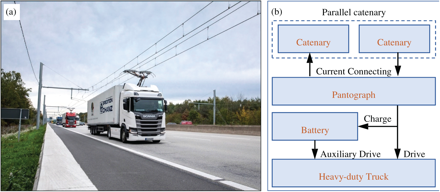
Figure 1: Schematic of the pantograph-catenary-powered heavy-duty truck system: (a) test line and (b) key components of the system
Many prior works have investigated the ERS from different aspects. Most of the work is concentrated on the economy [3,4], reliability [5], and energy parts [6,7], but less work is concentrated on its structure dynamic characteristics. Jerrelind et al. [8] modeled the pantograph of an ERS truck and investigated the dynamics of the pantograph-catenary interaction, where the catenary was modeled based on the Swedish railway catenary systems. However, it only considered the pantograph-catenary system, and the influence of the vehicle-pavement interaction was not considered, which also has a huge influence on the dynamic characteristics of the heavy-duty truck system powered by the ERS. The investigation on the dynamic characteristics of the pantograph-catenary and truck-road interaction system can become the reference for the present ERS dynamic investigation. For example, Bruni et al. [9] summarized the achievements and future research challenges of the pantograph-catenary interaction dynamics, including the modeling and dynamic characteristic analysis method. Antunes et al. [10] developed a new method to investigate the dynamics of pantograph-catenary interaction in curved track. Song et al. [11] optimized the pantograph-catenary system for over 350 km/h based on an experimentally validated pantograph-catenary system model. Cheng et al. [12] even developed a surrogate model of the pantograph-catenary interaction system. Ling et al. [13] investigated the dynamic impact of automated truck platooning on highway bridges based on a truck-road-bridge model. Nassif and Liu [14] developed an analytical model of bridge-road-vehicle dynamic interaction to investigate its dynamic characteristics. Savio et al. [15] further investigated the dynamic load transfer of truck braking to the pavement. Wang et al. [16] studied the driving safety of the vehicle based on driver-vehicle-road interactions.
As mentioned above, the dynamic response of the pantograph-catenary system directly affects the current collection quality and service life of the pantograph-catenary system. Poor pantograph-catenary interaction dynamic behavior can even cause failure of the pantographs and interrupt the normal operation of the entire system, including abnormal wear of the pantograph contact strip and the breakdown of the Direct Current-Direct Current Converter (DC-DC). Note that the dynamic behavior of the truck power supply system is much different from that of the corresponding railway system because of the complex structure of the pantograph and catenary, as shown in Figs. 1 and 2, and the combined influence of the road-vehicle interaction under a rough road surface. In the particular example we consider in this paper, the pantograph-catenary powered heavy-duty truck system in China is mainly used to transport ore, and the dropping of ore on the road can further cause additional roughness on top of existing uneven pavement. However, the dynamic characteristics of the pantograph-catenary system in an ERS under road roughness has not been fully investigated, especially when it comes to the vibration transmission mechanism from the truck to the collector head. Although many kinds of pantograph structures have been developed so far for the pantograph-catenary system of an ERS, their dynamic performance and vibration transmission characteristics have not yet been studied; thus, the structure of the pantograph in an ERS under complex road roughness still needs to be investigated. Therefore, to understand the dynamic characteristics of the ERS’s pantograph-catenary system and choose the best structural design of pantographs, it is necessary to accurately formulate a dynamic model of a pantograph-catenary-truck-road system with different pantograph structures and investigate the dynamic characteristics of the truck pantograph-catenary system.
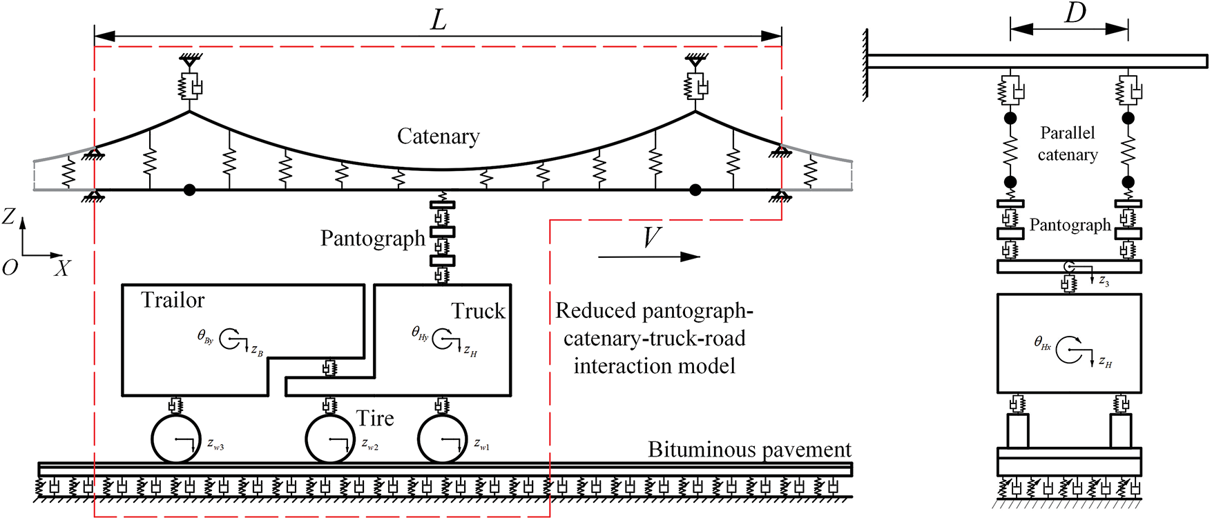
Figure 2: Schematic of the reduced ERS pantograph-catenary-truck-road interaction model
In this work, the dynamic characteristics of the pantograph-catenary interaction in an ERS with different pantograph structures are studied. First, considering the mechanical structure of the ERS, a reduced pantograph-catenary-truck-road interaction model is built. Because the structure of the catenary and truck-pavement system is the same as that of existing systems, the reduced catenary model [17] and reduced-plate model transmission method [18] are used to model the pantograph-catenary and truck-road interaction system, where the arbitrary Lagrange-Euler method [19] is applied in the modeling process to minimize the demand for calculation effort. For comparison, three different ERS pantograph structures are analyzed and modeled as multibody systems, which are combined with the reduced pantograph-catenary interaction model. The parameters of one pantograph are measured, and the other two pantographs are assumed to have the same parameters to minimize the influence of parameters, including the mass, stiffness, and damping. The special road roughness of China’s ore transportation road is also modeled. After model validation through the comparison with the finite element model’s results, the influence of truck-pavement interactions on pantograph-catenary dynamic behavior is investigated first, and then the dynamic behavior of different pantographs under complex road roughness in China’s ore transportation road is studied and compared. Finally, the vibration transmission mechanism of the ERS with different pantograph structures is analyzed, and the pantograph structure with the best dynamic behavior is suggested. This work will provide a basis for choosing the most suitable pantograph in ERS and will be useful for the optimal design of the pantograph-to-road system. The novelty of this work is as follows: 1. The first ERS pantograph-catenary-truck-road interaction model is developed, and three ERS pantograph structures are summarized. 2. The dynamic performance of different pantograph structures in the ERS under complex road roughness is compared. 3. The vibration transmission mechanism of an ERS with different pantograph structures is analyzed, and the best pantograph structure in an ERS is suggested.
The remainder of the paper is organized as follows. The reduced pantograph-catenary-truck-road interaction model with different pantograph structures is formulated in Section 2. The validation of the model is conducted in Section 3, and the dynamic characteristics of the pantograph-catenary interaction system under different pantograph structures are investigated in Section 4. The conclusions are described in Section 5.
2 ph-Catenary-Truck-Road Interaction Model
In this section, a pantograph-catenary-truck-road interaction model and three different types of ERS pantographs are first formulated as shown in Figs. 2 and 3. Note that the parallel catenary doubles the scale of the catenary model and that both the catenary and the road are considered in the model. The vibrations of the catenary and road are also concentrated in a small area around the moving pantograph and truck because of system damping. To reduce the scale of both the catenary and road models and increase the calculation efficiency of the whole pantograph-catenary-truck-road interaction model, on the basis of the theories of the reduced catenary model [17] and the reduced-plate model transmission method [18], the long parallel catenary and road regions are reduced to a small region (red region in Fig. 2) around the moving vehicle and pantograph, and these reduced catenary, road, vehicle and pantograph regions formulate the reduced ERS pantograph-catenary-truck-road interaction model. Details of the modeling process are described in this section. The displacement and rotation of the catenary and road structure are assumed to be small.
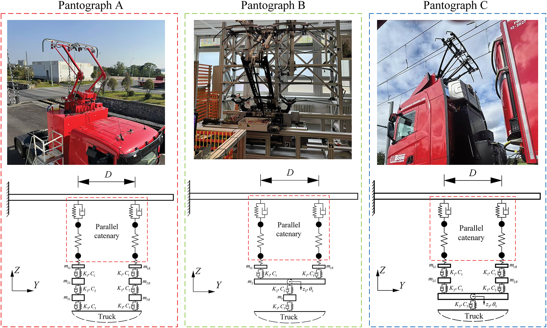
Figure 3: Three different types of ERS pantographs and their dynamic structures
2.1 Modeling of the Reduced ERS Pantograph-Catenary Interaction System
2.1.1 Modeling of the Reduced ERS Catenary System
As shown in Figs. 1 and 2, the structure of a single catenary in the parallel catenary system is the same as that of the simplified catenary system in a traditional railway system, which consists of a contact wire, messenger wire, dropper, catenary suspension, registration arm, and clamp. The only difference between the traditional simplified catenary system and the present ERS catenary system is that it has two parallel subcatenary systems, which hang separately on the crossbeam. It is also found that the vibration of the catenary is concentrated in a small area around the moving pantograph due to the structure damping. Therefore, on the basis of the theory of the reduced catenary model [17], the catenary in a small region around the moving pantograph with a length of L is considered and modeled, which is assumed to include most of the catenary vibration. Its dynamic equations can be expressed as
where M, C, and K are the mass, stiffness, and damping matrices of the dynamic equations with respect to the contact and messenger wires, respectively. QF is the generalized force vector caused by the forces acting on the contact and messenger wire, which includes the pantograph-catenary contact force, dropper force, suspension forces, registration arm forces, and gravity. In the present model, the contact and messenger wires are modeled as Euler beams, the dropper is modeled as a bi-linear spring element, the catenary suspension is modeled as a spring-damping element, and the registration arm is modeled as a constant concentrated mass attached to the contact wire. The subscripts m and c indicate the messenger and contact wires, respectively. The derivation process and the expression of these matrices can be found in [17].
On the basis of the dynamic equation of a single catenary, the dynamic equations of the entire parallel catenary can be further obtained as
where
in which the subscripts L and R indicate the left and right sides of the catenary, respectively. Note that the crossbeam that supports the parallel catenary is stiffer than that of the catenary and that the catenary vibration has little influence on the crossbeam. Thus, the dynamic influence between the parallel catenary can be ignored.
2.1.2 Modeling of the Pantograph
While the structure of the catenary in the ERS is the same as that of the simplified catenary system in a railway and its dynamic equations are obtained on the basis of the existing results from [17], the pantograph structure is completely different from that in a railway and should be carefully modeled to study its dynamic performance. There are three main types of pantograph structures in an ERS, as shown in Fig. 3, which are designed by Siemens Mobility and CRRC Zhuzhou. All of these pantographs have two parallel collector heads to contact the parallel catenary, but the number of upper and lower arms is different. In this work, these three pantographs are named pantographs A, B, and C, and their dynamic equations are derived below.
(a) Pantograph A. The structure of Pantograph A can be considered as two small pantographs combined together. Each small pantograph has one collector head, upper arm, and lower arm. Thus, it can be modeled as two multirigid body systems assembled together. The distance between these two collector heads is D. Each multirigid body system has three lumped masses m1, m2, and m3. K1 and C1 are the stiffness and damping of the collector heads, K2 and C2 are the stiffness and damping of the upper arms, and K3 and C3 are the stiffness and damping of the lower arms, respectively. All of these lumped masses consider only their vertical displacement. On the basis of the Lagrange equation, the dynamic equation of the pantograph is
where
In Eq. (5), qPA = [z1L z2L z3L z1R z2R z3R]T, where z1L and z1R are the vertical displacements of the collector head, z2L and z2R are the vertical displacements of the upper arm at the left and right sides, and z3L and z3R are the vertical displacements of the lower arm, respectively. The QPA is the generalized force vector caused by the pantograph-catenary contact force, uplift force, gravity force, aerodynamics, and car body vibration.
(b) Pantograph B. The structure of Pantograph B has only one upper arm and one lower arm, and the two collector heads are both supported by the upper arm. Pantograph B is also modeled as a multirigid body system with three lumped masses m1L, m1R, and m3 and one rigid body with mass m2 and second moment Ix2. This rigid body is the upper arm. On the basis of the Lagrange equation, the dynamic equation of the pantograph is
where
In Eq. (9), qPB = [z1L z1R θ2 z2 z3]T, where z1L and z1R are the vertical displacements of the collector head and z2 and z3 are the vertical displacements of the upper arm and lower arm, respectively. θ2 is the roll motion of the upper arm. In Eqs. (11) and (12), K4 and C4 are the stiffness and damping, respectively, of the upper arm in the roll direction. The QPB is the generalized force vector caused by the pantograph-catenary contact force, uplift force, gravity force, aerodynamics, and car body vibration.
(c) Pantograph C. The structure of Pantograph C has two collector heads; each collector head is supported by one upper arm, and these two upper arms are supported by one lower arm. Pantograph C can be further modeled as a multirigid body system with four lumped masses m1L, m2L, m1R, and m2R and one rigid body with mass m3 and second moment Ix3. m1L and m1R are the pantograph heads at the left and right sides, and m2L and m2R are the corresponding upper arms. m3 is the lower arm with both vertical and yaw motion considered. K1 and C1 are the stiffness and damping of the collector heads, respectively, and K2 and C2 are the stiffness and damping of the upper arms, respectively. On the basis of the Lagrange equation, the dynamic equation of the pantograph is
where
in which lx is the equivalent distance between the center of the lower arm and the connection point of the upper arm. In Eq. (13), qPC = [z1L z2L z1R z2R z3 θx3]T, where z1L and z1R are the vertical displacements of the collector head, z2L and z2R are the vertical displacements of the upper arm at the left and right sides, respectively, and z3 is the vertical displacement of the lower arm. θx3 is the rotation angle of the lower arm. The QPC is the generalized force vector caused by the pantograph-catenary contact force, uplift force, gravity force, aerodynamics, and car body vibration.
2.1.3 Reduced ERS Pantograph-Catenary Interaction System
On the basis of the dynamic equations of the catenary system and pantograph, the dynamic equations of the reduced ERS pantograph-catenary interaction system can be obtained as
The pantograph-catenary contact force is calculated via the penalty method, and its calculation equation is shown in [20]. The contact stiffness at the left and right collector heads are both chosen as 50,000 N/m, and three different pantographs can be considered in Eq. (17).
2.2 Modeling of the Reduced Vehicle-Pavement Interaction System
After the modeling of the pantograph-catenary interaction system, the vehicle-pavement interaction system is modeled. In the ERS, the vehicle is a heavy-duty truck, which is mainly a semitrailer truck in both Germany and China. Therefore, on the basis of the structure of the semitrailer truck, it is also modeled as a multirigid body system with two rigid bodies and six lumped masses, which correspond to the car head, car body, and tire. The pavement is considered asphalt pavement and is modeled as a double-layer Kirchhoff-Love plate on the nonlinear Winkler foundation. On the basis of the reduced-plate model transmission method [18], the long pavement is also reduced, and the reduced pavement model and vehicle model formulate a reduced vehicle-pavement interaction system. The dynamic equations of the vehicle-pavement interaction system are
where the subscripts V and R indicate the truck and road, respectively. A detailed expression of the matrices of the truck can be found in Appendix A, and the expression of the matrices of the reduced pavement can be found in [18]. QV and QR are the generalized force vectors of the vehicle and pavement, which are caused by the tire-pavement contact forces, gravity, and foundation forces.
2.3 Modeling of the Reduced ERS Pantograph-Catenary-Vehicle-Pavement Interaction System
On the basis of the dynamic equations of the reduced pantograph-catenary and vehicle-pavement interaction model, the entire reduced ERS pantograph-catenary-vehicle-pavement interaction model can be finally formulated. Note that the mass of the vehicle is much greater than that of the pantograph and that the pantograph-catenary interaction force is very small compared with the tire-pavement interaction force. Thus, the influence of the pantograph-catenary interaction on the vehicle-pavement interaction is not included, and only the influence of the vehicle-pavement interaction on the pantograph-catenary interaction is considered. This influence is considered by calculating the coupled force between the vehicle and the pantograph.
In pantograph A, this coupled force is calculated by
where dPZL and dPZR are the vertical displacements of the truck car head at the location of the left and right small pantograph, which is combined by both the vertical displacement and roll motion of the car head.
For pantographs B and C, this coupled force is calculated by
where dPZ is the vertical displacement of the car head at pantograph locations and θPZ is the roll angle of the car head at the pantograph location. K5 and C5 are the stiffness and damping, respectively, of the lower arm in the roll direction.
In the presented model, Eq. (18) is calculated first; then, the calculation results of the car head vibration are used in the calculation process of Eq. (17) through Eqs. (19)–(22) under different pantographs. The present model is achieved via the commercial software MATLAB 2022a, and a computer with i7-14700k CPU and 64 GB memory is used for simulation.
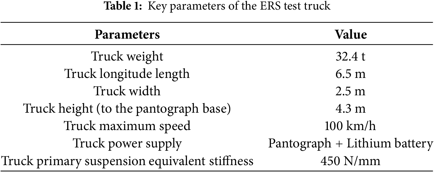
After the formulation of the reduced ERS pantograph-catenary-vehicle-pavement interaction system, it is further validated to ensure its accuracy. Note that while the reduced catenary model has been validated by the EN50318:2018 standard in [17], the present pantograph-catenary interaction system is different from those described in the EN50318:2018 standard, and there is no ERS pantograph-catenary system’s validation standard at present; thus, it is validated by finite element method (FEM) models. The ERS test line built by the CRRC is chosen, and both the commercial software ANSYS and the present model are used to model the pantograph-catenary system of this line. The ERS test line’s catenary system and truck’s key parameters are shown in Fig. 4 and Table 1. The pantograph A is used in this line. Note that the pantograph parameters are not listed here due to confidential reasons.
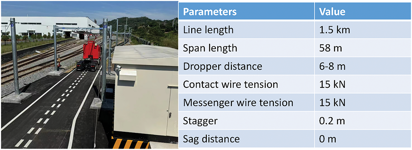
Figure 4: Key parameters of the ERS test line in the CRRC
In the model, on the basis of the pre-analysis method [17], the length of the reduced catenary model L is chosen as 174 m (3 spans), and the length of the reduced pavement model is selected as 36 m. The number of modes used in the catenary model is 120, and the number of modes used in the pavement model at the x and y sides is 36 and 6, respectively. In the ANSYS model, the BEAM 4 element is used to model the contact and messenger wire, and the LINK 8 element is used to model the dropper. The MASS 21 element is used to model the registration arm. The detailed modeling process of the pantograph-catenary model is the same as that shown in [17], which is validated by the EN50318:2018 standard. In the present FEM model, the length of the catenary is considered to be 1000 m, and the number of elements used in the catenary and pavement models is 2000 and 1500, respectively. The truck velocity is chosen as 100 km/h, which is the maximum operation speed of the present test line. In the validation process, the influence of truck-road interaction is not considered, and the truck-road interaction model is not validated. This is because the pantograph-catenary system is concentrated, and the truck-road interaction model was validated in [18]. The road roughness will be further considered and discussed in the next section.
The traditional pantograph-catenary contact force is chosen to validate the present model, which is the key characteristic of the pantograph-catenary system in an ERS, where the contact forces at both sides of the pantograph are chosen and are presented in Fig. 5. The figure shows that the pantograph-catenary contact force results from the presented model are in good agreement with those from ANSYS, where the maximum relative difference is no more than 1.3%. On the basis of these results, the accuracy of the present model can be validated. In the present study, only the simulation results are chosen to validate the presented model. This is caused by the fact that the measurement data of the present test line are not obtained right now.
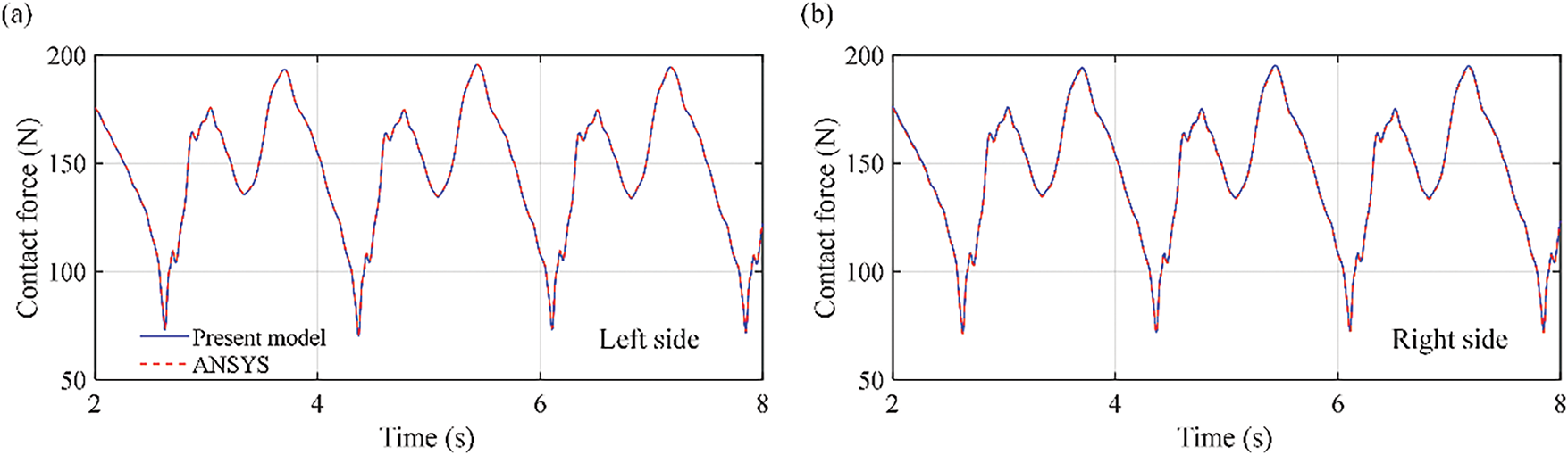
Figure 5: Time histories of the pantograph-catenary contact force at different sides of the pantograph: (a) left side and (b) right side
The influence of stiffness K1L and damping C1L in pantograph A on the relative differences between the results from the present model and the FEM model are shown in Fig. 6, where corresponds to the validation case in the present manuscript in Section 3. It can be seen from Fig. 6 that both K1L and C1L have obvious influence on the dynamic responses of the ERS pantograph-catenary system, and the stiffness has a higher influence than that of damping. When K1L increases from 5000 to 45,000 N/m, the relative difference decreases from 98.5% to 4.5%. But when C1L increases from 4 to 48 N·s/m, the relative difference only decreases from 27.6% to 4.6%. Therefore, the parameters of the pantograph can influence the dynamic characteristics of the ERS pantograph-catenary system.
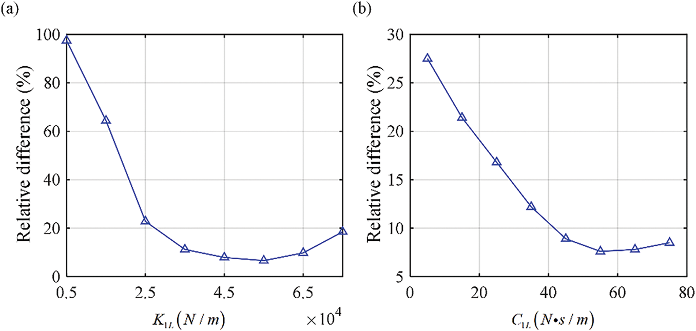
Figure 6: Influence of pantograph parameters on the relative difference between the results from FEM and present model: (a) K1L and (b) C1L
4.1 Influence of Truck-Pavement Interaction on Pantograph-Catenary Interaction
As mentioned above, the dynamic response of the truck-pavement interaction is greater than that of the traditional train-track interaction and can significantly influence the pantograph-catenary interaction, which further increases the complexity of the pantograph-catenary system’s dynamic characteristics. Therefore, this study focused on the present investigation. On the basis of the presented reduced ERS pantograph-catenary-vehicle-pavement interaction model, the dynamic characteristics of the pantograph-catenary interaction system under the truck-pavement interaction are investigated. The abovementioned ERS test line is chosen, and the pantograph equivalent parameters of pantograph A are measured, where m1L = m1R = 2.0 kg, m2L = m2R = 4.1 kg, m3L = m3R = 5.4 kg, K1 = 11,200 N/m, C1 = 10 N·s/m, K2 = 10,040 N/m, C2 = 0 N·s/m, K3 = 13,200 N/m, and C3 = 80 N·s/m. The parameters of the other two pantographs are also chosen to be equal to those of pantograph A to focus on the influence of pantograph structures, and the moments of inertia of the upper arm and lower arm in pantographs B and C are 1.26 and 2.23 kg·m2, respectively. The truck is chosen on the basis of the CRRC’s ERS semitrailer truck, where the car head and car body mass are 10 and 40 t, respectively. Other parameters of the truck are currently confidential. The ground equivalent stiffness is
The pantograph-catenary contact forces at the left and right collector heads of the pantograph with and without truck-pavement interaction influences are first calculated and compared. The time histories of the pantograph-catenary contact force at the left and right collector heads of the pantograph and their corresponding frequency spectra with truck influence are shown in Fig. 7. The truck velocity is chosen as 100 km/h. Fig. 7 shows that truck-pavement interactions have a significant influence on pantograph-catenary interactions. When the influence of truck-pavement interactions is considered, the variation in the contact forces with respect to different pantographs obviously increases, and the contact forces at the left and right sides of the collector head become different. In pantograph A, the variation range changes from [72.2, 189.4 N] to [51.4, 199.6 N], which means that the dynamic behavior of the pantograph-catenary interaction becomes more drastic. The variation range of the contact force in pantograph B also changes to [48.4, 164.3 N], and the variation range in pantograph C changes from [52.6, 175.4 N] to [50.5, 184.7 N]. The maximum absolute difference between the contact forces on the left and right sides in pantographs A and C is 16.2 and 7.8 N, but it remains at 0 N in pantograph B. On the basis of these results, the truck-pavement interaction not only extends the variation range of the contact force but also causes the difference between the contact forces at the left and right sides of the collector heads. In addition, based on Fig. 7c,d, additional peaks of the frequency spectra are shown mainly at 0.31, 0.45, and 0.68 Hz when the truck-pavement interaction influence is considered, which means that the influence of truck-pavement interactions on pantograph-catenary dynamics in the ERS focuses on the low-frequency domain at 0.3–0.7 Hz.
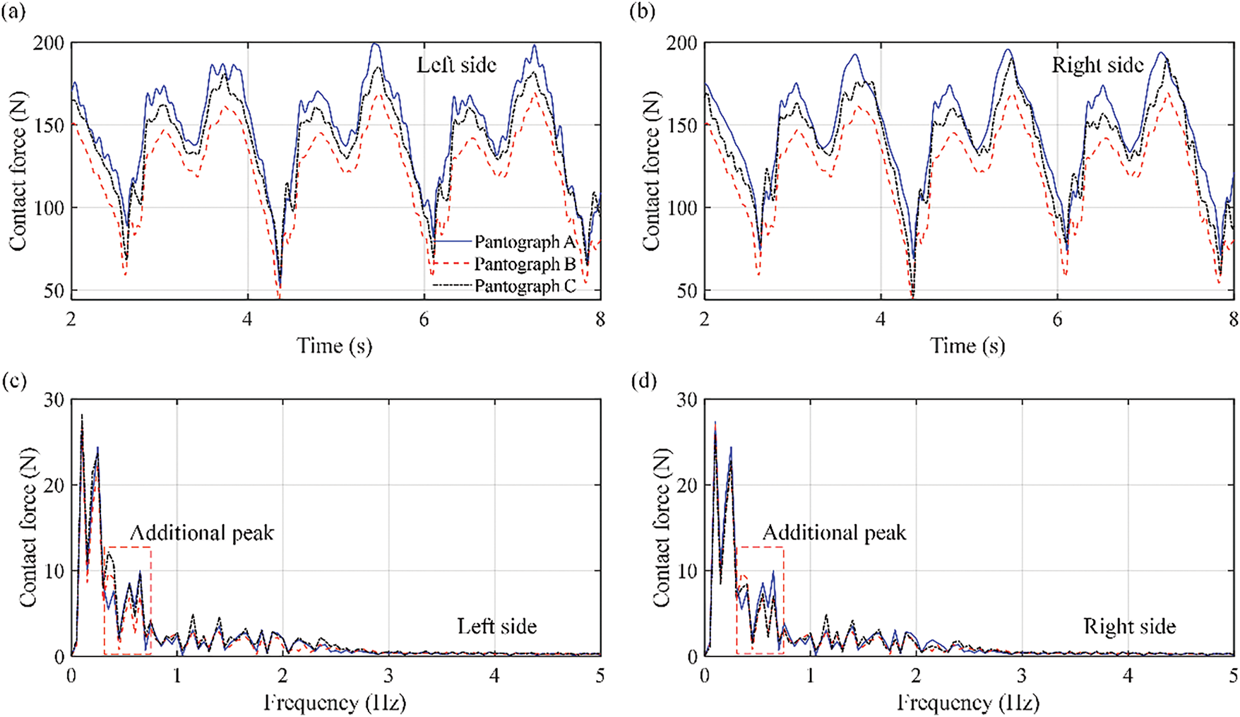
Figure 7: Time histories and frequency spectra of the pantograph-catenary contact force at the left and right collector heads under the influence of truck-pavement interactions at different pantographs: (a) contact force at the left collector head; (b) contact force at the right collector head; (c) frequency spectra at the left collector head; and (d) frequency spectra at the right collector head
The influence of truck-pavement interactions on pantograph-catenary interaction dynamics in ERSs with different road roughness levels is then studied. Four road roughness levels, namely, very good, good, bad, and very bad, are chosen, and the vehicle velocity is chosen as 100 km/h. The minimum pantograph-catenary contact force and the absolute difference between the contact forces at the left and right sides of the pantograph are shown in Fig. 8, and a summary table comparing the main characteristics and performance outcomes of the three pantograph types is shown in Table 2. Fig. 8 and Table 2 show that the road roughness directly influences the dynamic behavior of the pantograph-catenary. When the road roughness increases from very good to very bad, the minimum contact force of pantograph A decreases from 48.9 to 0 N, and it decreases from 53.3 to 0 N at pantograph C. The pantograph-catenary contact forces only decrease from 52.8 to 15.4 N at pantograph B. This means that the very bad road roughness can cause contact loss at pantographs A and C, but it can still maintain relatively good dynamic performance at pantograph B. Furthermore, with the decrease in road roughness level, the absolute difference in the contact force between the left and right sides of the collector heads in pantograph A increases from 1.2 to 38.5 N, and it also increases from 0.8 to 18.4 N at pantograph C. However, it remains smaller than 0.1 N at pantograph B. This further shows that the influence of the truck-pavement interaction on the pantograph-catenary interaction dynamics includes the roll motion of the car head, and it causes the difference between the contact force at the left and right sides and worsens the dynamic behavior of pantographs A and C. However, the structure of Pantograph B can defend against this influence and maintain relatively good dynamic performance.
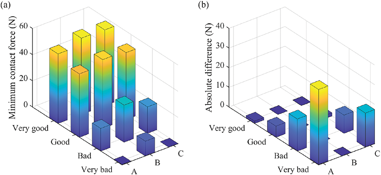
Figure 8: Minimum pantograph-catenary contact force and absolute difference between the contact forces at the left and right sides with respect to different road velocities: (a) minimum contact force and (b) absolute difference
4.2 Comparison of the Dynamic Behavior of Different Pantograph Structures in the ERS of China
The above investigation results indicate that the truck-pavement interaction has an obvious influence on the pantograph-catenary interaction. Moreover, pantograph B has better dynamic performance than the other two pantographs with poor road roughness, where the minimum contact force is greater than that of the other pantographs, and the absolute difference in the pantograph-catenary contact force between the left and right side collector heads is nearly zero. This means that there is no contact loss and that the working performance (like the wear of the contact strip) of the pantograph left and right collector heads is close, which increases the service life of the pantograph and decreases the maintenance cost. To better understand this phenomenon and compare the dynamic behavior of these three pantograph structures, a more complicated road roughness is considered, and the dynamic behavior of these pantograph structures under complicated road roughness is investigated.
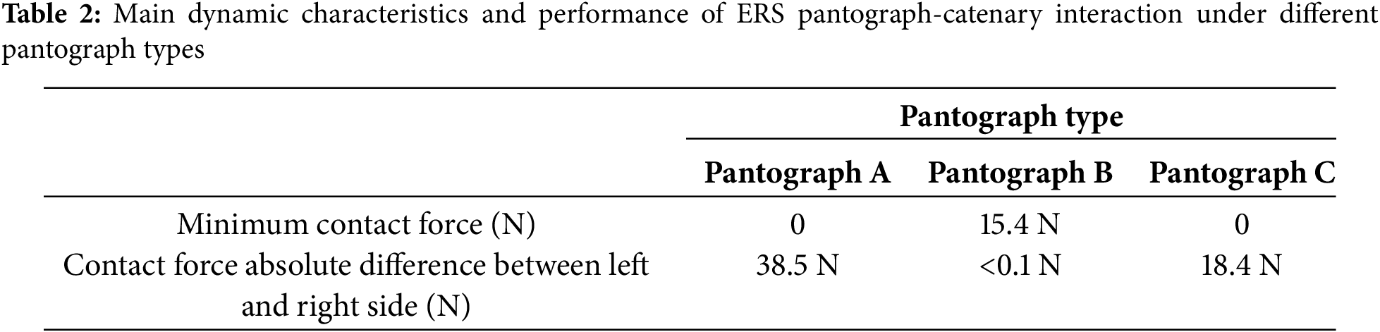
First, the complex road roughness of China’s ore transportation road is modeled. As mentioned above, the ore often drops on the road because there is no cover on the carriage, which causes additional roughness, as shown in Fig. 9. These dropped ore usually drop at one side of the truck and leave a long distance behind, which means that it influences only one side of the truck wheel and causes roll motion of the truck. Let the average height of the ore be h and assume that the dropped ore has the same height at a long distance; the road roughness r(x) with the dropped ore can be expressed as
where r0(x) is the original road roughness obtained from the traditional roughness power spectrum. r(x) is further added to the tire-pavement interaction force calculation equation [23].
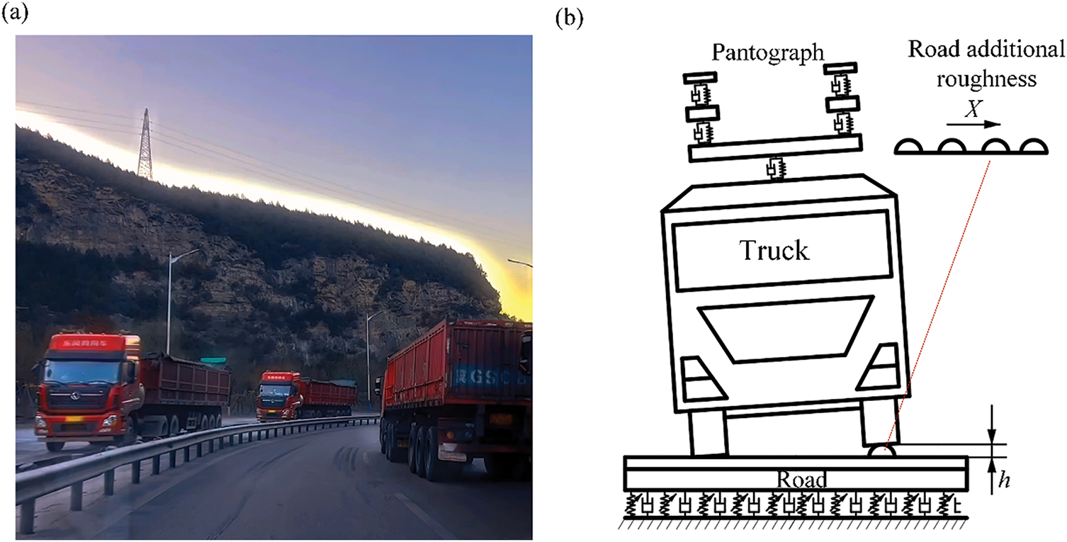
Figure 9: Schematic of the additional roughness of ore transportation roads in China: (a) ore transportation road in China and (b) additional roughness of the road
On the basis of the same pantograph-catenary-truck-pavement interaction system described in Section 4.1, the influence of complex road roughness on the dynamic performance of different pantographs is investigated. The pantograph-catenary contact force under different h values is calculated first, where the original road roughness is chosen as good, which can be considered the newly built road. The time histories of the pantograph-catenary contact forces at the left and right sides of the collector head with respect to different h values and pantographs are shown in Fig. 10, where h is chosen from 10, 20, and 100 mm. Fig. 10 shows that Pantograph B has better dynamic performance than the other two pantographs. With increasing h, the contact force at pantograph A becomes much more severe on the left side, and it directly decreases to zero at 0.1 s. However, the contact force on the right side decreases than that on the left side because of the additional roughness on the left side. This directly causes a very large difference in the contact force between the left and right sides, which can reach a maximum of 98.4 N. This means that Pantograph A cannot defend against the roll motion of the truck and is not suitable for this purpose. Pantograph C is also influenced by the roll motion of the truck, but it can defend it to some extent. While the minimum contact force is also decreased to zero, it remains at only 0.01 s, and the maximum difference in the contact force is only 24.2 N. Note that the minimum contact force is shown on the right side, which is caused by the rotation of the lower arm. Pantograph B completely defends the roll motion, where the maximum difference in the contact force is no more than 0.001 N. The minimum contact force is also 10.2 N even with h = 100 mm. This means that pantograph B also has better dynamic performance in the pantograph-catenary interaction system even under more complex road conditions.
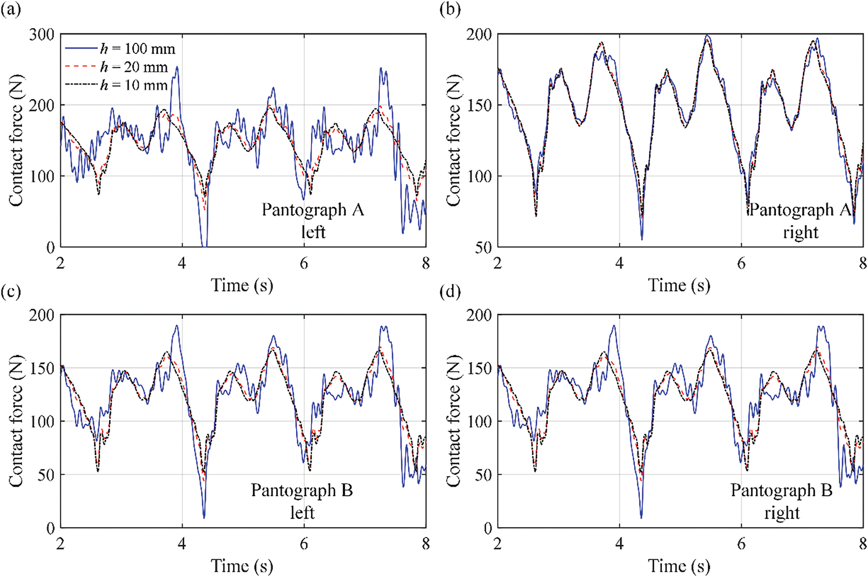
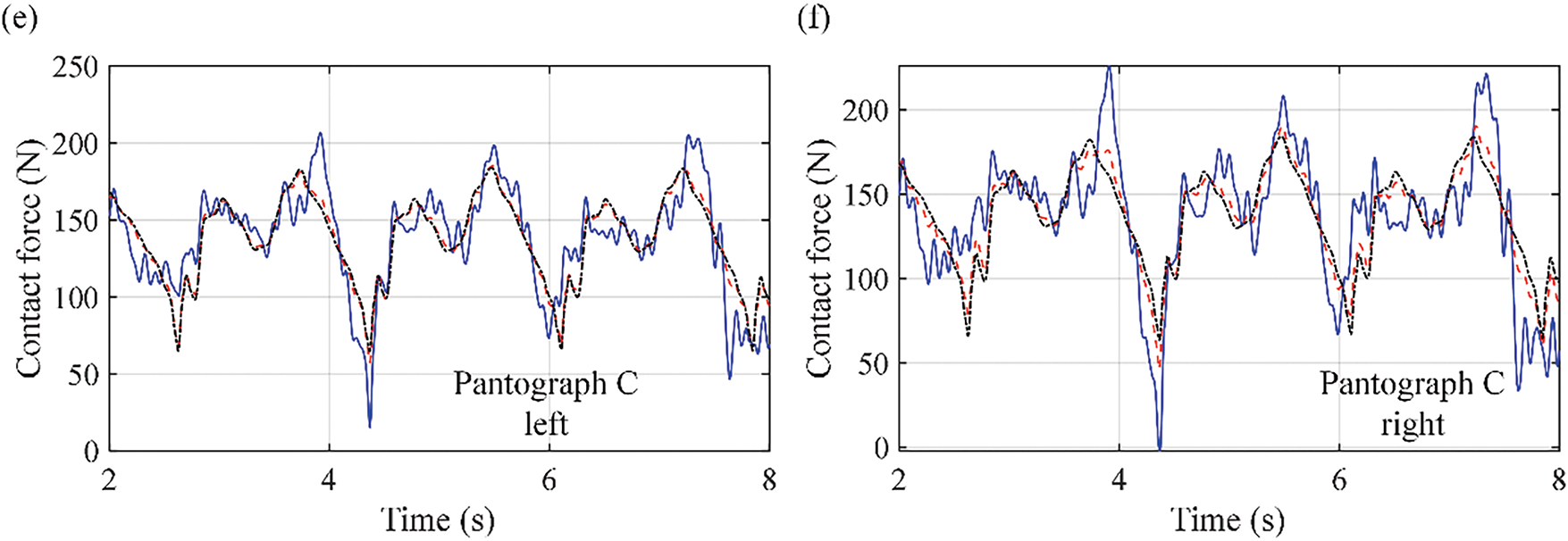
Figure 10: Time histories of the pantograph-catenary contact force at the left and right collector heads with different h at different pantographs: (a) pantograph A left; (b) pantograph A right; (c) pantograph B left; (d) pantograph B right; (e) pantograph C left; and (f) pantograph C right
4.3 Study on the Vibration Transmission Mechanism of Different Pantograph Structures
On the basis of the above investigation results, different pantograph structures have different dynamic performances in the ERS system, and Pantograph B has a better dynamic performance than the other two pantographs, even for complex road roughness. However, the reason why this happens is not drawn from these results. Therefore, to better understand the dynamic characteristics of the pantograph-catenary system in an ERS and choose the best pantograph structure, the vibration transmission mechanisms of different pantograph structures are analyzed.
As shown in Fig. 10, the complex roughness of the road can cause obvious roll vibration of the truck, and it can further combine with the vertical vibration and transmit to the collector head, which causes contact loss and a difference between the contact forces at the left and right collector heads. On the basis of the above pantograph-catenary-truck-road interaction system, the frequency spectra of the pantograph-catenary contact force at the left and right sides are used to study the vibration transmission mechanism, where the results from only the pantograph-catenary itself are compared with those under the influence of truck vibration. To separate the influences of roll and vertical vibrations, the truck roll vibration described in Eqs. (19)–(22) is ignored and further calculated, where only the vertical vibration of the truck can be considered. The frequency spectra of the pantograph-catenary contact force at the left and right sides, with only the vertical vibration and both the vertical and roll vibration influences considered under different pantograph structures.
As shown in Fig. 11, where “with vertical influence” means that the truck roll angle is assumed to be zero. The road roughness level is chosen to be very bad. It can be seen from Fig. 11 that the vibration transmission from the truck to the collector head is mainly concentrated in the low-frequency domain at 0–1 Hz, and the vertical vibration of the truck dominates the vibration transmission. When the frequency spectra without truck influence and with vertical influence are compared, the additional peaks clearly appear at 0.39, 0.45, and 0.68 Hz, with truck vertical influence considered in all three pantographs. However, when comparing the results with vertical influence and full influence (the roll motion considered), they are similar in most of the frequency domain, and the only difference is approximately 0.39 Hz in pantograph A and pantograph C. The maximum absolute differences in this part at pantographs A and C are 3.2 and 2.8 N, respectively. However, in pantograph B, there is no such difference, and the maximum absolute difference is no more than 0.01 N. This means that the vertical vibration transmission appears in all three pantographs at 0.39, 0.45, and 0.68 Hz, but the roll vibration transmission only appears in pantographs A and C at 0.39 Hz. This is because the roll motion in the truck, far from the central line, is obvious and can be closely combined with the vertical vibration. With only one stiffness-damping element considered, the roll vibration in the central line can also easily be transferred to the upper arms. However, with two layers of stiffness-damping elements, both the vertical and roll vibrations are reduced, and the weak roll vibration in the central region can be effectively isolated. Because roll vibration can cause a difference between the contact forces at the left and right sides and result in an unbalanced dynamic performance, pantograph B, with only one upper and lower arm, has the best dynamic characteristics and is suggested for use in the ERS system.
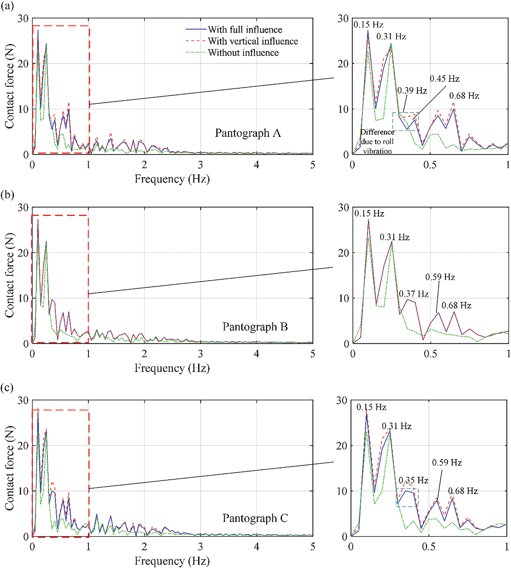
Figure 11: Frequency spectra of the pantograph-catenary contact force with different truck vibration influences considered: (a) pantograph A; (b) pantograph B; and (c) pantograph C
Pantograph-catenary powered heavy-duty truck systems (Electrical road system, ERS) have been developed in many countries to reach zero CO2 emissions and increase energy efficiency in long-distance road cargo transport. However, while the pantograph-catenary system directly affects the current collecting performance of the ERS, with many new pantographs invented, its dynamics under different pantograph structures and complex road roughnesses have not been fully investigated. In this work, the dynamics of the pantograph-catenary system in the ERS under different pantograph structures are investigated first. Based on the structure of the ERS, a reduced pantograph-catenary-truck-pavement interaction model is first built. Because the structure of the catenary and truck-pavement system is the same as that of existing systems, the reduced catenary model and reduced-plate model transmission method are used to model the pantograph-catenary and truck-road interaction system, where the arbitrary Lagrange-Euler method is applied in the modeling process to minimize the demand for calculation effort. By comparison, three different invented pantographs with different structures are analyzed and modeled as multibody systems, which are combined with the reduced pantograph-catenary interaction model. The parameters of one pantograph are measured, and the other two pantographs are assumed to have the same parameters to minimize the influence of parameters. The complex road roughness of China’s ore transportation road is also modeled. After the present model’s validation, the influence of truck-pavement interactions on pantograph-catenary dynamic behavior under different road roughnesses and vehicle velocities is investigated first, and then the dynamic behavior of different pantographs under complex road roughness in China’s ore transportation road is studied and compared. Finally, the vibration transmission mechanism of the ERS for different pantograph structures is analyzed.
Based on the investigation results, several conclusions are drawn:
(1) The truck-pavement interaction obviously influences the pantograph-catenary interaction dynamics. This not only extends the variation range of the contact force but also causes a difference between the contact forces at the left and right sides of the collector heads. This influence is mainly concentrated in the low-frequency domain at 0.3–0.7 Hz. Very bad road roughness levels and vehicle velocities higher than 80 km/h can even cause contact loss and greatly reduce the current collection quality. Moreover, unlike in the railway system, the roll motion of the car body results in the difference between the contact forces at the left and right sides. Therefore, it must be fully considered in the design process of the pantograph.
(2) The pantograph with only one upper and lower arm has the best dynamic performance in China’s ERS. With complex road roughness in China’s ore transportation road, the difference between the contact forces at the left and right sides of the pantograph is close to zero, and no contact loss occurs. This not only balanced the dynamic behavior of the pantograph but also increased the current collecting quality. Note that this pantograph is stiffer than other pantographs with two upper or lower arms, and can result in high catenary uplift (up to 73.4 mm), which may influence the dynamic performance of the catenary.
(3) The vibration transmission from the truck to the collector head is concentrated in the vertical vibration at 0.39, 0.45, and 0.68 Hz, and the roll vibration combines with the vertical vibration at approximately 0.39 Hz. Pantograph B, with two levels of stiffness-damping elements located in the central line, can isolate the roll vibration transmission, which results in a balance in the left and right contact forces. Thus, this structure is suggested for use in the ERS.
In the present work, the model is not validated due to the lack of an experiment, and the vibration transmission route in the real ERS system is not fully studied, which become the limitations of the present work. In our future work, based on both the Elonso test stands in TU Berlin and the test line in Zhuzhou, the present model will be further validated by measurement data in order to evaluate and compare. The Elonso test stand will also be used to investigate the functional and safety of certain behavioral aspects of pantograph-catenary interaction in the ERS. The present model will also be used to expand the test specifications and capacity of the Elonso test stand to allow pantographs to be tested in the laboratory for potential future widespread use.
Acknowledgement: This work is supported by the National Natural Science Foundation of China and Yunnan fundamental research projects.
Funding Statement: This work is supported by the National Natural Science Foundation of China (grant number 12302048, received by author Yan Xu) and Yunnan fundamental research projects (grant No. 202501AT070321, received by author Yan Xu).
Author Contributions: The authors confirm contribution to the paper as follows: study conception and design: Yan Xu, Weidong Zhu; data collection: Dietmar Gohlich, Sangyoung Park, William Zhendong Liu; analysis and interpretation of results: Yan Xu, Ziwei Zhou. Haiyang Qu; draft manuscript preparation: Yan Xu. Weidong Zhu, Ziwei Zhou. All authors reviewed the results and approved the final version of the manuscript.
Availability of Data and Materials: All relevant data are within the paper.
Ethics Approval: Not applicable.
Conflicts of Interest: The authors declare no conflicts of interest to report regarding the present study.
Appendix A Matrices of the Truck Dynamic Equation
In Eq. (18), there is
where MC, Mbf, Mws, MB, and MwB are the masses of the towing vehicle car body, towing vehicle front tire, towing vehicle rear tire, trailer car body, and trailer car tire, respectively. ICX and ICY are the second moments of the towing vehicle car body, and IBX and IBY are the second moments of the trailer car body, respectively.
where
In Eqs. (A3)–(A9), KSi (i = 1–4) is the stiffness of the truck suspension, lxi (i = 1–3) is the longitudinal distance between the tire and the carbody central, lx4 is the distance between the suspension and carbody central. lyC is the lateral distance between tires. Similiarly, there are
where
In Eqs. (A11)–(A17), CSi (i = 1–4) is the damping of the truck suspension.
References
1. Giuliano G, Dessouky M, Dexter S, Fang J, Hu S, Miller M. Heavy-duty trucks: the challenge of getting to zero. Transp Res Part D Transp Environ. 2021;93(1):102742. doi:10.1016/j.trd.2021.102742. [Google Scholar] [CrossRef]
2. Alanazi F. Electric vehicles: benefits, challenges, and potential solutions for widespread adaptation. Appl Sci. 2023;13(10):6016. doi:10.3390/app13106016. [Google Scholar] [CrossRef]
3. Deshpande P, de Saxe C, Ainalis D, Miles J, Cebon D. A breakeven cost analysis framework for electric road systems. Transp Res Part D Transp Environ. 2023;122(19):103870. doi:10.1016/j.trd.2023.103870. [Google Scholar] [CrossRef]
4. Mareev I, Sauer DU. Energy consumption and life cycle costs of overhead catenary heavy-duty trucks for long-haul transportation. Energies. 2018;11(12):3446. doi:10.3390/en11123446. [Google Scholar] [CrossRef]
5. Linke R, Wilke JK, Öztürk Ö, Schöpp F, Kassens-Noor E. The future of the eHighway system: a vision of a sustainable, climate-resilient, and artificially intelligent megaproject. J Mega Infrastruct Sustain Dev. 2022;2(sup 1):51–64. doi:10.1080/24724718.2022.2131087. [Google Scholar] [CrossRef]
6. Lee KY, Bühs F, Göhlich D, Park S. Towards reliable design and operation of electric road systems for heavy-duty vehicles under realistic traffic scenarios. IEEE Trans Intell Transp Syst. 2023;24(10):10963–76. doi:10.1109/TITS.2023.3280948. [Google Scholar] [CrossRef]
7. Hanesch S, Schöpp F, Göllner-Völker L, Schebek L. Life cycle assessment of an emerging overhead line hybrid truck in short-haul pilot operation. J Clean Prod. 2022;338(1):130600. doi:10.1016/j.jclepro.2022.130600. [Google Scholar] [CrossRef]
8. Jerrelind J, Drugge L, Trigell AS. Simulation of vehicle-overhead power system interaction on electric roads. In: Proceedings of the 13th Mini Conference on Vehicle System Dynamics, Identification and Anomalies; 2012 Nov 5–7; Budapest, Hungary. [Google Scholar]
9. Bruni S, Bucca G, Carnevale M, Collina A, Facchinetti A. Pantograph-catenary interaction: recent achievements and future research challenges. Int J Rail Transp. 2018;6(2):57–82. doi:10.1080/23248378.2017.1400156. [Google Scholar] [CrossRef]
10. Antunes P, Ambrósio J, Pombo J, Facchinetti A. A new methodology to study the pantograph-catenary dynamics in curved railway tracks. Veh Syst Dyn. 2020;58(3):425–52. doi:10.1080/00423114.2019.1583348. [Google Scholar] [CrossRef]
11. Song Y, Lu X, Yin Y, Liu Y, Liu Z. Optimization of railway pantograph-catenary systems for over 350 km/h based on an experimentally validated model. IEEE Trans Ind Inform. 2024;20(5):7654–64. doi:10.1109/TII.2024.3361485. [Google Scholar] [CrossRef]
12. Cheng Y, Yan J, Zhang F, Li M, Zhou N, Shi C, et al. Surrogate modeling of pantograph-catenary system interactions. Mech Syst Signal Process. 2025;224(5):112134. doi:10.1016/j.ymssp.2024.112134. [Google Scholar] [CrossRef]
13. Ling T, Cao R, Deng L, He W, Wu X, Zhong W. Dynamic impact of automated truck platooning on highway bridges. Eng Struct. 2022;262(1):114326. doi:10.1016/j.engstruct.2022.114326. [Google Scholar] [CrossRef]
14. Nassif HH, Liu M. Analytical modeling of bridge-road-vehicle dynamic interaction system. J Vib Control. 2004;10(2):215–41. doi:10.1177/1077546304033950. [Google Scholar] [CrossRef]
15. Savio D, Challa A, Subramanian SC, Krishnan JM. Influence of road profiles and truck braking on the dynamic load transfer to the pavement. Int J Pavement Eng. 2023;24(2):2090559. doi:10.1080/10298436.2022.2090559. [Google Scholar] [CrossRef]
16. Wang J, Wu J, Li Y. The driving safety field based on driver-vehicle–road interactions. IEEE Trans Intell Transp Syst. 2015;16(4):2203–14. doi:10.1109/TITS.2015.2401837. [Google Scholar] [CrossRef]
17. Xu Y, Liu ZD, Stichel S, Zhu WD, Lei JL, Yao Y. A comparative study on the influence of typical track failures on high-speed pantograph-catenary interaction dynamics. Veh Syst Dyn. 2024;62(11):2883–911. doi:10.1080/00423114.2024.2305295. [Google Scholar] [CrossRef]
18. Xu Y, Yang CJ, Zhu WD, Zhang WH. A reduced-plate model transmission method for fast dynamic analysis of vehicle-pavement interaction. J Sound Vib. 2023;548:117554. doi:10.1016/j.jsv.2023.117554. [Google Scholar] [CrossRef]
19. Xu Y, Zhu W, Fan W, Yang C, Zhang W. A new three-dimensional moving Timoshenko beam element for moving load problem analysis. J Vib Acoust. 2020;142(3):031001. doi:10.1115/1.4045788. [Google Scholar] [CrossRef]
20. Liu Z, Berg M, Ekmark A. Conceptual exploration of power peak shaving by smart train operation in rail freight transport. Proc Inst Mech Eng Part F J Rail Rapid Transit. 2022;236(7):838–49. doi:10.1177/09544097211045544. [Google Scholar] [CrossRef]
21. Trigell AS, Rothhämel M, Pauwelussen J, Kural K. Advanced vehicle dynamics of heavy trucks with the perspective of road safety. Veh Syst Dyn. 2017;55(10):1572–617. doi:10.1080/00423114.2017.1319964. [Google Scholar] [CrossRef]
22. Golov E, Evtyukov S, Protsuto M, Evtyukov S, Sorokina E. Influence of the road surface roughness (according to the International Roughness Index) on road safety. Transp Res Procedia. 2022;63(5):999–1006. doi:10.1016/j.trpro.2022.06.099. [Google Scholar] [CrossRef]
23. Hernandez JA, Al-Qadi IL. Tire-pavement interaction modelling: hyperelastic tire and elastic pavement. Road Mater Pavement Des. 2017;18(5):1067–83. doi:10.1080/14680629.2016.1206485. [Google Scholar] [CrossRef]
Cite This Article
 Copyright © 2025 The Author(s). Published by Tech Science Press.
This work is licensed under a Creative Commons Attribution 4.0 International License , which permits unrestricted use, distribution, and reproduction in any medium, provided the original work is properly cited.
 Downloads
 Citation Tools