
 Submit a Paper
 Propose a Special lssue
 Open Access
ARTICLE

Development of AI-Based Monitoring System for Stratified Quality Assessment of 3D Printed Parts
1 Department of Mechanical Convergence Engineering, Hanyang University, Seoul, 04763, Republic of Korea
2 Intelligent Manufacturing System R&D Department, Korea Institute of Industrial Technology, Cheonan-si, 31056, Republic of Korea
3 School of Mechanical Engineering, Hanyang University, Seoul, 04763, Republic of Korea
* Corresponding Authors: Jungsoo Nam. Email: ; Min Ku Kim. Email:
Computer Modeling in Engineering & Sciences 2026, 146(1), 21 https://doi.org/10.32604/cmes.2025.071817
Received 12 August 2025; Accepted 01 December 2025; Issue published 29 January 2026
 View Full Text
 Download PDF
Abstract
The composite material layering process has attracted considerable attention due to its production advantages, including high scalability and compatibility with a wide range of raw materials. However, changes in process conditions can lead to degradation in layer quality and non-uniformity, highlighting the need for real-time monitoring to improve overall quality and efficiency. In this study, an AI-based monitoring system was developed to evaluate layer width and assess quality in real time. Three deep learning models Faster Region-based Convolutional Neural Network (R-CNN), You Only Look Once version 8 (YOLOv8), and Single Shot MultiBox Detector (SSD) were compared, and YOLOv8 was ultimately selected for its superior speed, flexibility, and scalability. The selected model was integrated into a user-friendly interface. To verify the reliability of the system, bead width control experiments were conducted, which identified feed speed and extrusion speed as the key process parameters. Accordingly, a Central Composite Design (CCD) experimental plan with 13 conditions was applied to evaluate layer width and validate the system’s reliability. Finally, the proposed system was applied to the additive manufacturing of an aerospace component, where it successfully detected bead width deviations during printing and enabled stable fabrication with a maximum geometric deviation of approximately 6 mm. These findings demonstrate the critical role of real-time monitoring of layer width and quality in improving process stability and final product quality in composite material additive manufacturing.Keywords
Composite-based additive manufacturing (AM) has emerged as a promising approach for producing lightweight, high-strength structural components in transportation applications, particularly in aerospace and automotive sectors. Among the available AM techniques, material extrusion additive manufacturing (MEX), an adaptation of the fused filament fabrication (FFF) process, has been developed for the large-scale fabrication of thermoplastic composite structures using pelletized feedstock rather than filament [1]. This method offers key advantages, including high material utilization efficiency, greater geometric design flexibility, and the elimination of conventional tooling requirements.
During Material Extrusion (MEX) Additive Manufacturing, residual stress, part deformation, and property variations arise due to complex flow dynamics and thermal gradients [2]. Moreover, extrusion-based composite AM suffers from porosity, poor interlayer adhesion, bead geometry irregularity, surface roughness, and anisotropy, all of which degrade part performance [3]. Prior studies have shown that printed part quality in MEX is highly dependent on processing parameters. Multivariate statistical methods, such as principal component analysis (PCA), have been used to quantify the effects of extrusion temperature, layer thickness, bed temperature, and print speed on tensile strength [4]. Tensile performance is strongly linked to dimensional accuracy and interlayer bonding [5]. Porosity, a key defect, critically undermines strength and dimensional fidelity, making bead geometry control essential [6].
Traditionally, post-processing methods such as thermal and chemical treatments have been employed to reduce porosity and enhance the mechanical performance of AM parts [7]. Pre-processing quality assurance strategies have included polymer material optimization [8], toolpath planning, and parameter tuning to improve deposition uniformity and interlayer bonding [9,10]. However, these approaches are limited to pre- or post-processing and cannot adapt to in-process variations, while also incurring significant time and cost, particularly in large-scale manufacturing.
To address these limitations, recent research has focused on sensor-based process monitoring technologies for real-time defect detection, enabling in situ evaluation and improvement of AM quality. For example, in Fused Deposition Modeling (FDM), vision-based systems have been implemented to detect under- and over-extrusion conditions, with classification performed via convolutional neural networks (CNNs) [11]. Semantic segmentation approaches have been applied to localize and visualize extrusion defects at the pixel level [12]. Nozzle-integrated pressure and rheological sensors have been introduced to estimate flow behavior and viscosity in real time, particularly for non-Newtonian materials [13]. Strain sensor-based systems have shown potential for predicting delamination and warping by monitoring stress evolution during printing, thereby laying the groundwork for predictive maintenance [14]. Additionally, multimodal sensing approaches, combining temperature, vibration, and image-based data, have been integrated with machine learning techniques to develop advanced monitoring systems for defect detection and quality control [15]. However, in the context of large-scale additive manufacturing, more intuitive monitoring indicators are required to ensure quality. Consequently, there is a growing demand for vision-based monitoring systems capable of capturing direct and visible data, such as geometry and surface quality. For instance, in laser wire-based directed energy deposition (LW-DED), physical features such as melt pool area, brightness, and geometry have been extracted from in-situ images, and lightweight machine learning models have been employed to classify process stability in real-time [16]. In metal-based laser additive manufacturing (MLAM), closed-loop control systems have been implemented by integrating in-situ detection and adjustment to address issues of dimensional accuracy and surface quality [17].
Furthermore, vision sensor-based monitoring techniques developed in AM can also be extended to large-scale processes. Digital image correlation (DIC) enables non-contact, full-field strain measurement, and recent implementations using natural speckle patterns have demonstrated its applicability to large composite structures [18]. In concrete AM, vision-based monitoring systems have been employed to detect material flow deviations and perform automatic corrections [19]. In metal AM, vision-based monitoring uses welding camera analysis for spatter detection and wire position monitoring [20], and structured lighting with high-speed imaging has been applied to extract weld seam geometry and perform process control [21].
Nevertheless, no robust vision-based bead monitoring system has yet been demonstrated for meter-scale composite AM. Although several large-scale AM studies have been reported, most of them were limited to post-process analysis rather than true in-situ, real-time monitoring, and thus cannot support immediate defect detection and correction. Moreover, large-scale manufacturing environments impose additional challenges, such as high thermal loads, vibration, and optical distortions associated with increased build dimensions, which restrict the applicability of image-based data processing. As a result, existing studies remain largely focused on FDM or small-scale demonstrations, with insufficient scalability and inadequate implementation of real-time quality assurance in industrial systems. These limitations further underscore the need for process-specific monitoring strategies that establish standardized, quantitative quality metrics to enable closed-loop feedback control. To address this need, this study proposes a vision-based in-situ monitoring framework tailored to extrusion-based composite AM. By tracking bead width in real-time, a sensitive indicator of deposition quality, the system reliably detects process anomalies, thereby providing the foundation for adaptive, feedback-driven control. Furthermore, the framework has been validated in the additive manufacturing of aerospace components, demonstrating its effectiveness and practicality in industrial-scale applications.
As illustrated in Fig. 1a, this study addresses the fabrication of a composite mold for the rear cockpit section of the KF-21 fighter jet using an AM process. The mold serves as a critical tooling component for integrated forming of the cockpit frame and must satisfy three primary technical requirements: high dimensional accuracy, high structural stiffness, and low weight. These requirements stem from the fact that aircraft interior components are continuously subjected to aerodynamic vibration, pressure fluctuations, and thermal stress during flight, necessitating both structural integrity and geometric precision in their production.
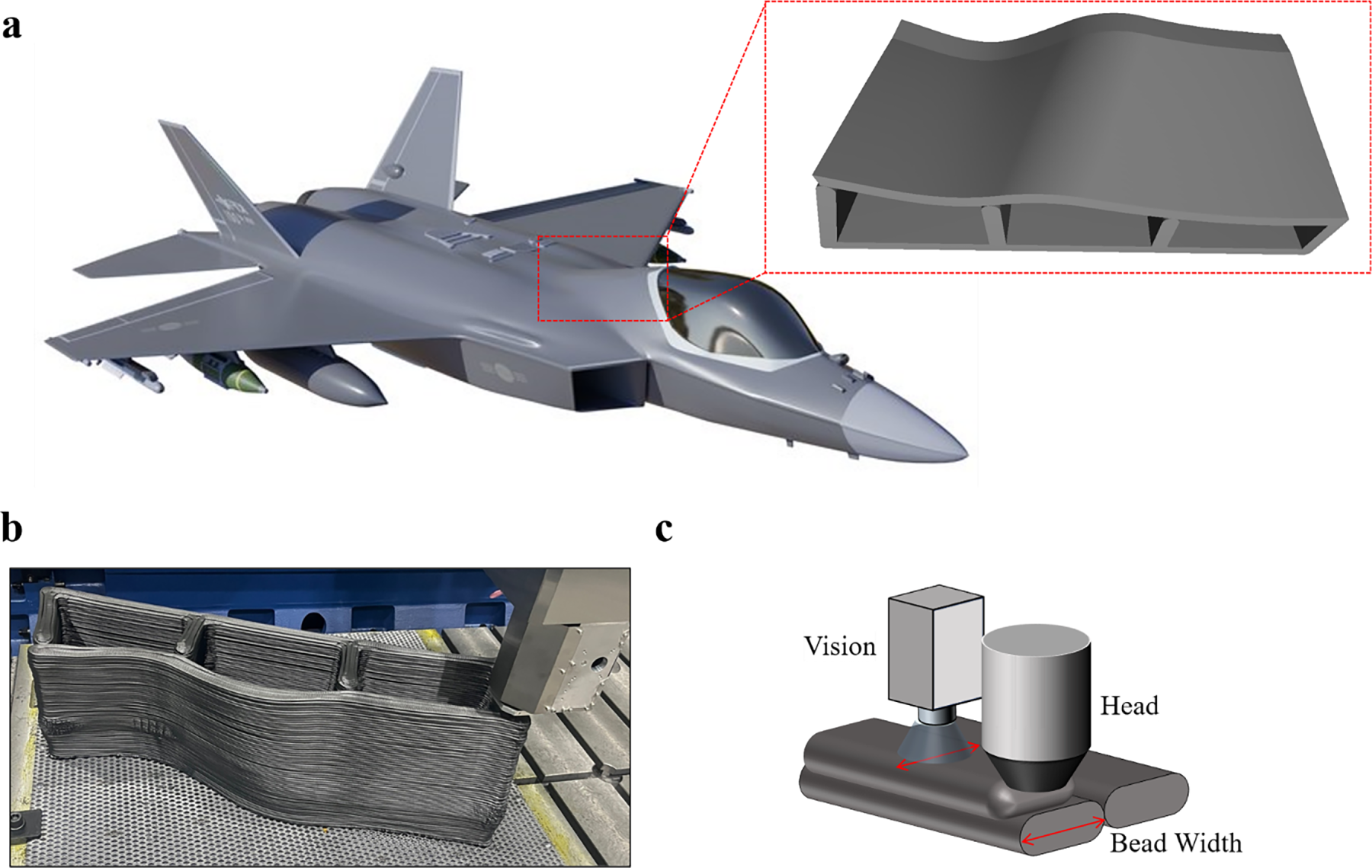
Figure 1: Large-scale material extrusion process; (a) Illustration of the printed part corresponding to the rear cockpit section of a KF-21 fighter jet; (b) On-site image of the component during the 3D printing process; (c) Vision monitoring system mounted on the extrusion nozzle: real-time bead width detection for in-situ monitoring
The aerospace industry has increasingly adopted carbon fiber-reinforced polymer (CFRP) for manufacturing lightweight structural parts due to its high strength-to-weight ratio, thermal resistance, and fatigue durability [22]. However, for large, highly curved interior components, conventional mold-based manufacturing processes are often inefficient in terms of productivity and cost. Large-scale AM, with its capability to produce complex and freeform geometries, offers a promising alternative [23]. In this work, a composite-based large-scale MEX process is employed to directly fabricate a mold applicable to actual aerospace parts, while simultaneously integrating a vision-based system for real-time monitoring of deposition quality.
The MEX process extrudes high-temperature thermoplastic composites in pellet form through a high-throughput extruder, depositing material layer by layer. While MEX process shares its fundamental principles with FFF, it is distinct in its ability to produce multi-meter-scale structures, support continuous pellet feed, process a wider range of material, and eliminate the need for tooling [24,25]. The overall system configuration and equipment used in this process are illustrated in Fig. 1b. Despite these advantages, MEX is highly sensitive to variations in thermal flow behavior, extrusion speed, nozzle temperature, and material viscosity. Such variations can lead to porosity, interlayer adhesion defects, and surface imperfections [26]. These deviations are often reflected in the geometry of the extruded bead, specifically its width, thickness, and continuity, making bead shape one of the earliest observable indicators of process quality [27]. Bead morphology reflects not only material distribution and thermal stability but also dynamic process anomalies such as nozzle clogging, temperature fluctuations, and under- or over-extrusion.
To meet the stringent requirements of lightweight design and structural durability in aerospace part manufacturing, a high-performance thermoplastic composite reinforced with chopped carbon fibers was employed. Specifically, the material used was an Acrylonitrile Butadiene Styrene (ABS) composite reinforced with 20 wt% chopped carbon fiber, commercially supplied as Trilac® ABS/CF20 by Samyang Corporation (Seoul, Republic of Korea). ABS is well known for its excellent impact resistance, processability, and thermal stability, making it widely used in the fabrication of industrial parts. The addition of carbon fiber significantly improves the mechanical strength and stiffness of the material [28]. Fig. 2a shows the appearance of the composite material used in the experiment.
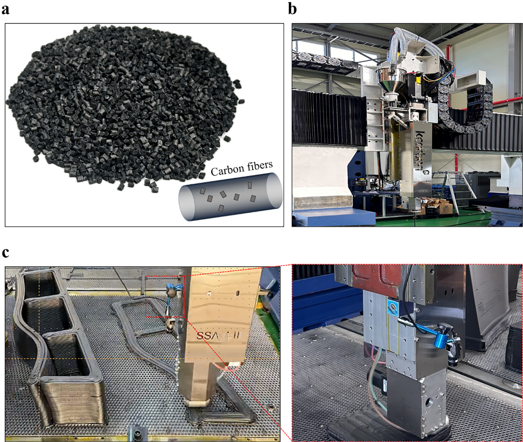
Figure 2: Materials and monitoring setup for large-scale extrusion-based additive manufacturing; (a) ABS reinforced with 20 wt% chopped carbon fiber (CFRP), provided by Samyang Corporation, used as the experimental material; (b) Large-scale additive manufacturing (LSAM) process during material extrusion; (c) Integration of the proposed vision monitoring framework with the LSAM system using a Basler acA3088-16gm camera, illustrating the practical implementation for bead geometry tracking during deposition
The selected material also contributes to reducing shrinkage and deformation during printing, thus helping to maintain the geometric stability of large-scale parts. Prior to extrusion, the material was dried to eliminate moisture, thereby preventing bubble formation and internal defects during the deposition process. The additive manufacturing experiments in this study were carried out using a large-scale extrusion-based additive manufacturing (Fig. 2b), which is a custom-built research-purpose machine fabricated by Korea Carbon Industry Promotion Agency (Jeonju City, Republic of Korea). The system is equipped with a working table of 2.0 × 1.0 × 1.3 m, and a 5 mm printing nozzle. It can reach a maximum processing temperature of 420°C with a position resolution of 3 μm. The resulting bead dimensions were approximately 7 mm × 2.5 mm (Fig. 2b). Basler acA3088-16 gm industrial camera was employed, fixed at a specific distance and angle relative to the nozzle to ensure stable frame capture and a consistent field of view even during high-speed motion (Fig. 2c). Because the camera looks downward at the print bed (a fixed ground plane), the background remains constant and is largely unaffected by changes in the surrounding environment. In addition, the camera shares the print-head calibration, maintaining a constant relative pose that mitigates vibration-induced variation. This configuration effectively suppresses external industrial noise and enables reliable, real-time monitoring of bead geometry. Since bead width is highly sensitive to changes in process variables such as extrusion inconsistency, temperature fluctuations, and material feed issues, real-time tracking helps prevent quality degradation.
The integrated experimental setup combining high-performance composite material, a large-scale AM platform, and a high-speed vision system provides a realistic industrial testbed to verify the performance of the proposed bead monitoring algorithm under practical conditions.
Bead cross sectional area is a primary determinant of interlayer quality. The normalized weld strength
Ultimately, interlayer quality is controlled by the equivalent isothermal time computed from the interface temperature history
Thus, the bead cross section is a direct determinant of quality. Smaller sections increase the inter bead void fraction and degrade mechanical properties [30], whereas larger sections promote heat accumulation, leading to residual stresses and warpage in large-format extrusion [31]. To address these quality defects, we select a practical bead size that accounts for the material-specific cooling conditions. Equally important, we maintain this bead size during processing; to that end, this work proposes a vision-based framework for real-time bead monitoring.
To monitor bead geometry in real-time during the AM process, a camera-based vision system was mounted on the extrusion head, allowing continuous frame-by-frame image acquisition. The camera, moving in synchrony with the extrusion head, captured the bead formation immediately after deposition, allowing for the detection of dynamic shape changes and potential defects throughout the process. In practical experimental conditions, however, accurately extracting bead contours from captured images proved challenging due to environmental noise and process-related disturbances (Fig. 3a). Variations in lighting, nozzle vibration, background reflections, and thermal color distortion of the deposited material significantly degraded image clarity, hindering precise bead recognition. To address these challenges, region-of-interest (ROI) detection (Fig. 3b) was incorporated as a core step. Yet, the constant movement of the extrusion head made fixed-ROI approaches unreliable for consistent analysis over time. In response, an adaptive image analysis framework was developed to maintain accurate bead width measurement under changing process conditions.
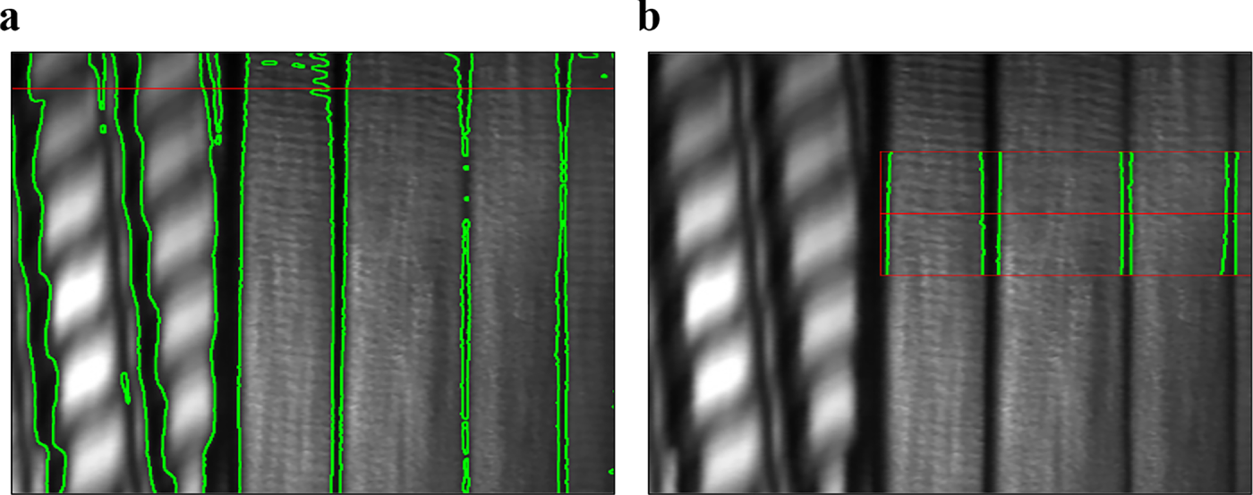
Figure 3: Noise according to Region of Interest (ROI); (a) Without ROI; (b) Set ROI
As shown in Fig. 4, the proposed system comprises four main stages: (i) data acquisition, (ii) ROI detection, (iii) bead segmentation, and (iv) width measurement. Central to the methodology is dynamic ROI allocation, in which a new ROI is assigned for each frame based on the current bead position. This ensures localized, high-precision analysis even in continuous motion environments, where static ROIs often lead to background interference or partial bead capture.
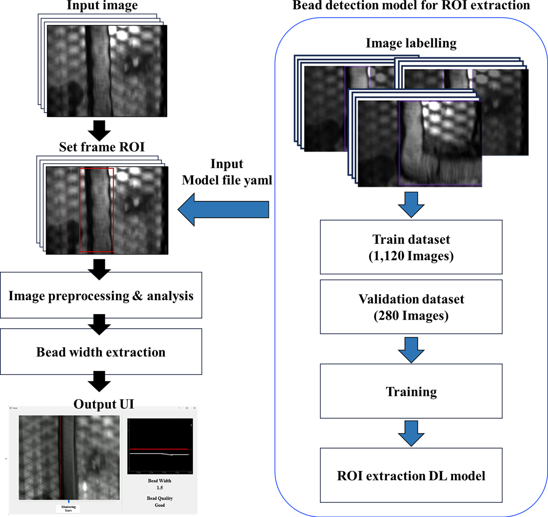
Figure 4: Workflow of the DL-based vision monitoring framework
A deep learning–based object detection model was employed for ROI assignment. This model rapidly predicts the region most likely to contain the bead, allowing targeted analysis within that area only. Compared with conventional thresholding or edge-based techniques, the deep learning approach demonstrated robust performance against lighting variations, background noise, and motion blur, while supporting real-time inference on each frame, even in high-speed printing scenarios. The resulting bead-width measurement framework features a flexible and adaptive architecture designed to operate reliably under environmental uncertainty. By delivering accurate and consistent bead geometry analysis, it establishes a solid foundation for achieving high-quality, real-time controlled additive manufacturing processes.
3.1 Select Region of Interest (ROI) Detection Model
The vision system mounted on the extrusion head operates at a high speed of up to 2000 mm/min, necessitating the robust and accurate detection of beads in real-time under varying environmental conditions. To achieve this, selecting an appropriate object detection model based on deep learning is critical. Notably, in this study, the Region of Interest (ROI) was defined as the area of the bead extruded during the AM process. If defined statically, the rapid movement of the extrusion head may cause the actual bead to fall outside the predefined area. Hence, a detection model capable of dynamically identifying ROIs with stability in real-time settings is essential. In this study, several object detection models were compared and analyzed to identify the optimal approach for real-time bead recognition. Object detection involves predicting the class and bounding box coordinates of objects within an image.
To this end, we compared three representative object detection models: Faster R-CNN, SSD-MobileNet V2, and YOLOv8. Object detection models are generally categorized into two-stage and one-stage approaches [32]. Faster R-CNN, a two-stage detector, provides high detection accuracy but suffers from relatively slow inference speed, which restricts real-time applicability [33]. SSD-MobileNet V2, a lightweight one-stage model, achieves fast inference and efficiency, but its accuracy tends to decline under complex backgrounds or low-contrast conditions [34]. YOLOv8, the latest one-stage detector, introduces an anchor-free architecture with improvements in both detection speed and accuracy over YOLOv5 [35,36]. It combines high accuracy with real-time performance, demonstrating robust operation across diverse bead shapes and lighting conditions. The architectural characteristics of these models are summarized in Fig. 5, while the rationale for selecting YOLOv8 as the final model is discussed in the subsequent section.
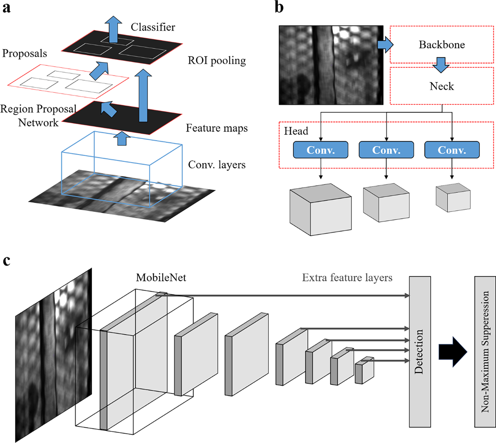
Figure 5: Printing bead (ROI) detection algorithm Architecture; (a) Faster R-CNN; (b) YOLOv8; (c) SSD
Although deep learning models generally require large datasets, the images in this study were collected directly from our extrusion-based AM process, ensuring high relevance to the target application. Despite the relatively small scale, a custom dataset of 1400 real bead images was sufficient for model training and validation. The dataset was split randomly into 80% for training and 20% for validation, reflecting a wide range of bead shapes and lighting conditions. Data augmentation techniques such as Random Horizontal Flip and Random Brightness Adjustment were applied to enhance generalization under various lighting and orientation scenarios. While this dataset was adequate for the present material system, if a different polymer, color, or surface finish is used, additional images for fine-tuning would be required to maintain detection accuracy. All models were trained under consistent conditions: Batch Size = 32, Epochs = 100, Optimizer = Adam. During training, both training loss and validation loss were monitored to evaluate overfitting.
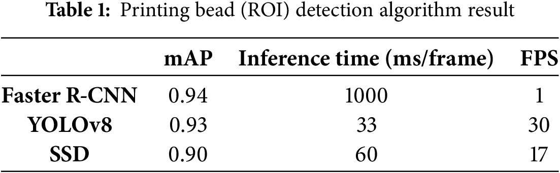
In Table 1, mean Average Precision (mAP) represents the detection accuracy of bead regions, FPS (frames per second) indicates the overall processing throughput, and inference time (ms/frame) denotes the computational latency for processing a single image. Together, these metrics provide a comprehensive evaluation of each algorithm’s suitability for real-time monitoring. All models achieved an accuracy of over 0.90, but with notable differences. Faster R-CNN demonstrated the highest accuracy; however, its two-stage architecture resulted in slow inference, making it unsuitable for real-time applications. SSD-MobileNet V2 achieved fast processing speed and was computationally lightweight, making it promising for some real-time scenarios. However, it exhibited unstable performance in low-contrast conditions. YOLOv8 provided a balanced performance in both accuracy and speed, and its modular PyTorch implementation with CUDA optimization enabled seamless integration into real-time monitoring systems.
In addition, the Receiver Operating Characteristic (ROC) curves shown in Fig. 6 further validate these findings. Faster R-CNN achieved the highest area under the curve (AUC ≈ 0.947), indicating superior detection accuracy, but its low FPS limits real-time applicability. SSD-MobileNet V2 yielded a slightly lower AUC (≈0.914), yet maintained the fastest inference speed. YOLOv8 achieved an AUC of approximately 0.942, demonstrating both high accuracy and real-time speed, thereby confirming its role as the most balanced and practical model for dynamic extrusion-based additive manufacturing.
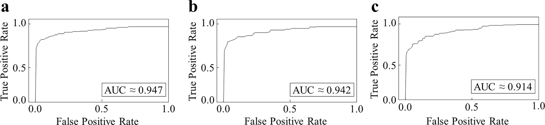
Figure 6: ROC Graph; (a) Faster R-CNN; (b) YOLOv8; (c) SSD
Based on the results, YOLOv8 was selected as the final object detection model for this study. It provided the best trade-off between bead recognition accuracy and real-time processing speed. Furthermore, its modular architecture, GPU acceleration support, and adaptability to various lighting and shape conditions, enabled by data augmentation, demonstrated superior robustness and applicability in real-world manufacturing environments. YOLOv8 also showed fast convergence and stable training curves without overfitting, validating its suitability for deployment in dynamic extrusion-based additive manufacturing settings.
3.2 Image Data Pre-Processing & Analysis Process
In this study, an image pre-processing and analysis algorithm was designed to dynamically update the Region of Interest (ROI) based on bead recognition and precisely measure bead width within the extracted ROI. The ROI was defined to cover only the local deposition area around the bead (approximately 10 mm × 30 mm in physical scale, based on camera calibration), ensuring that the contour was fully included while excluding unnecessary background. A key objective of the algorithm is the accurate detection of bead contours, for which a lightweight implementation based on the Canny Edge Detection algorithm was developed.
Canny Edge Detection is a traditional edge extraction method that offers both robustness and computational efficiency [37,38]. It ensures stable contour detection even under complex backgrounds and, due to its fast processing speed, is highly suitable for real-time additive manufacturing environments. As illustrated in Fig. 7a, the Canny Edge algorithm was applied to isolate bead contours effectively.
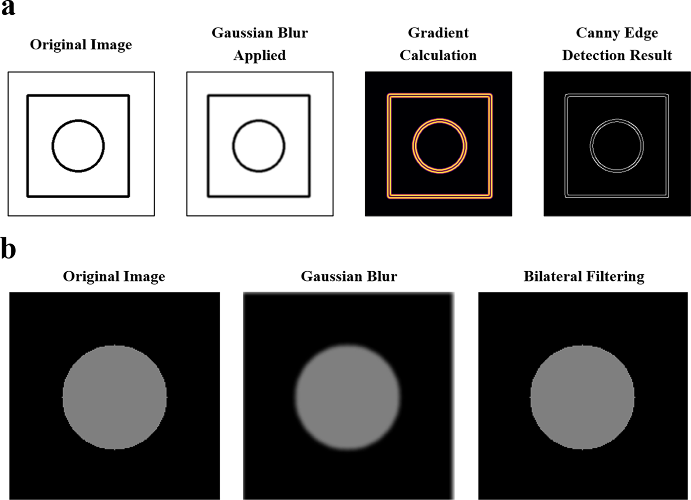
Figure 7: Image preprocessing method; (a) Canny Edge Algorithm; (b) Compared Gaussian Blur & Bilateral Filter
To further enhance contour accuracy, Bilateral Filtering was applied prior to edge detection [39]. Unlike conventional Gaussian smoothing, Bilateral Filtering removes background noise while preserving sharp edges, which is advantageous for extracting bead boundaries without blurring. This effect is clearly shown in Fig. 7b, where Bilateral Filtering provides superior edge preservation compared to Gaussian Blur, thereby improving the reliability of bead contour extraction.
The complete bead width measurement process is illustrated in Fig. 8. The algorithm first applies Bilateral Filtering to the input image within the dynamically detected ROI. Next, Canny Edge Detection is used to extract the bead contours. The pixel distance between detected contour edges is then calculated and multiplied by a calibration coefficient (pixel-to-mm ratio) to derive the final bead width. This coefficient was obtained through a camera calibration process using a calibration board, where physical measurements were compared with corresponding pixel distances.
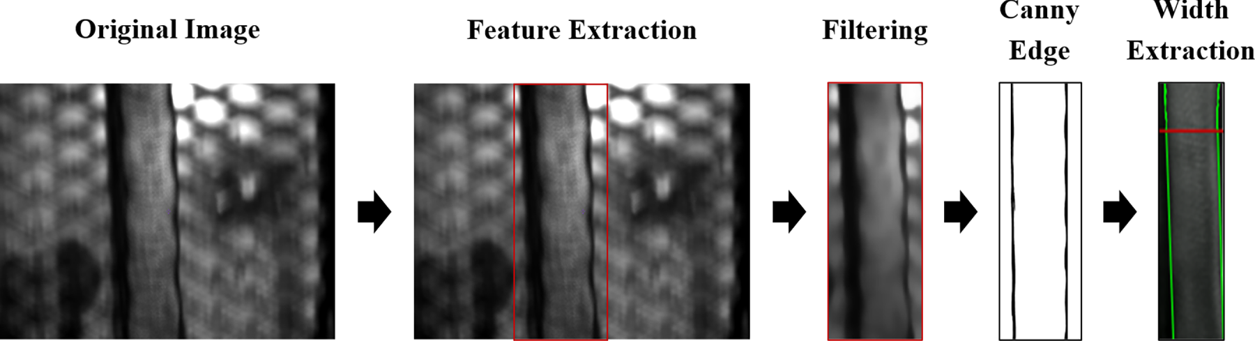
Figure 8: Image preprocessing & analysis process
The entire algorithm was implemented in Python with the OpenCV library, and the average processing time was measured at approximately 2.2 ms per frame, satisfying real-time video processing requirements. In conclusion, the proposed algorithm provides a reliable and efficient approach for bead contour extraction and width estimation in dynamic AM environments. It simultaneously ensures edge detection accuracy, real-time responsiveness, and computational efficiency, while serving as a foundation for future extensions such as separating outer and inner contours for layer-by-layer quality analysis in large-scale additive manufacturing.
In this study, inspired by previous research indicating that nozzle feed speed and material extrusion speed significantly influence bead geometry characteristics, such as width, thickness, and surface quality, these two variables were selected as the primary process parameters [40]. The objective was to quantitatively analyze changes in bead geometry resulting from variations in the ratio of these parameters. In particular, it was observed that excessively high feed speeds or insufficient extrusion speeds result in under-extrusion, which can lead to bead breakage or reduced thickness. Conversely, excessively high extrusion speeds result in over-extrusion, leading to excessive bead formation or degradation in surface quality. Based on these observations, the process conditions were systematically designed with a focus on the interaction between feed speed and extrusion speed, and the sensitivity of bead geometry to these parameters was quantitatively assessed through experiments. Prior to the experimental design, considerations were given to minimizing material consumption and experimental costs by reducing the number of trials while still accurately quantifying changes in bead geometry and identifying the optimal process conditions. Consequently, Central Composite Design (CCD) was adopted as the experimental design method for process optimization. CCD, a technique within the response surface methodology (RSM), allows for the analysis of linear, nonlinear interactions, and quadratic effects with relatively few experiments. In this study, 13 experimental conditions were established for the two variables, feed speed and extrusion speed, including center points, axial points, and factorial points. The selected experimental conditions are shown in Table 2. The levels of each variable were set according to the fundamental principles of CCD at minimum (−α), center (0), and maximum (+α) values, with the α value set at 1.414 to ensure repeatability and normality of the experiments.
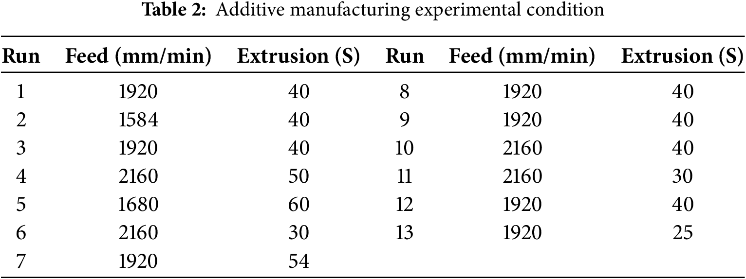
This design approach offers superior predictive power with fewer experimental runs compared to conventional full factorial designs, making it suitable for analyzing complex and highly nonlinear AM process variables. The experiments employed ABS + chopped CFRP (20 wt%) composites, the same material as the planned target part. The material underwent a pre-print drying process to minimize moisture content, and the deposition temperature was fixed at 260°C. Other parameters, including nozzle diameter, layer height, bed temperature, and ambient temperature, were deliberately kept constant (see Table 3) to ensure experimental reliability and eliminate their influence as variables. This was consistent with the study’s focus on verifying the applicability of the proposed real-time monitoring algorithm, for which feed speed and extrusion speed were selected as the primary variables affecting bead geometry.
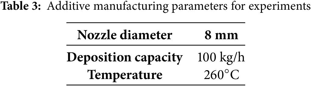
Furthermore, as illustrated in Fig. 9, a test pattern that accentuates bead geometry was designed and printed for each experimental condition to facilitate clear visual observation. Beads produced under each process condition were independently deposited, and a vision-based monitoring system was developed to automatically measure bead width.
Figure 9: Experiment process; (a) Experiment Part G-Code; (b) Experiment part result
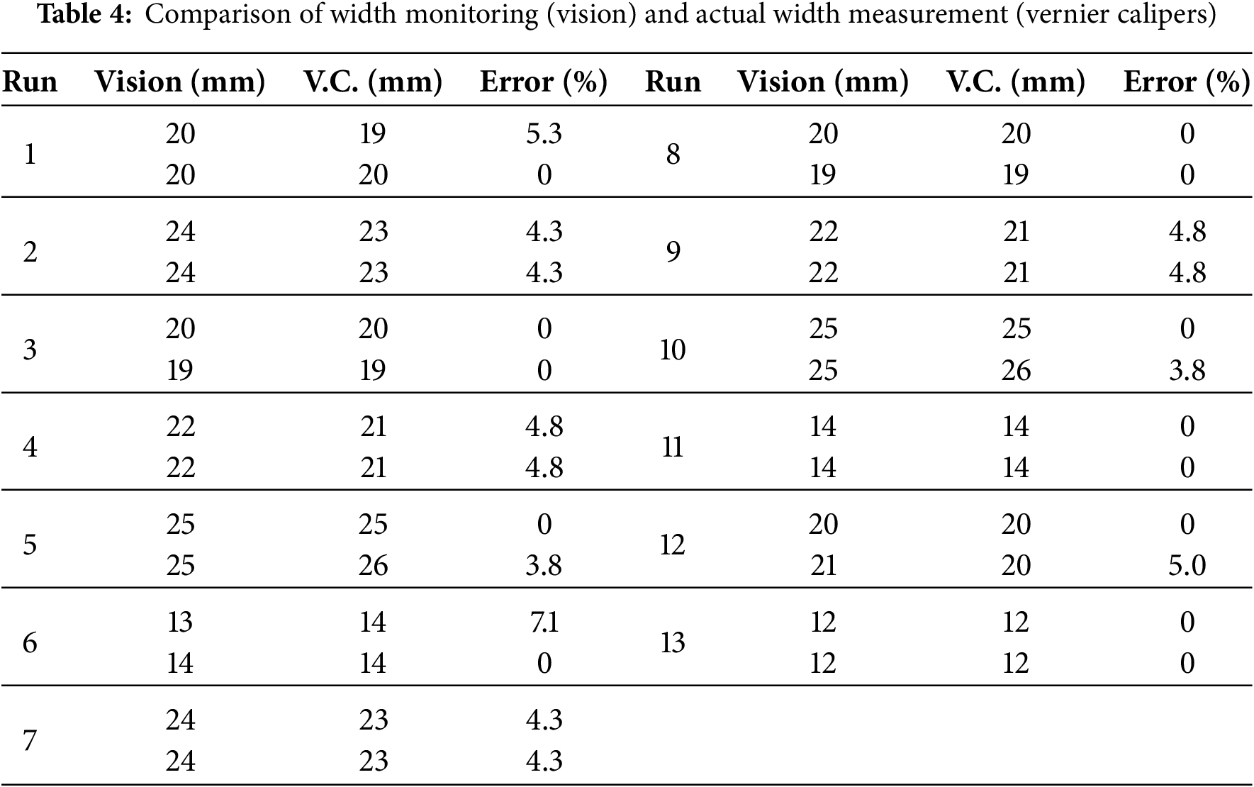
To validate the accuracy and reliability of the developed vision-based bead width measurement monitoring system, a comparative analysis was conducted between bead width data collected from the system and physical measurements. Experiments were conducted under 13 different printing conditions, and bead widths of the fabricated specimens were directly measured using a Vernier caliper, which offers a high measurement precision with an error margin of ±0.02 mm. The mechanically obtained measurements served as reference values for the vision-based system. To ensure data consistency, measurements were repeated at the same location at least three times for each experimental condition, and the average values were calculated and compared with the measurements obtained from the vision system. The mean relative error was 2.36% (max. 7.1%), with most conditions within 5% (Table 4). This level of accuracy implies that the system can detect bead width deviations with high reliability, thereby enhancing defect detection and increasing confidence in process control.
Guided by volume conservation, the bead cross-section
Eq. (3) quantifies how bead width
This yields
Accordingly, Eq. (5) provides a compact relation to compute the operating ratio for a target width, while substituting
Despite being based on a camera-driven vision measurement approach, the system consistently maintained stable contour recognition and bead width measurement performance, exhibiting minimal susceptibility to environmental variables such as lighting fluctuations, post-extrusion thermal deformation, and residual material accumulation around the nozzle. Validation using the CCD-based experimental configuration confirmed that the vision-derived bead width measurements closely matched physically measured values, demonstrating the high reliability of the system’s quality assessment capabilities. In contrast to conventional bead quality evaluation methods, which often require halting the process or destructively sectioning completed specimens for physical measurement, thereby disrupting production flow, complicating repeated assessments, and introducing variability due to measurement timing, the developed vision-based real-time monitoring system enables continuous, non-intrusive data acquisition and analysis without interrupting the additive manufacturing process. This capability not only facilitates immediate quality feedback and process control for bead geometry but also offers significant improvements over traditional manual measurement approaches in terms of precision, productivity, and operational practicality. As such, the proposed system represents a rapid, accurate, and fully automated alternative for measuring bead width, with strong potential to enhance real-time quality assurance in additive manufacturing applications.
To verify the applicability of the developed vision-based bead monitoring system in real-world environments, additive manufacturing experiments were conducted using an actual aerospace component. The test subject was the rear cockpit frame structure of the KF-21 fighter jet. Stable deposition process conditions, derived from prior simulation data and experimental analysis, were applied to fabricate the part using 3D printing. Notably, the component included curved and complex outer geometries, making the uniformity of extrusion a critical factor. During the experiment, the vision-based monitoring system was deployed in real-time under the predefined process parameters. The system was configured to trigger alerts upon detecting bead geometry anomalies, such as width imbalances, discontinuities, or deviations, allowing the operator to identify and respond to issues promptly. This implementation not only ensured real-time process stability but also established a continuous quality monitoring system without interruptions, demonstrating the system’s effectiveness in a real manufacturing environment.
The material used for the experiments was the same ABS + chopped CFRP (20 wt%, Samyang Corporation) composite applied in earlier tests. The deposition speed was set between 70 and 90 mm/s to reflect actual industrial processes, considerably faster than typical FDM methods. Such high-speed deposition often leads to increased geometric instability and bonding defects due to insufficient cooling of the material before subsequent bead deposition. To address these challenges, the deposition strategy was modified compared to that used in previous trials. Specifically, the number of beads increased from one to four, and the CAD model wall thickness was adjusted to fill potential void regions.
Repeated experiments under varying bead width conditions revealed that a bead width of 12 mm provided the most uniform deposition geometry with the lowest porosity. This conclusion was based on real-time contour data collected by the vision system. Through repeated trials, this condition exhibited the highest consistency in shape replication and the least variability in porosity ratio, offering a quantitative foundation for future process optimization and feedback control design.
The results of applying the proposed vision-based bead width monitoring system to the deposition process of the KF-21 rear cockpit component are shown in Fig. 10. Fig. 10a displays the real-time image data of the beads, illustrating how the model automatically detects the region of interest (ROI) and measures bead width as the extrusion head moves. The system achieved real-time analysis at 30 FPS, with bead widths recorded frame by frame to allow tracking of shape variations over time.
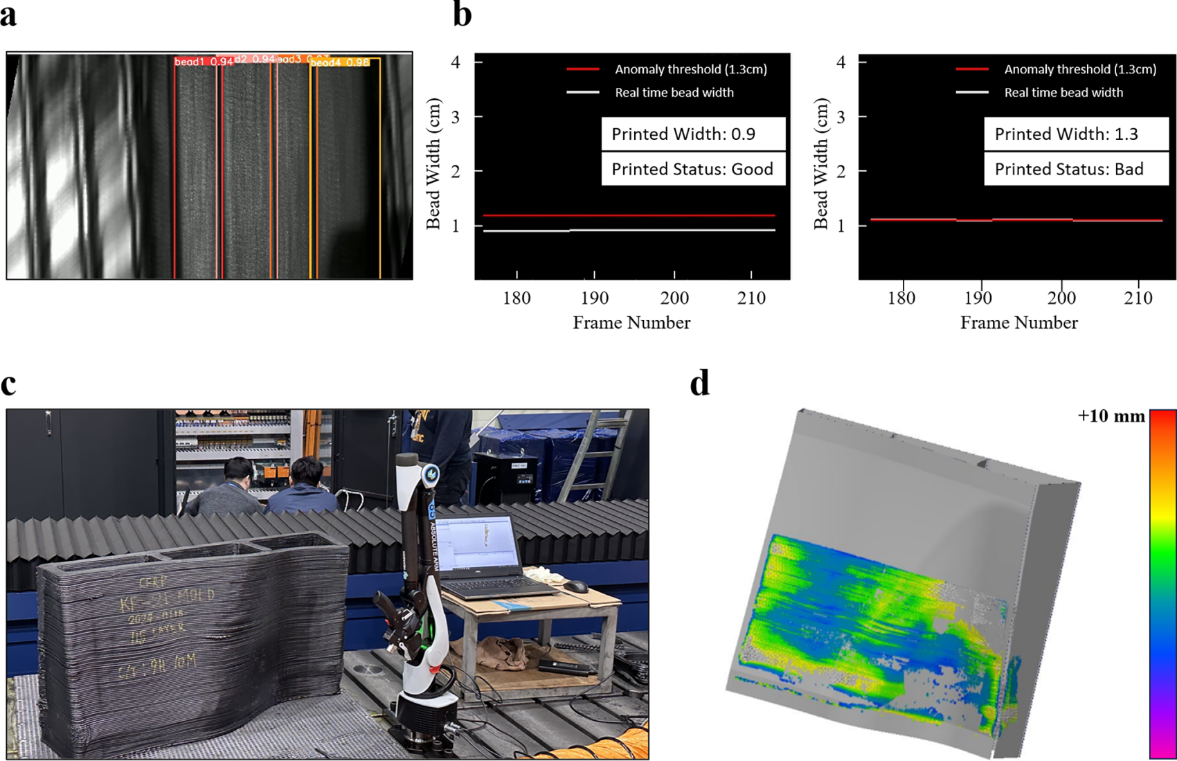
Figure 10: Application of monitoring system-KF-21 Part; (a) Bead monitoring images of the KF-21 part; (b) Frame-by-frame bead width measurements obtained using the proposed algorithm; (c) Final output of the KF-21 part and quality evaluation using the Absolute Arm laser scanner (8525-7/RSS, Hexagon); (d) Comparison between the CAD model and the actual dimensions measured by the 3D scanner
Fig. 10b shows that the measured bead widths remained close to the target value of 12 mm throughout the frames, though minor anomalies were detected in some frames. For instance, temporary reductions in bead width were observed due to momentary decreases in extrusion speed or slight bead oscillations caused by head vibrations. These irregularities were identified through deviation patterns in quantitative width data and could be integrated into a real-time alert system by setting tolerance thresholds.
Fig. 10c presents the complete KF-21 printed component, demonstrating the accuracy of the shape and the uniformity of bead patterns. To obtain precise dimensional measurements of the part, a 3D shape scan was performed using an Absolute Arm laser scanner (8525-7/RSS, Hexagon, Stockholm, Sweden), a high-precision articulated measuring device with a repeatable precision of ±0.03 mm, commonly used for industrial dimensional inspections. Fig. 10d compares the scanned geometry with the CAD model, revealing that the overall geometric deviation remained within 6 mm. This indicates that despite the effects of shrinkage and material flow characteristics inherent to large-scale composite additive manufacturing, the dimensional accuracy remained within practical limits.
Through the additive manufacturing experiments using a complex-shaped aerospace component, the applicability and technical validity of the vision-based bead monitoring system were empirically demonstrated. Even under modified deposition conditions involving four beads, the proposed system successfully recognized each bead individually. It precisely measured their widths in real time, highlighting its scalability and adaptability to multi-bead structures. Furthermore, the algorithmic architecture and sensor parameters established during preliminary experiments proved effective in the actual deposition process, demonstrating the system’s potential as a core infrastructure for real-time quality control and feedback-based process management.
This study developed a vision-based bead width monitoring system as a foundation for real-time quality assessment and control in composite additive manufacturing. Trained on 1400 image samples, the system achieved approximately 97% accuracy in bead width detection and quality anomaly identification, demonstrating robust reliability under varied process conditions. Real-time analysis was performed at an average processing speed of 35 ms per frame, enabling efficient in-process control.
The system was successfully implemented in the additive manufacturing of a KF-21 fighter jet rear cockpit mock-up component, maintaining the target bead width of 12 mm with high consistency. Validation against laser scanner measurements confirmed that deposition accuracy was achieved within a maximum deviation of approximately 6 mm, further substantiating the system’s effectiveness. Even in the fabrication of geometrically complex aerospace components, the monitoring framework provided timely and accurate data, enhancing operator decision-making and enabling immediate detection and correction of process anomalies. This capability significantly contributed to improving manufacturing efficiency and the stability of quality.
While the present evaluation focused solely on bead width, certain process conditions, such as severe vibration, temperature fluctuations, or nozzle clogging, may challenge detection accuracy. Addressing these scenarios will require further functional verification using more diverse field data. Future research will aim to expand the monitoring scope beyond bead geometry to include additional quality indicators such as joint integrity, enabling comprehensive real-time assessment and closed-loop feedback control. With these advancements, the proposed vision-based system is expected to evolve into a fully integrated technology that not only ensures precise, reliable monitoring of aerospace part production but also incorporates automated process optimization to enhance product quality.
Acknowledgement: The authors would like to thank Korea Institute of Industrial Technology, Ministry of Trade, Industry & Energy (MOTIE, Republic of Korea) for their support.
Funding Statement: This study has been conducted with the support of the Korea Institute of Industrial Technology as “Development of a remote manufacturing system for high-risk, high-difficulty pipe production processes” (kitech EH-25-0004) and This work was supported by the Technology Innovation Program (or Industrial Strategic Technology Development Program) (RS-2023–00237714, Development of Dynamic Metrology Tool for CMP Process Stabilization; RS-2025–02634755, Development of Real-Time Electrical Fire Prevention System Technology Reflecting the Characteristics of Traditional Markets) funded by the Ministry of Trade, Industry & Energy (MOTIE, Republic of Korea).
Author Contributions: Conceptualization: Yewon Choi, Jungsoo Nam and Song Hyeon Ju; Methodology: Yewon Choi; Software: Yewon Choi; Validation: Yewon Choi and Song Hyeon Ju; Formal analysis: Yewon Choi; Investigation: Yewon Choi, Jungsoo Nam and Song Hyeon Ju; Resources: Min Ku Kim; Data curation: Min Ku Kim; Writing—original draft preparation: Yewon Choi; Writing—review and editing: Min Ku Kim; Supervision: Jungsoo Nam and Min Ku Kim; Funding acquisition: Jungsoo Nam and Min Ku Kim. All authors reviewed the results and approved the final version of the manuscript.
Availability of Data and Materials: Data available on request from the authors. The source codes supporting the findings of this study are openly available at GitHub (https://github.com/dndlddndlddld/bead-width-UI.git, accessed on 01 January 2025).
Ethics Approval: Not applicable.
Conflicts of Interest: The authors declare no conflicts of interest to report regarding the present study.
References
1. Goh GD, Yap YL, Tan HKJ, Sing SL, Goh GL, Yeong WY. Process-structure–properties in polymer additive manufacturing via material extrusion: a review. Crit Rev Solid State Mater Sci. 2020;45(2):113–33. doi:10.1080/10408436.2018.1549977. [Google Scholar] [CrossRef]
2. Peng F, Vogt BD, Cakmak M. Complex flow and temperature history during melt extrusion in material extrusion additive manufacturing. Addit Manuf. 2018;22:197–206. doi:10.1016/j.addma.2018.05.015. [Google Scholar] [CrossRef]
3. Duty CE, Kunc V, Compton B, Post B, Erdman D, Smith R, et al. Structure and mechanical behavior of big area additive manufacturing (BAAM) materials. Rapid Prototyp J. 2017;23(1):181–9. doi:10.1108/rpj-12-2015-0183. [Google Scholar] [CrossRef]
4. Braconnier DJ, Jensen RE, Peterson AM. Processing parameter correlations in material extrusion additive manufacturing. Addit Manuf. 2020;31:100924. doi:10.1016/j.addma.2019.100924. [Google Scholar] [CrossRef]
5. Pang R, Lai MK, Ismail KI, Yap TC. Characterization of the dimensional precision, physical bonding, and tensile performance of 3D-printed PLA parts with different printing temperature. J Manuf Mater Process. 2024;8(2):56. doi:10.3390/jmmp8020056. [Google Scholar] [CrossRef]
6. Sun X, Mazur M, Cheng CT. A review of void reduction strategies in material extrusion-based additive manufacturing. Addit Manuf. 2023;67:103463. doi:10.1016/j.addma.2023.103463. [Google Scholar] [CrossRef]
7. Peng X, Kong L, Fuh JYH, Wang H. A review of post-processing technologies in additive manufacturing. J Manuf Mater Process. 2021;5(2):38. doi:10.3390/jmmp5020038. [Google Scholar] [CrossRef]
8. Côté R, Demers V, Demarquette NR, Charlon S, Soulestin J. A strategy to eliminate interbead defects and improve dimensional accuracy in material extrusion 3D printing of highly filled polymer. Addit Manuf. 2023;68:103509. doi:10.1016/j.addma.2023.103509. [Google Scholar] [CrossRef]
9. Eiliat H, Urbanic J. Determining the relationships between the build orientation, process parameters and voids in additive manufacturing material extrusion processes. Int J Adv Manuf Technol. 2019;100(1):683–705. doi:10.1007/s00170-018-2540-6. [Google Scholar] [CrossRef]
10. Jin YA, He Y, Fu JZ, Gan WF, Lin ZW. Optimization of tool-path generation for material extrusion-based additive manufacturing technology. Addit Manuf. 2014;1:32–47. doi:10.1016/j.addma.2014.08.004. [Google Scholar] [CrossRef]
11. Jin Z, Zhang Z, Gu GX. Autonomous in situ correction of fused deposition modeling printers using computer vision and deep learning. Manuf Lett. 2019;22:11–5. doi:10.1016/j.mfglet.2019.09.005. [Google Scholar] [CrossRef]
12. Jin Z, Zhang Z, Ott J, Gu GX. Precise localization and semantic segmentation detection of printing conditions in fused filament fabrication technologies using machine learning. Addit Manuf. 2021;37:101696. doi:10.1016/j.addma.2020.101696. [Google Scholar] [CrossRef]
13. Coogan TJ, Kazmer DO. In-line rheological monitoring of fused deposition modeling. J Rheol. 2019;63(1):141–55. doi:10.1122/1.5054648. [Google Scholar] [CrossRef]
14. Jin Z, Zhang Z, Gu GX. Automated real-time detection and prediction of interlayer imperfections in additive manufacturing processes using artificial intelligence. Adv Intell Syst. 2020;2(1):1900130. doi:10.1002/aisy.201900130. [Google Scholar] [CrossRef]
15. Oleff A, Küster B, Stonis M, Overmeyer L. Process monitoring for material extrusion additive manufacturing: a state-of-the-art review. Prog Addit Manuf. 2021;6(4):705–30. doi:10.1007/s40964-021-00192-4. [Google Scholar] [CrossRef]
16. Assad A, Bevans BD, Potter W, Rao P, Cormier D, Deschamps F, et al. Process mapping and anomaly detection in laser wire directed energy deposition additive manufacturing using in situ imaging and process-aware machine learning. Mater Des. 2024;245:113281. doi:10.1016/j.matdes.2024.113281. [Google Scholar] [CrossRef]
17. Cai Y, Xiong J, Chen H, Zhang G. A review of in situ monitoring and process control system in metal-based laser additive manufacturing. J Manuf Syst. 2023;70:309–26. doi:10.1016/j.jmsy.2023.07.018. [Google Scholar] [CrossRef]
18. Spencer R, Hassen AA, Baba J, Lindahl J, Love L, Kunc V, et al. An innovative digital image correlation technique for in situ process monitoring of composite structures in large scale additive manufacturing. Compos Struct. 2021;276:114545. doi:10.1016/j.compstruct.2021.114545. [Google Scholar] [CrossRef]
19. Kazemian A, Yuan X, Davtalab O, Khoshnevis B. Computer vision for real-time extrusion quality monitoring and control in robotic construction. Autom Constr. 2019;101:92–8. doi:10.1016/j.autcon.2019.01.022. [Google Scholar] [CrossRef]
20. Franke J, Heinrich F, Reisch RT. Vision based process monitoring in wire arc additive manufacturing (WAAM). J Intell Manuf. 2025;36(3):1711–21. doi:10.1007/s10845-023-02287-x. [Google Scholar] [CrossRef]
21. Yu R, Li W, Wu M, Wang J, Han Q, Wang J, et al. Advanced visual sensing and control in CMT-based WAAM processes. Front Mater. 2025;12:1499635. doi:10.3389/fmats.2025.1499635. [Google Scholar] [CrossRef]
22. Van de Werken N, Tekinalp H, Khanbolouki P, Ozcan S, Williams A, Tehrani M. Additively manufactured carbon fiber-reinforced composites: state of the art and perspective. Addit Manuf. 2020;31:100962. doi:10.1016/j.addma.2019.100962. [Google Scholar] [CrossRef]
23. Goh GD, Toh W, Yap YL, Ng TY, Yeong WY. Additively manufactured continuous carbon fiber-reinforced thermoplastic for topology optimized unmanned aerial vehicle structures. Compos Part B Eng. 2021;216:108840. doi:10.1016/j.compositesb.2021.108840. [Google Scholar] [CrossRef]
24. Gonzalez-Gutierrez J, Cano S, Schuschnigg S, Kukla C, Sapkota J, Holzer C. Additive manufacturing of metallic and ceramic components by the material extrusion of highly-filled polymers: a review and future perspectives. Materials. 2018;11(5):840. doi:10.3390/ma11050840. [Google Scholar] [PubMed] [CrossRef]
25. Altıparmak SC, Yardley VA, Shi Z, Lin J. Extrusion-based additive manufacturing technologies: state of the art and future perspectives. J Manuf Process. 2022;83:607–36. doi:10.1016/j.jmapro.2022.09.032. [Google Scholar] [CrossRef]
26. Das A, Gilmer EL, Biria S, Bortner MJ. Importance of polymer rheology on material extrusion additive manufacturing: correlating process physics to print properties. ACS Appl Polym Mater. 2021;3(3):1218–49. doi:10.1021/acsapm.0c01228. [Google Scholar] [CrossRef]
27. Malagutti L, Charlon S, Mazzanti V, Mollica F. Effects of printed bead volume on thermal history, polymer degree of crystallinity and mechanical properties in large scale additive manufacturing. J Mater Process Technol. 2023;316:117961. doi:10.1016/j.jmatprotec.2023.117961. [Google Scholar] [CrossRef]
28. Billah KMM, Lorenzana FAR, Martinez NL, Wicker RB, Espalin D. Thermomechanical characterization of short carbon fiber and short glass fiber-reinforced ABS used in large format additive manufacturing. Addit Manuf. 2020;35:101299. doi:10.1016/j.addma.2020.101299. [Google Scholar] [CrossRef]
29. Seppala JE, Hoon Han S, Hillgartner KE, Davis CS, Migler KB. Weld formation during material extrusion additive manufacturing. Soft Matter. 2017;13(38):6761–9. doi:10.1039/c7sm00950j. [Google Scholar] [PubMed] [CrossRef]
30. Vanaei HR, Shirinbayan M, Vanaei S, Fitoussi J, Khelladi S, Tcharkhtchi A. Multi-scale damage analysis and fatigue behavior of PLA manufactured by fused deposition modeling (FDM). Rapid Prototyp J. 2021;27(2):371–8. doi:10.1108/rpj-11-2019-0300. [Google Scholar] [CrossRef]
31. Liu L, Jo E, Hoskins D, Vaidya U, Ozcan S, Ju F, et al. Layer time optimization in large scale additive manufacturing via a reduced physics-based model. Addit Manuf. 2023;72:103597. doi:10.1016/j.addma.2023.103597. [Google Scholar] [CrossRef]
32. Liu L, Ouyang W, Wang X, Fieguth P, Chen J, Liu X, et al. Deep learning for generic object detection: a survey. Int J Comput Vis. 2020;128(2):261–318. doi:10.1007/s11263-019-01247-4. [Google Scholar] [CrossRef]
33. Ren S, He K, Girshick R, Sun J. Faster R-CNN: towards real-time object detection with region proposal networks. IEEE Trans Pattern Anal Mach Intell. 2017;39(6):1137–49. doi:10.1109/TPAMI.2016.2577031. [Google Scholar] [PubMed] [CrossRef]
34. Chiu YC, Tsai CY, Ruan MD, Shen GY, Lee TT. Mobilenet-SSDv2: an improved object detection model for embedded systems. In: Proceedings of the 2020 International Conference on System Science and Engineering (ICSSE); 2020 Aug 31–Sep 3; Kagawa, Japan. p. 1–5. doi:10.1109/icsse50014.2020.9219319. [Google Scholar] [CrossRef]
35. Redmon J, Divvala S, Girshick R, Farhadi A. You only look once: unified, real-time object detection. [cited 2025 Jan 1]. Available from: http://pjreddie.com/yolo/. [Google Scholar]
36. Lee J, Hwang KI. YOLO with adaptive frame control for real-time object detection applications. Multimed Tools Appl. 2022;81(25):36375–96. doi:10.1007/s11042-021-11480-0. [Google Scholar] [CrossRef]
37. Zhao X, Xu B, Wu G. Canny edge detection based on open CV. In: Proceedings of the 2017 13th IEEE International Conference on Electronic Measurement & Instruments (ICEMI); 2017 Oct 20–22; Yangzhou, China. Piscataway, NJ, USA: IEEE; 2018. p. 53–6. doi:10.1109/ICEMI.2017.8265710. [Google Scholar] [CrossRef]
38. Sun R, Lei T, Chen Q, Wang Z, Du X, Zhao W, et al. Survey of image edge detection. Front Signal Process. 2022;2:826967. doi:10.3389/frsip.2022.826967. [Google Scholar] [CrossRef]
39. Zhang M, Gunturk BK. Multiresolution bilateral filtering for image denoising. IEEE Trans Image Process. 2008;17(12):2324–33. doi:10.1109/TIP.2008.2006658. [Google Scholar] [PubMed] [CrossRef]
40. Pibulchinda P, Barocio E, Favaloro AJ, Pipes RB. Influence of printing conditions on the extrudate shape and fiber orientation in extrusion deposition additive manufacturing. Compos Part B Eng. 2023;261:110793. doi:10.1016/j.compositesb.2023.110793. [Google Scholar] [CrossRef]
41. Wang J, Chen TW, Jin YA, He Y. Variable bead width of material extrusion-based additive manufacturing. J Zhejiang Univ SCIENCE A. 2019;20(1):73–82. doi:10.1631/jzus.a1700236. [Google Scholar] [CrossRef]
Cite This Article
 Copyright © 2026 The Author(s). Published by Tech Science Press.
This work is licensed under a Creative Commons Attribution 4.0 International License , which permits unrestricted use, distribution, and reproduction in any medium, provided the original work is properly cited.
 Downloads
 Citation Tools