
 Submit a Paper
 Propose a Special lssue
 Open Access
ARTICLE

DFCOA: Distributed Formation Control and Obstacle Avoidance for Multi-UGV Systems
1 School of Mechanical Engineering, Beijing Institute of Technology, Beijing, China
2 School of Automation, Beijing Institute of Technology, Beijing, China
3 Department of Hydrogen Technology, Technische Hochschule Rosenheim, Rosenheim, Germany
* Corresponding Author: Xueyuan Li. Email:
Computer Modeling in Engineering & Sciences 2026, 146(2), 32 https://doi.org/10.32604/cmes.2026.078206
Received 26 December 2025; Accepted 23 January 2026; Issue published 26 February 2026
 View Full Text
 Download PDF
Abstract
Researchers are increasingly focused on enabling groups of multiple unmanned vehicles to operate cohesively in complex, real-world environments, where coordinated formation control and obstacle avoidance are essential for executing sophisticated collective tasks. This paper presents a Distributed Formation Control and Obstacle Avoidance (DFCOA) framework for multi-unmanned ground vehicles (UGV). DFCOA integrates a virtual leader structure for global guidance, an improved A* path planning algorithm with an advanced cost function for efficient path planning, and a repulsive-force- based improved vector field histogram star(VFH*) technique for collision avoidance. The virtual leader generates a reference trajectory while enabling distributed execution; the improved A* algorithm reduces planning time and number of nodes to determine the shortest path from the starting position to the goal; and the improved VFH* uses 2D LiDAR data with inter-agent repulsive force to simultaneously avoid collision with obstacles and maintain safe inter-vehicle distances. The formation stability of the proposed DFCOA reaches 95.8% and 94.6% in two scenarios, with root mean square(RMS) centroid errors of 0.9516 and 1.0008 m, respectively. Velocity tracking is precise (velocity centroid error RMS of 0.2699 and 0.1700 m/s), and linear velocities closely match the desired 0.3 m/s. Safety metrics showed average collision risks of 0.7773 and 0.5143, with minimum inter-vehicle distances of 0.4702 and 0.8763 m, confirming collision-free navigation of four UGVs. DFCOA outperforms conventional methods in formation stability, path efficiency, and scalability, proving its suitability for decentralized multi-UGV applications.Keywords
Formation control is a crucial aspect of modern control systems that enables multiple unmanned vehicles to coordinate their movements while maintaining a desired spatial arrangement to accomplish complex tasks [1]. In recent years, the collaboration of multiple unmanned vehicles and their obstacle avoidance has received increasing attention from research scholars due to its significant role in military operations, logistics, environmental monitoring, and search and rescue missions, where maintaining an organized formation enhances efficiency, safety, and task execution [1,2]. Effective formation control ensures that Unmanned Ground Vehicles(UGV) navigate dynamic environments while avoiding obstacles, maintaining a safe distance between the group of vehicles, and adapting to real-time constraints [3].
The approach to collaborating multiple unmanned vehicles was introduced in mobile robots, but formation control techniques are now used not only in unmanned aerial vehicles (UAV) or unmanned ground vehicles (UGV) but also in Unmanned Surface Vehicles (USV), Unmanned Underwater Vehicles (UUV), on-road vehicle platoons, and even in satellites [4,5]. The primary objective of formation control is to establish and sustain a predefined geometric configuration while addressing real-world challenges, including terrain variations, sensor uncertainties, and limited communication bandwidth. Several control strategies have been proposed in the last two decades, including leader-follower (LF), virtual structure (VS), artificial potential field (APF), and behavior-based (BB) approaches. The leader-follower strategy designates one or more UGVs as leaders that define the trajectory while the followers adjust their motion accordingly [6]. The virtual structure approach (VSA) models the entire formation as a rigid structure where all UGVs maintain fixed relative positions with each otherand the Behavior-based approach (BA) relies on local interaction rules, enabling decentralized coordination without explicit global planning [1,7]. The virtual leader approach can be viewed as a hybrid strategy that combines elements of leader-follower and virtual structure methods. Fig. 1 shows different types of formation control techniques in unmanned ground vehicles [8].
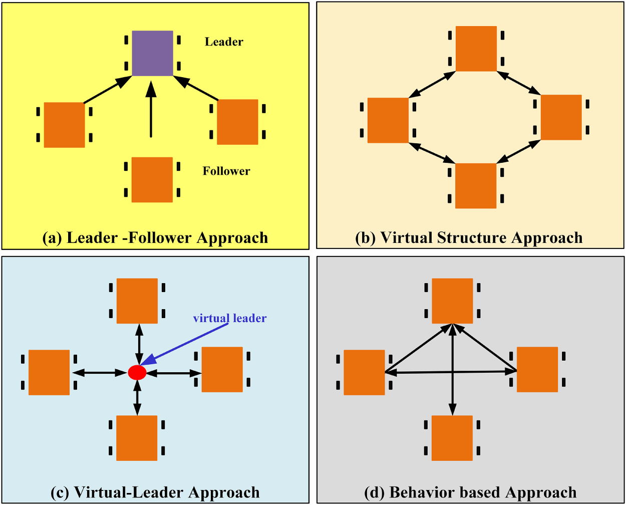
Figure 1: Formation control in unmanned ground vehicles.
Path planning plays an important role in the formation control of multiple unmanned vehicles, where every vehicle’s movement needs to determine its path from the starting position to the final destination, avoiding collisions with obstacles [9]. With the expansion of research and the increasing understanding of the surrounding environment through sensors, various path-planning algorithms have emerged for unmanned vehicles, including A* [10], RRT [11], PRM [12], and Hybrid A* [13]. These algorithms work in different scenarios of unmanned vehicles. However, in multiple vehicle formation control, the group of vehicles needs to avoid obstacles while they are moving towards their final destination, which is a complex process [9]. Because all the vehicles should move as a group to maintain the safety distance between each other, find the shortest path towards the final destination, and avoid collision with the obstacles while in motion. Fig. 2 shows the path planning of vehicles, where Fig. 2a represents the path planning of a single vehicle and Fig. 2b shows the path planning of multiple vehicles in a group.
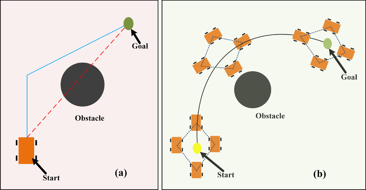
Figure 2: Visualization of path planning technique (a) Path planning of a single vehicle, (b) path planning of multiple vehicles as a group.
Formation control in Unmanned Ground Vehicles (UGVs) presents significant challenges in collaboration, path planning, and collision avoidance, especially in dynamic environments [6]. Most existing studies address collision avoidance with a single static obstacle, assuming known obstacle positions. However, real-world scenarios involve unknown and moving obstacles, making coordinated movement more complex. Path planning for multiple UGVs often focuses on individual optimization, neglecting formation constraints, which can lead to inefficient paths and inter-vehicle collisions [14]. Distributed formation control offers greater flexibility by allowing local decision-making based on real-time feedback, but maintaining coordination and obstacle avoidance in a decentralized setting remains difficult due to communication limitations and computational complexity [7].
This research aims to address these challenges by developing a virtual leader-based formation control strategy integrated with an improved A* path planning algorithm, enhancing real-time adaptability, formation stability, and collision avoidance in cluttered environments with static obstacles and inter-agent dynamics. In this research, we proposed DFCOA, a distributed formation control and obstacle avoidance of a multi-UGV system using a virtual leader and an improved A* algorithm, which will plan the path of the virtual leader by the improved A* algorithm, and other group members will negotiate their positions to maintain the group structure shown in Fig. 3. In this proposed research, we have utilized the VFH* and repulsive force function with a 2D LiDAR sensor to determine the position of obstacles and adjust the trajectory, thereby maintaining the formation. The contributions of this study are as follows:
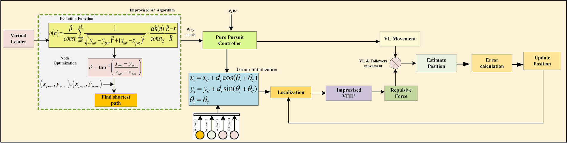
Figure 3: The proposed DFCOA architecture in this research paper.
1. An integrated distributed formation control and obstacle avoidance framework (DFCOA) for multi-UGV systems in cluttered environments, which simultaneously addresses global path planning, formation maintenance, and multi-agent collision avoidance—a combination not fully resolved in existing distributed approaches. Experimental results demonstrate high formation stability of 95.8% in a dense obstacle scenario and 94.6% under external disturbance, with low formation centroid errors (0.9516 and 1.0008 m RMS, respectively).
2. An improved A* path planning algorithm with a novel cost function that penalizes proximity to obstacles and optimizes node expansion, reducing average computational time by
3. An enhanced VFH* obstacle avoidance method incorporating inter-agent repulsive forces, which enables UGVs to avoid collisions with the obstacles while actively maintaining safe inter-vehicle distances.
4. A virtual-leader-based coordination structure that ensures scalability and robustness without single-point failure vulnerability, enabling precise velocity tracking with velocity centroid errors of 0.2699 and 0.1700 m/s RMS, closely matching the desired velocity of 0.3 m/s in two experimental scenarios.
5. Comprehensive quantitative validation and comparative analysis demonstrating that DFCOA outperforms established published research papers.
The remainder of this paper is organized as follows. Section 2 presents a comprehensive review of the recent literature on multiple UGV formation control, path planning, and obstacle avoidance strategies. In Section 3, the problem formulation is described in detail, including the mathematical modeling of UGV kinematics and the definition of the formation control objectives with the definition of the performance metrics. The proposed methodology is elaborated in Section 4, where we introduce an improved A* path planning algorithm, a virtual leader (VL)-based formation framework, an improved VFH* obstacle avoidance algorithm, and a mechanism for estimating positional deviations. Section 5 provides experimental results that validate the effectiveness and robustness of the proposed approach. In the end, Section 6 concludes the paper and discusses potential directions for future work in UGV formation control research.
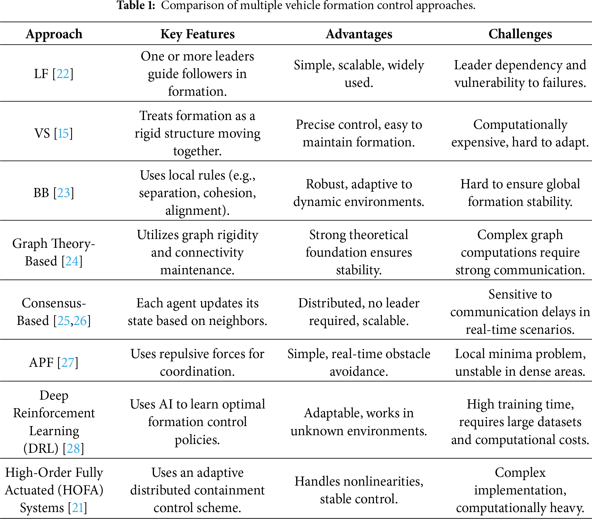
The newer developments in multi-agent systems have seen major improvements in the areas of formation control that enabled multi-UGV path planning and obstacle avoidance. However, the new challenges of scaling and complex conditions, and constraints remain as critical issues in the combination of such components. The contemporary formation control policies focus on decentralization to increase scalability and strength [15]. Early methods, e.g., virtual structures, were based on focusing on global trajectory tracking, yet they did not cope well with dynamical settings [8]. Computational bottlenecks were reduced with leader-follower methods, but single-point failure threats were created. Recently, ref. [16] has developed a work of decentralized control by uniting collision avoidance with connectivity maintenance, but their approach presupposes the existence of perfect localization, which was mentioned in [17] in 2013. There is a new paradigm of adaptive coordination in deep reinforcement learning (DRL). In [18], Tan and Bejarano from the University of Toronto used DRL to control heterogeneous mobile robots in formation, with the resulting methods demonstrating less than a meter tracking errors in simulations. Nevertheless, their framework is not integrated with global path planners, which limits its use in obstacle-filled environments. The survey on the formation control of swarm robotics trends by [19] revealed a strong gap with very few studies on simultaneous formation control, obstacle avoidance, and localization in the context of sensor noise. Table 1 compares multiple UGV formation control approaches with the recent High-Order Fully Actuated (HOFA) [20] in formation control, which can handle the nonlinearities of multiple agents with the advanced control technique, but the complex implementations and the high computational costs make it less efficient [21].
The A algorithm* remains a cornerstone of grid-based planning due to its optimality guarantees. Recent innovations focus on enhancing efficiency and adaptability. Han et al. [29] proposed a hybrid A* variant for unmanned vehicles, combining heuristic search with motion primitives to generate smoother paths in structured environments. Wang et al. [30] introduced adaptive A*, dynamically adjusting heuristic weights for real-time performance in dynamic grids, and in [31], used the evaluation function with the optimized node for the multi-vehicle path planning [32]. While these methods reduce computation time by 30%–40%, they do not account for multi-agent formation geometries. Sampling-based planners like RRT* or probabilistic road-maps(PRM) [33] excel in high-dimensional spaces but generate jerky trajectories unsuitable for UGVs. DFCOA bridges this gap through an improved A* algorithm that prioritizes diagonal movements and penalizes proximity to obstacles, enabling formation-aware global planning with less computational time with optimizing the number of nodes and the path distance [31] as shown in the binary map in Fig. 4.
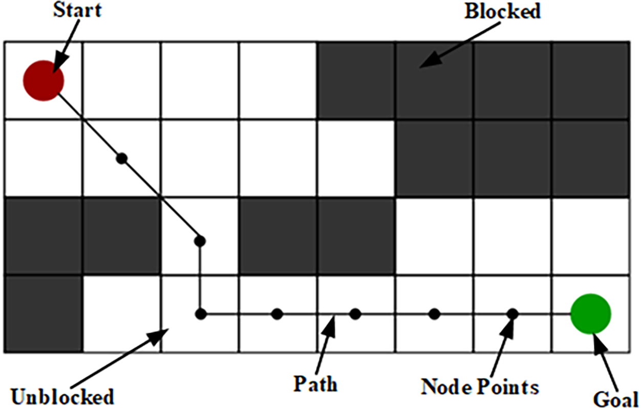
Figure 4: Path planning in the binary map.
Local obstacle avoidance techniques must balance reactivity and stability of the group of multiple vehicles. The Vector Field Histogram (VFH) [34] remains widely adopted for its computational efficiency, but its reliance on accurate localization limits performance in GPS-denied settings. Researchers [35] enhanced VFH with probabilistic steering (VFH*) [36], reducing oscillations in narrow passages by 25% for Unmanned Surface Vessel. Zhao et al. [37] integrated reinforcement learning with LiDAR data for dynamic obstacle avoidance, achieving 89% success rates in pedestrian-rich simulations where While learning-based methods show promise, they demand extensive training data and lack interpretability [37,38]. Accurate localization is critical for both formation control and obstacle avoidance. LiDAR-inertial odometry has advanced GPS-denied navigation [39], achieving centimeter-level accuracy in structured environments. Collaborative SLAM frameworks [40] enable multi-UGV map fusion but incur high communication overhead. Ullah et al. [41] surveyed mobile robots localization and described Monte Carlo localization (MCL) advancements, demonstrating its robustness under sensor noise but noting scalability challenges in dense formations [42].
Although significant advances have been achieved in the area of multi-UGV coordination, there are still a number of serious gaps to be taken into account in terms of the integrated formation control and obstacle avoidance in dynamic and cluttered environments. The merits of existing approaches are simplicity and scalability of leader-follower (LF) approaches [22], the high control of geometry provided by virtual structures (VS) [15], the resilience of behavior-based (BB) [23] approaches in the context of unknown conditions, and the theoretical assurance of consensus-based approaches [25,26]. Sampling-based planners (e.g., PRM, RRT*) perform well in high-dimensional spaces, whereas optimized variants of A* are more efficient in computational terms in a static grid [43].
Nevertheless, there are still significant weaknesses where LF methods are susceptible to a single-point failure, VS and graph-based methods lack real-time flexibility, APF methods are prone to local minima, and behavior-based methods cannot guarantee global formation robustness [1]. Moreover, the majority of the learning-related approaches (e.g., DRL) need a large amount of training data and are not interpretable [7,37]. The most glaring gap is the lack of integration between global optimal planning, distributed formation stability, and real-time multi-agent collision avoidance into a single, scalable framework. These aspects are frequently treated separately by existing systems, e.g., formation constraints when planning, reactive avoidance when forming globally, and result in poor performance in cluttered environments [44]. Such a disparity has inspired the suggested DFCOA structure, where global planning through a better A* path planning algorithm is combined with distributed formation control through a virtual leader and a real-time collision-avoiding algorithm by repulsive-force-based improved VFH* in one architecture.
The paper used four mobile robotic models here as the UGV model for distributed formation control and obstacle avoidance(DFCOA). Fig. 5 shows the kinematic model, which has two actuated wheels connected with the controller and a castor wheel that helps to turn the vehicle at the shortest angle.
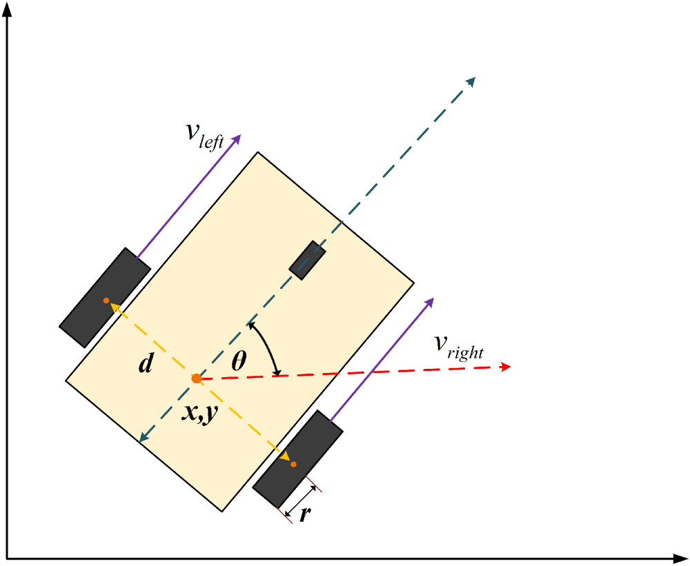
Figure 5: Kinematic modeling of the differential drive unmanned Ground Vehicle (UGV).
The
3.2 Formation Definition and Position Initialization
In this virtual leader(VL) based formation control technique, it is very important to initialize the position of the virtual leader and the group of UGVs shown in Fig. 6. Let’s the virtual leader of the formation represented by
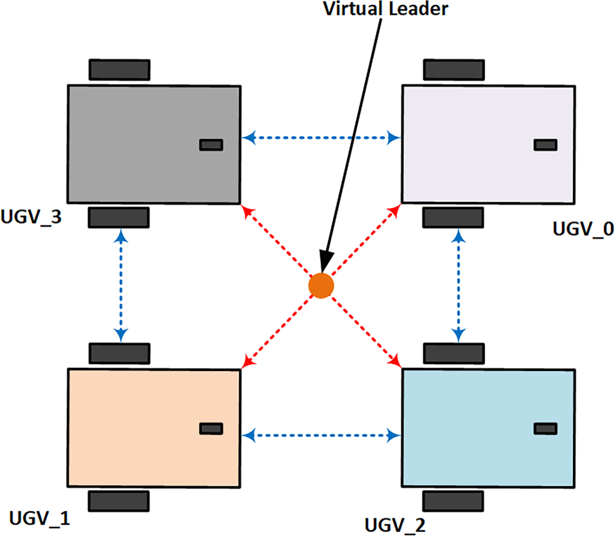
Figure 6: Geometric relationship between virtual leader (VL) and UGV’s in the formation group.
The initial position of the UGV can be determined by Eq. (4) where
To form the rectangle of the UGVS with VL, it used Eq. (5), which represents the initial position of
This mathematical formulation clearly defines how the UGVs are initially placed around the virtual leader in a rectangular formation.
3.3 Performance Metrics Definition
To quantitatively evaluate the performance of formation control, stability, safety, and motion quality of the proposed DFCOA system, the following performance metrics are defined by Lyapunov stability theory, shown in [45]. These metrics provide a comprehensive assessment framework that encompasses the collision risk, formation centroid errors, formation shape errors, and velocity centroid errors. Formation Centroid Error (FCE), which is also known as tracking error, quantifies the deviation between the actual and desired formation centroids, representing the global translation error of the entire formation as shown in Eq. (6).
where
Formation Shape Error (FSE) evaluates the preservation of the relative geometric structure among UGVs, independent of the formation’s absolute position, where
The Formation Stability Error (FStE) characterizes the temporal consistency of formation maintenance by computing the moving average of centroid error over a specified time window T shown in Eq. (8). This metric reflects the system’s ability to maintain stable formation over time and indicates the stability of the formation group [47].
Eq. (9) indicates the Velocity Centroid Error (VCE) which assesses the alignment between the actual and desired collective motion of the formation group, where
Lower RMS values indicate smoother motion with fewer abrupt accelerations or decelerations, which is crucial for energy efficiency and mechanical wear reduction. Collision Risk Metric (CRM) provides a comprehensive safety assessment by evaluating both inter-vehicle and vehicle-obstacle proximity risks while the vehicles are moving [47].
In Eq. (11),
By following the proposed system architecture of the proposed DFCOA in Fig. 3, the proposed methodology outlined in four parts, the path planning by the improved A* algorithm, the virtual leader based formation structure, the improved VFH* approached-based collision avoidance with inter agent repulsive force to keep the group of vehicles together, the position estimation and the movement which will lead the group followers with the virtual leader to the goal position.
4.1 Improved A* Based Path Planning
The proposed DFCOA used the improved A* path planning algorithm by optimizing nodes and the path evolution function [31,49], which was published earlier, to plan the path in the binary map from the starting position to the goal destination. The research paper used the path planning approach for a single mobile robot; in this research, we used it for four UGVs with the virtual leader. The method used the evolution function
In Eq. (12),
where Eq. (13) shows the updated cost function, where
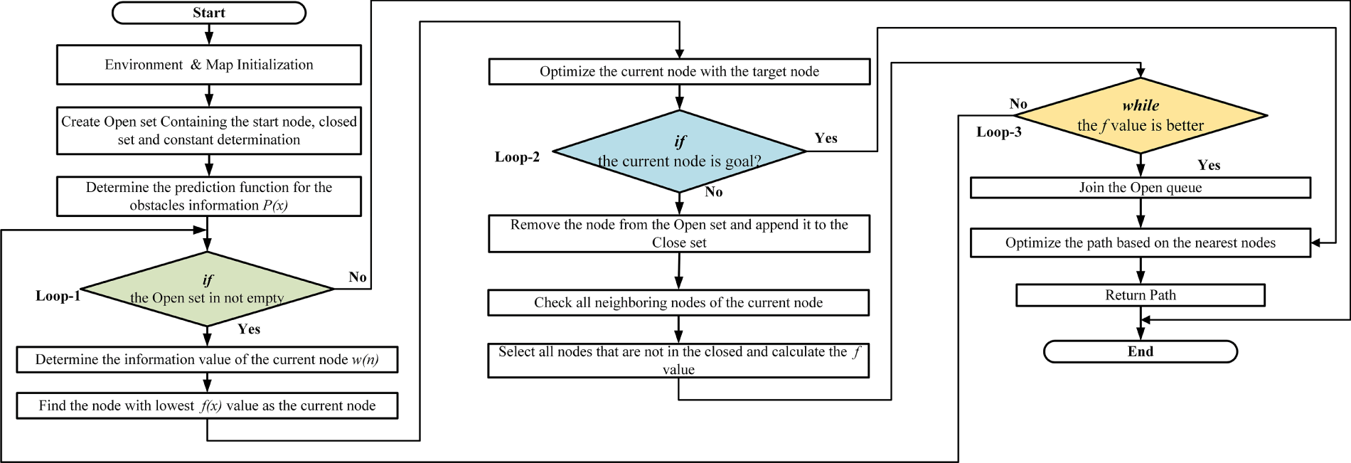
Figure 7: Flowchart of the improved A* algorithm [31].
4.2 Virtual Leader Based Formation Structure
The virtual leader-based formation structure shows the relation between the virtual leader with the follower UGVs while all of them are moving. when the virtual leader defines the obstacle-free path by the improved A* path planning algorithm, the UGVs move together towards the goal shown in Fig. 8.
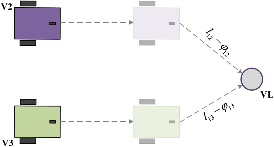
Figure 8: Constraints between the Virtual leader and group vehicles to maintain the group.
The determination of this VL-based formation control approach, the constraints relation between the VL and the follower shown in Fig. 8, where it defines the correlation between V2, V3, and VL. The distance and the angle constraints can be written as
We can consider the changes in the length of the follower based on the value of
This geometric framework simplifies the problem by establishing a coordinate system with the virtual center as the origin of Fig. 6, thus specifying the coordinates of the target position of the followers. The subsequent step involves computing the actual position of the Agent in the virtual center coordinate system. Given the pose of the UGV in the world coordinate system
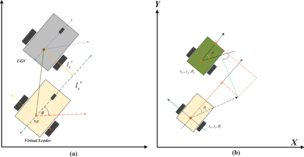
Figure 9: Coordinate position of the virtual leader (VL) and follower vehicles in the proposed method. (a) VL and follower center coordinate system, (b) Transformation of Coordinate Points based on the VL and followers.
Therefore, the error due to the positional changes in the leader-follower structure can be written as,
If the errors
If we write the equation in a simplified way,
From there, we can calculate the error
However,
If the derivative of
where
So, we can calculate the linear and the angular velocity from the above equation, where
4.3 Obstacle Avoidance Technique with Repulsive Force
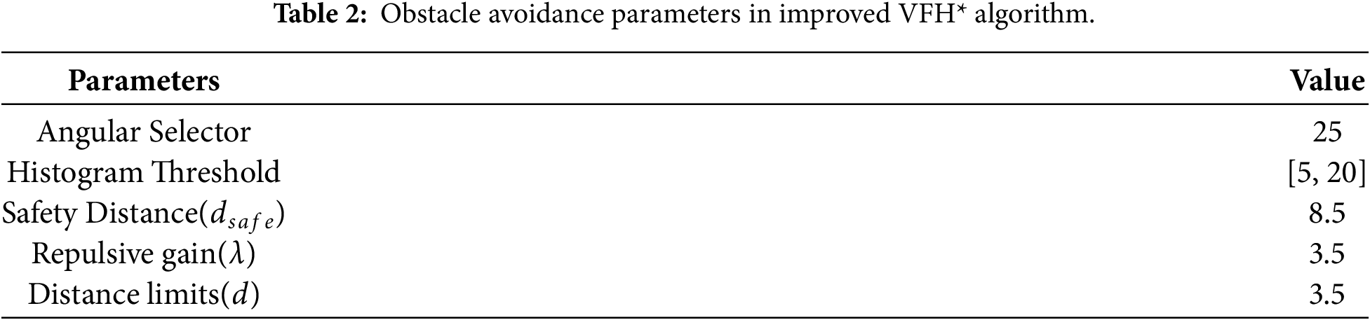
The proposed DFCO used the improved VFH* obstacle avoidance algorithm to avoid collisions with obstacles while vehicles moved towards the goal as a group. The proposed technique utilized a repulsive force to maintain the formation after the group members had avoided collisions with obstacles in their path, improving the traditional Vector Field Histogram (VFH*) algorithm. Fig. 10 shows the obstacle avoidance of the UGV group and the group reconstruction with the repulsive forces, which improves the VFH* algorithm [36] with the obstacle avoidance parameters mentioned in Table 2, which is an updated version of the traditional VFH algorithm [34] as shown in Fig. 10.
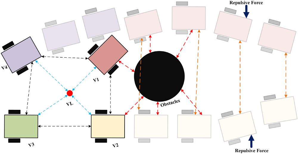
Figure 10: Obstacle avoidance of the group of UGVs and group reconstruction by the repulsive forces.
The Improved VFH* (Vector Field Histogram Star) algorithm is a local obstacle avoidance and motion planning strategy designed for autonomous navigation in multi-UGV’s which It extends the conventional VFH* by incorporating dynamic obstacle awareness through 2D LiDAR sensing and ensuring inter-agent safety via repulsive potential fields. For each of the four UGVs, the environmental geometry is first discretized into a polar histogram H, where each bin
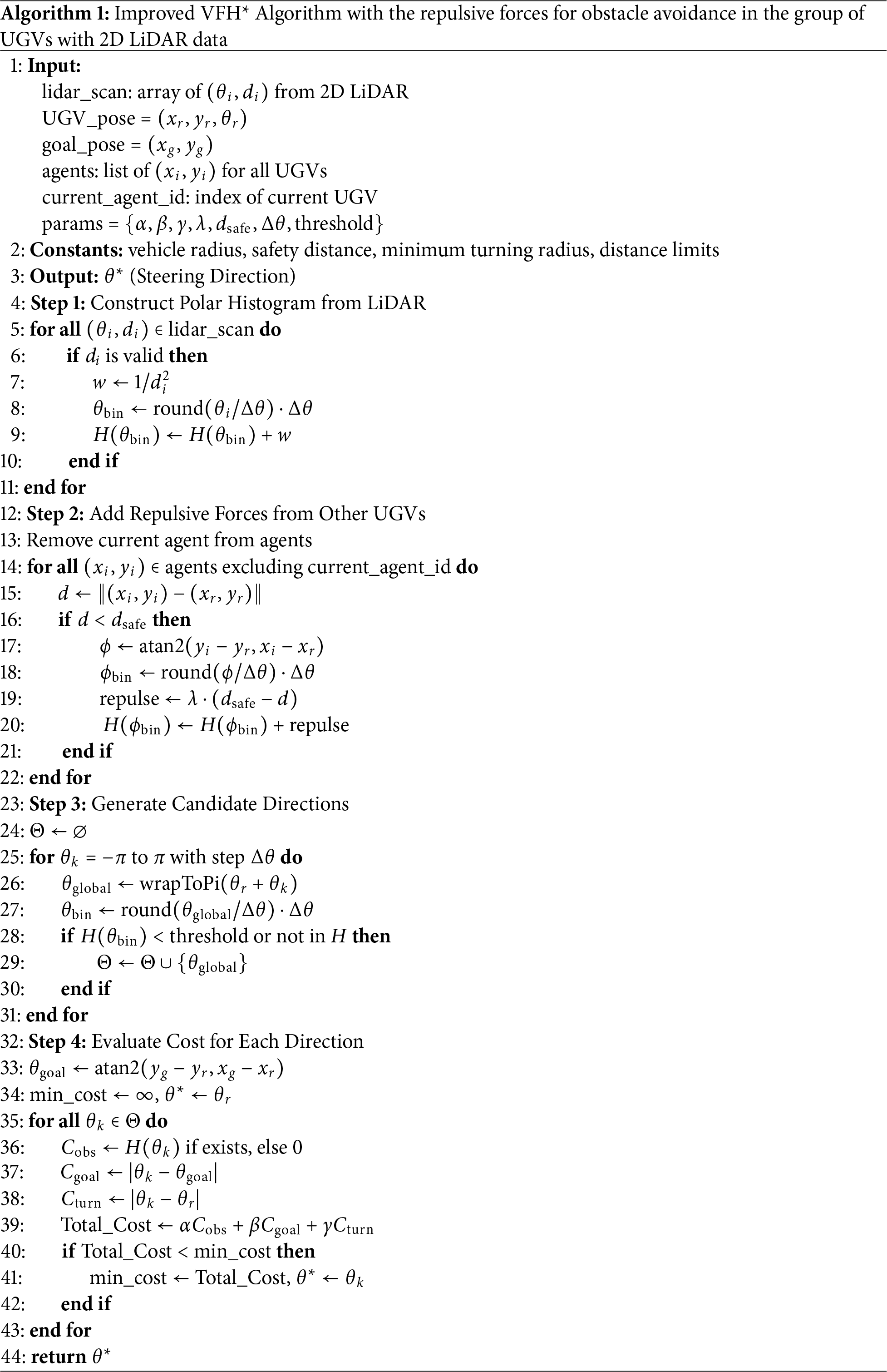
To facilitate multi-agent coordination, the algorithm incorporates inter-vehicle repulsive forces into the histogram. When a neighboring agent
where
4.4 Position Estimation and Movement Control
In the proposed DFCOA framework, maintaining a specified spatial configuration relative to a virtual leader is critical for ensuring coordinated motion. In Algorithm 2, the pose error computation technique addresses this by determining the deviation of each follower UGV from its ideal geometric position. Let the virtual leader’s pose be represented as
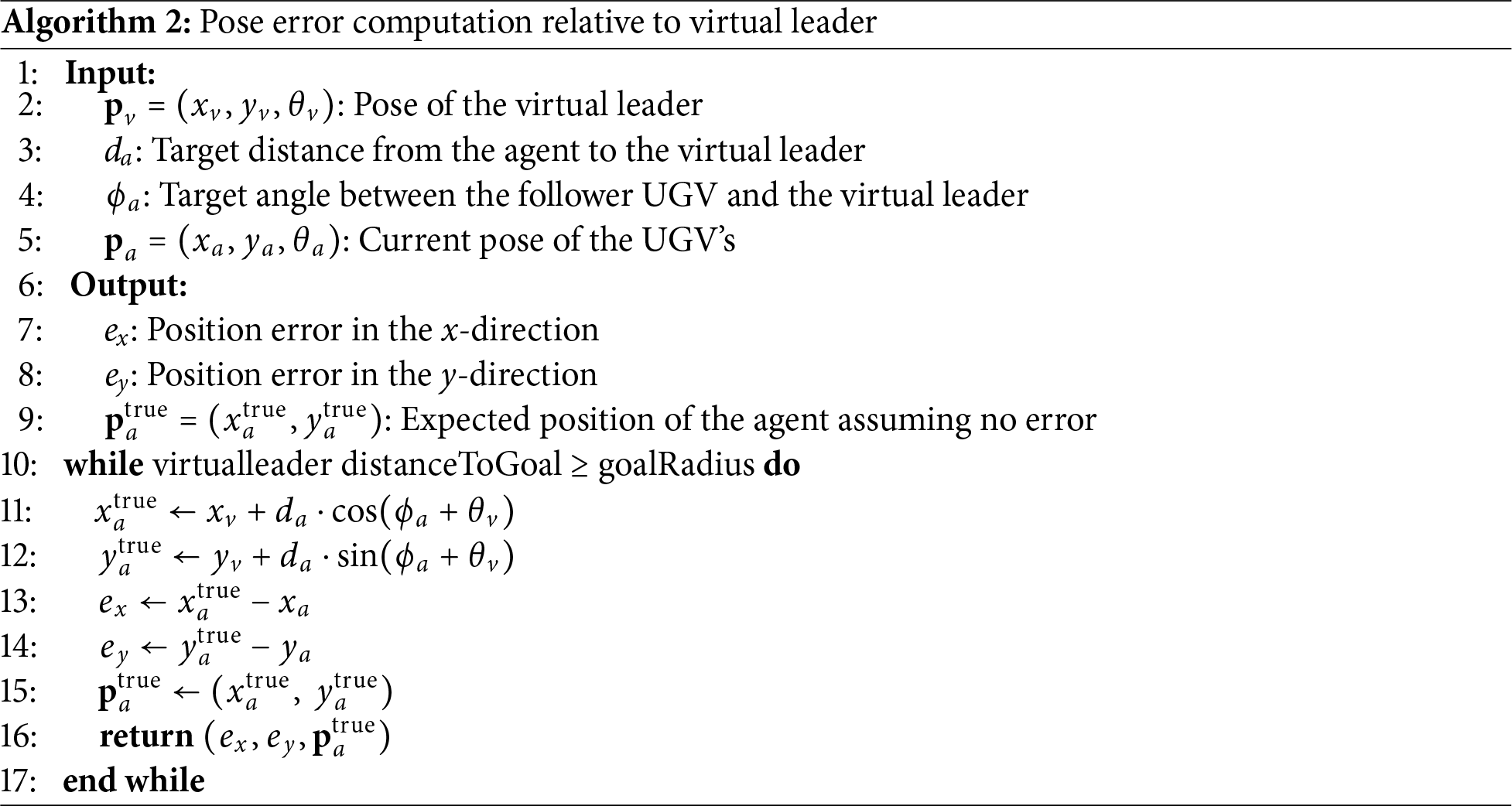
This predicted position represents the agent’s ideal location in a local coordinate frame aligned with the virtual leader. The current pose of the agent is given by
These errors,
4.5 Theoretical Integration of Components
The integration of the DFCOA approach plays an important role in maintaining the formation group of UGVs. The DFCOA framework integrates three theoretical pillars into a cohesive distributed control system, the virtual leader’s trajectory generation(actual path) by the improvised A* path planning algorithm, stabilizing the formation group by the Lyapunov Stability analysis, and the obstacle avoidance as a safety filter, which finds the reactive safety layer from Algorithm 1, measuring the inter-vehicle safety distance.
4.5.1 Virtual Leader as a Reference Generator
The virtual leader provides a stable reference trajectory
4.5.2 Distributed Formation Control via Lyapunov Stability
The formation control law derived in Eqs. (26)–(28) is designed using Lyapunov’s direct method. By defining the error dynamics in Eqs. (16)–(19) and selecting the control inputs
This guarantees asymptotic stability of the formation tracking error in the absence of obstacles.
4.5.3 Obstacle Avoidance as a Safety Filter
The improved VFH* with repulsive forces (Algorithm 1) acts as a reactive safety layer. It can be interpreted as adding a repulsive potential field
The gradient of this field generates corrective velocities that temporarily override the formation control commands when collisions are imminent, ensuring safety takes precedence over formation accuracy.
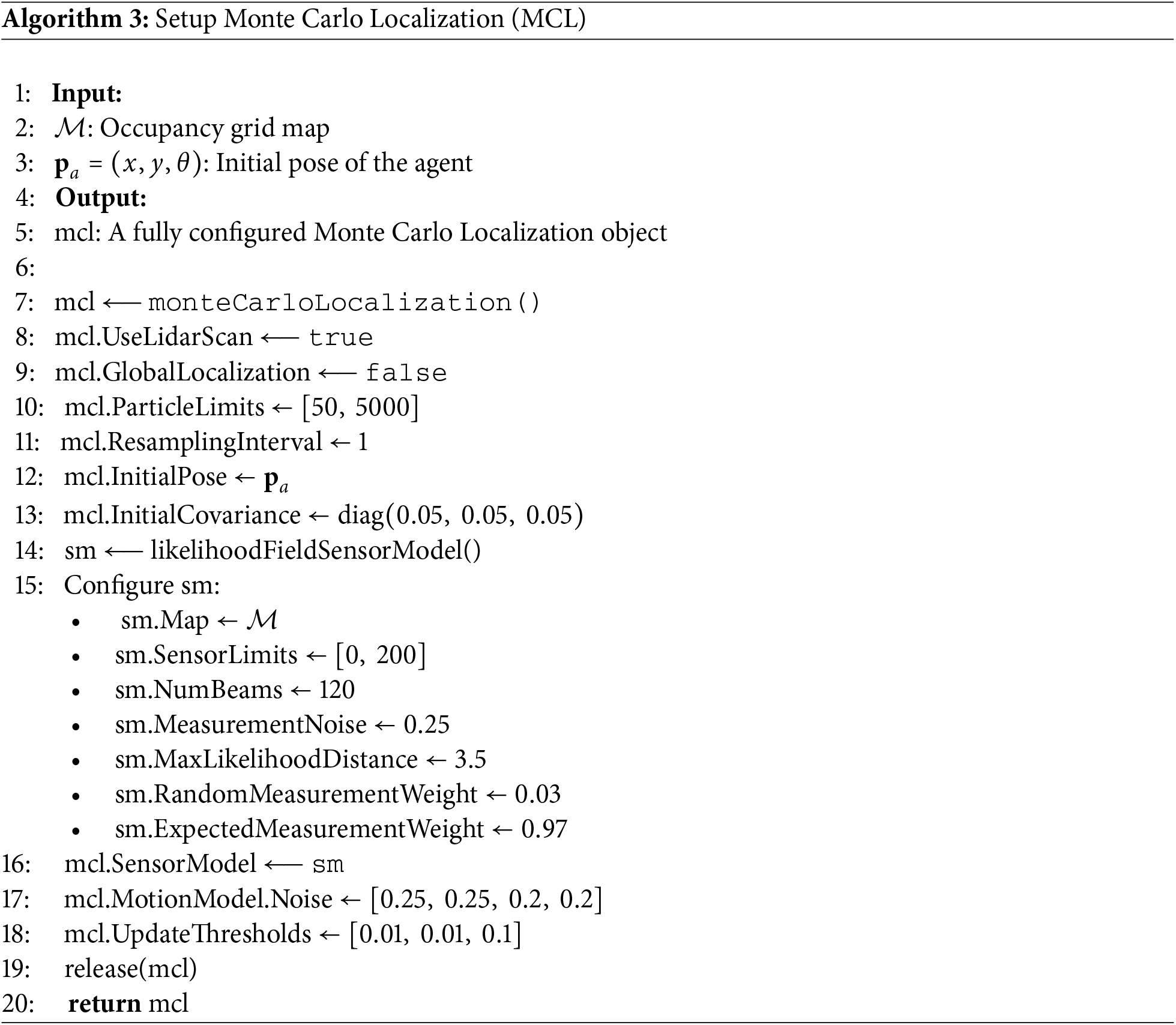
The DFCOA framework is fundamentally architected as a distributed system, ensuring each UGV operates autonomously based on the available information. This is achieved by deploying identical instances of the core algorithms that comprise the improved VFH* algorithm with repulsive forces (Algorithm 1), the pose error computation relative to the virtual leader (Algorithm 2), and the Monte Carlo Localization (Algorithm 3) on each vehicle. Consequently, no central coordinating agent is required in this system. Each UGV relies solely on its own 2D LiDAR scans for perceiving static obstacles and the positions of neighboring agents within its sensor range. The only shared information is the state of the virtual leader
In this section, numerical simulations are carried out to validate the performance of the proposed DFCOA for multiple UGVs. Besides, some comparisons with existing formation control schemes are presented. The proposed DFCOA system utilizes an Intel(R) Core(TM) i5-10400 CPU @ 2.90 GHz with a Windows 11 operating system. For the simulation platform, MATLAB R2024b with the Robotics toolbox, Localization and Navigation Toolbox was used, and the code was written in MATLAB scripts.
The proposed DFCOA was implemented in two experimental scenarios where four UGVs were connected with a virtual leader and planned their path, avoiding static obstacles using the improved A* algorithm, avoiding collisions using Algorithm 1, which utilized the improved VFH* Algorithm by repulsive forces to maintain the group of UGVs after avoiding the obstacle while moving as a group with Algorithms 2 and 3 with their virtual leader on a binary occupancy maps.
In Scenario 1, the DFCOA is evaluated in a binary map starting from the initial position (7, 6) to the goal position of (30, 12), where the other experimental parameters such as the desired velocity of UGV’s, look-ahead distance and the maximum angular velocity along with the control parameters of Scenario 1 are shown in Table 3. Fig. 11 shows the Output of the proposed DFCO approach in Scenario 1, where the movement of the UGVs with their virtual leader(VL) avoids the obstacles from the starting position to the goal destination. In Scenario 1, to make the task complex, it was decided to place the initial position obstacles, considering that the initial position surrounded by the obstacle will cause disturbance in planning the collision-free movement with the obstacles and the group of UGVs’s each other. By the proposed DFCOA approach, the method shows precise accuracy. The VL determines the shortest obstacle-free path from the starting position towards the goal position, and understanding the VL’s path, the group of UGVs/ Agents adjust their positions and maintain the safety distance with the VL and follower UGVs. The total experimental process of the scenario took 90 s, and for better explanation, we separate the whole experimental process into four parts, and they are, starting (
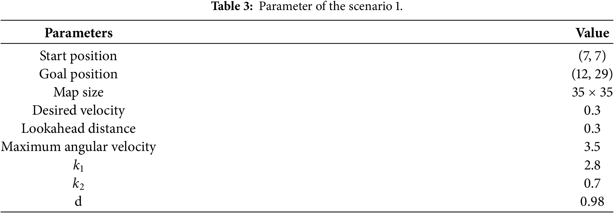
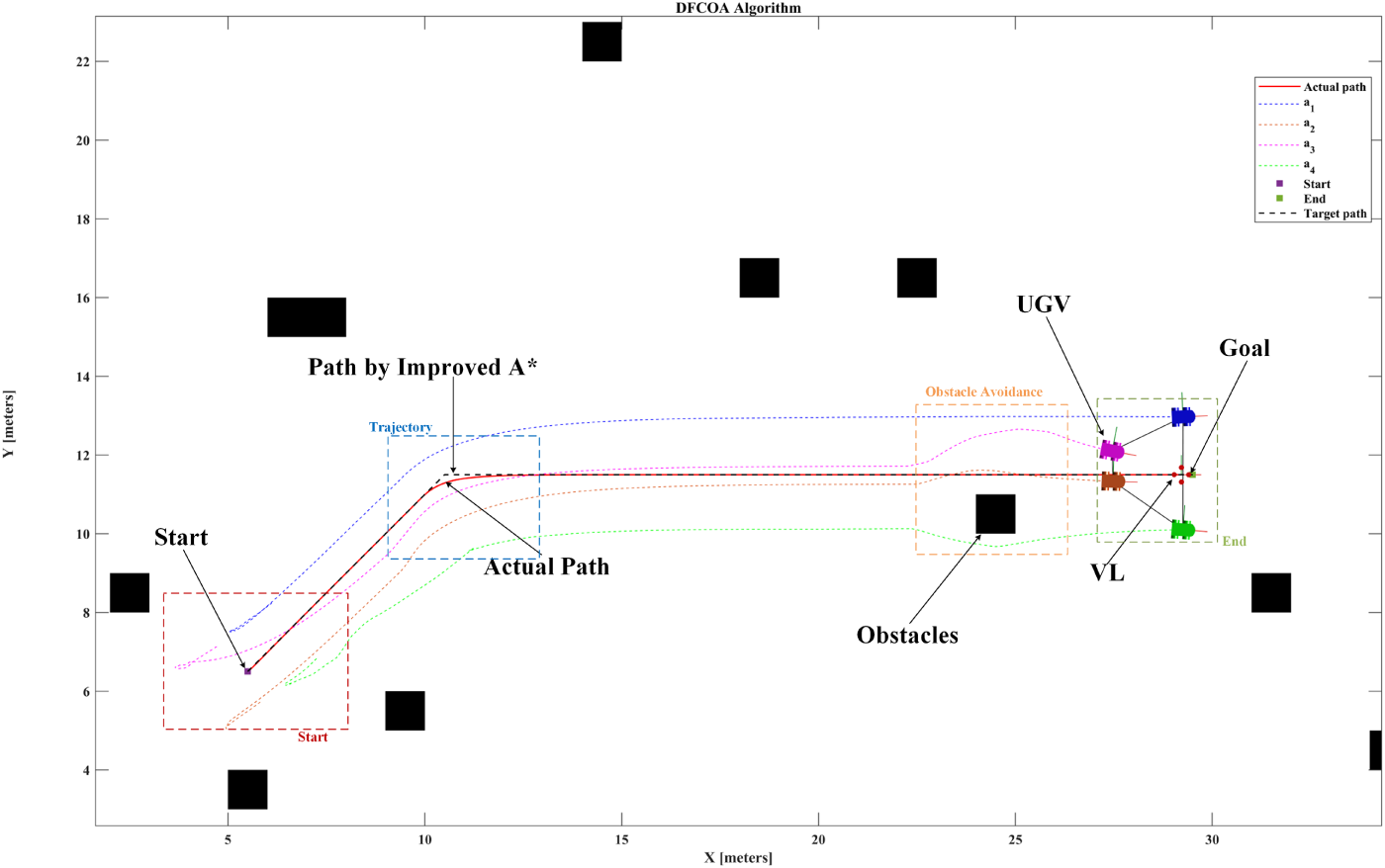
Figure 11: MAP of Scenario 1 with the VL and UGVs with the proposed DFCOA approach.
Figs. 12 and 13 illustrate the linear velocity, angular velocity,and the steering angles from the improved VFH* obstacle and collision avoidance algorithms output exhibited three distinct phases: starting, trajectory turning, and obstacle avoidance as shown in Fig. 11. During the initial period (
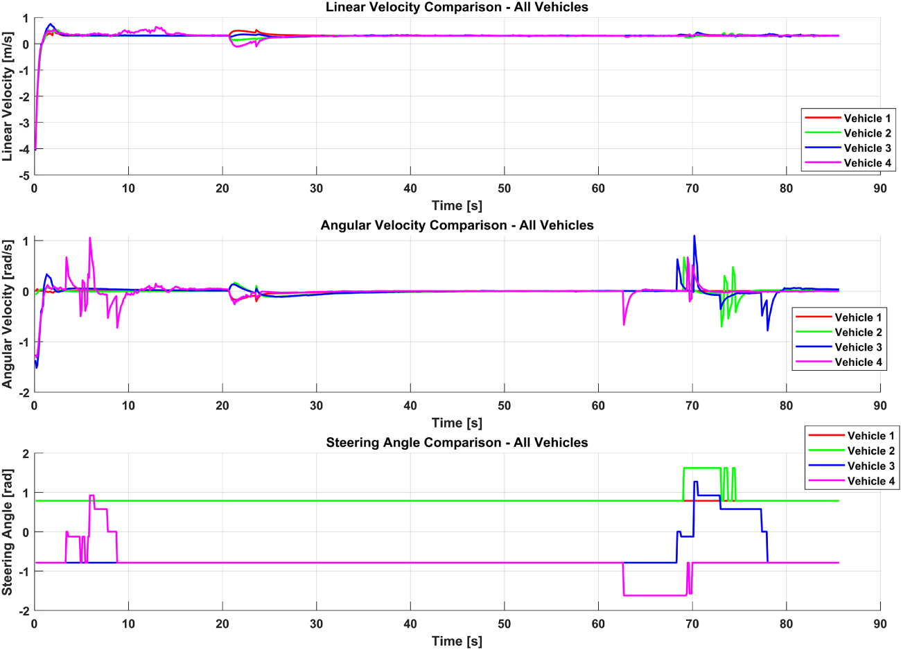
Figure 12: Performance of DFCOA in Scenario 1 with linear velocity, angular velocity, and steering angle of each vehicle.
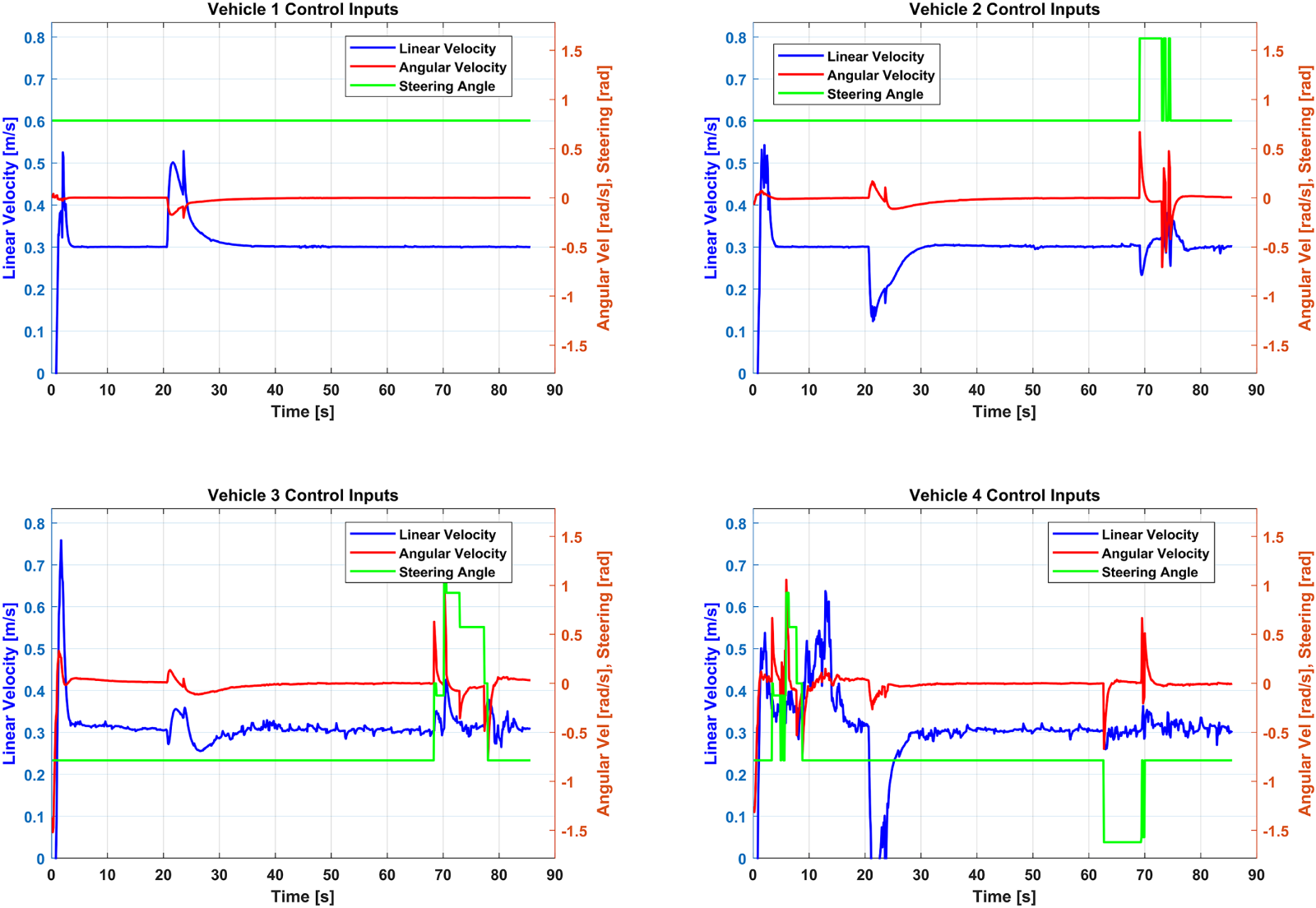
Figure 13: Individual vehicle control inputs by the DFCOA Approach in Scenario 1.
We also observed a similar response in the pose error graph in Fig. 14. In the X-Y-Axis pose error graph, the vehicle’s positional changes are observed due to starting and turning; from the figure, we can observe the response during the periods of obstacle avoidance (
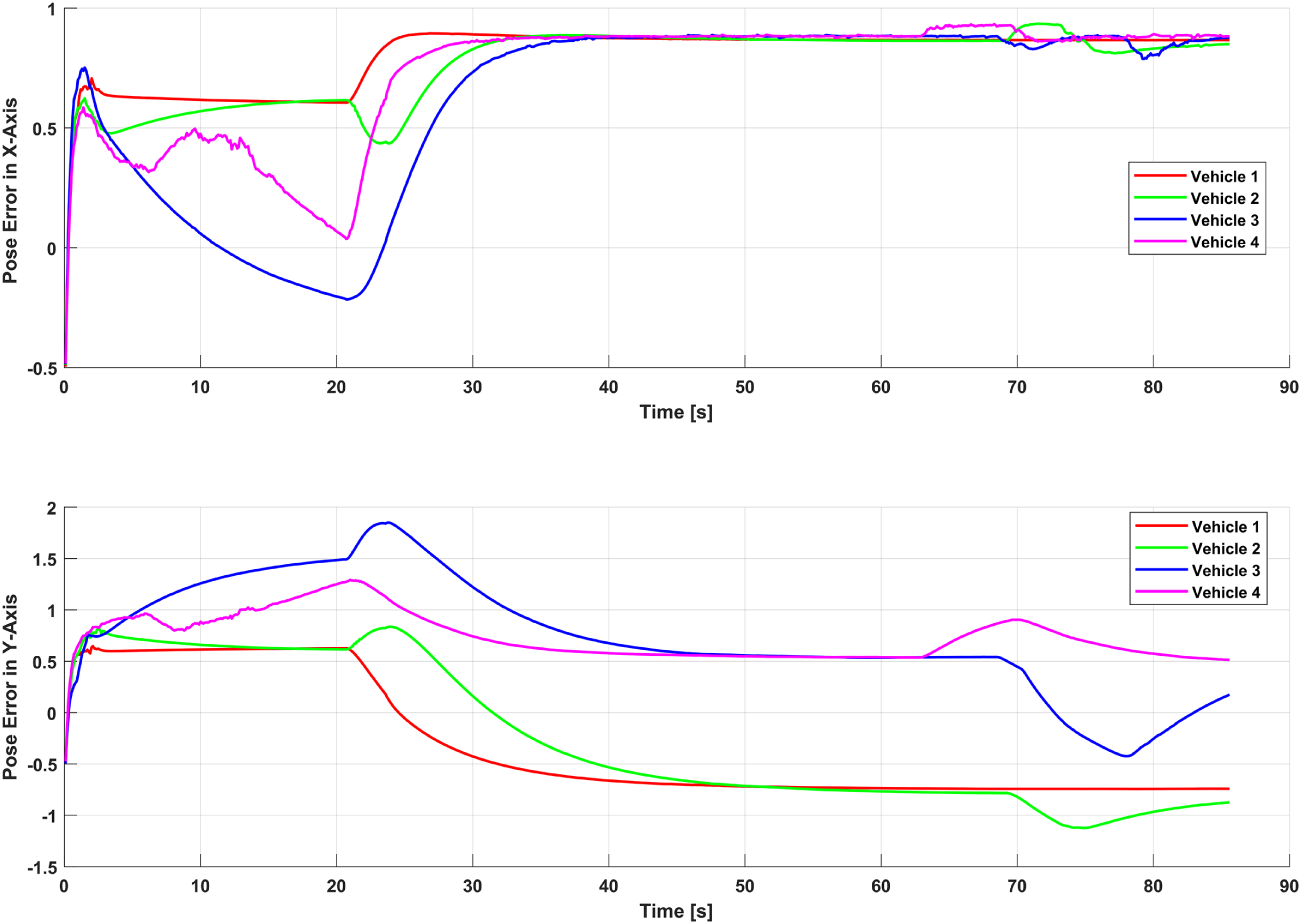
Figure 14: Pose error estimation by the proposed DFCOA in Scenario 1.
The proposed DFCOA framework was evaluated in Scenario 1, wherein four UGVs navigate from the starting point to the goal in a cluttered binary occupancy map. Quantitative results demonstrate robust performance in Fig. 15: the Formation Centroid Error (FCE) exhibits an RMS of 0.9516 m (mean 0.9486 m, max 1.1365 m) with longitudinal (X) and lateral (Y) components of 0.7880 and 0.5334 m, respectively, while the Formation Shape Error (FSE) records an RMS of 1.0511 m2, reflecting minimal geometric distortion during obstacle negotiation. Formation stability is maintained over 95.8% of the trajectory, confirming the virtual-leader-based control law’s cohesion. Velocity tracking is precise, with a Velocity Centroid Error RMS of 0.2699 m/s, an average RMS linear velocity of 0.3198 m/s—closely matching the desired 0.3 m/s—and a low average RMS angular velocity of 0.0539 rad/s, indicating smooth motion. Safety metrics show an average Collision Risk Metric of 0.7773, peaking transiently at 1.0 during critical avoidance phases, while the minimum inter-vehicle distance remains above the safety threshold at 0.4702 m, confirming collision-free operation.
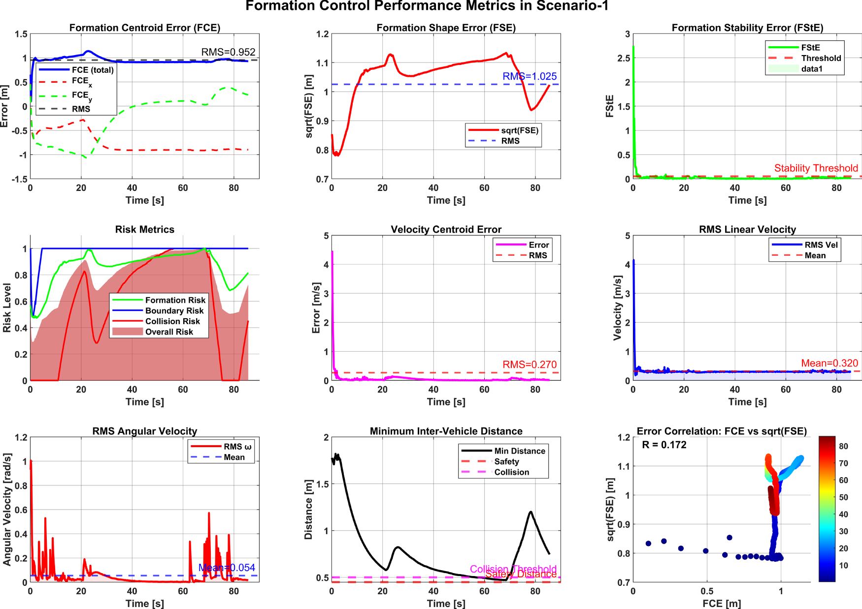
Figure 15: Formation control performance metrics of DFCOA in Scenario 1.
Collectively, these results validate the ability of the DFCOA framework to harmoniously balance formation accuracy, motion smoothness, and operational safety in a static-obstacle environment in Scenario 1. The observed centroid and shape errors (approximately 1 m) are deemed acceptable considering the map dimensions (35
In Scenario 2, the proposed DFCOA Approach was implemented again with four UGVs, where the UGVs plan their path by the improved A* approach from the starting position (31, 4) to the goal destination (20.55, 27) in the binary map with the disturbance in the
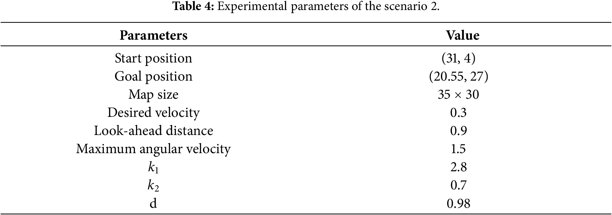
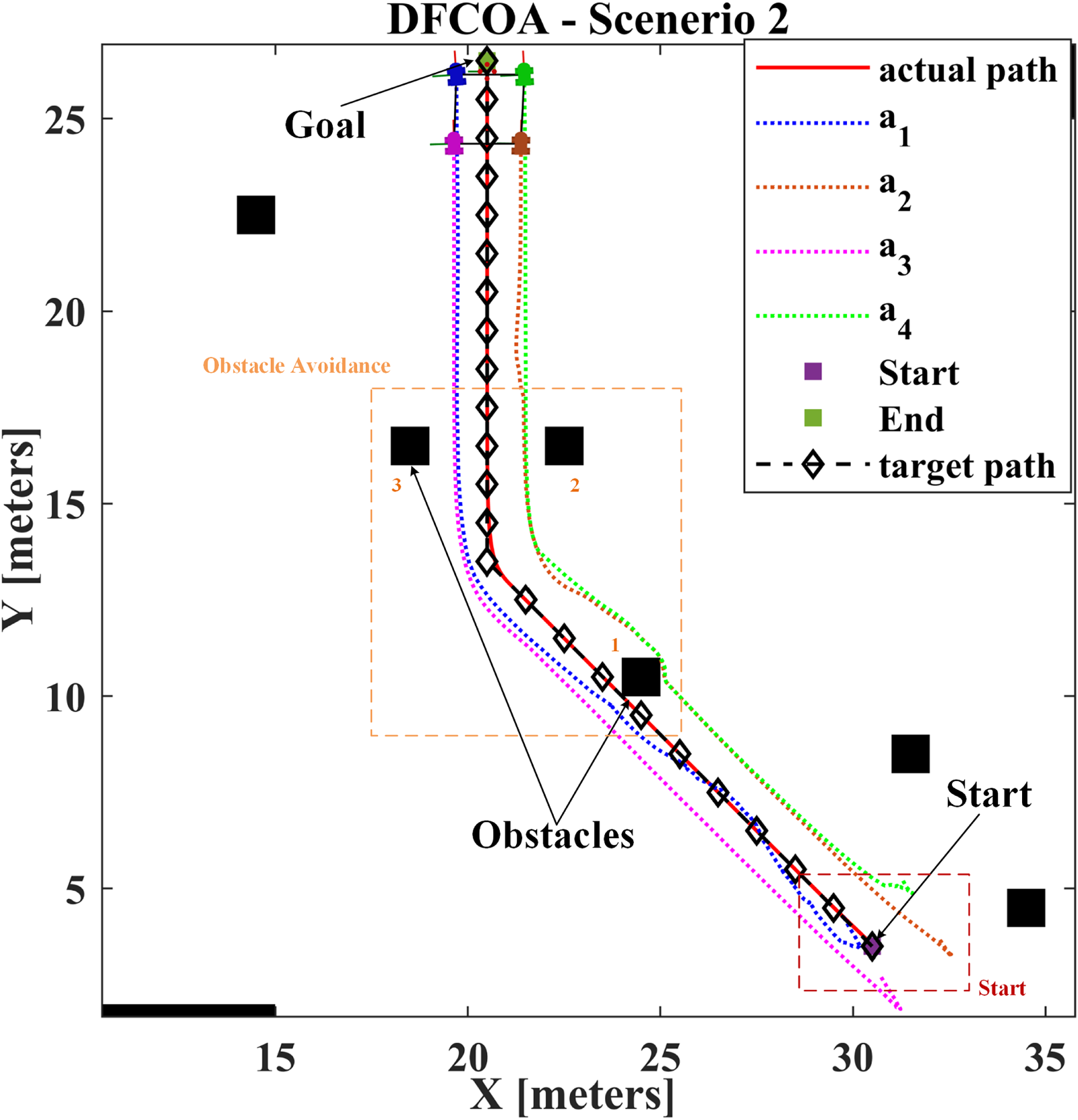
Figure 16: MAP of Scenario 2 with the VL and UGVs with the proposed DFCOA approach.
The total stimulation steps of Scenario 2 were separated into four parts based on the time period, as analyzed in Scenario 1, starting (
The robustness and dynamic performance of the proposed DFCOA framework are rigorously evaluated in Scenario 2, where the system’s response to an exogenous disturbance is analyzed alongside its performance across four distinct operational phases. As illustrated in Fig. 17 (aggregated velocity and steering profiles) and Fig. 18 (individual vehicle inputs), a deliberate disturbance applied to Vehicle 1(
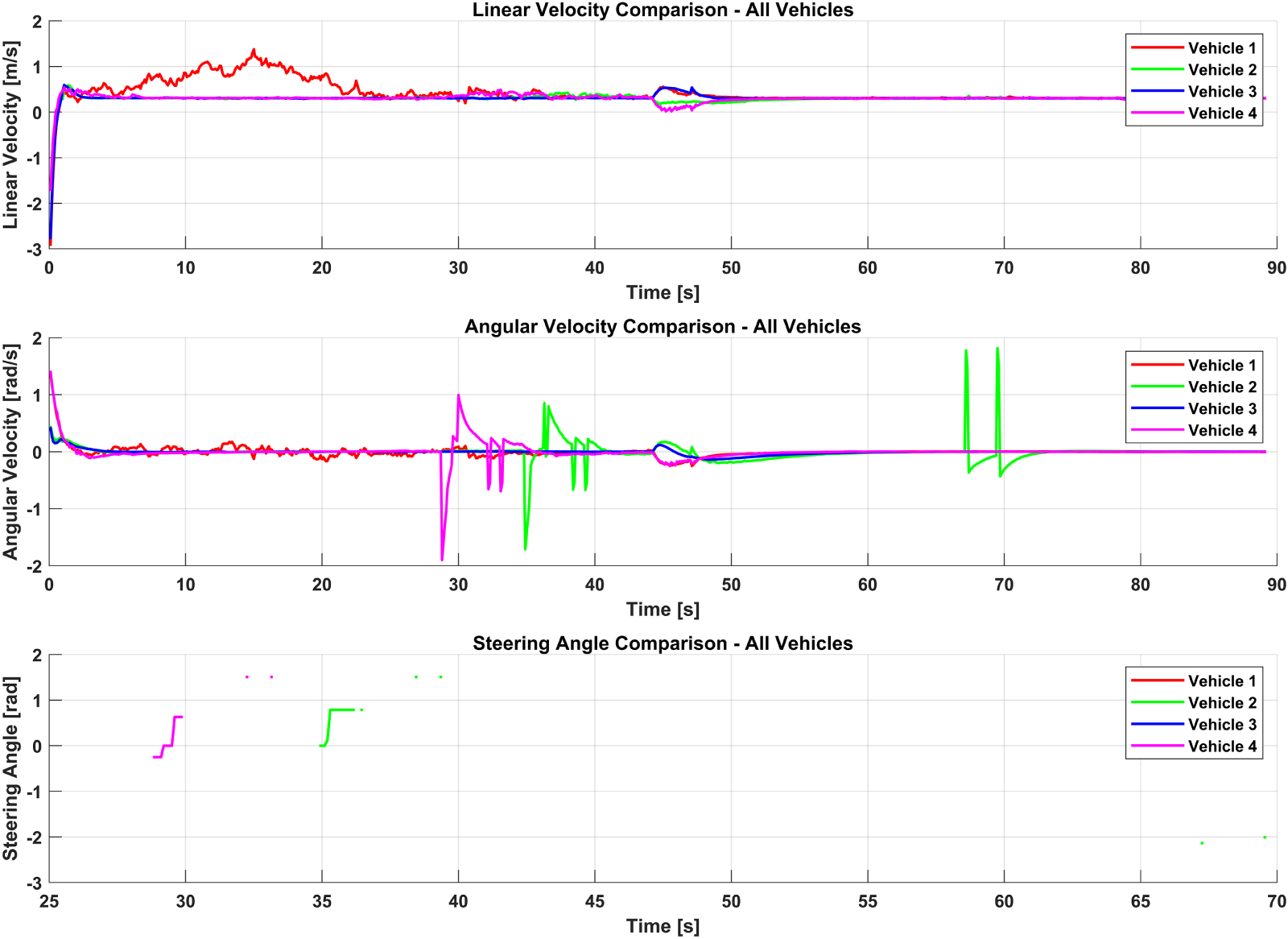
Figure 17: Performance of DFCOA in Scenario 2 with linear velocity, angular velocity, and steering angle of each vehicle.
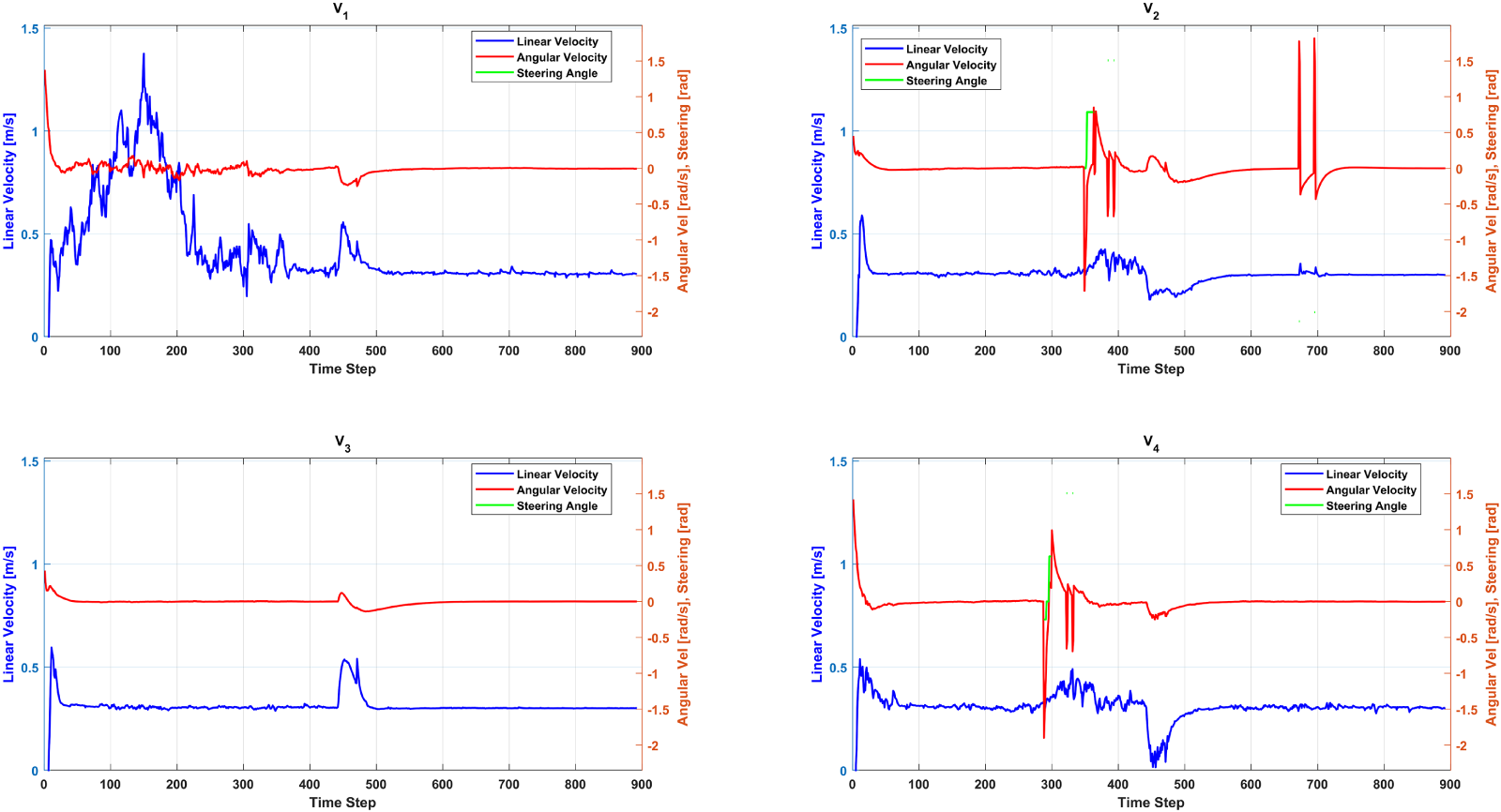
Figure 18: Linear velocity, angular velocity and the steering angle of the vehicles in Scenario 2.
During the subsequent obstacle-avoidance (
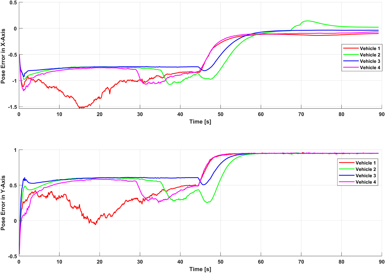
Figure 19: Pose error estimation by the proposed DFCOA in Scenario 2.
The performance of the proposed DFCOA framework in Scenario 2 is comprehensively quantified through the metrics presented in Fig. 20. The Formation Centroid Error (FCE) exhibits an RMS of 1.0008 m (mean 1.0002 m, max 1.1340 m), with longitudinal (X-Axis) and lateral (Y-Axis) components of 0.6648 and 0.7481 m, respectively, indicating balanced error distribution during the disturbance and obstacle-avoidance period (
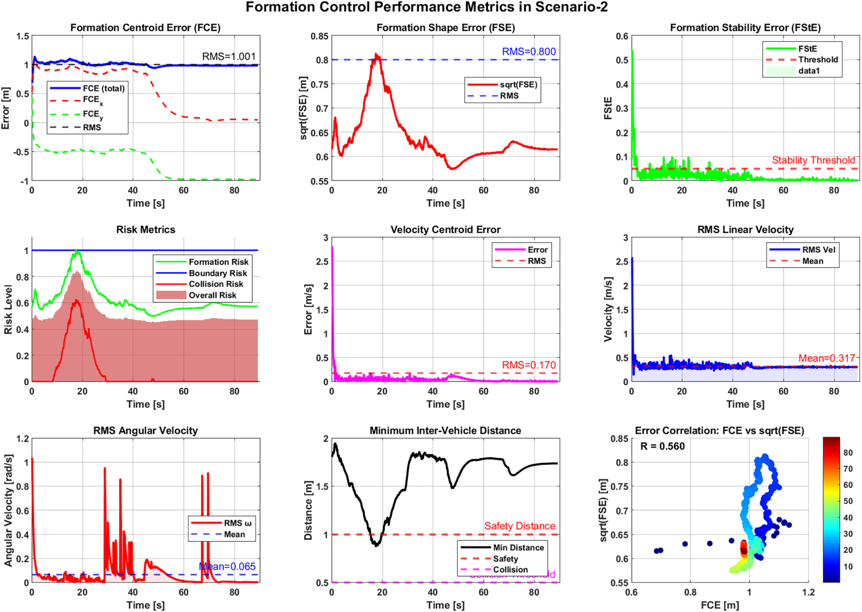
Figure 20: Formation control performance metrics of DFCOA in Scenario 2.
Table 5 shows the comparative performance metrics of the DFCOA in Scenarios 1 and Scenarios 2. Scenario 2—which introduced an exogenous disturbance and involved a more complex turning maneuver between obstacles—demonstrates the formation shape preservation (42% lower FSE) and velocity tracking precision (37% lower VCE) compared to Scenario 1. Although the centroid error increased marginally, the lateral (Y) component rose due to disturbance-induced corrections, while longitudinal (X) tracking improved. The risk metrics are substantially better in Scenario 2, with the average risk dropped by 34%, peak collision risk decreased by 38%, and the minimum safety distance nearly doubled. This indicates that the DFCOA framework not only maintains formation cohesion under disturbance but also proactively enhances safety margins during complex maneuvers. The slight reduction in formation stability (94.6% vs. 95.8%) is a reasonable trade-off given the added dynamic challenge. Overall, the results confirm that the integrated virtual-leader strategy, improved A* path planning, and repulsive force-based improved VFH* algorithm together provide robust, adaptive, and safe formation control in both static and dynamically perturbed environments.
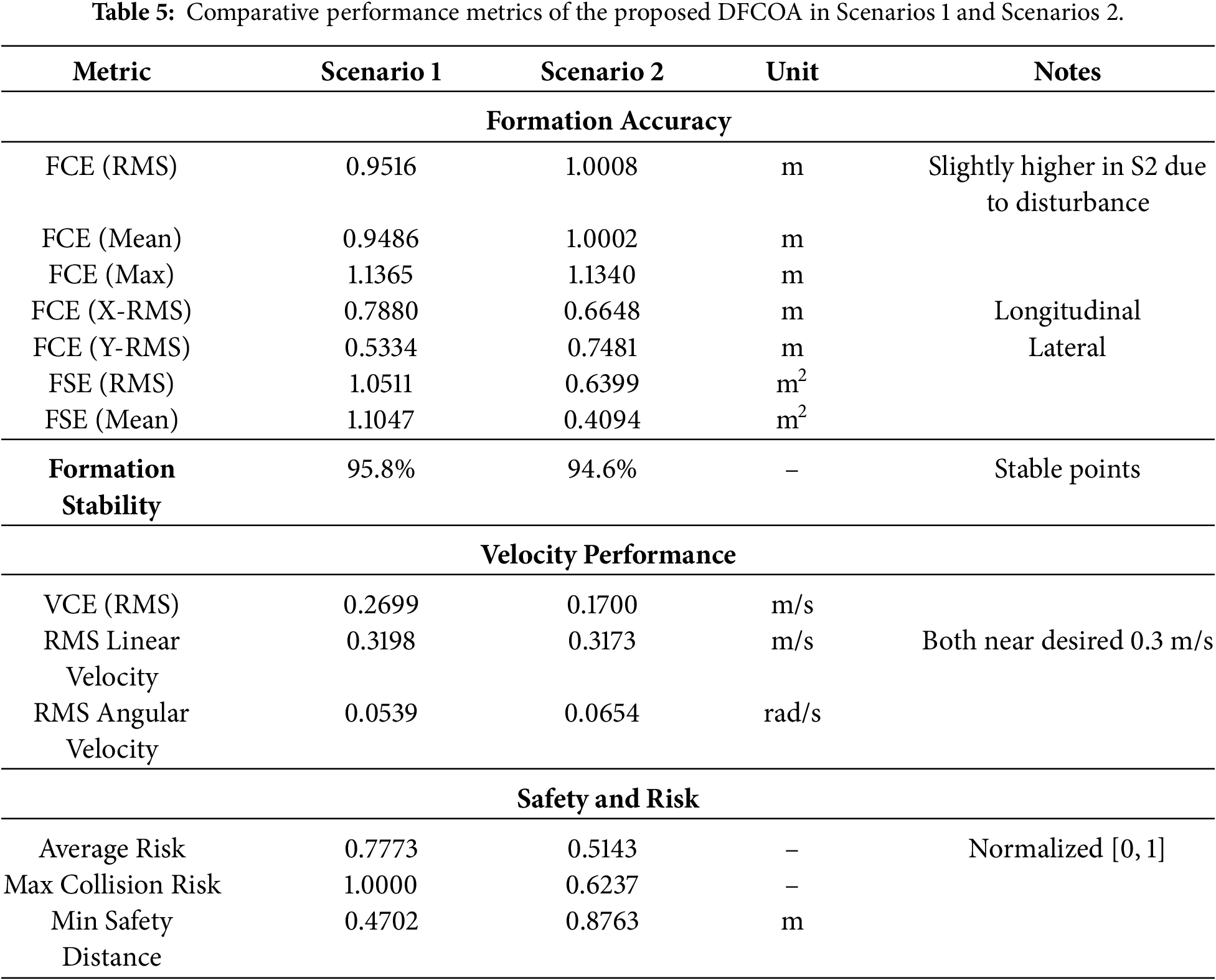
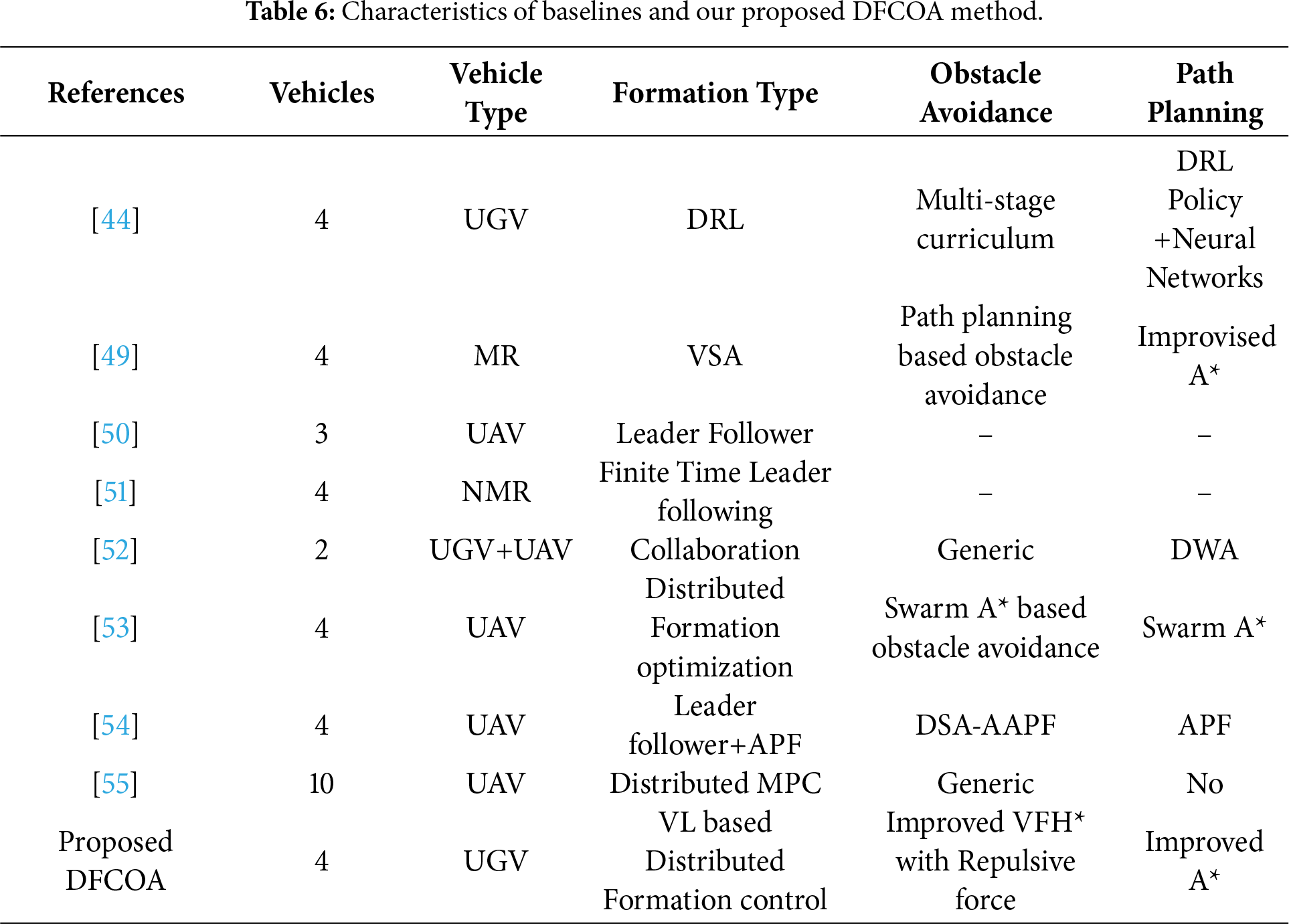
Table 6, as a comparative analysis, highlights the distinctive benefits of the suggested DFCOA framework in comparison with current formation control and obstacle avoidance methods. Earlier research on UAVs and nonholonomic mobile robots [50,51] had used leader-follower strategies and not integrated path planning and obstacle avoidance, limiting their use in cluttered environments. Techniques that used improvised A* path planning [49] enhanced the ability to generate global paths, but based on generic avoidance, making it very difficult to form stable structures. Hybrid aerial-ground teams used DWA-based local planning [52], but had problems with scalability, and swarm-based UAV teams provided distributed control and limited obstacle-handling [53–55]. In [44], authors found 95.83% in the multiple UGV collaboration in fighter fighting by the tailored neural network with the Deep reinforcement learning(DRL), where the training and testing took much time comparing other approaches in the Table 6. Ref. [54] enhanced the APF algorithm in four UAVs with the DSA-AAPF technique, where in a few cases, the formation stability and the formation centered error were very low while avoiding the obstacles. The proposed DFCOA, on the other hand, uses a virtual leader-based distributed structure, an improved A* algorithm to make efficient long-range path planning, and a repulsion augmented VFH* to make efficient local collision and obstacle avoidance.
The distributed formation control and obstacle avoidance (DFCOA) framework proposed is intended to work in multi-UGV systems that have to work within cluttered environments with static obstacles and inter-agent dynamics. DFCOA efficiently solves the main coordination challenges of a typical decentralized coordination system, such as formation integrity, path efficiency, and collision-resistant navigation by combining a virtual leader-based structure and a better A-star path planning algorithm with a repulsive-force-based improved VFH*-based collision avoidance algorithm. The virtual leader gives a centralized reference of the trajectory, as well as allowing distributed implementation of the execution to multiple vehicles to ensure scalability and robustness. The improved A* path planning algorithm also optimizes the global path planning by refining the cost function with heuristics, which results in less planning time, a reduced number of expanded nodes, and a lower path length. Simultaneously, the enhanced VFH* strategy uses 2D LiDAR data and inter-agent repulsive forces to provide safe local group maneuvering in crowded conditions and maintain group cohesion through joint adjustments in position, linear velocity, and angular velocity. It must be mentioned that this research confirms the DFCOA framework’s main validity in the simulation of the kinematics. Based on the experimentation on two scenario the formation stability of proposed DFCOA approach reached to 95.8% and 94.6% with the RMS centroid of 0.9516 and 1.0008 m, respectively. The velocity centroid error of 0.2699 and 0.1700 m/s in bot of the scenarios, and linear velocities closely match the desired 0.3 m/s. Safety metrics showed average collision risks of 0.7773 and 0.5143, with minimum inter-vehicle distances of 0.4702 and 0.8763 m, confirming collision-free navigation of four UGVs while moving towards their goal destination.
Although the results reveal good formation stability and collision avoidance, the real-world effects on the formation process, including inertia, friction, and communication time delay, are not simulated. This will be followed by validation in a physics-based simulator (e.g., Gazebo, Isaac sim) and, finally, physical UGV platforms for future work.
Acknowledgement: Not applicable.
Funding Statement: The authors received no specific funding for this study.
Author Contributions: The authors confirm their contribution to the paper as follows: Md. Faishal Rahaman: conceptualization, methodology, formal analysis, simulation, investigation, writing—original draft, visualization. Xueyuan Li: supervision, funding acquisition, writing—review & editing, methodology, validation. Muhammad Amjad: software, validation, formal analysis, investigation, simulation, data curation, writing. Ibrahim Gasimov: formal analysis, designing, investigation. Md. Shariful Islam: resources, data curation, writing—review & editing, validation. S. M. Abul Bashar: writing—review & editing, validation, formal analysis. All authors reviewed and approved the final version of the manuscript.
Availability of Data and Materials: All relevant data are included within the article.
Ethics Approval: This study did not involve human or animal participants; therefore, ethics approval was not required.
Conflicts of Interest: The authors declare no conflicts of interest.
References
1. Farooq A, Xiang Z, Chang WJ, Aslam MS. Recent advancement in formation control of multi-agent systems: a review. Comput Mater Contin. 2025;83(3):3623–74. doi:10.32604/cmc.2025.063665. [Google Scholar] [CrossRef]
2. Sun Z, Mou S, Anderson BDO, Cao M. Exponential stability for formation control systems with generalized controllers: a unified approach. Syst Control Lett. 2016;93(6):50–7. doi:10.1016/j.sysconle.2016.02.022. [Google Scholar] [CrossRef]
3. Xing G, Qing L, Qijia Y, Xiaoya L. Research progress for cooperative control of heterogeneous unmanned systems. Chinese J Eng. 2025;47(1):66–78. [Google Scholar]
4. Duan H, Liu S. Unmanned air/ground vehicles heterogeneous cooperative techniques: current status and prospects. Sci China Technol Sci. 2010;53(5):1349–55. doi:10.1007/s11431-010-0122-4. [Google Scholar] [CrossRef]
5. Yan T, Xu Z, Yang SX, Gadsden SA. Formation control of multiple autonomous underwater vehicles: A review. Intell Robot. 2023;3(1):1–22. doi:10.20517/ir.2023.01. [Google Scholar] [CrossRef]
6. Ding Y, Xin B, Chen J. A review of recent advances in coordination between unmanned aerial and ground vehicles. Unmanned Syst. 2021;9(2):97–117. doi:10.1142/S2301385021500084. [Google Scholar] [CrossRef]
7. Kamel MA, Yu X, Zhang Y. Formation control and coordination of multiple unmanned ground vehicles in normal and faulty situations: A review. Annu Rev Control. 2020;49(11):128–44. doi:10.1016/j.arcontrol.2020.02.001. [Google Scholar] [CrossRef]
8. Wan Y, Tang J, Zhao Z, Chen X, Zhan J. Systematic review of formation control for multiple unmanned aerial vehicles. In: Proceedings of the 2023 9th International Conference on Big Data and Information Analytics (BigDIA); 2023 Dec 15–17; Haikou, China. p. 169–76. [Google Scholar]
9. Liu L, Wang X, Yang X, Liu H, Li J, Wang P. Path planning techniques for mobile robots. Rev Prospect Expert Syst Appl. 2023;227(4):120254. doi:10.1016/j.eswa.2023.120254. [Google Scholar] [CrossRef]
10. Han C, Li B. Mobile robot path planning based on improved A* algorithm. In: 2023 IEEE 11th Joint International Information Technology and Artificial Intelligence Conference (ITAIC). Piscataway, NJ, USA: IEEE; 2023. Vol. 11; p. 672–6. [Google Scholar]
11. Du X, Luo P, Lv X. Path planning algorithm based on improved RRT and artificial potential field. In: 2024 8th International Conference on Electrical, Mechanical and Computer Engineering (ICEMCE). Piscataway, NJ, USA: IEEE; 2024. p. 1767–74. [Google Scholar]
12. Liu C, Xie S, Sui X, Huang Y, Ma X, Guo N, et al. PRM-D* method for mobile robot path planning. Sensors. 2023;23(7):3512. doi:10.3390/s23073512. [Google Scholar] [CrossRef]
13. Zhao Y, Zhu Y, Zhang P, Gao Q, Han X. A Hybrid A* path planning algorithm based on multi-objective constraints. In: Proceedings of the 2022 Asia Conference on Advanced Robotics, Automation, and Control Engineering (ARACE); 2022 Jul 22–24; Qingdao, China. p. 1–6. [Google Scholar]
14. Du Z, Zhang H, Wang Z, Yan H. Model predictive formation tracking-containment control for multi-UAVs with obstacle avoidance. IEEE Trans Syst Man Cyber Syst. 2024;54(6):3404–14. doi:10.1109/tsmc.2024.3354893. [Google Scholar] [CrossRef]
15. Low CB. A dynamic virtual structure formation control for fixed-wing UAVs. In: 2011 9th IEEE International Conference on Control and Automation (ICCA). Piscataway, NJ, USA: IEEE; 2011. p. 627–32. [Google Scholar]
16. Bhatia P, Roy SB, Sujit PB, Alvarez LM, McFadyen A. Decentralized formation control, collision avoidance and global connectivity maintenance using non-smooth barrier functions. Robot Auton Syst. 2026;197(4):105272. doi:10.1016/j.robot.2025.105272. [Google Scholar] [CrossRef]
17. Antonelli G, Arrichiello F, Caccavale F, Marino A. Decentralized centroid and formation control for multi-robot systems. In: 2013 IEEE International Conference on Robotics and Automation. Piscataway, NJ, USA: IEEE; 2013. p. 3511–6. [Google Scholar]
18. Tan AH, Bejarano FP, Zhu Y, Ren R, Nejat G. Deep reinforcement learning for decentralized multi-robot exploration with macro actions. IEEE Robot Autom Lett. 2023;8(1):272–9. doi:10.1109/lra.2022.3224667. [Google Scholar] [CrossRef]
19. Li W, Wang Z, Guan C, Chen C, Wang B, Ren P, et al. Formation control of swarm robotics: a survey from biological inspirations to design automation methods. Robot Auton Syst. 2026;196:105245. doi:10.2139/ssrn.4941922. [Google Scholar] [CrossRef]
20. Duan G. High-order fully actuated system approaches: part I. Models and basic procedure. Int J Syst Sci. 2021;52(2):422–35. doi:10.1080/00207721.2020.1829167. [Google Scholar] [CrossRef]
21. Wang P, Duan G, Li P, Wang L. Adaptive formation control of nonlinear high-order fully actuated multiagent systems with full-state constraints and its application. IEEE Trans Cybern. 2025;55(10):5002–13. doi:10.1109/tcyb.2025.3594176. [Google Scholar] [CrossRef]
22. Chen F, Dimarogonas DV. Leader-follower formation control with prescribed performance guarantees. IEEE Trans Control Netw Syst. 2021;8(1):450–61. doi:10.1109/tcns.2020.3029155. [Google Scholar] [CrossRef]
23. Balch T, Arkin RC. Behavior-based formation control for multirobot teams. IEEE Trans Robot Autom. 1998;14(6):926–39. doi:10.1109/70.736776. [Google Scholar] [CrossRef]
24. Falconi R, Sabattini L, Secchi C, Fantuzzi C, Melchiorri C. A graph-based collision-free distributed formation control strategy. IFAC Proc Vols. 2011;44(1):6011–6. doi:10.3182/20110828-6-it-1002.02450. [Google Scholar] [CrossRef]
25. Ren W. Consensus based formation control strategies for multi-vehicle systems. In: Proceedings of the 2006 American Control Conference; 2006 Jun 14–16; Minneapolis, MN, USA. p. 4237–42. [Google Scholar]
26. Tarra S, Mukherjee D. Consensus-based formation control using a novel signed protocol. IFAC-PapersOnLine. 2022;55(22):375–80. doi:10.1016/j.ifacol.2023.03.063. [Google Scholar] [CrossRef]
27. Antony A, Kumar SR, Mukherjee D. Artificial potential fields based formation control for fixed wing UAVs with obstacle avoidance. IFAC-PapersOnLine. 2024;57(6):19–24. doi:10.1016/j.ifacol.2024.05.004. [Google Scholar] [CrossRef]
28. Aykin C, Knopp M, Diepold K. Deep reinforcement learning for formation control. In: 2018 27th IEEE International Symposium on Robot and Human Interactive Communication (RO-MAN). Piscataway, NJ, USA: IEEE; 2018. p. 1–5. [Google Scholar]
29. Han L, Wu X, Sun X. Hybrid path planning algorithm for mobile robot based on A* algorithm fused with DWA. In: 2023 IEEE 3rd International Conference on Information Technology, Big Data and Artificial Intelligence (ICIBA). Vol. 3. Piscataway, NJ, USA: IEEE; 2023. p. 1465–9. [Google Scholar]
30. Wang X, Li G, Bian Z. Research on the A* algorithm based on adaptive weights and heuristic reward values. World Electric Veh J. 2025;16(3):144. doi:10.3390/wevj16030144. [Google Scholar] [CrossRef]
31. Rahaman MF, Li X, Sunny MNM, Atayeva J, Islam MS. The improved A* algorithm for mobile robots: node optimization and advanced evaluation function. In: 2024 10th International Conference on Mechanical and Electronics Engineering (ICMEE). New York, NY, USA: ACM; 2024. p. 220–5. [Google Scholar]
32. Rahman M, Sarkar NI, Lutui R. A survey on multi-UAV path planning: classification, algorithms, open research problems, and future directions. Drones. 2025;9(4):263. doi:10.3390/drones9040263. [Google Scholar] [CrossRef]
33. Tang H, Zhu Q, Shang E, Dai B, Hu C. A reference path guided RRT* method for the local path planning of UGVs. In: Proceedings of the 2020 39th Chinese Control Conference (CCC); 2020 Jul 27–29; Online. p. 3904–9. [Google Scholar]
34. Borenstein J, Koren Y. The vector field histogram-fast obstacle avoidance for mobile robots. IEEE Trans Robot Autom. 1991;7(3):278–88. doi:10.1109/70.88137. [Google Scholar] [CrossRef]
35. Zhang YW, Xu LX, Wang YL, Guo DS. An improved VFH+ algorithm for real-time obstacle avoidance in unmanned surface vessel. In: 2023 IEEE 2nd Industrial Electronics Society Annual On-Line Conference (ONCON). Piscataway, NJ, USA: IEEE; 2023. p. 1–6. [Google Scholar]
36. Ulrich I, Borenstein J. VFH/sup */: local obstacle avoidance with look-ahead verification. In: Proceedings 2000 ICRA. Millennium Conference. IEEE International Conference on Robotics and Automation. Symposia Proceedings. Vol. 3. Piscataway, NJ, USA: IEEE; 2000. p. 2505–11. [Google Scholar]
37. Zhao Y, Mao J, Zhang C. Safe reinforcement learning-based dynamic obstacle avoidance for robotic manipulators. In: 2025 10th International Conference on Automation, Control and Robotics Engineering (CACRE). Piscataway, NJ, USA: IEEE; 2025. p. 36–40. [Google Scholar]
38. Hart F, Okhrin O. Enhanced method for reinforcement learning based dynamic obstacle avoidance by assessment of collision risk. Neurocomputing. 2024;568(4):127097. doi:10.1016/j.neucom.2023.127097. [Google Scholar] [CrossRef]
39. Gao J, Sha J, Li H, Wang Y. A robust and fast GNSS-inertial-LiDAR ODometry with INS-centric multiple modalities by IESKF. IEEE Trans Instrum Meas. 2024;73:1–12. doi:10.1109/tim.2024.3351253. [Google Scholar] [CrossRef]
40. Liu D, Wu J, Du Y, Zhang R, Cong M. SBC-SLAM: semantic bioinspired collaborative SLAM for large-scale environment perception of heterogeneous systems. IEEE Trans Instrum Meas. 2024;73(3):1–10. doi:10.1109/tim.2024.3385825. [Google Scholar] [CrossRef]
41. Ullah I, Adhikari D, Khan H, Anwar MS, Ahmad S, Bai X. Mobile robot localization: current challenges and future prospective. Comput Sci Rev. 2024;53(8):100651. doi:10.1016/j.cosrev.2024.100651. [Google Scholar] [CrossRef]
42. García A, Martín F, Guerrero JM, Rodríguez FJ, Matellán V. Portable multi-hypothesis monte carlo localization for mobile robots. In: 2023 IEEE International Conference on Robotics and Automation (ICRA). Piscataway, NJ, USA: IEEE; 2023. p. 1933–9. [Google Scholar]
43. Khaneghaei M. Intelligent hybrid optimization algorithms for multi-agent aerial robots path planning: review of the recent emerging trends and open research directions. Artif Intell Rev. 2026. doi:10.1007/s10462-025-11472-8. [Google Scholar] [CrossRef]
44. Mead T, Wang Z, Foo E, Dong JS, Dong N, Ko R, et al. Multi-agent reinforcement curriculum learning for real unmanned ground vehicles. Eng Appl Artif Intell. 2026;167(274):113780. doi:10.1016/j.engappai.2026.113780. [Google Scholar] [CrossRef]
45. Yang A, Naeem W, Irwin GW, Li K. Stability analysis and implementation of a decentralized formation control strategy for unmanned vehicles. IEEE Trans Control Syst Technol. 2014;22(2):706–20. doi:10.1109/tcst.2013.2259168. [Google Scholar] [CrossRef]
46. Wu K, Hu J, Ding Z, Arvin F. Finite-time fault-tolerant formation control for distributed multi-vehicle networks with bearing measurements. IEEE Trans Autom Sci Eng. 2024;21(2):1346–57. doi:10.1109/tase.2023.3239748. [Google Scholar] [CrossRef]
47. Li H, Hu J, Zhou Q, Ghosh BK. Safe formation control of multiple unmanned aerial vehicles: control design and safety-stability analysis. Control Theor Technol. 2024;22(3):442–54. doi:10.1007/s11768-024-00209-7. [Google Scholar] [CrossRef]
48. Zhu H, Ding Y. Optimized dynamic collision avoidance algorithm for USV path planning. Sensors. 2023;23(9):4567. doi:10.3390/s23094567. [Google Scholar] [CrossRef]
49. Rahaman MF, Li X, Zakaria KM, Al AM, Buse K, Bashar SMA. Enhancing multi-robot formation control and navigation using virtual structures and improved path planning algorithms. In: 2024 4th International Conference on Innovative Research in Applied Science, Engineering and Technology (IRASET). Cham, Switzerland: Springer; 2024. p. 1–8. [Google Scholar]
50. Gao M. Research on quadrotor UAV formation control based on integral terminal sliding mode active disturbance rejection control. In: 2024 International Conference on Advances in Electrical Engineering and Computer Applications (AEECA). Piscataway, NJ, USA: IEEE; 2024. p. 100–7. [Google Scholar]
51. Lu W, Jiao D, Zhang Y, Zou AM. Robust finite-time formation tracking control of multiple nonholonomic mobile robots with constraints on velocities and control torques. IEEE Internet Things J. 2025;12(6):6831–43. doi:10.1109/jiot.2024.3491105. [Google Scholar] [CrossRef]
52. Amjad M, Sahin Ali M, Yao S, Faishal Rahaman M, Zheng C, Muhammad Kazim R, et al. Self and target locating with cooperation of heterogeneous unmanned vehicles in the denial environment. IEEE Access. 2025;13(1):64699–718. doi:10.1109/access.2025.3558873. [Google Scholar] [CrossRef]
53. Zhao Z, Zhang X, Fang H, Yang Q. Distributed formation planning for unmanned aerial vehicles. Drones. 2025;9(4):306. doi:10.3390/drones9040306. [Google Scholar] [CrossRef]
54. Ma B, Ji Y, Fang L. A multi-UAV formation obstacle avoidance method combined with improved simulated annealing and an adaptive artificial potential field. Drones. 2025;9(6):390. doi:10.3390/drones9060390. [Google Scholar] [CrossRef]
55. Yang M, Guan X, Shi M, Li B, Wei C, Yiu KFC. Distributed model predictive formation control for UAVs and cooperative capability evaluation of swarm. Drones. 2025;9(5):366. doi:10.3390/drones9050366. [Google Scholar] [CrossRef]
Cite This Article
 Copyright © 2026 The Author(s). Published by Tech Science Press.
This work is licensed under a Creative Commons Attribution 4.0 International License , which permits unrestricted use, distribution, and reproduction in any medium, provided the original work is properly cited.
 Downloads
 Citation Tools