
 Submit a Paper
 Propose a Special lssue
 Open Access
ARTICLE

Numerical Determination of Weak Adhesive Bonds Using Ultrasonic Guided Waves
1 Prof. K. Baršauskas Ultrasound Research Institute, Kaunas University of Technology, K. Baršausko St. 59, Kaunas, Lithuania
2 Department of Electronics Engineering, Kaunas University of Technology, Studentų St. 50, Kaunas, Lithuania
* Corresponding Author: Egidijus Žukauskas. Email:
(This article belongs to the Special Issue: Advances in Numerical Modeling of Composite Structures and Repairs)
Computer Modeling in Engineering & Sciences 2026, 146(3), 10 https://doi.org/10.32604/cmes.2026.077492
Received 10 December 2025; Accepted 09 February 2026; Issue published 30 March 2026
 View Full Text
 Download PDF
Abstract
Adhesively bonded joints are widely used in modern lightweight structures due to their high strength-to-weight ratio and design flexibility. However, the reliable non-destructive evaluation of bond integrity remains a significant challenge. This study presents a numerical investigation of adhesively bonded joints with different adhesive properties using ultrasonic guided waves. The main focus of the investigation is to evaluate the feasibility of using guided waves to assess bond integrity, particularly for detecting challenging weak bonds. For this purpose, a theoretical analysis of dispersion curves was conducted, revealing that the S0 Lamb wave mode is significantly sensitive to variations in adhesive properties in the 300–700 kHz frequency range. Finite element modelling was used to analyse the propagation of guided waves in two scenarios: an adhesively bonded aluminum structure and a more complex configuration– adhesively bonded lap joints. The Short-Time Fourier Transform (STFT) was used to process the obtained results and determine the group velocities of guided waves. By analysing the group velocity characteristics, their dependence on the adhesive properties was identified. In the first scenario, a clear separation of S0 modes from A0 modes was observed in the STFT analysis, with a decrease in group velocity as adhesive stiffness increased. For the more complex lap joint scenario, the separation between A0 and S0 modes was less distinct. However, the analysis of the average group velocity shows a dependence of average group velocity on adhesive properties. This is similar to the first scenario. There is a decrease in average group velocity as adhesive stiffness increases. The results obtained demonstrate that guided wave-based methods have a high potential for non-destructive evaluation of adhesively bonded structures, including the detection of weak bonds.Keywords
Adhesively bonded structures are a promising solution for various transport industries, including aerospace, automotive, railway, and marine applications [1–3]. These structures offer many benefits, such as the ability to join dissimilar materials, achieve uniform stress distribution across the bonded area, construct lighter and stronger assemblies, and reduce overall costs [4]. However, adhesive joints have their limitations as well, particularly their susceptibility to a range of defects [5,6]. Bond quality depends on various production-related factors, such as surface preparation, environmental conditions (temperature, humidity, etc.), and wettability. The parameters of the curing process itself are also critical. Common adhesive defects include disbonds, delaminations, porosity, voids, and cracks, all of which can significantly reduce the load-carrying capacity of the structure [3,7]. Defects can occur during the manufacture of the bonded joint or during its life cycle. Surface preparation is a critical factor in ensuring strong adhesion, as it directly influences bond strength [3]. Voids and porosity defects are caused by air or gas entrapment during the application of the adhesive, or by an insufficient amount of adhesive, while cracks are caused by the curing process or mechanical stresses [3,8]. Poor surface preparation or the presence of contaminations such as grease on the adherend can lead to weak bonds, or to zero volume disbonds (kissing bonds) and imperfect interfaces. Contamination can result in a kissing bond, whereby the adherend and adhesive are in intimate contact, but no physical bonding occurs at the interface. In other words, kissing bonds exhibit complete physical contact but inadequate chemical bonding. In weak bonds, there is a significant decrease in adhesive integrity and bonding quality due to curing, contamination, and moisture. Both weak bonds and kissing bonds are classified as unreliable bonds and are difficult to detect using conventional non-destructive testing (NDT) techniques. However, to achieve a perfect surface for bonding is generally difficult. Environmental conditions affect adhesive quality and may lead to its degradation and the occurrence of disbonds.
Various non-destructive testing (NDT) methods have been developed and used to examine the integrity of adhesive bonds. Most studies focus on the evaluation of interface defects, such as disbonds and delaminations, using conventional ultrasonic methods [9–13]. Other techniques include non-linear ultrasound [14], laser ultrasound [15,16], guided waves [7,17–20], eddy current thermography [21], infrared thermography [22], low-power vibrothermography [23], and other methods [6,12]. Ultrasonic testing is considered one of the most reliable NDT methods used for the inspection of adhesively bonded joints. However, detecting adhesive defects remains a challenging task due to their location between two thin material layers and the differences in their acoustic, mechanical, and material properties [8,24]. Additionally, the detectability of each defect depends on its type and nature. For example, defects such as disbonds, delaminations, and voids are characterized by the presence of an air gap. In these cases, the ultrasonic reflection from defective and non-defective interfaces will differ, making it possible for defects to be detected using conventional ultrasound. In contrast, zero-volume defects, such as kissing bonds, present a long-term challenge. These bonds have physical contact, but do not form a strong and complete bond. They are often characterized by localized softening of the bonding force, making them invisible to conventional ultrasound [24–27].
Recent advances, such as the use of ultrasonic guided waves and post-processing algorithms, have attempted to improve detectability. In the work by Ghose et al. [28], A0 mode ultrasonic guided waves at a low frequency of 100 kHz were used to detect interface disbonds in multilayered structures with materials of different acoustic properties. The study demonstrated that the A0 mode can be more effectively generated from the rubber side of the steel/rubber bonded structure and has a higher amplitude in the bonded line compared to the steel side [28]. Rucka et al. [29] developed the Weighted Root Mean Square (WRMS) algorithm to process recorded out-of-plane vibrations collected during ultrasonic Lamb wave inspection of single lap joints of bonded metal plates with debonding defects [29]. Santos and Santos [17] used optimization algorithms to analyze phase velocity, attenuation, and displacement curves of each ultrasonic guided wave propagation mode in a single steel plate and adhesively bonded two plates. They found correlations between high out-of-plane displacements and increased attenuation. They also demonstrated that debonding defects in the adhesive region led to higher signal amplitudes due to reduced attenuation in guided wave propagation [17].
Despite these advancements, studies focusing on the evaluation of weak and kissing bonds in adhesive joints remain limited. Solodov et al. [24] proposed a nonlinear laser vibrometry technique to detect kissing bonds by identifying higher amplitudes of higher harmonics generated due to the nonlinearity of these lower-strength interfaces under vibrations [24]. Zabbal et al. [14] analyzed the nonlinear “signature” of weak bonds by using high-amplitude plane waves in combination with the pulse inversion technique [14]. Gauthier et al. [30] used the propagation of guided waves to evaluate weak, medium, and strong adhesion levels at the aluminum/epoxy interface by measuring dispersion curves and attenuation coefficients of selected modes, which allowed for the quantitative tracking of changes at the interface [30]. Boll et al. [31] applied machine learning algorithms to enhance the analysis and interpretation of vibroacoustic modulation signals for detecting weak adhesion [31]. Steinbild et al. [32] proposed a novel adhesive sensor that is based on the electric time domain reflectometry to detect differences in the adherent’s deformation. Attar et al. [3] suggested employing shear horizontal (SH) guided waves to assess the bonding quality in adhesively bonded structures [3].
In this investigation, the quality of the adhesive bonds was evaluated using ultrasonic guided waves. The goal of this investigation is to evaluate the sensitivity of ultrasonic guided waves to variations in adhesive properties and to determine their effectiveness in assessing the quality of weak bonds. To achieve this goal, numerical modelling was employed to investigate the propagation characteristics of guided waves in adhesively bonded aluminum structures. Dispersion curves were calculated and analyzed to identify modes sensitive to adhesive stiffness. Numerical simulations were carried out to investigate the influence of adhesive properties on guided wave propagation.
In this section, the methodology of numerical investigation of adhesive properties is described. The study is based on two complementary approaches. First, guided wave dispersion curves are calculated to study how phase and group velocities vary with changes in adhesive properties. Then, the propagation of guided waves through adhesively bonded joints is modelled to evaluate how these waves interact with different qualities of adhesive bond in practical scenarios. Combined, these approaches provide critical information on the feasibility of using guided waves to assess the integrity of bonded joints, and in particular to detect weak bonds, which are the most challenging cases for inspection.
2.1 Object under Investigation
The objects under investigation were adhesively bonded aluminum to aluminum joints and lap joints with different quality adhesives Fig. 1.
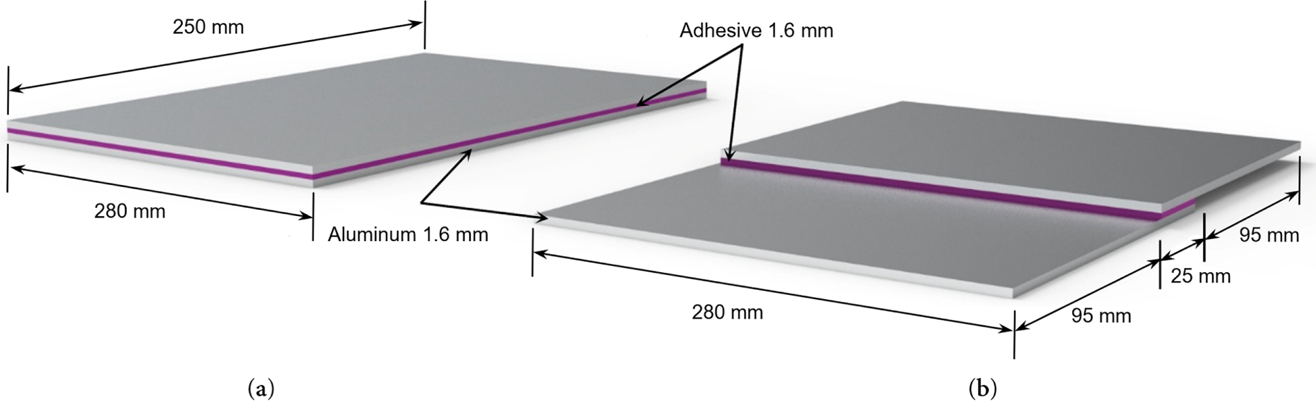
Figure 1: Object under investigation; a—bonded aluminum plates, b—lap joint. Dimensions are not in scale.
The first investigated structure consisted of two aluminum plates, each 1.6 mm thick, bonded together with a 0.16 mm layer of structural AF163 adhesive (Fig. 1a). Another investigated structure had a different configuration, consisting of a single lap joint with a 25 mm bonded zone (Fig. 1b). Aluminum material and thickness configuration was selected due to its widespread application in structural components in the aerospace industry. The structural adhesive properties were designed to represent a range of bond qualities from high-strength bonds to weak bonds to evaluate the sensitivity of the investigation to different bonding conditions.
2.2 Analysis of Guided Waves Dispersion Curves
The first step in the theoretical analysis of the propagation of ultrasonic guided waves in adhesively bonded aluminum plates is the calculation of dispersion curves. Dispersion curves were calculated at the cross-section of an infinitely wide multilayered plate using the one-dimensional (1D) semi-analytical finite element (SAFE) method [33]. Graphical representation of the SAFE model is shown in Fig. 2.
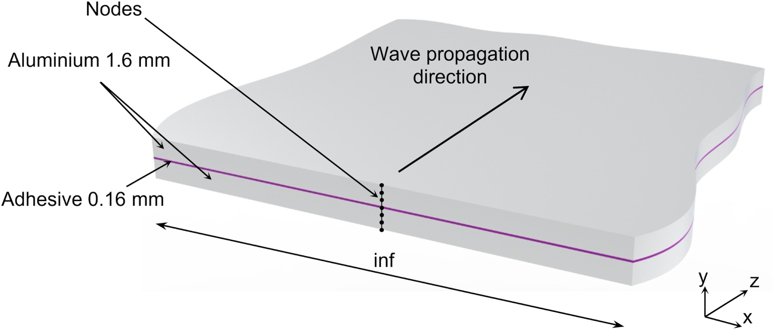
Figure 2: Graphical representation of the SAFE model.
Young’s modulus E, Poisson’s ratio ν and density ρ of aluminum and AF163 structural adhesive used in numerical modelling are presented in Table 1. Cured AF163 adhesive properties were measured using the ultrasonic pulse—echo technique [34], and they differed from manufacturer data [35]. Therefore, for numerical investigation, we included two additional cases with intermediate properties—hypothetical adhesive E2 and E3.
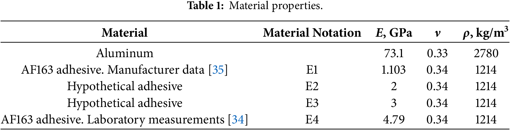
In the present study, variations in adhesive properties refer specifically to changes in the elastic modulus of the adhesive layer, while density and Poisson’s ratio were kept constant for all cases. In this study, the weak bond was modeled by reducing the elastic modulus of a continuous adhesive layer, without introducing any physical gap or defect at the interface. This approach represents a weakened bonding condition with preserved geometric continuity, commonly used to simulate weak bonds in numerical studies.
Calculated phase and group velocity curves for high stiffness (E4) and low stiffness adhesive (E1) cases are presented in Fig. 3. Comparison of the dispersion curves shows that the fundamental A0 Lamb wave mode is not sensitive to variations in adhesive material properties. In contrast, significant variations in the fundamental S0 Lamb wave mode are clearly visible in the 300–700 kHz frequency range. The sensitivity of the S0 Lamb wave mode to adhesive stiffness is mainly related to its symmetric deformation pattern, which induces significant in-plane stresses across the adhesive layer. As a result, variations in adhesive stiffness directly affect the effective stiffness of the multilayer plate, leading to observable changes in the S0 mode velocity. In contrast, the A0 mode is dominated by flexural motion, which involves lower in-plane stress transfer through the adhesive layer, making it considerably less sensitive to changes in adhesive stiffness. From an energy perspective, increasing adhesive stiffness enhances the mechanical coupling between the bonded plates, leading to stronger confinement of elastic energy within the bonded region and, consequently, to a reduction of the S0 mode group velocity in the investigated frequency range. Therefore, we can assume that this sensitivity feature of the S0 mode can be used to detect variations in adhesive properties within the bonded structure. Variations in higher-order guided wave modes are also noticeable. However, the excitation of such modes using conventional ultrasonic transducers is complicated.
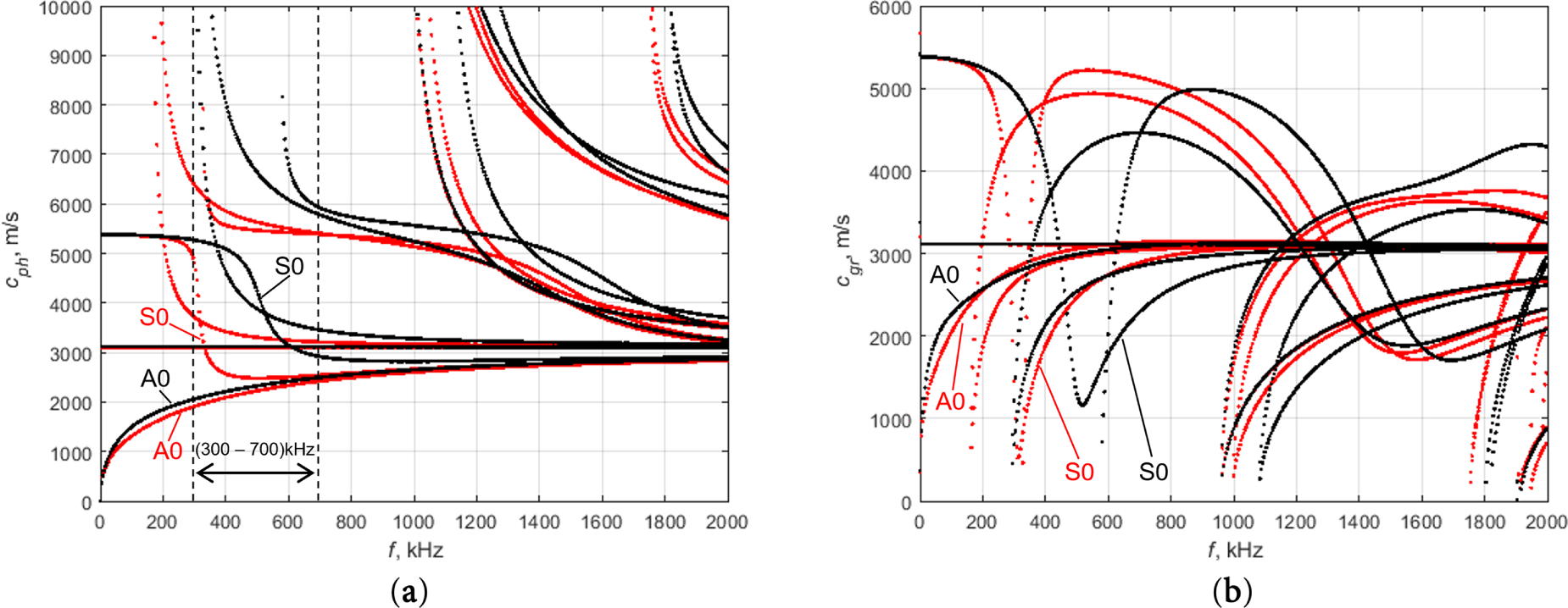
Figure 3: Phase velocity (a) and group velocity (b) dispersion curves of guided waves propagating in an adhesively bonded aluminum structure; Black color—adhesive E4, red color—E1.
2.3 Numerical Modelling of Guided Wave Propagation in Adhesively Bonded Structures
Numerical modelling of ultrasonic guided wave propagation was performed in an adhesively bonded aluminum structure and in an adhesively bonded lap joint using the OnScale finite element software. Graphical representation of both models is provided in Fig. 4.
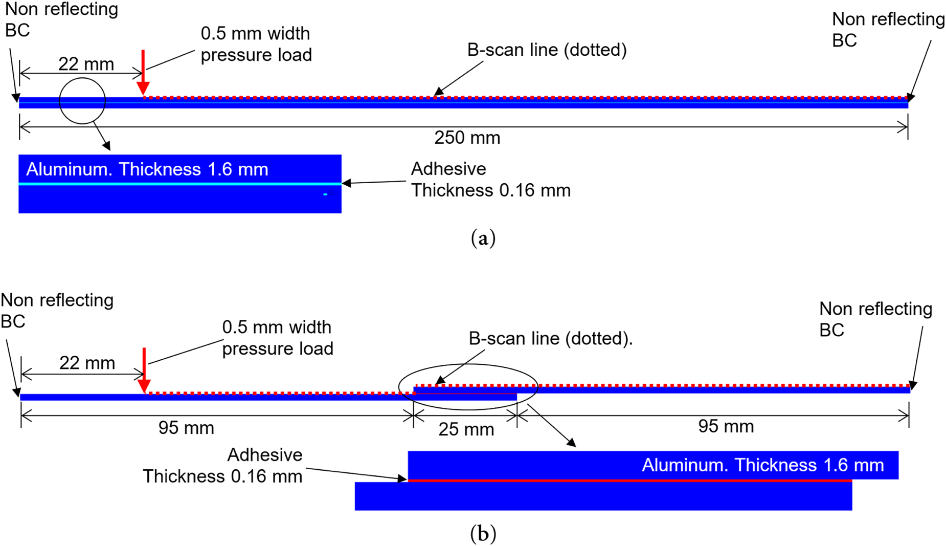
Figure 4: Graphical representation of finite element models; (a) adhesively bonded structure, (b) adhesively bonded lap joint.
The first investigation was carried out on the adhesively bonded structure, which consisted of two 1.6 mm thick aluminum plates bonded with 0.16 mm thick adhesive layer (Fig. 4a). Next investigation was carried out on more complex configuration—single lap-joint of adhesively bonded materials (Fig. 4b). The thickness of the aluminum and adhesive layer was the same as in the previous model, as well as properties of the adhesives were used the same as in previous case. In this configuration, only 25 mm of the structure was bonded adhesively.
In both cases, the excitation of ultrasonic guided waves was performed by simulation of 0.5 mm wide point-type pressure load. The excitation signal was a wideband 500 kHz Ricker wavelet. The time diagram and frequency spectrum of the excitation signal is presented in Fig. 5. The nominal mesh size of 0.22 mm was selected based on the shortest wavelength at 500 kHz frequency, corresponding to approximately 20 finite elements per wavelength. The adhesive layer and material interfaces were explicitly defined using key points, allowing the solver to automatically apply local mesh refinement in the adhesive layer. Although the adhesive thickness is smaller than the nominal element size, this structured meshing strategy ensures accurate discretization. Non-reflecting boundary conditions were applied to both left and right edges of the model to minimize reflections. The finite element package employs an explicit dynamic time integration method. As this method is conditionally stable, the maximum allowable time step is automatically determined by the software based on the mesh size and material properties. In the present modeling study, the time step was set to 0.8 of the maximum stable value to ensure numerical stability and accuracy. This choice was verified to provide sufficient temporal resolution for the highest frequency components of the excitation signal. Out-of-plane particle velocity components of the propagating guided waves were recorded at each node along the B-scan line. As a result, all data required for further analysis were obtained.
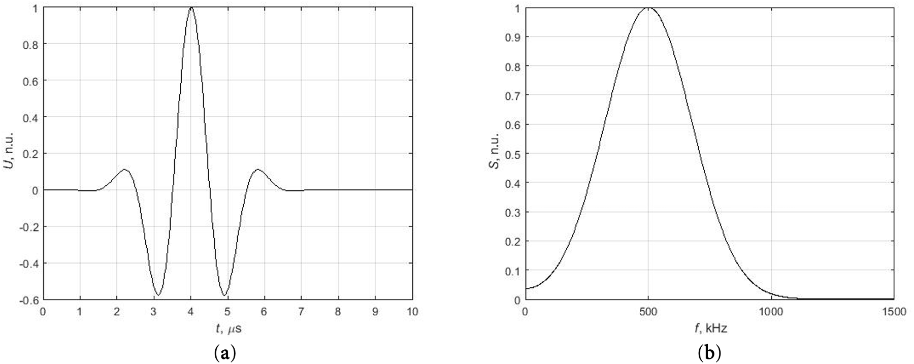
Figure 5: Excitation pulse, (a) time diagram, (b) spectrum.
2.4 Calculation of Phase and Group Velocity Characteristics
Analysis of propagating guided waves can be performed from the point of view of the phase and group velocity of guided waves. Phase velocity dispersion characteristics of the guided waves from the finite element modeling results can be obtained using the two-dimensional Fourier transform (2D FFT) [36]. According to 2D FFT method, the wave propagating along the object under investigation can be expressed by the function of coordinate and time u(x,t) and can be transformed into the wavenumber k and frequency space using the two-dimensional Fourier transform:
where x is the coordinate, t is the time, ω = 2πf is the angular frequency, k is the wavenumber.
Phase velocity is expressed as:
Another way to determine the changes of adhesive properties in the structure under investigation is the analysis of group velocity. Calculation of group velocity characteristics can be performed using the Short Time Fourier transform and requires a single signal at the selected position.
The short-time Fourier transform (STFT) is one of the most widely used time-frequency representations of various signals. The STFT is the Fourier transform applied to a short segment of the signal. Analysed signal is divided into short overlapping segments, and a window function is applied to each segment. Further, the Fourier transform is calculated [37]. The STFT of the signal y(t) is expressed as:
where h(τ) is window function.
When arrival time of the wave ta and propagation distance L are known, the group velocity of the waves can be calculated as:
3.1 Analysis of the Phase Velocity of the Guided Waves Propagating in an Adhesively Bonded Structure
The results of the numerical modelling of dynamic wave propagation in adhesively bonded structures, including B-scan and 2D Fourier transform (2D FFT) images for high and low stiffness adhesives, are presented in Figs. 6 and 7, respectively.
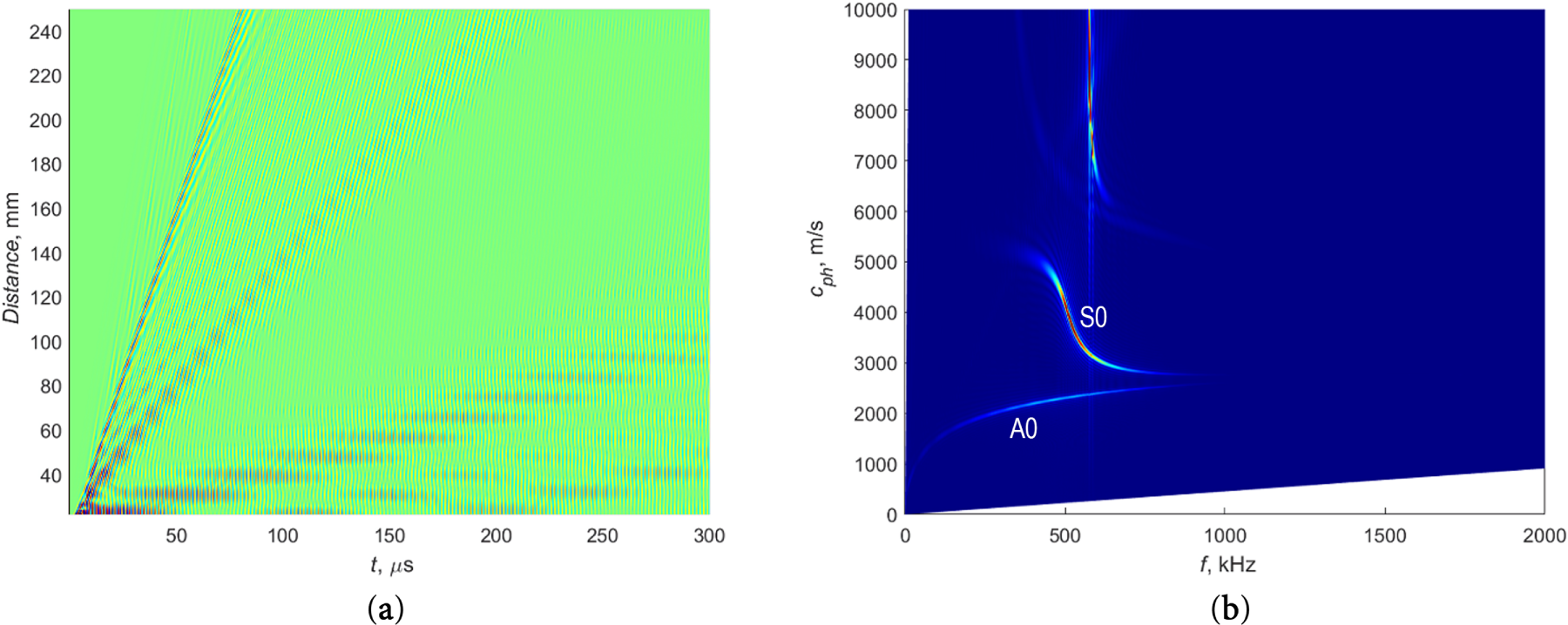
Figure 6: B-scan (a) and 2D FFT (b) images of guided waves propagating in an adhesively bonded structure with high-stiffness adhesive E4.
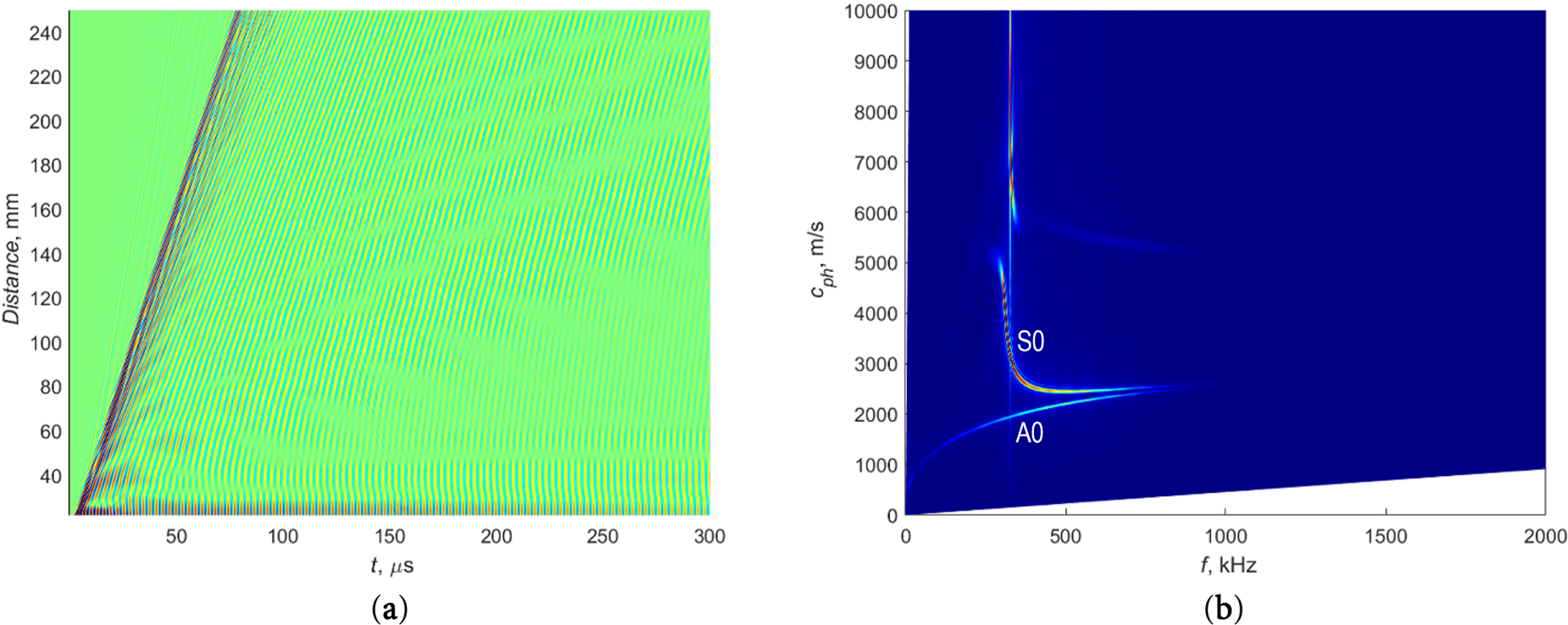
Figure 7: B-scan (a) and 2D FFT (b) images of guided waves propagating in an adhesively bonded structure with low stiffness adhesive E1.
B-scan images represent the out-of-plane component of the propagating ultrasonic guided wave. The 2D FFT images illustrate the phase velocity dependence of guided waves on frequency. It is clearly seen that adhesive properties have strong influence on S0 Lamb wave propagation characteristics, as well as that the A0 mode is not sensitive to adhesive properties variation. Analysis of phase velocity data allows to determine changes in adhesive properties within the bonded structure. However, the calculation of 2D FFT requires scanning to get all B-scan data, and this may not always be convenient for the investigation of real objects. In such a case, a group velocity analysis can be applied.
3.2 Analysis of Group Velocity of Ultrasonic Guided Waves in a Simple Model of an Adhesively Bonded Structure
The STFT was applied to the above mentioned two models in order to calculate group velocities. One model is a simple adhesively bonded structure, which is shown in Fig. 4a. Another model with a more complex configuration form is a single lap-joint of adhesively bonded materials shown in Fig. 4b.
Signals for analysis were recorded at a distance of 178 mm from the excitation zone. Time-domain diagrams of these signals from structures with different adhesive properties were obtained. The STFTs of these signals were calculated using a standard MATLAB function, with a Hann window with a length of 18 μs and an overlap of 90%, providing a suitable balance between time and frequency resolution. Then, group velocity characteristics were calculated from STFTs.
Firstly, in this study, a simple configuration of an adhesively bonded structure was investigated. Time-domain diagrams from structures with different adhesive properties are presented in Fig. 8a,c,e,g. Group velocity characteristics obtained using the STFT technique are presented in Fig. 8b,d,f,h. Fig. 8a–h correspond to adhesive stiffness of 4.79, 3, 2 and 1.103 GPa, respectively. The numerical model was verified by comparing the group velocity values obtained from finite element simulations and STFT analysis with those calculated using the semi-analytical finite element method. As shown in Fig. 8b, a good agreement between the two approaches is observed for the high-stiffness adhesive case, confirming the correctness of the numerical model and signal processing procedure.
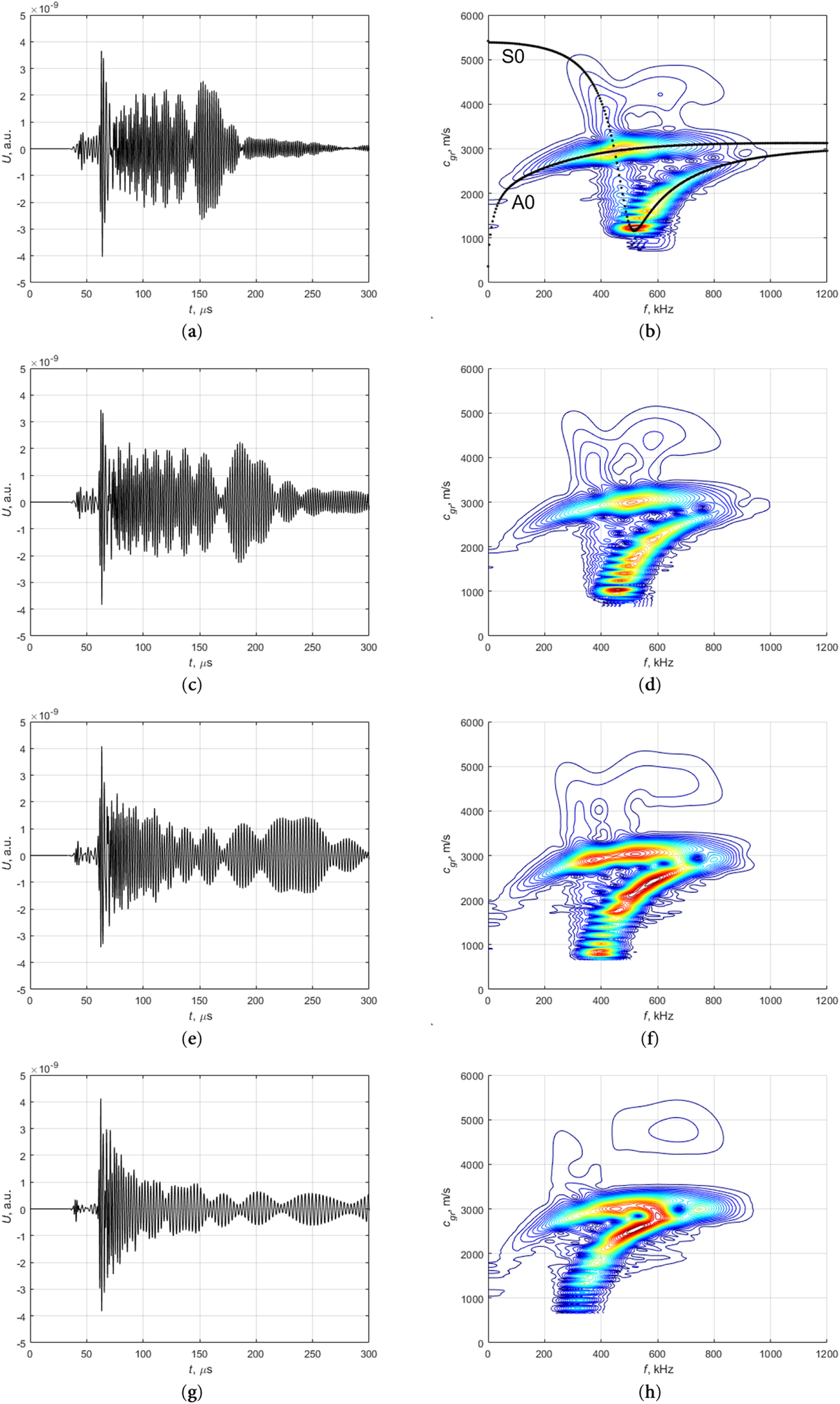
Figure 8: Signals in the time domain recorded at 178 mm distance from the excitation zone and calculated group velocities using the STFT technique for an adhesively bonded structure with different adhesive stiffness: (a,b) E4, (c,d) E3, (e,f) E2, (g,h) E1.
In order to identify features that could detect variations in the adhesive properties, a cross-section of the group velocity data was taken at a frequency of 500 kHz, as shown in Fig. 9a. Peaks observed at a group velocity of approximately 3000 m/s correspond to the A0 Lamb wave mode, while the peaks at lower group velocity correspond to the S0 mode.
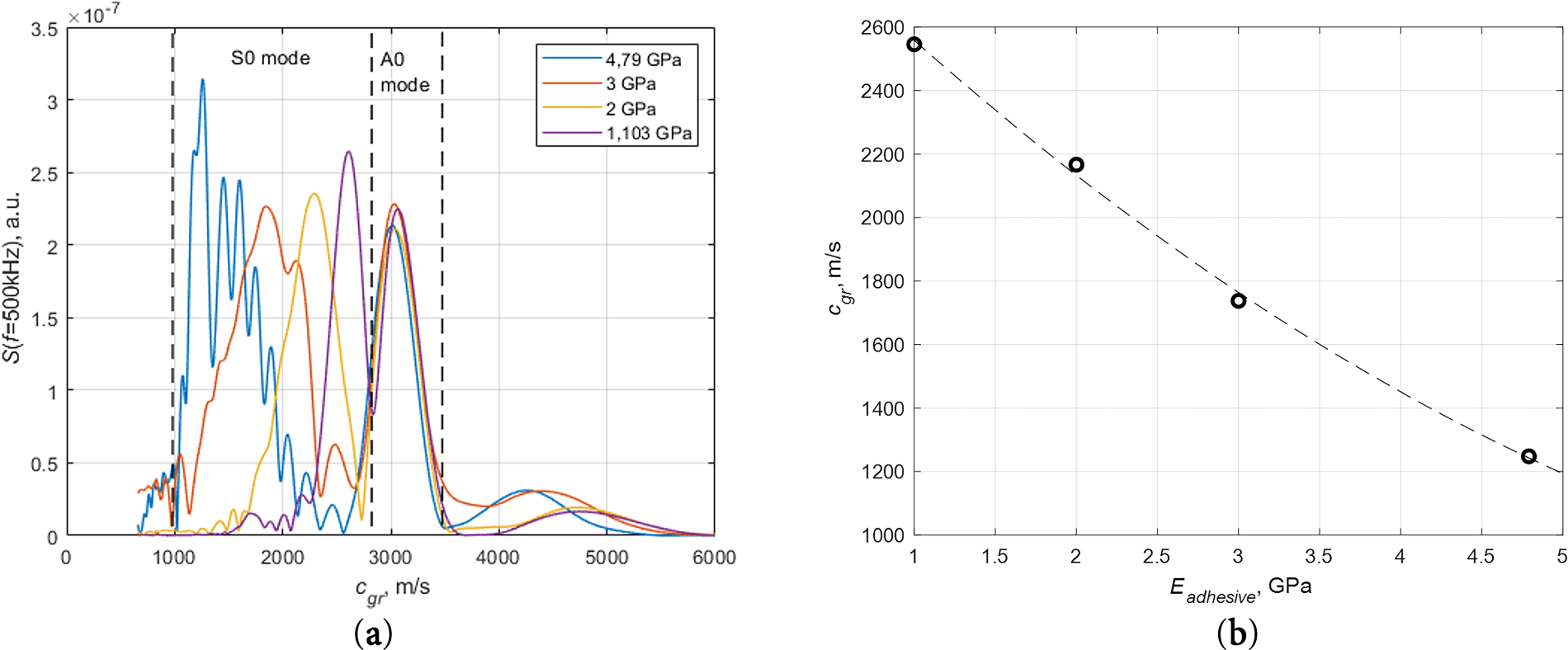
Figure 9: Cross-section of the group velocity data at 500 kHz (a) and S0 mode group velocity dependence on stiffness of adhesive (b) in the case of an adhesively bonded structure.
The results demonstrate that the group velocity of the A0 mode does not depend on the adhesive properties, making them unsuitable for the characterization of the adhesive bond. On the contrary, the S0 mode demonstrates a strong dependence on adhesive stiffness, which can be a reliable indicator for investigating the condition of adhesive properties in bonded structures. The dependence of S0 mode velocity on adhesive stiffness is presented in Fig. 9b. Obtained results are interpolated using a second-degree polynomial, providing a practical means of interpreting adhesive stiffness from measured velocities.
3.3 Ultrasonic Guided Waves in the Lap-Joint Model of an Adhesively Bonded Structure
A more complex configuration was investigated as well in the form of an adhesively bonded lap joint, shown in Fig. 4b. Obtained time-domain diagrams from structures with different adhesive properties, and their corresponding STFTs are presented in Fig. 10. Fig. 10a–h correspond to adhesive stiffness of 4.79, 3, 2, and 1.103 GPa, respectively. It could be observed that due to the more complex structure of the object of investigation dependence of group velocity on the frequency is also more complex than in the simple adhesively bonded structure (Fig. 8).
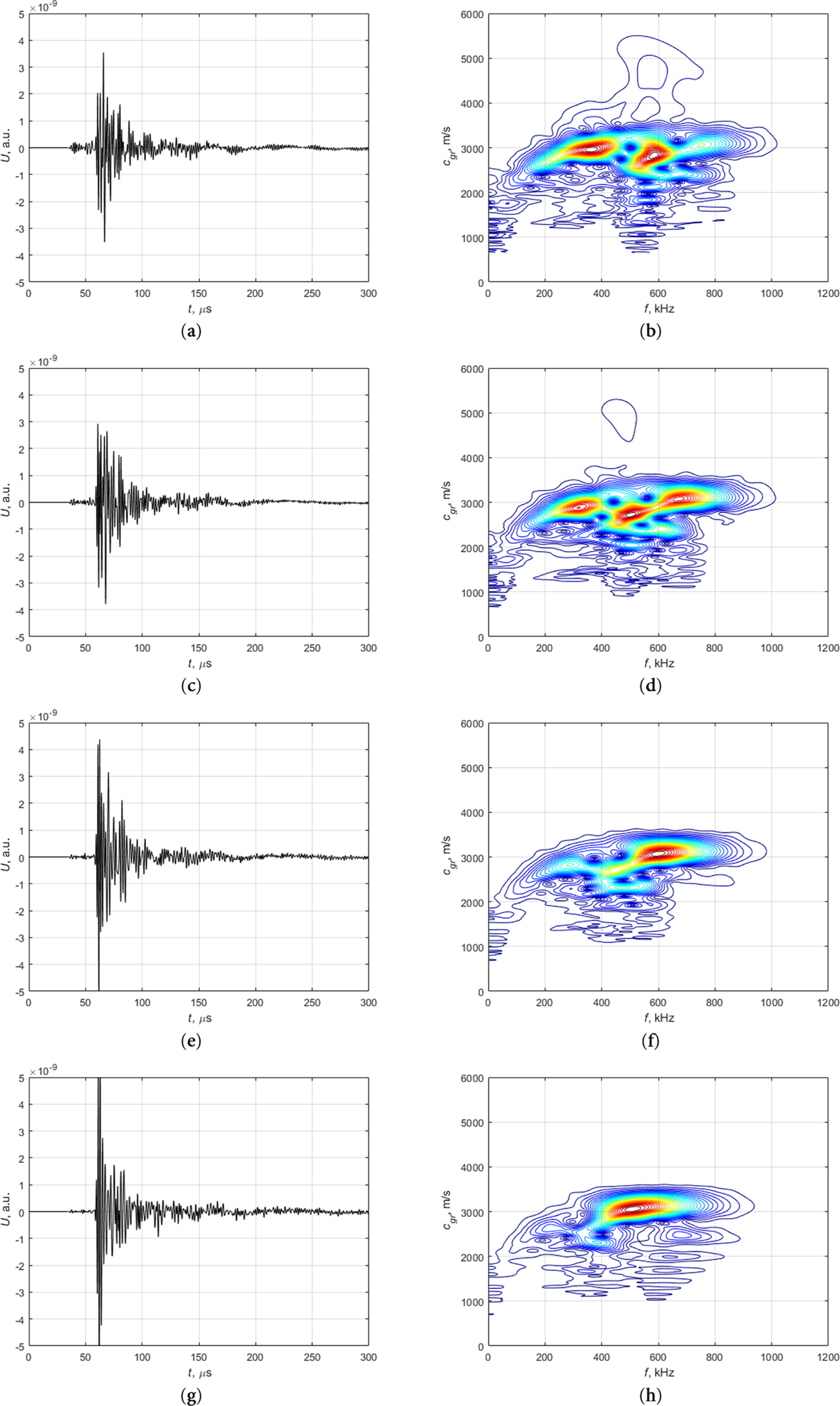
Figure 10: Signals in time domain recorded at 178 mm distance from excitation zone and calculated group velocities using STFT technique for lap joint bonded structure with adhesive stiffness: (a,b) E4, (c,d) E3, (e,f) E2, (g,h) E1.
Cross sections of the group velocity characteristics at 500 kHz are shown in Fig. 11a. In comparison to the simple bonded structure, the A0 and S0 modes cannot be distinctly separated in the lap joint configuration due to multiple reflections, transmissions, and mode conversions occurring at the boundaries of the bonded region. The excited Lamb wave propagates sequentially through the lower aluminum plate, the adhesively bonded overlap region, and the upper aluminum plate. Since the wave propagation velocity in the aluminum plates remains constant for all investigated cases, variations in the total wave arrival time are solely caused by changes in the propagation velocity within the adhesively bonded region. Therefore, an average group velocity, calculated from the total propagation distance and the measured arrival time (Eq. (4)), can be used as an effective parameter to characterize the influence of adhesive stiffness in the lap joint.
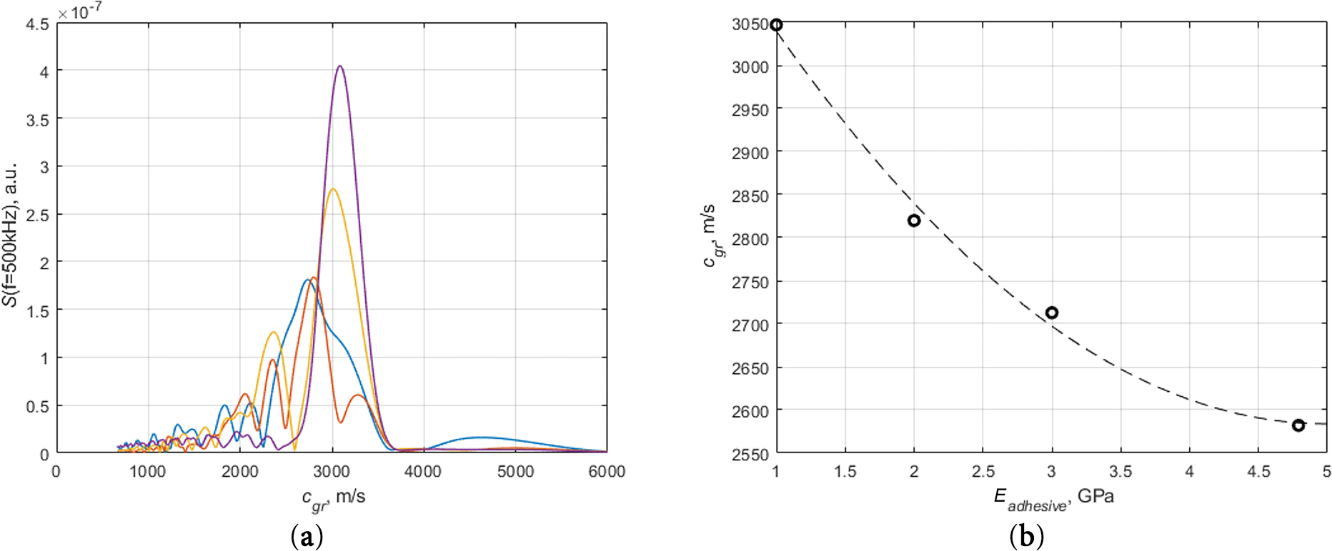
Figure 11: Cross-section of the group velocity data at 500 kHz (a) and S0 mode group velocity dependence on stiffness of adhesive (b) in the case of a lap joint structure.
The dependence of STFT peak positions on adhesive properties is shown in Fig. 11b. The obtained results demonstrate that the analysis of group velocity of the wave can be reliably utilized for characterizing adhesive properties even in lap joint configurations of the adhesively bonded lap joint case. Despite the increased complexity of the configuration, the method provides robustness in detecting variations in adhesive stiffness and assessing the quality of adhesive bonds.
3.4 Discussion and Limitations
For the simple bonded plate configuration, the S0 Lamb wave mode can be clearly identified, and its group velocity exhibits a direct dependence on adhesive stiffness. In contrast, the lap joint configuration introduces strong mode overlap, reflections, and mode conversions due to geometric discontinuities. This makes it difficult to separate individual modes reliably. Despite the increased complexity, the effective average group velocity extracted from the received signal remains clearly sensitive to adhesive stiffness. This comparison demonstrates that although simple bonded structures allow more straightforward physical interpretation, the proposed approach remains applicable to realistic lap joint geometries using a robust and experimentally feasible velocity-based feature.
It should be emphasized that the empirical relationship obtained between group velocity and adhesive stiffness is specific to the material system, geometry, and frequency range examined in this study, and should not be directly generalized to other configurations without additional verification. However, we expect this relationship to be similar for other lap joint configurations as well. The present study is subject to several further limitations. The adhesive layer thickness was assumed to be constant, and variations in thickness were not considered. Environmental effects such as temperature variations, material attenuation, and viscoelastic behavior of the adhesive were not included and may influence guided wave propagation and group velocity measurements in practical applications. Furthermore, the investigation was limited to flat plate and lap joint configurations. For structures with a large radius of curvature, Lamb wave propagation can often be approximated using flat-plate models. However, the applicability of the proposed approach to curved panels with smaller radii or to more complex multilayered structures would require additional investigation.
Higher-order guided wave modes may exhibit increased sensitivity to bonding properties in multilayer structures [38,39]. However, the practical excitation and extraction of higher-order modes often require advanced transducer configurations, such as phased array systems. In contrast, the present study intentionally focuses on the fundamental A0 and S0 modes, which can be reliably generated using conventional ultrasonic transducers and simple excitation techniques. This choice allows the proposed approach to remain robust, experimentally feasible, and readily transferable to practical non-destructive evaluation scenarios. Nevertheless, the extension of the proposed methodology to include higher-order modes represents an interesting direction for future research, particularly for complex multilayered structures.
A numerical study of ultrasonic guided wave propagation in adhesively bonded samples is presented in this paper. The modelling of the guided wave propagation in the investigated structures was performed using the finite element method. Calculated dispersion curves showed that there are significant variations in the velocity of the S0 Lamb wave mode in the 300–700 kHz frequency range on the mechanical properties of the adhesive. This feature has been exploited for the application in the investigation of the quality of adhesion in adhesively bonded aluminum plates. Group velocity analysis was chosen because single signal analysis at selected positions can be performed without scanning. Processing of the obtained signals was performed by the time–frequency technique using the short-time Fourier transform, and group velocities of ultrasonic guided waves were calculated. The results obtained show that the group velocity of the A0 mode is independent of the adhesive properties. However, the S0 mode shows a strong dependence. The group velocity of the S0 mode decreases as the stiffness of the adhesive increases. The case of adhesively bonded lap joints is more complex. Results obtained by STFT do not show a clear separation of A0 and S0 modes. However, the analysis of the average group velocity of the waves shows the dependence of the group velocity on the adhesive properties. As in the previous case, the average group velocity in lap joints serves as an effective parameter that captures the influence of adhesive stiffness despite strong modal overlap and complex wave interactions.
Future work will focus on experimental validation of the proposed approach and on extending the analysis to more complex bonding configurations and defect types. Furthermore, the integration of automated signal processing methods, such as machine learning techniques, could further enhance the practical applicability of the method.
Acknowledgement: Not applicable.
Funding Statement: This research was supported by the Research Council of Lithuania (LMTLT), agreement no. S-MIP-22-5.
Author Contributions: The authors confirm contribution to the paper as follows: Conceptualization, Egidijus Žukauskas and Elena Jasiūnienė; methodology, Egidijus Žukauskas and Elena Jasiūnienė; software, Egidijus Žukauskas; validation, Egidijus Žukauskas; resources, Egidijus Žukauskas and Elena Jasiūnienė and Damira Smagulova; data curation, Egidijus Žukauskas and Elena Jasiūnienė; writing—original draft preparation, Egidijus Žukauskas and Damira Smagulova; writing—review and editing, Egidijus Žukauskas and Elena Jasiūnienė and Damira Smagulova; visualization, Egidijus Žukauskas; supervision, Elena Jasiūnienė; project administration, Elena Jasiūnienė; funding acquisition, Elena Jasiūnienė. All authors reviewed and approved the final version of the manuscript.
Availability of Data and Materials: Data will be made available on request.
Ethics Approval: Not applicable.
Conflicts of Interest: The authors declare no conflicts of interest.
References
1. Samaitis V, Yilmaz B, Jasiuniene E. Adhesive bond quality classification using machine learning algorithms based on ultrasonic pulse-echo immersion data. J Sound Vib. 2023;546:117457. doi:10.1016/j.jsv.2022.117457. [Google Scholar] [CrossRef]
2. Kumar Akkasali N, Biswas S, Kumar Panda S. Deflection and stress characteristics of single lap joint (adhesively bonded) theoretical analysis and experimental verification. Compos Struct. 2024;344:118375. doi:10.1016/j.compstruct.2024.118375. [Google Scholar] [CrossRef]
3. Attar L, Ech Cherif El Kettani M, Leduc D, Predoi MV, Galy J. Detection of kissing bond type defects and evaluation of the bonding quality in metal/adhesive/composite structures by a wavenumber-frequency insensitive SH mode. NDT E Int. 2023;137(1):102841. doi:10.1016/j.ndteint.2023.102841. [Google Scholar] [CrossRef]
4. Jairaja R, Narayana Naik G. Numerical studies on weak bond effects in single and dual adhesive bonded single lap joint between CFRP and aluminium. Mater Today Proc. 2020;21:1064–8. doi:10.1016/j.matpr.2020.01.006. [Google Scholar] [CrossRef]
5. Abbasi M, Ciardiello R, Goglio L. A novel approach for damage assessment in adhesively bonded composite joints using backface strain technique. Compos Part B Eng. 2024;286:111766. doi:10.1016/j.compositesb.2024.111766. [Google Scholar] [CrossRef]
6. Ehrhart B, Valeske B, Bockenheimer C. Non-destructive evaluation (NDE) of aerospace composites: Methods for testing adhesively bonded composites. In: Non-destructive evaluation (NDE) of polymer matrix composites. Amsterdam, The Netherland: Elsevier; 2013. p. 220–37. doi:10.1533/9780857093554.2.220. [Google Scholar] [CrossRef]
7. Spytek J, Ambrozinski L, Pieczonka L. Evaluation of disbonds in adhesively bonded multilayer plates through local wavenumber estimation. J Sound Vib. 2022;520:116624. doi:10.1016/j.jsv.2021.116624. [Google Scholar] [CrossRef]
8. Yılmaz B, Jasiūnienė E. Advanced ultrasonic NDT for weak bond detection in composite-adhesive bonded structures. Int J Adhes Adhes. 2020;102:102675. doi:10.1016/j.ijadhadh.2020.102675. [Google Scholar] [CrossRef]
9. Titov SA, Maev RG, Bogachenkov AN. Pulse-echo NDT of adhesively bonded joints in automotive assemblies. Ultrasonics. 2008;48(6–7):537–46. doi:10.1016/j.ultras.2008.07.001. [Google Scholar] [PubMed] [CrossRef]
10. Jasiūnienė E, Mažeika L, Samaitis V, Cicėnas V, Mattsson D. Ultrasonic non-destructive testing of complex titanium/carbon fibre composite joints. Ultrasonics. 2019;95:13–21. doi:10.1016/j.ultras.2019.02.009. [Google Scholar] [PubMed] [CrossRef]
11. Palumbo D, Tamborrino R, Galietti U, Aversa P, Tatì A, Luprano VAM. Ultrasonic analysis and lock-in thermography for debonding evaluation of composite adhesive joints. NDT E Int. 2016;78(4):1–9. doi:10.1016/j.ndteint.2015.09.001. [Google Scholar] [CrossRef]
12. Crane RL, Hart-Smith J, Newman J. Nondestructive inspection of adhesive bonded joints. In: Adhesive bonding. Amsterdam, The Netherland: Elsevier; 2021. p. 215–56. doi:10.1016/b978-0-12-819954-1.00008-3. [Google Scholar] [CrossRef]
13. Yilmaz B, Asokkumar A, Jasiūnienė E, Kažys RJ. Air-coupled, contact, and immersion ultrasonic non-destructive testing: comparison for bonding quality evaluation. Appl Sci. 2020;10(19):6757. doi:10.3390/app10196757. [Google Scholar] [CrossRef]
14. Zabbal P, Ribay G, Jumel J. Evaluation of metallic bonded plates with nonlinear ultrasound and comparison with destructive testing. NDT E Int. 2021;123(34–51):102514. doi:10.1016/j.ndteint.2021.102514. [Google Scholar] [CrossRef]
15. Zhang K, Li S, Zhou Z. Detection of disbonds in multi-layer bonded structures using the laser ultrasonic pulse-echo mode. Ultrasonics. 2019;94(82):411–8. doi:10.1016/j.ultras.2018.06.005. [Google Scholar] [PubMed] [CrossRef]
16. Zhou H, Gao F, Gu P. Research on laser ultrasonic propagation characteristics and quantitative detection of delamination of carbon fiber composite. Optik. 2022;271(111201):170173. doi:10.1016/j.ijleo.2022.170173. [Google Scholar] [CrossRef]
17. Santos M, Santos J. Adhesive single-lap joint evaluation using ultrasound guided waves. Appl Sci. 2023;13(11):6523. doi:10.3390/app13116523. [Google Scholar] [CrossRef]
18. Ramadas C, Padiyar J, Balasubramaniam K, Joshi M, Krishnamurthy CV. Lamb wave based ultrasonic imaging of interface delamination in a composite T-joint. NDT E Int. 2011;44(6):523–30. doi:10.1016/j.ndteint.2011.05.009. [Google Scholar] [CrossRef]
19. Spytek J, Ziaja-Sujdak A, Dziedziech K, Pieczonka L, Pelivanov I, Ambrozinski L. Evaluation of disbonds at various interfaces of adhesively bonded aluminum plates using all-optical excitation and detection of zero-group velocity Lamb waves. NDT E Int. 2020;112(2):102249. doi:10.1016/j.ndteint.2020.102249. [Google Scholar] [CrossRef]
20. Mustapha S, Ye L. Non-destructive evaluation (NDE) of composites: assessing debonding in sandwich panels using guided waves. In: Non-destructive evaluation (NDE) of polymer matrix composites. Amsterdam, The Netherland: Elsevier; 2013. p. 238–78. doi:10.1533/9780857093554.2.238. [Google Scholar] [CrossRef]
21. Zou X, Wang L, Wang J, Liu J, Ma H, Bao Y. Nondestructive evaluation of carbon fiber reinforced polymer (CFRP)-steel interfacial debonding using eddy current thermography. Compos Struct. 2022;284(8):115133. doi:10.1016/j.compstruct.2021.115133. [Google Scholar] [CrossRef]
22. Barus M, Welemane H, Nassiet V, Pastor ML, Cantarel A, Collombet F, et al. NDT-based design of joint material for the detection of bonding defects by infrared thermography. NDT E Int. 2018;93:157–63. doi:10.1016/j.ndteint.2017.10.005. [Google Scholar] [CrossRef]
23. Zhang Y, Xu C, Liu P, Xie J, Liu R, Zhao Q. Enhanced recognition of bonding interface defects within CFRP-steel adhesive structures via thermal signals in low-power vibrothermography. Constr Build Mater. 2024;456(8):139329. doi:10.1016/j.conbuildmat.2024.139329. [Google Scholar] [CrossRef]
24. Solodov I, Kornely M, Philipp J, Stammen E, Dilger K, Kreutzbruck M. Linear vs. nonlinear ultrasonic testing of kissing bonds in adhesive joints. Ultrasonics. 2023;132(1–8):106967. doi:10.1016/j.ultras.2023.106967. [Google Scholar] [PubMed] [CrossRef]
25. Jeenjitkaew C, Guild FJ. The analysis of kissing bonds in adhesive joints. Int J Adhes Adhes. 2017;75:101–7. doi:10.1016/j.ijadhadh.2017.02.019. [Google Scholar] [CrossRef]
26. Droździel M, Podolak P, Nardi D, Jakubczak P. The mechanical effects of kissing bonding defects in hybrid metal-composite laminates. Compos Struct. 2021;269(7):114027. doi:10.1016/j.compstruct.2021.114027. [Google Scholar] [CrossRef]
27. Wei Y, Jin X, Luo Q, Li Q, Sun G. Adhesively bonded joints-a review on design, manufacturing, experiments, modeling and challenges. Compos Part B Eng. 2024;276(5):111225. doi:10.1016/j.compositesb.2024.111225. [Google Scholar] [CrossRef]
28. Ghose B, Panda RS, Balasubramaniam K. Guided A0 wave mode interaction with interfacial disbonds in an elastic-viscoelastic bilayer structure. NDT E Int. 2021;124:102543. doi:10.1016/j.ndteint.2021.102543. [Google Scholar] [CrossRef]
29. Rucka M, Wojtczak E, Lachowicz J. Damage imaging in lamb wave-based inspection of adhesive joints. Appl Sci. 2018;8(4):522. doi:10.3390/app8040522. [Google Scholar] [CrossRef]
30. Gauthier C, Ech-Cherif El-Kettani M, Galy J, Predoi M, Leduc D, Izbicki JL. Lamb waves characterization of adhesion levels in aluminum/epoxy bi-layers with different cohesive and adhesive properties. Int J Adhes Adhes. 2017;74(2):15–20. doi:10.1016/j.ijadhadh.2016.12.002. [Google Scholar] [CrossRef]
31. Boll B, Willmann E, Fiedler B, Meißner RH. Weak adhesion detection-Enhancing the analysis of vibroacoustic modulation by machine learning. Compos Struct. 2021;273:114233. doi:10.1016/j.compstruct.2021.114233. [Google Scholar] [CrossRef]
32. Steinbild PJ, Höhne R, Füßel R, Modler N. A sensor detecting kissing bonds in adhesively bonded joints using electric time domain reflectometry. NDT E Int. 2019;102(3/4):114–9. doi:10.1016/j.ndteint.2018.11.013. [Google Scholar] [CrossRef]
33. Bartoli I, Marzani A, Lanza di Scalea F, Viola E. Modeling wave propagation in damped waveguides of arbitrary cross-section. J Sound Vib. 2006;295(3–5):685–707. doi:10.1016/j.jsv.2006.01.021. [Google Scholar] [CrossRef]
34. Yilmaz B, Smagulova D, Jasiuniene E. Model-assisted reliability assessment for adhesive bonding quality evaluation with ultrasonic NDT. NDT E Int. 2022;126:102596. doi:10.1016/j.ndteint.2021.102596. [Google Scholar] [CrossRef]
35. 3M. 3M Scotch-Weld Structural Adhesive Film AF 163-2: Technical datasheet [Internet]. 3M; 2024 [cited 2026 Jan 1]. Available from: https://multimedia.3m.com/mws/media/282041O/3m-scotch-weld-structural-adhesive-film-af-163-2-af-163-3.pdf. [Google Scholar]
36. Alleyne D, Cawley P. A two-dimensional Fourier transform method for the measurement of propagating multimode signals. J Acoust Soc Am. 1991;89(3):1159–68. doi:10.1121/1.400530. [Google Scholar] [CrossRef]
37. Niethammer M, Jacobs LJ, Qu J, Jarzynski J. Time-frequency representations of lamb waves. J Acoust Soc Am. 2001;109(5):1841–7. doi:10.1121/1.1357813. [Google Scholar] [PubMed] [CrossRef]
38. Yu X, Zuo P, Xiao J, Fan Z. Detection of damage in welded joints using high order feature guided ultrasonic waves. Mech Syst Signal Process. 2019;126(3):176–92. doi:10.1016/j.ymssp.2019.02.026. [Google Scholar] [CrossRef]
39. Xu J, Hu H, Liu QH, Han B. Ultrasonic modeling for multi-layered fluid-solid coupling structures considering defective interfaces: an efficient semi-analytical spectral element method. J Sound Vib. 2025;599(2):118861. doi:10.1016/j.jsv.2024.118861. [Google Scholar] [CrossRef]
Cite This Article
 Copyright © 2026 The Author(s). Published by Tech Science Press.
This work is licensed under a Creative Commons Attribution 4.0 International License , which permits unrestricted use, distribution, and reproduction in any medium, provided the original work is properly cited.
 Downloads
 Citation Tools