
 Submit a Paper
 Propose a Special lssue
 Open Access
ARTICLE

A 37 GHz Millimeter-Wave Antenna Array for 5G Communication Terminals
1 Telecommunication Engineering Department, University of Engineering and Technology, Mardan, 23200, Pakistan
2 Department of Electronics and Telecommunications, Politecnico di Torino, Turin, 10129, Italy
3 Istituto di Elettronica e di Ingegneria Dell’Informazione e Delle Telecomunicazioni, National Research Council of Italy, Turin, 10129, Italy
4 Department of Measurements and Optical Electronics, Politehnica University Timisoara, Timisoara, 300006, Romania
5 Research Institute for Microwave and Millimeter-Wave Studies (RIMMS), National University of Sciences and Technology (NUST), Islamabad, 44000, Pakistan
6 Department of Electronics and Computer Engineering Technology (JTKEK), Faculty of Electrical and Electronic Engineering Technology (FTKEE), Universiti Teknikal Malaysia Melaka (UTeM), Hang Tuah Jaya, Durian Tunggal, Melaka, 76100, Malaysia
* Corresponding Author: Sadiq Ullah. Email:
Computers, Materials & Continua 2023, 75(1), 1317-1330. https://doi.org/10.32604/cmc.2023.029879
Received 14 March 2022; Accepted 15 June 2022; Issue published 06 February 2023
 View Full Text
 Download PDF
Abstract
This work presents, design and specific absorption rate (SAR) analysis of a 37 GHz antenna, for 5th Generation (5G) applications. The proposed antenna comprises of 4-elements of rectangular patch and an even distribution. The radiating element is composed of copper material supported by Rogers RT5880 substrate of thickness, 0.254 mm, dielectric constant (εr), 2.2, and loss tangent, 0.0009. The 4-elements array antenna is compact in size with a dimension of 8 mm × 20 mm in length and width. The radiating patch is excited with a 50 ohms connector i.e., K-type. The antenna resonates in the frequency band of 37 GHz, that covers the 5G applications. The antenna behavior is studied both in free space and in the proximity of the human body. Three models of the human body, i.e., belly, hand, and head (contain skin, fat, muscles, and bone) are considered for on-body simulations. At resonant frequency, the antenna gives a boresight gain of 11.6 dB. The antenna radiates efficiently with a radiated efficiency of more than 90%. Also, it is observed that the antenna detunes to the lowest in the proximity of the human body, but still a good impedance matching is achieved considering the −10 dB criteria. Moreover, SAR is also being presented. The safe limit of 2 W/kg for any 10 g of biological tissue, specified by the European International Electro Technical Commission (IEC) has been considered. The calculated values of SAR for human body models, i.e., belly, hand and head are 1.82, 1.81 and 1.09 W/kg, respectively. The SAR values are less than the international recommendations for the three models. Furthermore, the simulated and measured results of the antenna are in close agreement, which makes it, a potential candidate for the fifth-generation smart phones and other handheld devices.Keywords
The rapid growth in the demand for enhanced low latency, data rates, and better capacity in the wireless communication, have focused the attention of many researchers toward the development of 5th Generation (5G) technology [1], where the role of a Millimeter-Wave (mm-wave) technology becomes important due to the large available bandwidth feature [2,3]. In this regard, the well-known 37–40 GHz mm-wave band is considered as a favorable candidate for 5G communication which can provide a platform for the higher data rates and bandwidth as well as low latency [4]. But the mm-wave technology is limited to short distance communication due to the suffering of these frequencies, greatly by the path loss while propagating [5,6]. To tackle the problem, there is a need of high gain antenna arrays at the mobile and base station terminals.
It is easy to adapt the antenna arrays of even large and complex geometries or feeding structure for the base stations with multiple antenna elements to get a high gain at least more than 10 dB for mobile communication [7,8]. However, for mobile stations, the employment of multiple antenna elements arrays is challenging as the partial volume must be reserved for candidate antennas, covering the sub 6 GHz spectrum. For mobile phones and similar devices these antennas shall be light weight, small size, low profile and simple to manufacture. Microstrip antenna technology offers these features and in addition they are more versatile in terms of frequency, pattern and polarization diversity and hence can be considered as a potential candidate for both the mobile phone and base station [9–13].
The advancement in research on mm-Wave technologies, mainly on wireless and mobile devices, has increased interest in understanding how the propagation of these waves influences the human body. Also, to investigate the possible health effects related to the higher frequency exposures. The interaction of mobile phone and similar devices with the lossy human body is of a great interest in wireless and mobile communication. Especially, hand and head, affect the antenna overall performance, particularly the peak gain, input impedance, radiation pattern, radiation efficiency and impedance matching [14]. In addition, the resonant frequency of the antenna detunes to the left or to the right of the resonant point. Moreover, if the antenna under test, is in near contact with the body, the side and back lobe radiations are absorbed in tissues resulting a serious health implication [15]. The amount of power absorbed per unit mass of the human body, when it is exposed to Electromagnetic (EM) radiation is known as specific absorption rate. SAR is the measure of the EM radiations absorbed by human body per unit mass and can be calculated in watt per kilogram (W/kg) [16]. Due to the health implication of the EM radiations for the mobile phones and handheld devices in mmWave spectrum, the international agencies such as the IEC or the Federal Communication Commission (FCC) set the maximum limit of the EM radiations absorbed by the human body without causing any health implication. The FCC specifies the SAR upper threshold to 1.6 W/kg averaged over 1 g of biological tissues, whereas the acceptable threshold of SAR set by the IEC is 2 W/kg, averaged over 10 g of biological tissues [17].
This paper presents a four element, planar microstrip array antenna operating at 37 GHz, which can be employed in 5G mobile phones and similar devices. The transmission line and quarter wavelength transformation techniques are used for the impedance and phase matching. Both the single element and 4-elements array antennas are analyzed using Computer Simulation Technology® Microwave Studio (CST MWS). The rest of the paper is structured as follows: Section 2, describes the antenna geometry and related theory. Results and findings are given in Section 3. The specific absorption rate is discussed in Section 4, while Section 5 concludes this work and gives recommendations for the future.
This section presents the final geometry and design evolution steps of the proposed design (Fig. 1). The antenna design is composed of 0.254 mm thicker Roger-5880 substrate of size (L × W = 6 × 10 mm2), having a dielectric constant (εr) of 2.2, and loss tangent of 0.0009. Thinner substrates offer lower surface wave losses, and as a result it is helpful to achieve good gain and efficiency. The substrate is backed by a finite ground plane of similar length and width as that of the substrate. The overall volume of the single element antenna is 10 × 6 × 0.254 mm3. A 50-Ohm connector is used as a source probe for the excitation of the antenna while a quarter wave transformation technique is used for matching the transmission line. Table 1 lists the proposed antenna [18] various dimensions. To calculate the dimensions of the proposed antenna, the rectangular patch antenna transmission line theory is utilized [19].
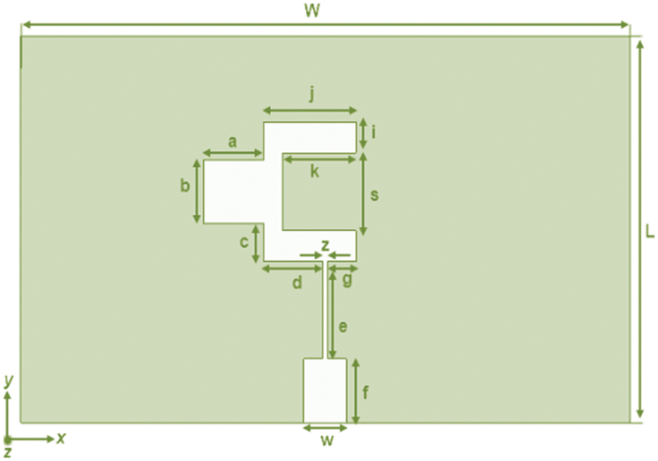
Figure 1: Layout of the 37 GHz antenna (front view)
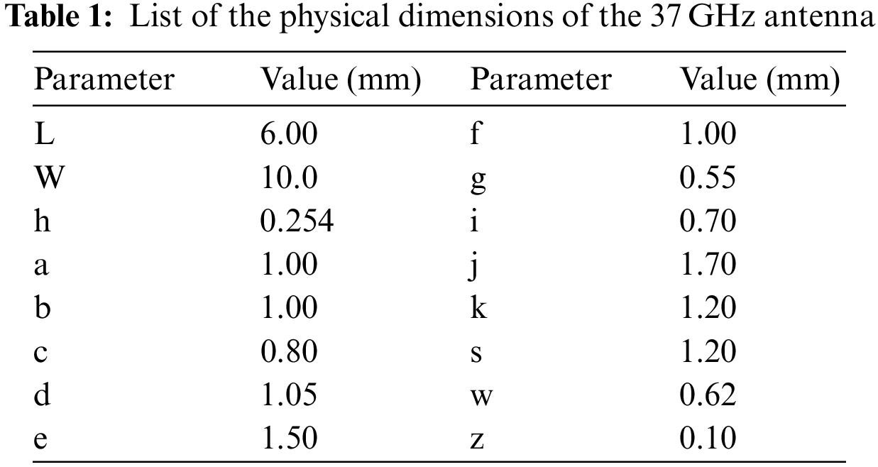
In Fig. 2, it is shown that how the proposed design (Fig. 1) is achieved by adopting several modifications in the basic layout of the patch antenna. The strips with dimesions of a × b = 1 × 1 mm2 are added to the left of the radiating patch and a slot with dimesions of k × s = 1.2 × 1.2 mm2 is inserted to the right side, makes the proposed design to operate at desired resonance frequency. To carefully chose the dimensions of the strips and slots, few design evaluation steps are performed as shown in Fig. 2a while the comparison among them in terms of return loss is depicted in Fig. 2b. As initially, a basic patch antenna does not yield a reasonable bandwidth considering −10 dB criteria at the desired 37 GHz band while successive improvements are achieved when the strips and slots are adopted in the patch antenna in step (ii) and (iii), respectively. Thus, it proves that the final geometry adopted in step (iii) is quite liable to give a satisfactory resonance at the 37 GHz band with an adequate bandwidth.
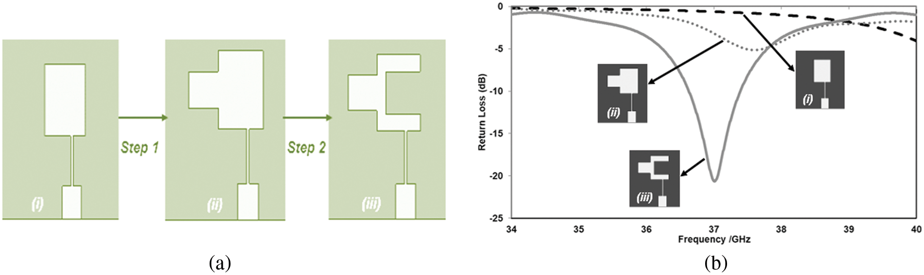
Figure 2: Design evolution and return loss comparison (a) design evolution; (b) return loss comparison
2.2 Array Structure of the Proposed Antenna
The single element antenna (Fig. 1) operates in 37 GHz gives a 6.84 dB peak gain, which is insufficient for 5G mobile phone and similar devices. The gain enhancement is necessary to ensure a good experience at the mm-wave transmission. For the gain enhancement, multiple techniques have been proposed by the researchers in the past [20–24]. The simplest way to enhance the gain of the microstrip antenna is by making the multiple element array of the individual elements [25]. Fig. 3 illustrates the structures of the 2 and 4-elements array antennas. In these structures the identical distribution of each individual element is used with the similar value of amplitude and phase. The stub like structure utilized in single element is removed by carefully adjusting the power divider structure connected with the array structure such that maximum radiation efficiency is ensured. This can be done by providing the similar impedance for each individual element. Each array element is connected to a 50 Ω characteristic impedance transmission line and is excited in such way that the power is equally distributed among them. To avoid mutual coupling between the elements, the spacing between them is kept in multiple of wavelengths, i.e., 0.5λ or 0.25λ. In the proposed model the separation among the neighboring elements is geared up to 1.9 mm. To attain the same phase, the length of the transmission line of each adjacent element is kept equal.
Figure 3: Structure of the array antenna (a) 2-elements; (b) 4-elements
The width of the transmission lines is calculated by using the following relationship [26].
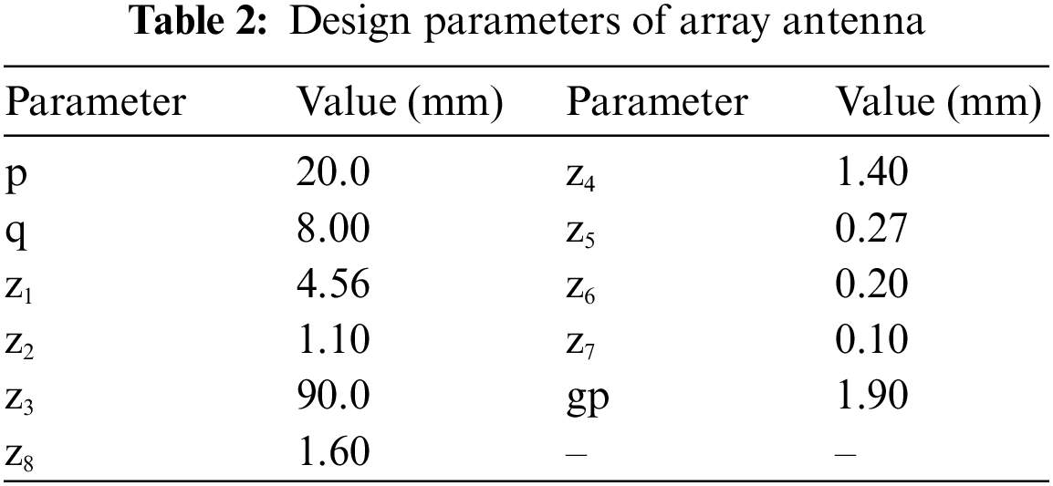
where, εr is the relative permittivity and Zc is the characteristic impedance of the feedline. The physical dimensions of the 37 GHz array antenna are summarized in Table 2.
This section presents the proposed antenna analysis under two separate conditions (i) Off-body and (ii) On-body. In both conditions the antenna performance is investigated in terms of return loss, Voltage Standing Wave Ratio (VSWR), radiation pattern, gain and surface electric fields, using CST MWS. The antenna is excited by a 50 Ω, K-type connector. The simulations are carried out using the open add space boundary condition around the antenna in the 34–40 GHz frequency span. Fig. 4 shows the measurement setup of the proposed 37 GHz array antenna in antenna measurement facility (anechoic chamber).
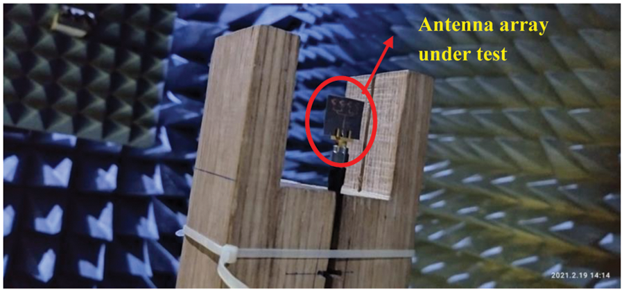
Figure 4: Proposed antenna array under testing
Fig. 5 reveals return loss comparison of the single element, 2 and 4-elements array antennas under off-body condition. The return loss is lower than −10 dB in each case. The antenna with single element has a minimum return loss of −22.24 dB at 37 GHz, and the 2 and 4-elements array antennas give a maximum return loss of −36.24 and −33.23 dB respectively at the resonant frequency. The −10 dB simulated bandwidth of the single element, 2 and 4-elements array antennas are 780, 653, and 677 MHz, respectively. The bandwidth is little bit reduced in case of the array strucutre due to the power divider structure, where to some extent losses are incurred which are not avoidable. Moreover, the little bit discrepancy between the simulated and measured results is due to the connector and fabrication tolerances.
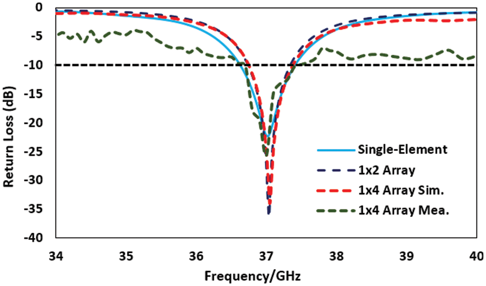
Figure 5: Off-body return loss comparison
The simulated radiation pattern of the antennas at 37 GHz in two orthogonal planes, i.e., E-plane (YZ, ϕ = 90°) and H-plane (XZ, ϕ = 0°) are displayed in Figs. 6a and 6b, correspondingly. The single element antenna gives a 6.84 dB peak gain and radiation efficiency of 91%. The 2-element array antenna consisted of two patch elements enhance the gain by around 3 dB and radiates with a boresight gain of 9.94 dB with a radiated efficiency of 98%. Further doubling the patch elements to four, enhanced the peak gain to 12.8 dB and the antenna radiates with a radiated efficiency of 98%.
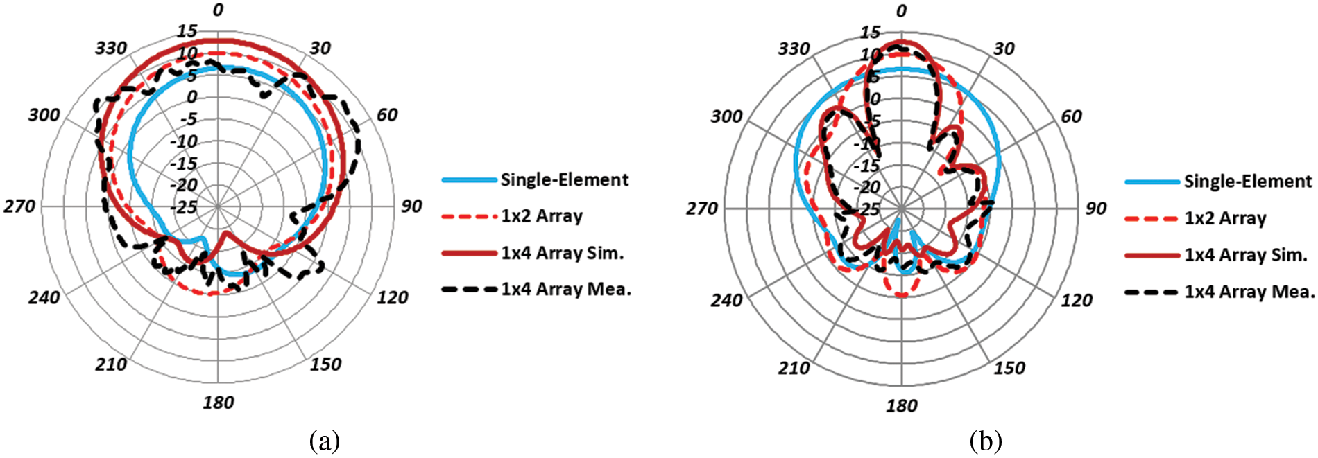
Figure 6: Comparation of radiation pattern at 37 GHz in the two orthogonal planes (a) E-plane; (b) H-plane
Moreover, the single element, 2, and 4-elements array antennas show a 3 dB beamwidth of {(93o, 81.5o), (81.1o, 37.9o), (80.8o, 20.6o)}, respectively in the E and H planes. It can also be analyzed that increasing the number of elements has reduced the side and back lobe level in both the principal planes. As the 4-elements array antenna fulfil the gain and bandwidth requirements for 5G mobile communication system, therefore, it is considered as a proposed model. The gain of the 37 GHz array antenna is indicated in Fig. 7a. The peak values of simulated and measured gain observed at 37 GHz, are 12.8 and 11.6 dB, respectively.
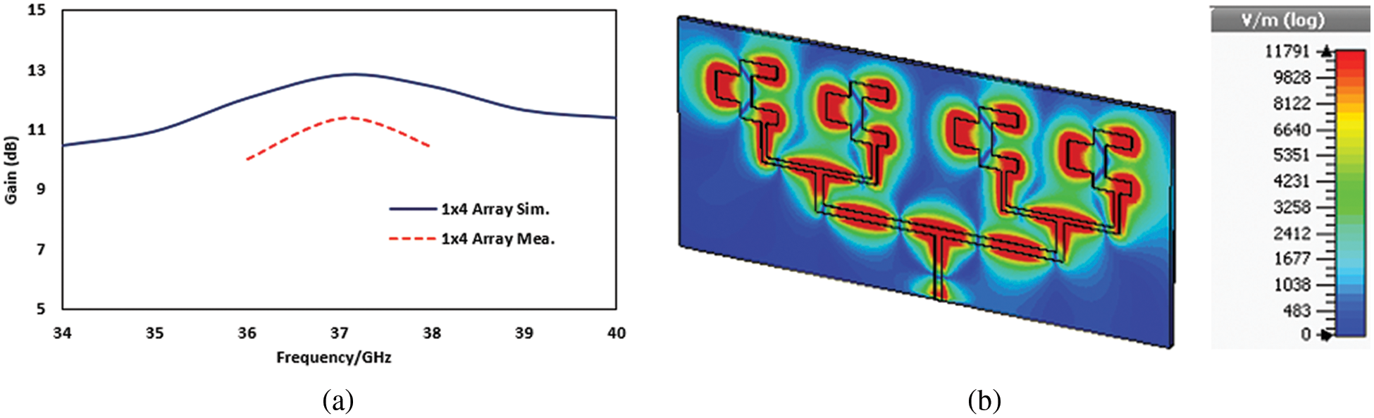
Figure 7: (a) Gain of the proposed antenna array, (b) Electric field of the proposed 4-elements antenna array
For more explanation Fig. 7b, demonstrates the surface Electric Fields (E-field) of the proposed 4-elements array antenna at 37 GHz. It is observed from the plot that at resonant (37 GHz) frequency, the entire 4-elements are radiating. Therefore, the whole effective length of the antenna contributes to radiations at this frequency.
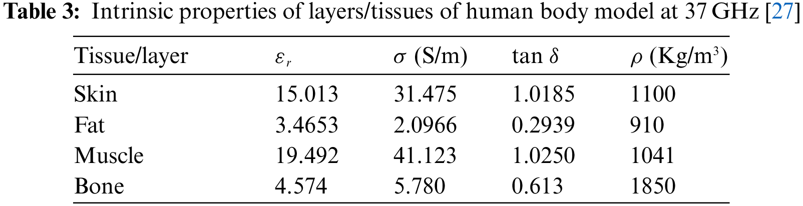
The mobile phone and similar devices are operating in the proximity of the human body, and due to the lossy nature of the biological tissues, antenna operation is badly implicated. Therefore, after on-body (free space) analysis of the antenna, this sub-section presents the performance of 5G antenna in the proximity of the human body at 37 GHz. Here, three models (belly, hand, and head) of the human body have been proposed, shown in Fig. 8. These models are modeled and simulated in CST MWS. The ‘belly’ model is made of three layers i.e., skin, fat, and a muscle; while the ‘hand’ model is comprised of four layers i.e., skin, fat, muscle and a bone. Each layer has their own specific thicknesses. The model shown in Fig. 8a presents a 2, 5 and 16 mm thicker skin, fat, and muscle layers respectively. The hand model shown in Fig. 8b is a four-layer model which presents a 2, 4, 10 and 4 mm thicker skin, fat, muscle, and bone layers, respectively. The length and width of these flat human body models (belly and hand) are 50 and 25 mm, respectively. Fig. 8c shows the approximate model of a human head which consists of three layers. A 2 mm thick skin layer, followed by muscle and skull layers with 2 and 6 mm thickness respectively. This model has been proposed by considering a sphere in CST MWS whose radius is given by the thicknesses of the different layers. Since all these layers are lossy in nature with complex biological structure, and different tissues having complex permittivity and conductivity. Therefore, it is very important to carefully characterize these tissues of which the model is comprised. Reference [27] was quite helpful to estimate the tissue properties. The intrinsic properties of the tissues are summarized in Table 3. For on-body simulations the antenna is in the locality of body models.
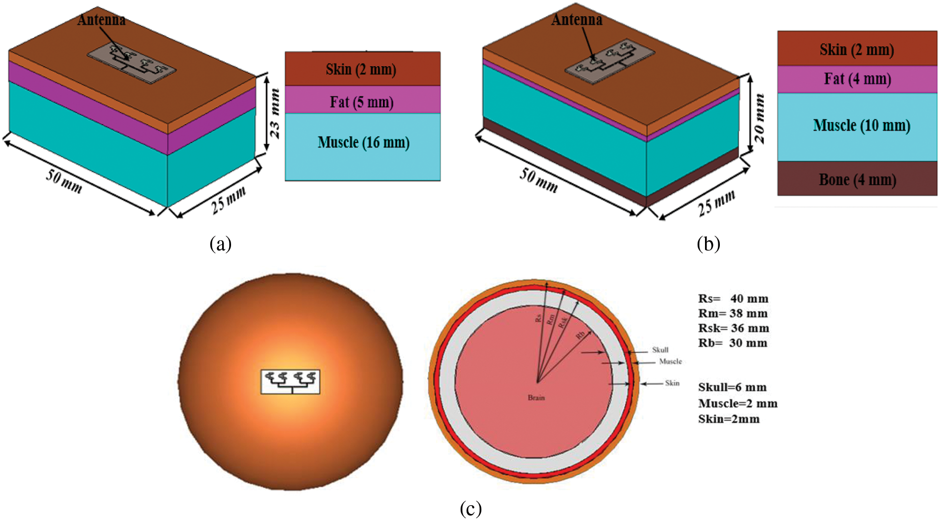
Figure 8: Antenna on human body models (a) Belly; (b) Hand; (c) Head
The simulated return loss of the proposed antenna in free space and in the locality of body is compared and presented in Fig. 9. This clearly shows that when the antenna is placed in the neighborhood of the body, the resonant frequency is slightly shifted in the direction of lower frequencies. This is due to the interaction of the antenna to the lossy human body and depends upon the dielectric constant and thickness of the material used. In addition, due to the conductivity of the uppermost layer skin of human body models an increase in the magnitude of the return loss has also been observed. According to the −10 dB criteria, the driving point impedance bandwidth of the antenna, in the vicinity of ‘belly’, is ranging from 36.44–37.90 GHz, which is equivalent to 654.75 MHz. In the case of human body model ‘hand’, the antenna operates in the frequency range of 36.43–37.09 GHz, corresponds to an impedance bandwidth of 656.78 MHz. Similarly, when the antenna is in the proximity of modelled human ‘head’, the antenna gives a bandwidth of 654.16 MHz. In comparison with the −10 dB bandwidth of the proposed 5G antenna in free space (36.63–37.41 GHz; 780 MHz), the same antenna gives a lower bandwidth when placed near the models of various parts of human body. Though the bandwidth of the on-body condition is lower than the off-body (free space) condition, but still the impedance bandwidth meets all the constraints of using the antenna for 5G wireless services.
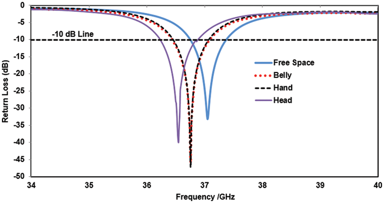
Figure 9: Simulated return loss of antenna in free space and in the presence of human body models
Fig. 10 shows the comparison of radiation pattern at 37 GHz, in both E-(YZ, ϕ = 90°) and H-(XZ, ϕ = 0°) planes, when the antenna is closed-proximity of human body. The radiation pattern of the antenna in the locality of the given models are affected by the lossy dielectric substances in terms of absorption and reflection (Fig. 10). In the E and H planes, it seems that overall back lobe radiations, is absorbed in the human body models. This is due to the high permittivity of the tissues that make up the models. It is also redirecting these back lobes in the forward direction, contributing an amplification in the main lobe magnitude, resulting greater boresight gain compared to the gain of the antenna operating in free space (off-body). The increase in the boresight gain results from the human body models work as a reflector, in the vicinity of the antenna. Maximum gain of the antenna on given models of human body, i.e., belly, hand and head are 12.8, 12.7 and 12.7 dB, correspondingly. The radiation efficiency of the antennas is 93.43%, 93.46% and 94.04% for the belly, hand, and head model, respectively. The radiation efficiency of the antenna in the proximity of human body models reduces around 5% compared to the radiation efficiency of the antenna in free space (98%). For more clarity the Three-Dimensional (3D) radiation pattern of the antenna mounted on human body models are portrayed in Fig. 11. These snaps prove that in each case the antennas radiate most of their power away from the human body models.
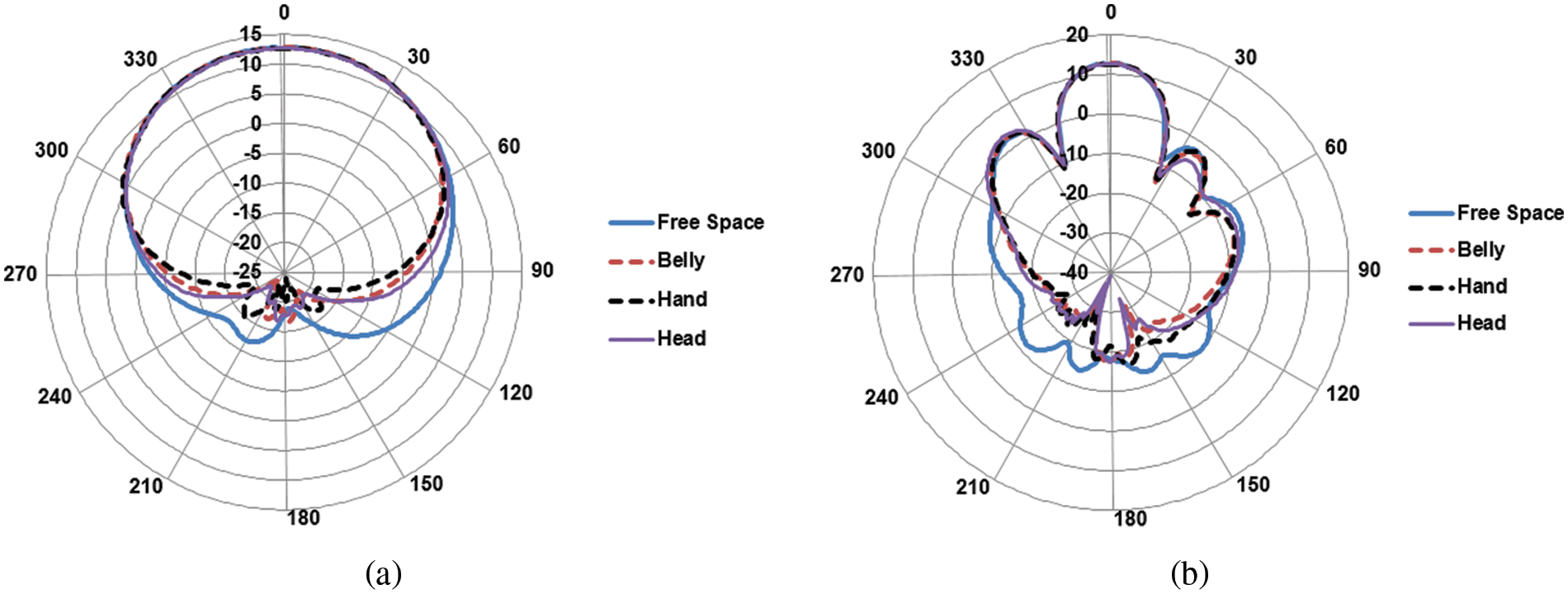
Figure 10: Comparison of simulated radiation pattern of the 37 GHz antenna in two orthogonal planes; (a) YZ-plane; (b) XZ-plane
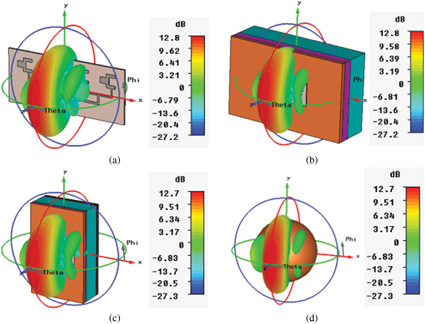
Figure 11: Simulated gain patterns of the proposed 4-elements array antenna; (a) Free space; (b) Belly; (c) Hand; (d) Head
4 Specific Absorption Rate (SAR) Analysis
The SAR analysis of 37 GHz antenna on various models of human body, i.e., belly, hand, and head, are presented in this section. The study of the SAR is carried out in CST MWS using the IEEE C95.3 averaging method. The SAR is calculated for an average mass of 10 g of biological tissue, considering the IEC standard, discussed earlier in Section 1. Fig. 12 shows the SAR of the proposed 4-elements array antenna on three various human body models (belly, hand, and head). The simulated results are normalized to 0.5-watt power.
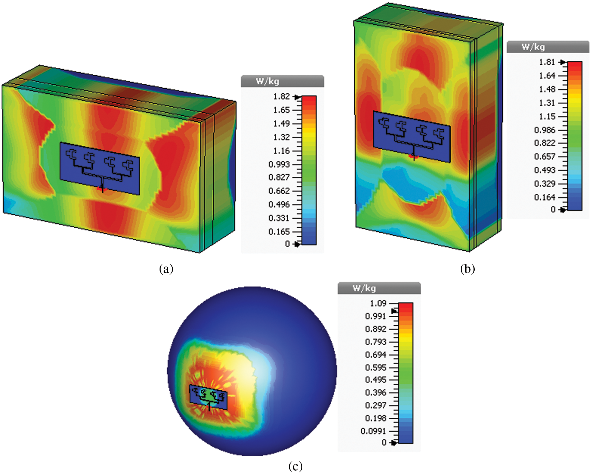
Figure 12: SAR distribution with the maximum input power of 0.5-watt, in; (a) Belly; (b) Hand; (c) Head
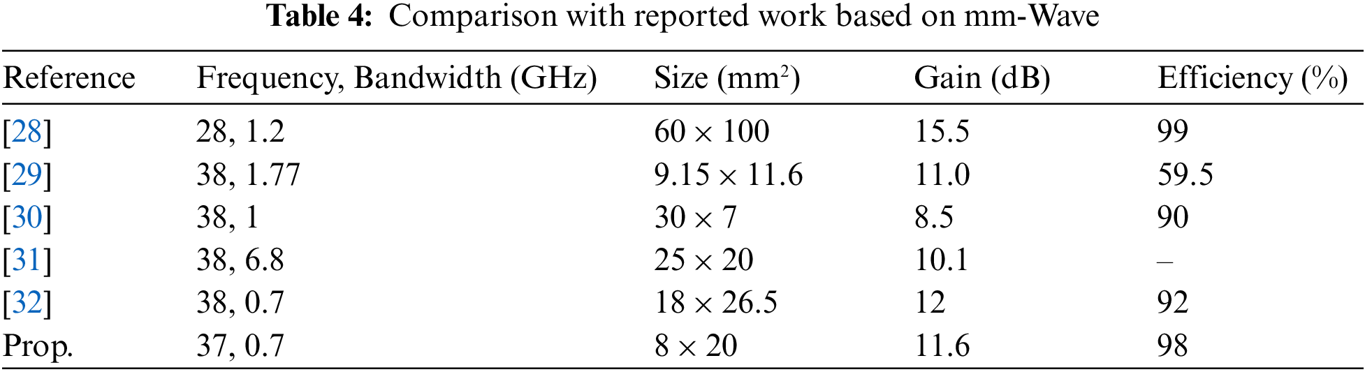
The calculated SAR values are, in three models (1.82, 1.81 and 1.09 W/kg, for the belly, hand and head, respectively), less than recommended by the IEC, at 2 W/Kg for any 10 g of biological tissue. Hence, the SAR of the proposed 4-elements array antenna lies in the safe limit of the IEC standard and can be potentially used in future 5G mobile communication. Table 4 provides a comparative assessment of the proposed design and the reference mmW antennas published the past. It is worthy to mention that a proposed design holds a significant privilege over the reported antennas in terms of operational −10 dB bandwidth, compactness, peak gain and radiation efficiency.
In this work a 37 GHz, planar array for 5G mobile communication systems was proposed. The impedance matching was obtained by using the transmission line and quarter wave transformation. The single, 2 and 4-elements array antenna were analyzed using CST MWS. The results demonstrate that a maximum gain of 6.84 dB is achieved from the single element antenna in 37 GHz frequency band. But the gain obtained was less than the required gain for 5G mobile phones and similar devices. Therefore, to obtain the desired gain the antenna with 2 and 4-elements array are designed, and it is analyzed that 4-elements array gives a peak gain of 11.6 dB i.e., measured with a bandwidth of 0.7 GHz. As the desired gain was achieved from the 4-elements array antenna and therefore was considered a proposed model. To study the antenna performance in free space and in the proximity of the human body, three models of the human body tissue (belly, hand, and head) were proposed. The dielectric properties and corresponding densities of the various layers at 37 GHz were considered for the three models. These models are evidenced to be precise enough to compute the return loss of the antenna. It can be evident from the return loss that, due to the lossy nature of human body tissue, the frequency of the antenna detunes from its resonant point. The radiation patterns, analyzed in the free space and in the proximity of the human body models, show a decrease in the back lobes. Also, the SAR analysis of the antenna on three models, i.e., belly, hand and head were calculated for an average mass of 10 g of tissues with an input power of 0.5-Watt, considering the IEC standard. It was observed that small amount of the EM waves is absorbed in the human body tissues, resulting the SAR values of 1.82, 1.81 and 1.09 W/kg, respectively, were lower than the international recommendations (2 W/kg). Hence, the SAR lies in the safe limit, and this was the projected and required characteristics, supporting the idea that the antenna can be potentially used for on-body connections. Thus, a proposed design becomes a potential candidate for 5G mobile phones and handheld devices.
Acknowledgement: The authors of the manuscript are grateful to research institute for microwave and millimeter wave studies (RIMMS), National University of Science and Technology (NUST), Islamabad for its support in the experimental validation of this work.
Funding Statement: The authors received no specific funding for this study.
Conflicts of Interest: The authors declare that they have no conflicts of interest to report regarding the present study.
References
1. H. Li, Y. Cheng and Z. Ling, “Design of distributed and robust millimeter-wave antennas for 5G communication terminals,” IEEE Access, vol. 8, pp. 133420–133429, 2020. [Google Scholar]
2. H. Chen, Y. Shao, Y. Zhang, C. Zhang and Z. Zhang, “A low-profile broadband circularly polarized mmWave antenna with special-shaped ring slot,” IEEE Antennas & Wireless Propag. Letters, vol. 18, pp. 1492–1496, 2019. [Google Scholar]
3. I. Ndip, T. H. Le, O. Schwanitz and K. D. Lang, “A comparative analysis of 5G mmWave antenna arrays on different substrate technologies,” in IEEE 22nd Int. Microwave and Radar Conf. (MIKON), Poznan, Poland, pp. 222–225, 2018. [Google Scholar]
4. Z. Lodro, N. Shah, E. Mahar, S. B. Tirmizi and M. Lodro, “mmWave novel multiband microstrip patch antenna design for 5G communication,” in IEEE 2nd Int. Conf. on Computing, Mathematics and Engineering Technologies (iCoMET), Sukkur, Pakistan, pp. 1–4, 2019. [Google Scholar]
5. A. N. Barreto, B. Faria, E. Almeida, I. Rodriguez, M. Lauridsen et al., “5G–Wireless communications for 2020,” Journal of Communication and Information Systems, vol. 31, no. 1, pp. 146–143, 2016. [Google Scholar]
6. N. Ojaroudiparchin, M. Shen and G. F. Pedersen, “Beam-steerable microstrip-fed bow-tie antenna array for fifth generation cellular communications,” in IEEE 10th European Conf. on Antennas and Propagation (EuCAP), Davos, Switzerland, pp. 1–5, 2016. [Google Scholar]
7. D. A. Sehrai, M. Abdullah, A. Altaf, S. H. Kiani, F. Muhammad et al., “A novel high gain wideband MIMO antenna for 5G millimeter wave applications,” Electronics, vol. 9, pp. 1031, 2020. [Google Scholar]
8. D. Ha, K. Baek, J. Lee, S. Park, J. H. Park et al., “Large scale array antenna packaging for 5G mmwave base station,” in IEEE 50th European Microwave Conf. (EuMC), Utrecht, Netherlands, pp. 45–48, 2021. [Google Scholar]
9. D. A. Sehrai, M. Asif, N. Shoaib, M. Ibrar, S. Jan et al., “Compact quad-element high-isolation wideband MIMO antenna for mm-wave applications,” Electronics, vol. 10, pp. 1300, 2021. [Google Scholar]
10. R. Przesmycki, M. Bugaj and L. Nowosielski, “Broadband microstrip antenna for 5G wireless systems operating at 28 GHz,” Electronics, vol. 10, no. 1, pp. 1, 2021. [Google Scholar]
11. A. Koutinos, G. Xanthopoulou, G. Kyriacou and M. Chryssomallis, “A reconfigurable polarization—Frequency supershape patch antenna with enhanced bandwidth,” Electronics, vol. 9, pp. 1166, 2020. [Google Scholar]
12. M. K. Shereen, M. I. Khattak and M. Al-Hasan, “A frequency and radiation pattern combo-reconfigurable novel antenna for 5G applications and beyond,” Electronics, vol. 9, pp. 1372, 2020. [Google Scholar]
13. K. Raheel, A. Altaf, A. Waheed, S. H. Kiani, D. A. Sehrai et al., “E-shaped H-slotted dual band mmWave antenna for 5G technology,” Electronics, vol. 10, pp. 1019, 2021. [Google Scholar]
14. V. Kumari, G. Sheoran and T. Kanumuri, “SAR analysis of directive antenna on anatomically real breast phantoms for microwave holography,” Microwave and Optical Technology Letters, vol. 62, pp. 466–473, 2020. [Google Scholar]
15. H. Li, A. Tsiaras and B. K. Lau, “Analysis and estimation of MIMO-SAR for multi-antenna mobile handsets,” IEEE Transactions on Antennas and Propagation, vol. 65, pp. 1522–1527, 2017. [Google Scholar]
16. H. Yalduz, T. E. Tabaru, V. T. Kilic and M. Turkmen, “Design and analysis of low profile and low SAR full-textile UWB wearable antenna with metamaterial for WBAN applications,” AEU-International Journal of Electronics and Communications, vol. 126, pp. 153465, 2020. [Google Scholar]
17. J. Bang and J. Choi, “A SAR reduced mm-wave beam-steerable array antenna with dual-mode operation for fully metal-covered 5G cellular handsets,” IEEE Antennas and Wireless Propagation Letters, vol. 17, pp. 1118–1122, 2018. [Google Scholar]
18. J. Khan, S. Ullah, U. Ali, F. A. Tahir, I. Peter et al., “Design of a millimeter-wave MIMO antenna array for 5G communication terminals,” Sensors, vol. 22, pp. 2768, 2022. [Google Scholar]
19. C. A. Ballanis, Antenna Theory Analysis and Design. New York: John Willey and Son’s Inc., 2016. [Google Scholar]
20. W. Jiang, Y. Cui, B. Liu, W. Hu and Y. Xi, “A dual-band MIMO antenna with enhanced isolation for 5G smartphone applications,” IEEE Access, vol. 7, pp. 112554–112563, 2019. [Google Scholar]
21. S. Das and D. Mitra, “A compact wideband flexible implantable slot antenna design with enhanced gain,” IEEE Transactions on Antennas and Propagation, vol. 66, pp. 4309–4314, 2018. [Google Scholar]
22. B. J. Vaughn, “Novel gain enhancement technique for microstrip patch antennas based on multi-pronged feed network synthesis,” Doctoral Dissertation, Purdue University, 2016. [Google Scholar]
23. J. Khan, D. A. Sehrai, M. A. Khan, H. A. Khan, S. Ahmad et al., “Design and performance comparison of rotated Y-shaped antenna using different metamaterial surfaces for 5G mobile devices,” Comput. Mater. Contin., vol. 2, pp. 409–420, 2019. [Google Scholar]
24. F. Oktafiani and Y. N. Wijayanto, “Analysis of printed patch antenna array for 37 GHz point-to-point wireless links,” in IEEE 22nd Asia-Pacific Conf. on Communications (APCC), Yogyakarta, pp. 379–382, 2016. [Google Scholar]
25. Y. N. Wijayanto, A. Kanno, H. Murata, T. Kawanishi, N. Yamamoto et al., “Array of patch-antennas with meandering-gaps on optical modulator for wireless millimeter-wave beam-steering,” International Journal of Microwave and Wireless Technologies, vol. 8, pp. 759–765, 2016. [Google Scholar]
26. M. Kamal, S. Yang, S. Kiani, D. Sehrai, M. Alibakhshikenari et al., “A novel hook-shaped antenna operating at 28 GHz for future 5G mmwave applications,” Electronics, vol. 10, pp. 673, 2021. [Google Scholar]
27. http://niremf.ifac.cnr.it/tissprop/, Accessed: 25 December 2021. [Google Scholar]
28. A. Khabba, S. Ibnyaich and M. M. Hassani, “Beam-steering millimeter-wave antenna array for fifth generation smartphone applications,” in IEEE Int. Conf. of Computer Science and Renewable Energies (ICCSRE), Agadir, Morocco, pp. 1–5, 2019. [Google Scholar]
29. Y. -X. Sun, D. Wu, X. S. Fang and N. Yang, “Compact quarter-mode substrate-integrated waveguide dual-frequency millimeter-wave antenna array for 5G applications,” IEEE Antennas and Wireless Propagation Letters, vol. 19, no. 8, pp. 1405–1409, 2020. [Google Scholar]
30. A. Sohail, H. Khan, U. Khan, M. I. Khattak, N. Saleem et al., “Design and analysis of a novel patch antenna array for 5G and millimeter wave applications,” in IEEE 2nd Int. Conf. on Computing, Mathematics and Engineering Technologies (iCoMET), Sukkur, Pakistan, pp. 1–6, 2019. [Google Scholar]
31. Y. Rahayu and M. I. Hidayat, “Design of 28/38 GHz dual-band triangular-shaped slot microstrip antenna array for 5G applications,” in IEEE 2nd Int. Conf. on Telematics and Future Generation Networks (TAFGEN), Kuching, Malaysia, pp. 93–97, 2018. [Google Scholar]
32. J. Khan, D. A. Sehrai and U. Ali, “Design of dual band 5G antenna array with SAR analysis for future mobile handsets,” Journal of Electrical Engineering & Technology, vol. 14, pp. 809–816, 2019. [Google Scholar]
Cite This Article
 Copyright © 2023 The Author(s). Published by Tech Science Press.
This work is licensed under a Creative Commons Attribution 4.0 International License , which permits unrestricted use, distribution, and reproduction in any medium, provided the original work is properly cited.
 Downloads
 Citation Tools