
 Submit a Paper
 Propose a Special lssue
 Open Access
ARTICLE

Image Inpainting Technique Incorporating Edge Prior and Attention Mechanism
College of Information Engineering, Xizang Minzu University, Xianyang, 712000, China
* Corresponding Author: Yao Fan. Email:
(This article belongs to the Special Issue: Advances and Applications in Signal, Image and Video Processing)
Computers, Materials & Continua 2024, 78(1), 999-1025. https://doi.org/10.32604/cmc.2023.044612
Received 04 August 2023; Accepted 24 November 2023; Issue published 30 January 2024
 View Full Text
 Download PDF
Abstract
Recently, deep learning-based image inpainting methods have made great strides in reconstructing damaged regions. However, these methods often struggle to produce satisfactory results when dealing with missing images with large holes, leading to distortions in the structure and blurring of textures. To address these problems, we combine the advantages of transformers and convolutions to propose an image inpainting method that incorporates edge priors and attention mechanisms. The proposed method aims to improve the results of inpainting large holes in images by enhancing the accuracy of structure restoration and the ability to recover texture details. This method divides the inpainting task into two phases: edge prediction and image inpainting. Specifically, in the edge prediction phase, a transformer architecture is designed to combine axial attention with standard self-attention. This design enhances the extraction capability of global structural features and location awareness. It also balances the complexity of self-attention operations, resulting in accurate prediction of the edge structure in the defective region. In the image inpainting phase, a multi-scale fusion attention module is introduced. This module makes full use of multi-level distant features and enhances local pixel continuity, thereby significantly improving the quality of image inpainting. To evaluate the performance of our method, comparative experiments are conducted on several datasets, including CelebA, Places2, and Facade. Quantitative experiments show that our method outperforms the other mainstream methods. Specifically, it improves Peak Signal-to-Noise Ratio (PSNR) and Structure Similarity Index Measure (SSIM) by 1.141~3.234 db and 0.083~0.235, respectively. Moreover, it reduces Learning Perceptual Image Patch Similarity (LPIPS) and Mean Absolute Error (MAE) by 0.0347~0.1753 and 0.0104~0.0402, respectively. Qualitative experiments reveal that our method excels at reconstructing images with complete structural information and clear texture details. Furthermore, our model exhibits impressive performance in terms of the number of parameters, memory cost, and testing time.Keywords
Image inpainting is a challenging computer vision task that aims to construct visually appealing and semantically plausible content for missing regions. It has various practical applications, including restoring damaged photos [1], removing unwanted objects [2], and enhancing image resolution [3]. Initially, traditional diffusion-based methods [4,5] were used for image inpainting. These methods gradually spread pixel information into the surrounding areas of damaged regions and synthesize new textures to fill the holes. While effective for repairing small damaged areas like cracks, these methods tend to produce blurry results as the size of the missing regions grows. Pioneering sample-based methods were then developed for image inpainting [6,7] which synthesize texture by searching for matching similar sample blocks in the undamaged areas of the image and copying them to the corresponding positions in the missing regions. These approaches often produce high-quality texture but may introduce incorrect structure and semantics in the restoration.
With the rapid advancement of deep learning in image processing tasks, researchers worldwide have introduced various deep learning techniques to tackle these challenges. Convolutional neural networks (CNNs) [8–10] have been widely adopted in methods that follow an encoder-decoder architecture and incorporate the adversarial idea of generative adversarial networks (GANs) [11]. These methods aim to reconstruct missing regions by learning high-level semantic features. Nonetheless, the localized inductive bias of convolutional operations and the limited receptive field make it difficult for the model to learn globally consistent textures in semantics. To address these limitations, attention mechanisms have been introduced in methods [12,13] to find the most similar feature blocks to the masked regions in the feature space of known regions. This enables long-distance feature block matching. However, for images with large missing regions, the attention mechanism cannot provide sufficient information for restoration, resulting in blurred texture details and increased artifacts in the restoration results. In comparison to CNN-based methods, transformer-based solutions [14,15] leverage the strengths of transformers in capturing long-term correlations and extracting global features to reconstruct low-resolution images and then provide CNN-based upsamplers to restore texture details. Nonetheless, the above restoration scheme ignores the significance of the overall image structure, resulting in inconsistent boundaries and a lack of semantics in the results. Moreover, there are high computational and storage costs associated with model training and inference processes. Some methods use edge [16], gradient [17], or semantic [18,19] information for structural restoration. For example, Nazeri et al. [20] utilized the Canny operator to extract edge information from the defective region. Subsequently, the refinement network utilizes the reconstructed edge maps as structural information to guide the content repair continuously, which enhances the repair of structural details to a certain extent. Differently, Xiong et al. [21] utilized predicted foreground contour maps to guide image completion, ensuring the rationality of image content filling and avoiding overlap with foreground objects. However, the above inpainting methods based on structural constraints have certain limitations. Firstly, due to the spatial invariance and local induction priors of convolutional neural networks, they may not perform well in understanding global structures, leading to subpar edge prediction results. Secondly, many factors influence successful texture synthesis in image inpainting. While focusing on structural details is important, successful texture synthesis also requires the effective utilization of long-range features to capture rich contextual information.
To address these issues, this paper presents a two-stage image inpainting framework that combines edge prior and attention mechanism (EPAM). Our framework uses the transformer architecture to accurately predict the edge structure of the defect area. Then in the image inpainting stage, effective edge structures are used to constrain the image content, so as to reconstruct visually plausible and texture-clear images.
In summary, the contributions of this paper are as follows:
(1) In the edge prediction phase, this paper proposes an efficient transformer-based edge prediction (TEP) module to accurately extract edges of incomplete regions. Unlike existing CNN-based methods, our TEP module achieves more accurate and comprehensive structural restoration. In the TEP module, axial attention with relative position encoding is used. This improves position awareness while significantly reducing computational complexity, ensuring a balance between performance and efficiency.
(2) In the image inpainting phase, a multi-scale fusion attention (MFA) module is designed. This module aggregates contextual feature information at different levels using dilated convolutions with varying ratios. Additionally, an efficient channel attention mechanism is applied to reduce the impact of redundant features. Furthermore, the attention transfer network is introduced to fully integrate shallow texture details and deep semantic features, thereby avoiding unreasonable or contradictory regions in generated images. This allows our model to accurately reconstruct texture details under the guidance of the edge structure.
(3) Experiments are carried out by comparing the EPAM model to existing state-of-the-art approaches. The EPAM model demonstrates superior performance in both qualitative and quantitative assessments, as observed in the CelebA [22], Facade [23], and Places2 [24] datasets.
In recent years, many methods have been proposed to improve the results of image inpainting by incorporating prior knowledge of image structure. For example, Liao et al. [25] built upon the CE [8] and introduced an edge-aware context encoder to predict the image edge structure. This approach facilitated the learning of scene structure and context. However, the inpainted regions in their results often suffered from significant blurring and artifacts. Cao et al. [26] utilized an encoder-decoder structure to learn a sketch tensor space composed of edges, lines, and connection points. They also introduced a gated convolution and attention module to enhance local details under cost-saving conditions. However, this design is not suitable for structural restoration in facial or similar scenes. Some methods have also attempted to incorporate both image structure and texture details to guide image completion. For example, Liao et al. [19] designed a semantic segmentation guidance and evaluation mechanism to interact to iteratively update semantic information and repair images. Nonetheless, obtaining accurate semantic information for images with complex backgrounds can be challenging. Guo et al. [16] proposed a method that shares information between the two branches of texture generation and structure prediction. They also fused an attention module with learnable parameters to further enhance global consistency. Nevertheless, when applied to recover natural images with irregular defects, such coupled methods often lack explicit structural details.
Transformer [27] was originally proposed as a sequence-to-sequence model for machine translation tasks and was later improved and applied to computer vision tasks such as object detection, video processing, and image processing [28]. Researchers have recently started exploring the use of transformers for image restoration problems. Wan et al. [14] were among the first to use transformers for image inpainting. They employed bi-directional attention and a masked language model objective similar to BERT [29] to reconstruct low-resolution images with diverse appearances. Zheng et al. [30] designed a mask-aware transformer content reasoning model, which uses a restricted convolutional neural network module to extract tokens. In this model, the transformer encoder uses a replacement weighted self-attention layer to capture the global context, reducing Proximity dominant effects that give rise to semantically incoherent results. Nevertheless, this method cannot understand and imagine high-level semantic content.
The existing image inpainting methods based on structural constraints ignore the positive influence of long-distance features when dealing with large-area irregular defects. Once the reconstructed structure is missing or incorrect, the repair effect obviously deteriorates. It is worth noting that the above transformer-based methods primarily focus on image reconstruction to obtain low-resolution repaired images. However, one limitation of such methods is their long inference time, which can be a drawback in practical applications. For the structural reconstruction problem, edge maps are preferred over smooth or semantic images as they provide accurate structural information of images and have stronger resistance to noise and other interference factors. This paper therefore introduces a novel TEP module that uses the transformer to reconstruct the overall edge structure of an image. The TEP module outperforms CNN-based methods in terms of performance. To address the issue of artifacts in the restoration results, where texture details and inconsistent boundaries, this paper proposes the MFA module. This module enhances the texture inference ability and independently synthesizes new content in regions lacking structural information by mining distant features at different levels. In general, the EPAM model performs structure prediction and texture generation for images by decoupling, which improves the model’s representational ability and ensures the consistency of the overall structure and detailed texture of the restored images.
This paper proposes an image inpainting model that combines structural priors and attention mechanisms. The overall model architecture is shown in Fig. 1. The model consists of two cascaded generative adversarial networks (GANs), where the output of the first-stage generator serves as the input of the second-stage generator. These two-stage networks together form an end-to-end inpainting model. In the first stage, the edge prediction network utilizes grayscale inpainted images and incomplete edge information to predict plausible edge contours within the defect regions. Subsequently, the second-stage network utilizes the edge prediction map as a structural prior along with the incomplete RGB image to synthesize suitable texture details within a locally enclosed region surrounded by edges. This process ultimately completes the inpainting task.

Figure 1: Overall network structure. Our proposed EPAM is made up of two sub-networks. The upper half is the edge prediction network, and the lower half is the image inpainting network
In the edge prediction stage, the autoencoder serves as the generator of the edge prediction network, while the PatchGAN architecture is the discriminator. In view of this, this paper proposes the transformer-based edge prediction (TEP) module, which is embedded into the information bottleneck section of the autoencoder. Notably, instead of using deeply stacked convolutional layers, the TEP module uses a transformer-based architecture that allows all visible pixels to have equal flow opportunities, resulting in expressive global structures. In addition, relative position encoding [31] and axial attention blocks [32] are introduced into the TEP module, to enhance spatial relations and reduce memory overhead. Existing attention-based models often suffer from color discrepancies, blurriness, and boundary distortions in the inpainted images. To address these issues, the Multi-scale Fusion Attention (MFA) module is introduced. Cascaded MFA modules are integrated after the encoder. The MFA module captures deep features in different receptive fields by using dilated convolution with varying expansion rates so as to better integrate global contextual information with local details. Then, an Attention Transfer Network (ATN) [33] is constructed on feature maps at four scales to enhance local pixel continuity and make effective use of long-distance dependencies, which notably improves the quality of image inpainting.
The edge prediction network contains a generator
where
Finally, the inpainting output with the same original size is obtained by using Eq. (3).
3.1.1 Transformer-Based Edge Prediction Module
The transformer architecture was originally used to solve natural language processing (NLP) tasks. This architecture is entirely based on self-attention and can directly model longer-distance dependencies between input sequences. Recently, researchers have applied it to computer vision tasks and achieved remarkable results. Inspired by ViT [34], this paper introduces the transformer decoder from [27] into the TEP module and then reconstructs the edge information based on the shallow features of the encoder’s output.
In Fig. 2, the input feature of the TEP module is represented as

Figure 2: Architecture of the proposed transformer-based edge prediction (TEP) module
To reduce the consumption of feature map computation and storage in the self-attention layer, both the axial attention module and the standard attention module were introduced in the TEP module. Axial attention modules can be implemented by reshaping tensors on the width and height axes, which are then processed with dot-product-based self-attention, respectively. As shown in Fig. 3, uni-directional attention only focuses on the contextual constraints before the token. Although bi-directional attention can pay attention to all positions before and after the token, its computational complexity up to is

Figure 3: Differences between uni-directional, bi-directional and axial attention
The attention weights are obtained by Softmax operation. The output
Then, the layer
In addition, the standard attention module
3.1.2 Design of Edge Generator and Discriminator
The edge generator in this paper follows a self-encoder structure to predict edges through encoder data compression, bottleneck layer feature reconstruction, and decoder decompression for a given image feature
To improve the network’s attention to local details during training, the PatchGAN [36] architecture is used as the basic framework of the edge discriminator. It consists of 5 layers of convolution with strides of 2, 2, 2, 1, 1 and a kernel size of 4 × 4. Spectral normalization [37] and the Leaky-ReLU activation function are applied after each convolutional layer. After 5 layers of convolution operations, the input image is converted into a single-channel feature map with dimensions of 30 × 30. Ultimately, the Sigmod function is used to map the output to a scalar in the range of [0, 1], which can effectively distinguish the authenticity of the input samples and promote the generation of high-quality restoration results.
3.2.1 Multi-Scale Fusion Attention Module
In the texture synthesis stage, traditional methods often extract feature information from shallow details to high-level semantics through convolutional layer stacking. However, this approach has limitations. The extraction of rich spatial structural information and texture details is performed serially with a fixed-size convolutional kernel, leading to varying degrees of feature loss. This also exacerbates inconsistency in global contextual information and causes difficulty in capturing global structural information from distant pixels. To address this problem, the MFA module is introduced. It first extracts information at different scales in parallel by applying convolution operations with different expansion factors to the input features. Then, the features at each scale are scaled and fed into the ATN module to facilitate the transfer of information between features at different levels. This helps the model to better understand the details and structures in the image, resulting in improved restoration quality and accuracy. In addition, the utilization of efficient channel attention [38] and pixel attention [39] enables the model to selectively focus on important channels and pixels, thus reducing unnecessary computations and parametric quantities. The residual structure and skip connections help to avoid gradient explosion and network convergence difficulties. See Fig. 4 for details.

Figure 4: Architecture of the proposed multi-scale fusion attention (MFA) module
Specifically, a 1 × 1 convolution operation is used to transform the dimension of the input feature
Subsequently, Parallel expansion convolution is used to extract multilevel features
Since deep feature maps are usually more compact, scaling is applied to the features of each layer.
Then, Attention Transfer Network (ATN) [33] is introduced to guide the complementation of low-level features layer by layer from high-level features, which makes the complementation content semantically sound and texture clear.
Local residual connections are built on the feature map of the last ATN reconstruction to reduce information loss. After 3 × 3 convolution,
In addition, to ensure the consistency of local contextual feature information, operations such as skip connection and 3 × 3 convolution are employed to fuse multilevel features
3.2.2 Design of Image Generator and Discriminator
Image generators are an improvement over autoencoders. Since the bottleneck layer does not use the transformer structure, inputting a large-size feature map into the bottleneck layer will not cause excessive computational complexity. In this case, the encoder only downsamples to a feature map dimension of 64 × 64 × 256. To synthesize realistic textures in different regions, the bottleneck layer employs stacked 4 MFA modules instead of fully connected layers. Through hierarchical atrous convolutions and attention transfer strategies, the generator is able to synthesize semantically correct new content independently even in the absence of local edge information. Otherwise, the image generator has the same network structure and parameter settings as its counterpart in the edge generator.
The image discriminator has a similar structure to the edge prediction discriminator. It uses a 70 × 70 PatchGAN discriminator network, which consists of five layers of convolutions with a kernel size of 4 × 4. The discriminator network performs spectral normalization and Leaky-ReLU activation function processing after each layer of convolution operation. The output of the last layer is a two-dimensional matrix of
3.3.1 Loss of Edge Prediction Network
To obtain a clear and realistic edge prediction map, the edge prediction network uses a joint loss for model training, including adversarial loss [11] and feature matching loss [40]. Given the mathematical expectation
The feature matching loss
Let the loss weights
3.3.2 Loss of Image Inpainting Network
To ensure the image inpainting result has reasonable semantic content, consistent structure, and clear texture, this paper uses various loss functions including adversarial loss, perceptual loss [41], style loss [42], and reconstruction loss to train the image inpainting network. The network uses Eq. (19) to represent the adversarial loss
Next, the pre-trained VGG-19 [43] network is adopted to convert the differences between the pixel values of the repaired image
Style loss usually uses the Gram matrix (gram) to calculate the difference of feature maps, expressing the correlation of style features on different channels, so that the inpainted image is closer to the reference image’s style. Let
The reconstruction loss
The total loss
4.1 Experimental Design and Implementation
The experimental hardware configuration in this paper is a single Intel(R) Core i7-11700 CPU, a single NVIDIA GeForce RTX 3090 24 GB GPU, 64.0 GB RAM, and the software environment is Windows 10, Pytorch v1.7.0, CUDA v11.0.
Training and evaluation were conducted on 3 publicly available datasets: CelebA [22], Facade [23], and Places2 [24]. The CelebA dataset contains 202,599 face images of celebrities and was commonly used in face-related computer vision experiments. The Places2 contains various unique scene categories, such as restaurants, beaches, courtyards, valleys, etc. The Facade dataset mainly consists of highly structured facades of cities worldwide. The distribution of the dataset in this paper is shown in Table 1. In terms of irregular masks, the test set of the irregular mask dataset proposed by Liu et al. [44] is adopted, which contains 12,000 masks equally divided into 6 intervals. During the experiments, images were randomly masked using the mask test set with different scale ranges. All images and irregular masks were resized to 256 × 256 pixels.

Referring to the parameter settings of the EC model, Both the two-stage network are trained with Adam optimizer (

For the weights of different loss terms in the two-stage model, this paper adjusted one weight at a time for comparison experiments based on the parameter settings of the EC method. Specifically, the network restarted training after adjusting the weight parameters each time. After 500 epochs, the model ends training and is saved. Eventually, the loss weights

Figure 5: Comparison of loss function weights of edge prediction network
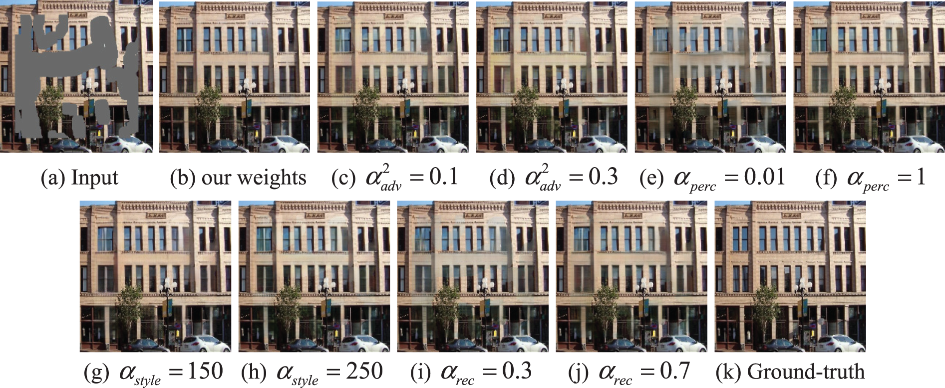
Figure 6: Comparison of loss function weights of image inpainting network
The training of the EPAM model involved three steps. First,
Fig. 7 shows the training loss plot of the proposed model on the Places2 dataset. Throughout the training process, the loss values of the latest batch of data were recorded every 5000 iterations. Both phases of the network underwent 2 million iterations each. Due to the large span of each loss value in the network, the red area of the curve was enlarged for better visualization. Fig. 7a shows the variation tendency of different loss functions during the training of the edge prediction network. The adversarial loss of

Figure 7: Two-stage training loss line charts of the EPAM model
4.2 Experimental Results and Analysis
To quantitatively evaluate the efficiency of the proposed EPAM model, this model is compared with some of the advanced inpainting algorithms, including EC [20], CTSDG [16], ICT [14], MAT [45], and PUT [46]. To reflect the generalization of the proposed method, irregular masks, center rectangle masks, and human-labeled masks are randomly used to perform occlusion experiments on samples for qualitative comparison. In addition, extensive quantitative comparisons, ablation studies, and visualization analysis are conducted to demonstrate the effectiveness of TEP and MFA.
4.2.1 Quantitative Comparisons
Four commonly used metrics are applied to evaluate the inpainting results of the proposed method and other methods for comparison. Peak Signal-to-Noise Ratio (PSNR) is a widely used objective measurement for image quality, although its results may not align perfectly with human perception. Structure Similarity Index Measure (SSIM) uses use three factors in line with human perception to evaluate the similarity between images, namely brightness, contrast, and structure. The window size used for SSIM calculation is set to 51. Learning Perceptual Image Patch Similarity (LPIPS) [47] is a perception-based metric that quantifies the differences between images and can better reflect human perception and understanding of images. Mean Absolute Error (MAE) refers to the average absolute errors between two values. The evaluation scores of our method with those of state-of-the-art approaches on datasets with irregular mask ratios of 20%–40%, 40%–60%, and random masks.
Table 3 presents the evaluation results on the CelebA dataset, where our model achieves the highest scores in both PSNR and SSIM. However, in some cases, our model may not rank as high in terms of LIPIPS and MAE. This discrepancy can be attributed to the use of dilated convolutions with different expansion factors to capture multi-scale context information and long-distance feature information of the defect image. The excessive zero-padding operation of the dilated convolution introduces certain edge artifacts in the patched image, which may affect these indicators. Distinct from other metrics, LPIPS compares the Euclidean distance between the repaired image and the feature representation of the real image obtained at an intermediate layer of a deep neural network. Therefore, there may be some similarities that cannot be captured by LPIPS, resulting in bias at the metric level. On the Facade dataset, our algorithm outperforms other methods by a significant margin in the first two metrics. This indicates that our algorithm is more effective in repairing fine structural details when dealing with highly structured objects. On the Places2 dataset, even though both PUT and MAT use the transformer architecture, our method consistently achieves superior performance across various metrics. This demonstrates the effectiveness of the proposed transformer-based edge prediction strategy and the multi-scale fusion attention strategy in improving the overall performance of the model.

The EPAM model is compared with existing methods on the CelebA dataset containing face images with similar semantics. As shown in Fig. 8, EC [20] is an inpainting method that starts with structure and then texture. However, the structure prediction in the previous step is incomplete, which will affect the detail restoration in the latter step. This results in blurry edges and unclear texture, as seen in the eyes and lips of the characters in rows 1 and 5 in Fig. 8b. CTSDG attempts to balance texture and structure generation, but it often fails to achieve a good balance, leading to local boundary artifacts. For example, the mouth of the face image in Fig. 8c exhibits distortion and missing parts, and the eyes do not appear natural enough.

Figure 8: Qualitative comparison results of our method with existing methods on the CelebA dataset with irregular and artificially drawn holes
ICT employs a transformer to reconstruct the visual prior and then uses conventional CNN to fill in texture details. However, the large-scale downsampling in this process causes the loss of important semantic information in the generated results. This is evident in the repaired eyes in Fig. 8d, which are either missing or deformed. MAT addresses large missing areas using a mask perception mechanism but falls short in dealing with small missing areas. For example, the eyes in rows 2, 4, and 5 in Fig. 8e are asymmetrical and inconsistent in size. PUT improves image quality using a non-quantized transformer, but it cannot fully understand the semantic features. For example, in Fig. 8f, the repaired eyeball part does not match the face. In comparison, our method excels in understanding global semantics and preserving more realistic texture details. It generates structurally and color-consistent face images, as shown in Fig. 8g.
The effect of our method on the Facade dataset is visually analyzed, and the results are shown in Fig. 9. When EC faces a large-scale rectangular defect, the windows of the building will be missing, resulting in noticeable color discrepancies in the restoration results. The visualization results of CTSDG demonstrate its inability to handle large holes, leading to the loss of essential components and image distortion. While ICT recovers occluded regions at the pixel level, it fails to capture the global structural semantics well. This can be observed in the irregularities of the windows and their surrounding contours in rows 1 and 2 of Fig. 9d. MAT utilizes long-range context to reconstruct structures and textures. However, the reconstructed masked regions in row 2 of Fig. 9e exhibit incoherent colors and unreasonable semantic objects. Although the image synthesized by PUT (Fig. 9f) appears to produce reasonable results, it is plagued by noticeable artifacts. In contrast, our model not only infers reasonable structural-semantic information but also effectively alleviates mesh artifacts and loss of texture information in local regions, thereby enhancing perceptual quality. For example, in rows 1 and 2 of Fig. 9g, the window edges repaired by our method exhibit clear outlines and visually appealing results. In addition, the small windows predicted by the mask area in row 3 are arranged regularly and possess reasonable semantics.

Figure 9: Qualitative comparison results of our method with existing methods on the Facade dataset with irregular, center-regular and artificially drawn holes
Our model is further evaluated on the Places2 dataset containing images with different semantics, as shown in Fig. 10. In such challenging scenarios, the structure-texture-based methods such as EC [20] and CTSDG [16] cannot understand the global background well, resulting in incomplete and unreasonable restorations. In contrast, methods using the Transformer architecture (ICT, MAT, and PUT) demonstrate improved capability in capturing global context information for complex image inpainting tasks. Nevertheless, due to the lack of constraints on global structural information, these methods often exhibit boundary inconsistencies and missing semantics in the inpainting results. This can be observed in column 6 of Fig. 10, where the target structure for occluded region reconstruction appears incoherent. In comparison to the above methods, our method incorporates a Transformer-based structure repair module that reconstructs the semantic content accurately. Additionally, our method employs an attention shift strategy, applied layer by layer to the MFA module, to combine shallow detail texture information and deep structural-semantic information based on a precise appearance prior. This strategy mitigates the loss of long-distance features in deep networks and greatly enhances the consistency between global and local features of the image. For example, rows 1–4 in Fig. 10g show high-quality texture and structural details in missing regions.

Figure 10: Qualitative comparison results of our method with existing methods on the Places2 dataset with irregular and artificially drawn holes
To further demonstrate the effectiveness of our method, the trained model is compared with similar inpainting schemes (EC and CTSDG). Fig. 11 shows the edge prediction and image inpainting results of EC, CTSDG, and our method on three datasets: CelebA, Facade, and Places2. Upon closer observation of columns 2 and 3, it becomes evident that the edge priors reconstructed by these inpainting methods fail to accurately predict semantic contours such as building windows and doors of drum washing machines. Similarly, it can be observed in columns 5 and 6 that although the color details are similar, the overall structure cannot show the characteristics of the original image. Overall, both EC and CTSDG are unable to restore reasonable images such as buildings and faces based on the biased edge prior. In contrast, our method introduces relative position coding and self-attention mechanisms to enhance the extraction capability of edge features. This enables the restoration of core edge information (Fig. 11d) and target boundaries that align with the scene semantics in the central region of a wide range of masks. In addition, as shown in column 7 of Fig. 11, the inpainting output generated by our method exhibits more detailed texture and a more realistic visual perception. Furthermore, in cases where there is insufficient priori information about local edges, the MFA module also fuses global contextual features and shallow features to guide the model to synthesize novel content, as shown in the square structure in the right gate in row 6 of Fig. 11g.

Figure 11: Visual comparison of the proposed method against other structure-based methods on the CelebA, Facade, and Places2 datasets: (a) input corrupted image; (b)–(d) are the edge structures generated by EC [20], CTSDG [16], and our method, respectively; (e)–(g) are the corresponding inpainting effects of EC [20], CTSDG [16], and our method, respectively; and (h) Ground-Truth
To demonstrate the effectiveness of the TEP module in applying position-sensitive axial attention, the attention weights of the axial attention layer are visualized on the CelebA dataset. As shown in Fig. 12, block 2 of the TEP module is chosen to visualize the heat map of the 8 heads of column (height axis) and row (width axis) attention, respectively. To better visualize the focus areas of each head, the 32 × 32 pixel Attention Map is enlarged to 256 × 256 and overlaid on the original image, creating a heatmap of the attention weights. It is worth noting that some heads learn to concentrate on relatively local regions, whereas others concentrate on distant contexts. For example, in column-wise attention, column heads 1, 5, and 6 exhibit a preference for relatively local regions of the head, while column heads 2, 3, and 8 cover the entire image. Regarding row-wise attention, row heads 1, 2, and 3 are associated with local semantic concepts such as eyes, mouth, and nose of faces. Row heads 4, 5, and 7 place greater emphasis on the long-distance row-wise contextual relationships.

Figure 12: Axial attention maps in block 2 mapped onto the original image
To verify the effectiveness of the ATN structure applied in the MFA module, the attention score heatmaps of ATN at different scales are visualized. Specifically,

Figure 13: Attention score matrix of ATN at different scales

Figure 14: ATN feature maps
Ablation experiments were conducted on the Facade dataset to analyze the qualitative and quantitative differences between different components of our proposed model. As indicated in Fig. 15 and Table 4, various network combinations were tested. These experiments included: (b) removing the entire TEP module and the MFA module and replacing them with residual blocks from EC (

Figure 15: Analysis of different configurations of the proposed method

Table 4 presents the quantitative comparison of the models composed of different components in terms of metrics such as PSNR, SSIM, LPIPS, and MAE. As shown in rows 3, 4, and 6, the fusion of axial attention and self-attention significantly enhances the model’s performance. Fig. 16 shows the accuracy and precision curves with/without axial attention. The red curve, which represents the use of axial attention, demonstrates better performance. In the inpainting network, the MFA module is employed to learn from various levels of distant features, so as to extract the contextual information from the input feature map. The quantitative results in row 6 of Table 4 exhibit significant improvement compared to the residual block (row 5 of Table 4). This suggests that the MFA module assists the image inpainting generator in learning more effective information about the image features, thereby enhancing the model’s performance in texture synthesis.

Figure 16: Accuracy and precision curves with/without Axial attention
To analyze the computational complexity of the model, a comparison is made between the EPAM model and other methods in terms of the number of total parameters, memory consumption, and testing time. The term “total parameters” refers to the combined number of trainable and untrainable parameters. “Total memory” means the memory space required during model testing. “Runtime” represents the time taken to repair a single image. Table 5 clearly demonstrates that our model has the fewest parameters and the lowest memory cost compared to other transformer-based methods (ICT, MAT, and PUT). Additionally, our method is also the fastest in inpainting a single image.

This paper proposes the EPAM image inpainting model which consists of two phases: edge prediction and image restoration. The edge prediction phase incorporates an efficient transformer-based edge prediction (TEP) module, which can better obtain the edge structure of the defect area and reduce the computational cost. The second phase introduces a multi-scale fusion attention (MFA) module, which can extract effective features at multiple scales and enhance the continuity of local pixels through layer-by-layer filling from deep semantics to shallow details. According to qualitative and quantitative comparisons on the CelebA, Facade, and Places2 datasets with irregular masks, our method demonstrates superior performance in repairing complex and large holes. Next, our method utilizes attention and feature visualization to observe the distribution of attention weights and judge the rationality of the feature map. In addition, this paper conducted multiple ablation analyses to verify the effectiveness of each component in the EPAM model from visual effects and quantitative indicators. Finally, through complexity analysis experiments, it is intuitively shown that our proposed method has lower complexity.
The proposed EPAM can only handle images with 256 × 256 resolution. Due to the constraint of structural information, our model is not suitable for pluralistic image inpainting. In addition, when dealing with complex structures and scenes, the repair results may not meet expectations. For example, when dealing with small accessories such as earrings and necklaces around people’s faces or trees around buildings, this method still has the problem of obvious repair traces. In recent years, multi-modal (e.g., text, depth map, and pose) guided image inpainting has been a challenging research direction. Future research could explore how to perform joint restoration in multi-modal data to produce novel and diverse inpainting results.
Acknowledgement: The authors gratefully acknowledge the equipment support from the Key Laboratory of Optical Information Processing and Visualization Technology at Xizang Minzu University.
Funding Statement: This work was supported in part by the National Natural Science Foundation of China under Grant 62062061, author Y.F, https://www.nsfc.gov.cn/; in part by the Major Project Cultivation Fund of Xizang Minzu University under Grant 324112300447, author Y.F, https://www.xzmu.edu.cn/.
Author Contributions: Study conception and design: J. X. Bai, Y. Fan; data collection and visualization: Z. W. Zhao, L. Z. Zheng; analysis and interpretation of results: J. X. Bai; draft manuscript preparation: J. X. Bai; supervision: Y. Fan. All authors reviewed the results and approved the final version of the manuscript.
Availability of Data and Materials: All data generated or analysed during this study are included in this published article.
Conflicts of Interest: The authors declare that they have no conflicts of interest to report regarding the present study.
References
1. Z. Wan, B. Zhang, D. Chen, P. Zhang, D. Chen et al., “Bringing old photos back to life,” in Proc. of the IEEE/CVF Conf. on Computer Vision and Pattern Recognition, Seattle, WA, USA, pp. 2747–2757, 2020. [Google Scholar]
2. C. Barnes, E. Shechtman, A. Finkelstein and D. B. Goldman, “PatchMatch: A randomized correspondence algorithm for structural image editing,” ACM Transactions on Graphics, vol. 28, no. 3, pp. 24:1–24:11, 2009. [Google Scholar]
3. F. Yang, H. Yang, J. Fu, H. Lu and B. Guo, “Learning texture transformer network for image super-resolution,” in Proc. of the IEEE/CVF Conf. on Computer Vision and Pattern Recognition, Seattle, WA, USA, pp. 5791–5800, 2020. [Google Scholar]
4. M. Bertalmio, G. Sapiro, V. Caselles and C. Ballester, “Image inpainting,” in Proc. of the 27th Annual Conf. on Computer Graphics and Interactive Techniques, New York, NY, USA, pp. 417–424, 2000. [Google Scholar]
5. T. F. Chan and J. Shen, “Nontexture inpainting by curvature-driven diffusions,” Journal of Visual Communication and Image Representation, vol. 12, no. 4, pp. 436–449, 2001. [Google Scholar]
6. N. Komodakis and G. Tziritas, “Image completion using efficient belief propagation via priority scheduling and dynamic pruning,” IEEE Transactions on Image Processing, vol. 16, no. 11, pp. 2649–2661, 2007. [Google Scholar] [PubMed]
7. A. Criminisi, P. Pérez and K. Toyama, “Region filling and object removal by exemplar-based image inpainting,” IEEE Transactions on Image Processing, vol. 13, no. 9, pp. 1200–1212, 2004. [Google Scholar] [PubMed]
8. D. Pathak, P. Krahenbuhl, J. Donahue, T. Darrell and A. A. Efros, “Context encoders: Feature learning by inpainting,” in Proc. of the IEEE Conf. on Computer Vision and Pattern Recognition, Las Vegas, NV, USA, pp. 2536–2544, 2016. [Google Scholar]
9. S. Iizuka, E. Simo-Serra and H. Ishikawa, “Globally and locally consistent image completion,” ACM Transactions on Graphics, vol. 36, no. 4, pp. 107:1–107:14, 2017. [Google Scholar]
10. Y. Wang, X. Tao, X. Qi, X. Shen and J. Jia, “Image inpainting via generative multi-column convolutional neural networks,” in Proc. of Advances in Neural Information Processing Systems, Montreal, QC, Canada, pp. 331–340, 2018. [Google Scholar]
11. I. Goodfellow, J. Pouget-Abadie, M. Mirza, B. Xu and D. Warde-Farley, “Generative adversarial nets,” in Proc. of Advances in Neural Information Processing Systems, Montreal, QC, Canada, pp. 2676–2680, 2014. [Google Scholar]
12. J. Yu, Z. Lin, J. Yang, X. Shen, X. Lu et al., “Generative image inpainting with contextual attention,” in Proc. of the IEEE conf. on Computer Vision and Pattern Recognition, Salt Lake City, UT, USA, pp. 5505–5514, 2018. [Google Scholar]
13. M. C. Sagong, Y. G. Shin, S. W. Kim, S. Park and S. J. Ko, “PEPSI: Fast image inpainting with parallel decoding network,” in Proc. of the IEEE Conf. on Computer Vision and Pattern Recognition, Long Beach, CA, USA, pp. 11360–11368, 2019. [Google Scholar]
14. Z. Wan, J. Zhang, D. Chen and J. Liao, “High-fidelity pluralistic image completion with transformers,” in Proc. of the IEEE/CVF Int. Conf. on Computer Vision, Montreal, QC, Canada, pp. 4692–4701, 2021. [Google Scholar]
15. Y. Yu, F. Zhan, R. Wu, J. Pan and K. Cui, “Diverse image inpainting with bidirectional and autoregressive transformers,” in Proc. of the 29th ACM Int. Conf. on Multimedia, Chengdu, Sichuan, China, pp. 69–78, 2021. [Google Scholar]
16. X. Guo, H. Yang and D. Huang, “Image inpainting via conditional texture and structure dual generation,” in Proc. of the IEEE/CVF Int Conf on Computer Vision, Montreal, QC, Canada, pp. 14134–14143, 2021. [Google Scholar]
17. J. Yang, Z. Qi and Y. Shi, “Learning to incorporate structure knowledge for image inpainting,” in Proc. of the AAAI Conf. on Artificial Intelligence, New York, NY, USA, pp. 12605–12612, 2020. [Google Scholar]
18. Y. Song, C. Yang, Y. Shen, P. Wang, Q. Huang et al., “SPG-Net: Segmentation prediction and guidance network for image inpainting,” 2016. [Online]. Available: https://arxiv.org/abs/1805.03356 (accessed on 05/08/2023) [Google Scholar]
19. L. Liao, J. Xiao, Z. Wang, C. W. Lin and S. I. Satoh, “Guidance and evaluation: Semantic-aware image inpainting for mixed scenes,” in Proc. of European Conf. on Computer Vision, Glasgow, Scotland, UK, pp. 683–700, 2020. [Google Scholar]
20. K. Nazeri, E. Ng, T. Joseph, F. Z. Qureshi and M. Ebrahimi, “EdgeConnect: Generative image inpainting with adversarial edge learning,” 2019. [Online]. Available: http://arxiv.org/abs/1901.00212 (accessed on 05/08/2023) [Google Scholar]
21. W. Xiong, J. Yu, Z. Lin, J. Yang, X. Lu et al., “Foreground-aware image inpainting,” in Proc. of the IEEE/CVF Int. Conf. on Computer Vision, Long Beach, CA, USA, pp. 5840–5848, 2019. [Google Scholar]
22. Z. Liu, P. Luo, X. Wang and X. Tang, “Deep learning face attributes in the wild,” in Proc. of the IEEE Int. Conf. on Computer Vision, Santiago, Chile, pp. 3730–3738, 2015. [Google Scholar]
23. R. Tyleček and R. Šára, “Spatial pattern templates for recognition of objects with regular structure,” in Proc. of German Conf. on Pattern Recognition, Saarbrücken, Germany, pp. 364–374, 2013. [Google Scholar]
24. B. Zhou, A. Lapedriza, A. Khosla, A. Oliva and A. Torralba, “Places: A 10 million image database for scene recognition,” IEEE Transactions on Pattern Analysis and Machine Intelligence, vol. 40, no. 6, pp. 1452–1464, 2018. [Google Scholar] [PubMed]
25. L. Liao, R. Hu, J. Xiao and Z. Wang, “Edge-aware context encoder for image inpainting,” in Proc. of 2018 IEEE Int. Conf. on Acoustics, Speech and Signal Processing, Calgary, AB, Canada, pp. 3156–3160, 2018. [Google Scholar]
26. C. Cao and Y. Fu, “Learning a sketch tensor space for image inpainting of man-made scenes,” in Proc. of the IEEE/CVF Int. Conf. on Computer Vision, Montreal, QC, Canada, pp. 14509–14518, 2021. [Google Scholar]
27. A. Vaswani, N. Shazeer, N. Parmar, J. Uszkoreit, L. Jones et al., “Attention is all you need,” in Proc. of Advances in Neural Information Processing Systems, Long Beach, CA, USA, pp. 5998–6008, 2017. [Google Scholar]
28. H. Chen, Y. Wang, T. Guo, C. Xu, Y. Deng et al., “Pre-trained image processing transformer,” in Proc. of the IEEE/CVF Conf. on Computer Vision and Pattern Recognition, Nashville, TN, USA, pp. 12299–12310, 2021. [Google Scholar]
29. J. Devlin, M. W. Chang, K. Lee and K. Toutanova, “BERT: Pre-training of deep bidirectional transformers for language understanding,” 2018. [Online]. Available: https://arxiv.org/abs/1810.04805 (accessed on 05/08/2023) [Google Scholar]
30. C. Zheng, T. J. Cham, J. Cai and D. Phung, “Bridging global context interactions for high-fidelity image completion,” in Proc. of the IEEE/CVF Conf. on Computer Vision and Pattern Recognition, New Orleans, LA, USA, pp. 11512–11522, 2022. [Google Scholar]
31. C. Raffel, N. Shazeer, A. Roberts, K. Lee, S. Narang et al., “Exploring the limits of transfer learning with a unified text-to-text transformer,” The Journal of Machine Learning Research, vol. 21, no. 1, pp. 5485–5551, 2020. [Google Scholar]
32. J. Ho, N. Kalchbrenner, D. Weissenborn and T. Salimans, “Axial attention in multidimensional transformers,” 2019. [Online]. Available: https://arxiv.org/abs/1912.12180 (accessed on 05/08/2023) [Google Scholar]
33. Y. Zeng, J. Fu, H. Chao and B. Guo, “Learning pyramid-context encoder network for high-quality image inpainting,” in Proc. of the IEEE/CVF Conf. on Computer Vision and Pattern Recognition, Long Beach, CA, USA, pp. 1486–1494, 2019. [Google Scholar]
34. A. Dosovitskiy, L. Beyer, A. Kolesnikov, D. Weissenborn, X. Zhai et al., “An image is worth 16×16 words: Transformers for image recognition at scale,” 2020. [Online]. Available: https://arxiv.org/abs/2010.11929 (accessed on 05/08/2023) [Google Scholar]
35. J. L. Ba, J. R. Kiros and G. E. Hinton, “Layer normalization,” 2016. [Online]. Available: https://arxiv.org/abs/1607.06450 (accessed on 05/08/2023) [Google Scholar]
36. P. Isola, J. Y. Zhu, T. Zhou and A. A. Efros, “Image-to-image translation with conditional adversarial networks,” in Proc. of the IEEE Conf. on Computer Vision and Pattern Recognition, Honolulu, HI, USA, pp. 1125–1134, 2017. [Google Scholar]
37. M. S. M. Sajjadi, B. Scholkopf and M. Hirsch, “EnhanceNet: Single image super-resolution through automated texture synthesis,” in Proc. of the IEEE Int. Conf. on Computer Vision, Venice, Italy, pp. 4491–4500, 2017. [Google Scholar]
38. Q. Wang, B. Wu, P. Zhu, P. Li, W. Zuo et al., “ECA-Net: Efficient channel attention for deep convolutional neural networks,” in Proc. of the IEEE/CVF Conf. on Computer Vision and Pattern Recognition, Seattle, WA, USA, pp. 11534–11542, 2020. [Google Scholar]
39. M. Chen, S. Zang, Z. Ai, J. Chi, G. Yang et al., “RFA-Net: Residual feature attention network for fine-grained image inpainting,” Engineering Applications of Artificial Intelligence, vol. 119, pp. 105814:1–105814:10, 2023. [Google Scholar]
40. T. C. Wang, M. Y. Liu, J. Y. Zhu, A. Tao, J. Kautz et al., “High-resolution image synthesis and semantic manipulation with conditional GANs,” in Proc. of the IEEE Conf. on Computer Vision and Pattern Recognition, Salt Lake City, UT, USA, pp. 8798–8807, 2018. [Google Scholar]
41. J. Johnson, A. Alahi and F. F. Li, “Perceptual losses for real-time style transfer and super-resolution,” in Proc. of European Conf. on Computer Vision, Amsterdam, the Netherlands, pp. 694–711, 2016. [Google Scholar]
42. L. A. Gatys, A. S. Ecker and M. Bethge, “Image style transfer using convolutional neural networks,” in Proc. of the IEEE Conf. on Computer Vision and Pattern Recognition, Las Vegas, NV, USA, pp. 2414–2423, 2016. [Google Scholar]
43. K. Simonyan and A. Zisserman, “Very deep convolutional networks for large-scale image recognition,” 2014. [Online]. Available: https://arxiv.org/abs/1409.1556 (accessed on 05/08/2023) [Google Scholar]
44. G. Liu, F. A. Reda, K. J. Shih, T. C. Wang, A. Tao et al., “Image inpainting for irregular holes using partial convolutions,” in Proc. of European Conf. on Computer Vision, Munich, Germany, pp. 85–100, 2018. [Google Scholar]
45. W. Li, Z. Lin, K. Zhou, L. Qi, Y. Wang et al., “MAT: Mask-aware transformer for large hole image inpainting,” in Proc. of the IEEE/CVF Conf. on Computer Vision and Pattern Recognition, New Orleans, LA, USA, pp. 10758–10768, 2022. [Google Scholar]
46. Q. Liu, Z. Tan, D. Chen, Q. Chu, X. Dai et al., “Reduce information loss in transformers for pluralistic image inpainting,” in Proc. of the IEEE/CVF Conf. on Computer Vision and Pattern Recognition, New Orleans, LA, USA, pp. 11347–11357, 2022. [Google Scholar]
47. R. Zhang, P. Isola, A. A. Efros, E. Shechtman and O. Wang, “The unreasonable effectiveness of deep features as a perceptual metric,” in Proc. of the IEEE Conf. on Computer Vision and Pattern Recognition, Salt Lake City, UT, USA, pp. 586–595, 2018. [Google Scholar]
Cite This Article
 Copyright © 2024 The Author(s). Published by Tech Science Press.
This work is licensed under a Creative Commons Attribution 4.0 International License , which permits unrestricted use, distribution, and reproduction in any medium, provided the original work is properly cited.
 Downloads
 Citation Tools