
 Submit a Paper
 Propose a Special lssue
 Open Access
ARTICLE

CEER: Cooperative Energy-Efficient Routing Mechanism for Underwater Wireless Sensor Networks Using Clusters
1 Institute of Computer Science & Information Technology, the University of Agriculture Peshawar, 25000, Pakistan
2 High Performance Computing and Networking Institute, National Research Council (ICAR-CNR) Naples, 80131, Italy
3 College of Technological Innovation, Zayed University, Dubai, 19282, UAE
4 Department of Computer Science and Engineering, School of Convergence, College of Computing and Informatics,
Sungkyunkwan University, Seoul, 03063, South Korea
5 Department of Information and Communication Engineering, Inha University, Incheon, 22212, Korea
* Corresponding Author: Kyung-Sup Kwak. Email:
Computer Systems Science and Engineering 2023, 45(3), 2587-2602. https://doi.org/10.32604/csse.2023.034489
Received 18 July 2022; Accepted 22 September 2022; Issue published 21 December 2022
 View Full Text
 Download PDF
Abstract
Underwater acoustic sensor networks (UWASNs) aim to find varied offshore ocean monitoring and exploration applications. In most of these applications, the network is composed of several sensor nodes deployed at different depths in the water. Sensor nodes located at depth on the seafloor cannot invariably communicate with nodes close to the surface level; these nodes need multi-hop communication facilitated by a suitable routing scheme. In this research work, a Cluster-based Cooperative Energy Efficient Routing (CEER) mechanism for UWSNs is proposed to overcome the shortcomings of the Co-UWSN and LEACH mechanisms. The optimal role of clustering and cooperation provides load balancing and improves the network profoundly. The simulation results using MATLAB show better performance of CEER routing protocol in terms of various parameters as compared to Co-UWSN routing protocol, i.e., the average end-to-end delay of CEER was 17.39, Co-UWSN was 55.819 and LEACH was 70.08. In addition, the average total energy consumption of CEER was 9.273, Co-UWSN was 12.198, and LEACH was 45.33. The packet delivery ratio of CEER was 53.955, CO-UWSN was 42.047, and LEACH was 30.31. The stability period CEER was 130.9, CO-UWSN was 129.3, and LEACH was 119.1. The obtained results maximized the lifetime and improved the overall performance of the CEER routing protocol.Keywords
UWSNs are essential for exploring and investigating underwater environments. UWSNs can provide useful information from an area, which is more than 70.00 percent of the Earth’s surface covered by water [1,2]. The UWSN is composed of a large number of Autonomous Underwater Vehicles (AUVs) that are used to collect data from deployed sensor nodes [3]. The primary issues in underwater communication are node failure, a lack of available bandwidth, and long propagation delays. Marine life research has gained prominence in recent years as a result of increased public awareness. The oceans cover roughly two-thirds of the Earth’s surface and are critical to the planet’s continued human life. Along with being a significant source of primary products for the global economy, they absorb a significant amount of carbon dioxide (CO2) emitted into the atmosphere, which helps to regulate the Earth’s temperature. Despite the oceans’ critical role, it is expected that 94% of their capacity will remain unknown. In these circumstances, UWSNs have the potential to make a significant difference. UWSN has been proposed as a viable alternative to conventional wired and uncommunicated technologies for observing and exploring the aquatic environment, and its effectiveness has been demonstrated. Because the UWSN nodes have underwater wireless communication capabilities, they can be monitored, their operating systems reconfigured, and faults detected. This novel technology helps scientists and industrialists for underwater surveillance. Ocean exploration, marine and offshore sampling, navigation aids, and military security camera applications are just a few examples of what is possible [4]. UWSNs communicate via water. Radio waves perform admirably when used in terrestrial wired sensor networks (TWSN), but they suffer from significant attenuation in water [5]. It is critical to remember that sound waves in water have very small bandwidth and travel at a velocity six orders of magnitude slower than radio waves in air (radio waves). Additionally, underwater sound modems consume significantly more energy than radio modems. Multipath effects, Doppler frequency shift phenomena, and similar phenomena always result in a temporary disruption of the link. Additionally, the majority of applications involve nodes that move in lockstep with water. The Global Positioning System (GPS) is not available on the water. The discussion concludes that TWSN’s routing protocols are unsuitable for underwater use [6]. Uniform Wireless Sensor Networks (UWSNs) are made up of a variety of sensors and vehicles that are organized in a specific area to perform cooperative observation tasks [7]. Despite the fact that underwater transportation has been in practical use and implementation for a long period of time, many people are unfamiliar with underwater networks [8]. UWSN has two applications: surveying submarine assets and detecting underwater oil fields [9]. Additionally, it is necessary to map out routes for underwater cable installation. UWSN can be used to detect a variety of hazards, including tsunamis. Underwater transport must be enabled in order to successfully complete these tasks. Wireless underwater acoustic networks enable these applications. UWSNs contain a variable number of sensors and vehicles that are positioned or deployed in a hypothetical area to perform collaborative observation tasks. Among other applications, UWSNs can be used to detect underwater oil fields and natural disasters, as well as to define submarine positioning routes [10,11].
A conventional approach involves the installation of sensors underwater, the collection of data via observation operations, and the recovery of the equipment. This process has a number of disadvantages, including the absence of real-time monitoring, a lack of operating system configuration, a lack of fault detection, a lengthy propagation delay, and a limited available bandwidth [12,13]. The energy efficiency of underwater wireless sensor networks is one of the most challenging aspects. Numerous researchers have been examining the most efficient method of node energy consumption. One of these organizations is Co-UWSN. We choose Cooperation Underwater Sensor Networks (Co-UWSNs) because they can enhance network performance while also acting as destinations and potential relays. The disadvantage of Co-UWSN is that collaboration occurs at the node level, resulting in increased energy consumption.
• Conceive and develop a cluster-based, collaborative, and energy-efficient UWSN routing protocol.
• Assess the energy efficiency of routing protocols and make recommendations for improvement using CO-UWSN.
• The UWSN places a premium on energy efficiency. We are creating a network that is more energy efficient and operates for a longer period.
The structure of the research article is as follows: Section 1 provides a brief introduction to the subject. Section 2 presents the literature review. Section 3 shows a detailed description of the research methodology. Section 4 discusses the simulation results. Finally, Section 5 concludes the study.
For UWSNs, Khan et al. [11] developed a cost-effective analysis and cooperation scheme that prioritizes energy efficiency for optimal relay selection. In contrast to existing routing protocols, this protocol does not rely on cooperation. The proposed approach uses a combination of the depth and location of sensor nodes to designate the target node as a destination. Combining these two parameters is not possible because they lack knowledge and information about the current node coordinate position and the result of the destination node selection criteria, which is the closest to the water surface. Additionally, the packet is almost completely unaffected by the characteristics of the channel. Additionally, the source node selects the relay and destination nodes for the connection. The relay node transmits the packet as quickly as possible to the destination node, which accepts and acknowledges the packet. To receive or rebroadcast packets efficiently, time-reliable scheduling must be established between the relay, source, and destination nodes. This resolves the issue of packet loss. According to simulation case studies, the proposed approach outperforms some existing schemes in terms of packet delivery to the destination. Du et al. [14] developed the Containing Application, Network-transport (Micro-ANP) protocol architecture for Underwater Autonomous Network (UAN), which consists of three layers (containing application, network transport, and physical layers). Additionally, this section includes a detailed description of a handshake-free consistent communication method based on the Micro-ANP design [15] and recursive Luby Transform (LT) encoding. According to [16] various structures of hydroacoustic communication networks are investigated in order to determine how much UWSN consumption can be reduced. These structures include multipath fading, fast fading of acoustic signals, and long propagation delays. The absolute selection of forwarding nodes frequently has an effect on node death, resulting in disproportionate energy savings and the formation of network voids. The possibility of reducing the occurrence of energy tolerance voids and inequities. Their model is called the geographic opportunity routing model. It is mobile-assisted and is based on UWSN interference prevention. The network’s volume is partitioned into small logical cubes to minimize interference and to provide a more informed routing consideration for energy-efficient protocol consumption, among other benefits. Additionally, an optimal number of transponder nodes is assigned to each cube based on its proximity to the destination, in order to avoid invalid events occurring within the cubes. Additionally, packets are enhanced from the blank section using removable receivers, which reduces the amount of data traffic on intermediate nodes. Extensive simulations were conducted to validate their proposed work to exploit and maximize the network’s lifecycle and packet delivery rate. According to Gjanci and colleagues [17], it is necessary to address the problem of determining the AUV’s route in order to increase the value of information (VoI) of actual data transmitted to the sea sink node. They proposed an adaptive and greedy AUV routing algorithm that directs AUVs to collect data from nodes that rely on VoI and their data to function properly. They describe an integer linear programming structure that replicates the estimated set up precisely in order to generate a route for the AUV to collect and deliver increased VoI data [18]. This enables them to evaluate the AUV routing scheme’s efficiency. Throughout their experiments, they discovered that Greedy and Adaptive AUV Pathfinding (GAAP) consistently provided more than 81% of the nominal concentrated VoI resolution in the Integer Linear Programming (ILP) ideal. The measured cases resulted in the development of a route that enabled the AUV to collect and transmit data at extremely high VoI while remaining within its operating envelope. They transferred AUVs between sensing nodes using GAAP and compared their performance to that of other methods (e.g., arbitrary routes, Traveling Salesman Problem ((TSP)-based routes, and “lawnmowers”). GAAP consistently outperforms other schemes in terms of transmitting VOI while also achieving higher power efficiency, according to their findings. Jabbar et al. [19] discussed several WSN techniques, including energy-aware routing, as well as the factors that influence energy-aware routing in WSNs. This insight enables them to more easily design such algorithms, as well as to evaluate the realism of existing algorithms and extend them, as algebraic and graphical modeling of these factors is also demonstrated. This section discusses the various techniques that available routing algorithms employ to address these issues in order to become more energy conscious. Additionally, they consider the researchers’ suggestions for improvement. Liu and his colleagues [20] pioneered a new approach to communication known as Context-Aware Communication Approach Based on the Underwater Acoustic Sensor Network (CACA-UAN). This mechanism is viewed as a scheme for approaching underwater networks, with the goal of increasing the overall efficiency of objects in underwater networks through the use of artificial intelligence. They discovered that the CACA-UAN system increases the reliability and efficiency of underwater communication schemes after completing their research. Zhang et al. [21] developed the Energy-Aware and Avoidable Invalid Routing Protocol (EAVARP), a new routing approach based on hierarchical and data collection phases that work in conjunction with other routing approaches. They assert that UWSNs face significant challenges in designing and planning routing protocols with a longer network lifetime and higher packet delivery rates in complex underwater environments. As previously stated, the proposed protocol is hierarchical in nature, with a number of underwater concentric shells formed around the sink nodes and the sensor network’s nodes divided into different shells during the protocol’s hierarchical phase. Sink nodes are layered with tasks based on time intervals to ensure the network’s real-time and temporal validity, allowing for the measurement of the network’s physical shape.
In [22,23] an aquatic environment, sensor nodes are installed to collect data and transmit it to a central station. Establishing a dependable communication link between these sensor nodes in an environment that supports multiple routing links is one of the critical obstacles that all underwater routing protocols must surmount. A brilliant communication link can assure only the most significant data transfer rate. The link selection mechanism of three distinct underwater routing protocols has been investigated, namely the energy-aware opportunistic routing protocol (EnOR), the astute underwater routing synergy using Porous Energy Shell (SURS-PES), and the intelligent underwater packet flooding (USPF) mechanism. These three protocols are the energy-aware opportunistic routing protocol (EnOR), the astute undersea routing synergy utilizing porous energy shell (SURS-PES), and the intelligent underwater routing protocol (IURP).
This research produced the Secure Energy Efficient and Cooperative Routing (SEECR) protocol [24], which stands for secure, energy-efficient, and cooperative routing for UWSN. SEECR is a defense mechanism developed to defend against assaults in an underwater environment. It is both powerful and energy efficient. SEECR makes use of cooperative routing to enhance the performance of the network. Due to the restricted computer resources available in the UWSN environment, security is achieved with the bare minimum of computing. This ensures the continued viability of SEECR for use in subsea environments. This study compares the performance of SEECR and Adaptive Mobility of Courier Nodes in Threshold-Optimized DBR (AMCTD). AMD is a popular routing protocol in UWSN contexts. The objective of this comparison is to assess SEECR’s performance. To determine the efficacy of the SEECR and AMCTD protocols, various performance evaluation criteria, such as the number of active nodes, transmission loss, throughput, energy tax, and end-to-end delay, are employed.
In [25], a novel framework is presented for the joint optimization of sink mobility, wait-and-forward mechanisms, adaptive depth threshold (dth), and pattern-matched data aggregation, with the objectives of minimizing energy consumption, maximizing throughput, reducing nodal propagation delay, and enhancing network lifetime. To evaluate the feasibility of our strategy, we created a simulation of the three-dimensional (3-D) environment of an underwater network, replete with a moveable sink and dense deployments of sensor nodes with variable communication radii. This analysis is conducted to evaluate the scalability of the proposed framework in terms of network lifetime, throughput, and packet loss. In addition, we compare our framework to existing techniques, including the Mob cast and Improved Adaptive Mobility of Courier Nodes in Threshold-Optimized DBR (iAMCTD) protocols. Implementing variable dth as a function of node density in various network deployment scenarios reduces the total number of retransmissions, and improves energy [26].
In [27], the goal of the protocol that has been established, known as the energy efficiency data gathering system (EEDG), is to address the aforementioned difficulties in three distinct phases. To begin balancing the network’s energy consumption, the nodes are divided into smaller groups, which are subsequently managed by temporary forwarding nodes. In each round of the competition, the forwarding nodes must collect data from the subset of nodes to which they are connected via a single hop of communication [28]. Using the suggested Media Access Control (MAC) protocol, which requires regular nodes to transfer their data to their forwarding nodes only during designated time slots, decreases the chance of collisions and the quantity of data lost. In conclusion, the proposed graph topology reduces the delay that occurs during the network-wide data collection procedure. Specifically, the forwarding nodes now connect with the mobile sink in line with the graph-specified degree.
In light of the above discussion, it has been examined and explored that the utilization of energy efficient routing scheme is greatly challenging in WSN. In addition, inadequate energy consumption and efficient energy management are the main issues of UWSN. The researchers mostly worked on UWSN using various protocols such as energy efficiency, Cooperation, remote processing, and signal-to-noise ratio. According to the existing, it was determined that none of the researchers has analyzed clustering cooperation and cluster head level for single routing protocol in UWSNs.
The nodes’ deployment phase is important to their success. Two hundred twenty-five nodes were deployed randomly during the deployment phase. Three tiers and nine clusters were used to divide the nodes, with three cluster heads (CH) per tier and three cluster heads (CH) total. Five receivers were placed on the water, and one base station was placed on the sandbank. All CHs in the upper layer (layer 3) collect sensor data and transmit it to the CHs in the lower layer (layer 1). The CHs in layer (1) transmit data to the receivers deployed on the water’s surface via the CHs in layer (2). (2). These receivers aggregate, assemble, and compile the data they receive before transmitting it to the base station as shown in Fig. 1.
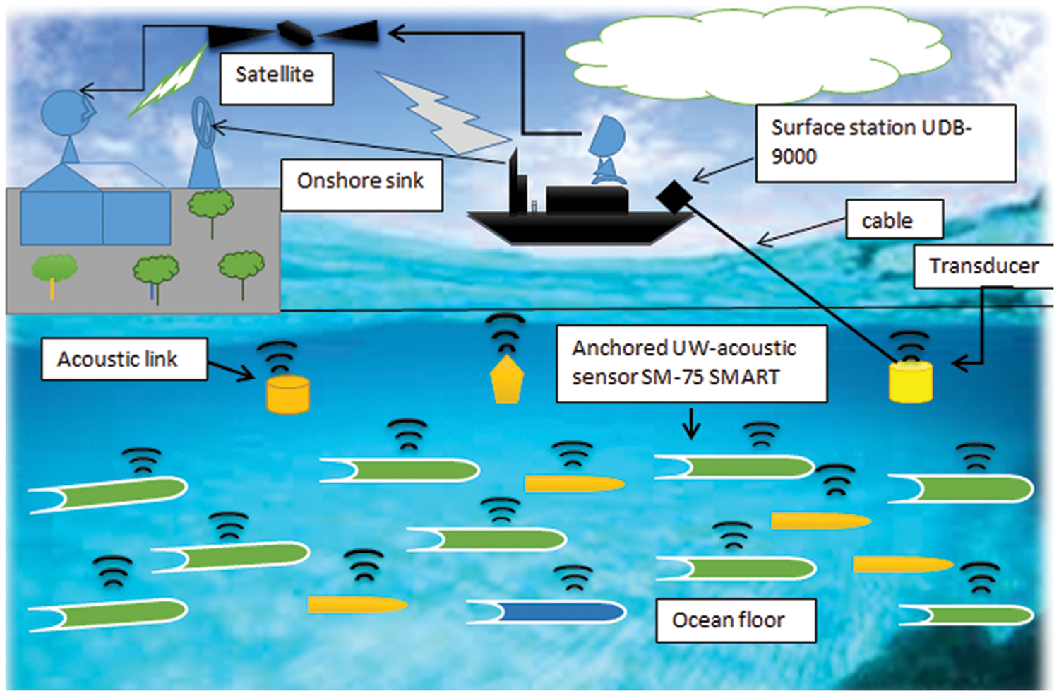
Figure 1: Proposed Model of CEER
Our proposed model contains a total of 225 randomly deployed nodes, which is a significant number. It consists of three tiers and nine clusters, each with three cluster heads (CH) and a total of three cluster heads (CH). Ten receivers are deployed on the water, and one base station is located on the shoreline. Throughout the layer, all CHs (layer 3) collect data from sensors and transmit it to CHs (layer 1) in the layer above. The CHs in layer 1 are in charge of data transmission to the receivers deployed on the water’s surface. These receivers aggregate, assemble and compile the data they receive before transmitting it to the base station.
The initial step was to configure the system. The network was randomly divided into three layers, layer 3, layer 2, and layer 1, with each layer further subdivided into three clusters, as illustrated in Fig. 2. The next step was to select CHs within each cluster using the formula. For weight function criteria with three possible states, selection (yes), next phase (routing phase), and rejection state transitions are all possible (no). The next step was to choose a weight function criterion for CH in each of the three layers using three state transitions: (1) selection (yes), (2) next stage (routing), and (3) rejection state. The process is depicted in the following figure (2).
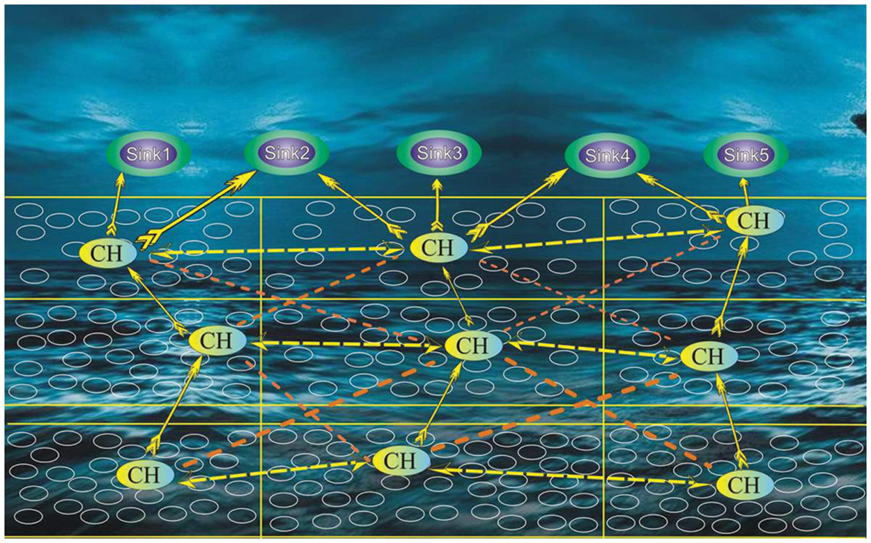
Figure 2: Cooperative Energy Efficient Routing (CEER) Cluster-based Protocol
Additionally, when the condition was met, the routing phase was initiated, and the optimal path was chosen from a list of possible paths. The path was chosen based on two criteria: first, if the source’s Residual Energy (RE) is greater than the CH, the node forwards the data directly to the receiver; and second, if the source’s RE is less than the CH, the node forwards the data indirectly to the receiver. Following that is the CH strategy. When any of the sink conditions are met, the following CH strategy is used, which consists of three CH A, B, and C groups. The sink is determined by the CH group selected for data forwarding. If receivers 1 and 2 are members of the group, data is forwarded to them; if they are not, data is forwarded to receivers 3 and 4. Regarding receivers 5.
The design of the CEER protocol for UWSNs was proposed using a mathematical formulation. A routing protocol called the CEER protocol had been developed for UWSNs. Nodes were deployed underwater in three layers using a clustering and collaboration mechanism, with nine clusters totaling 225 nodes. five receiver sinks were deployed on the ocean’s surface, and each cluster has its own base station. Each CH is responsible for data collection from nodes. The CHs transmit the data to the receivers. The receiver aggregates the data and transmits it to the base station for further processing.
Three distinct functions are performed during the initialization phase, which is the start of the process. Each node is informed during this phase, check the presence and location of nearby nodes and the location of sink nodes implanted in the water. All possible routes to countless sinks are thoroughly checked and analyzed. The sensors communicate their depth readings to nearby nodes and receivers. Each node sends packets containing information such as node ID, energy status, and depth. The receiver communicates with them to obtain information about each node via hello packets. Each node uses a hello packet broadcast to identify nearby nodes within the transmission range and to keep the isolation line between nearby nodes below the depth threshold to quantify and identify the pure and optimal transmission transponder nodes for data transmission.
In the Cluster-Head-Selection phase, each node calculates its weight. After calculating weight, each node broadcasts its weight to other nodes. The node with the highest Wg value is selected as the CH node. Each node calculates its weight (Wg) using the mathematical model given in Eqs. (1)–(3).
PL = path loss, Si = source, Ri = relay, Di = destination, SNR = signal to noise ratio
where PL is the path loss of the corresponding co-links from to i and from i to i, and SNR (Si, Ri) and SNR (Ri, Di) are the SNR adjustment of the nodes running from Si to i and the form, respectively Si connected to i. Renewable energy is the remaining energy from consecutive decades.
The resulting two-stage transmission method enables transmission from relay and transmitting nodes without overlapping. In the second stage, the entire cooperation system will be relocated. In the first stage, the Si node of the source node relays its useful information to both the relay node R and the destination node D. In contrast, in the second stage, the relay node R sends the received information to D. d1 and the l time interval between target and relay is d2. This type of information comes from the first stage transmit node received from D and R and can be represented by Eqs. (4) and (5).
In Eqs. (4) and (5), y_SiRi is the transmission information from source to relay, and y_SiDi is the transmission information from source to destination. In this case, the term 〖P〗 _1 denotes the strength of the signal transmitted by the transmitter. xSi is the symbol for relaying information from one of the transmitters of ii Si, h_ (Si, Ri), and h_SiDi are the properties of the radio communication medium from S_i to R_i and from S_i to D_i. The coefficients of these expressions are generated and modeled as a complex Gaussian random variable (GRV) with mean 0 and variance σ2, called CN (0, σ2). The channel variance is shown in Eq. (6).
where the interval between two nodes is i and which is the propagation of the signal loss factor and a constant whose value depends on the propagation of the signal state. N_(Si, Ri) and N_SiDi are the noise characteristics given by S_i to Ri and Si to D respectively in a given connection and are related to the characteristics mentioned in the second stage, i.e., H. The relay picks up the symbol power amplified with the power P2 and sends it to the target in a targeted manner.
The signal y_RiDi received in the second stage at the destination is shown in Eq. (7). In this case, p_2^’ = p_2 means that if the relay receives the transmitted symbols efficiently/fast, otherwise p_2^’ = 0, x si is what after the communication from S to R (source to relay) the signal in Regarding the destination node, the signal returns the full and comprehensive power P of the transmitted signal in the form of P1 + P2 = P.
3.2.4 Relay Selection and Routing Phase
The sender node Source I has a total of n nearby nodes within its transmission range during this phase. Irrespective of the network’s size, it depends entirely on the nodes’ priority order to determine which node controls the clustering mechanism efficiently and reliably and selects that node as a cluster among the others.
Every 50 s sink nodes send packets with a hello message to the rest of the network in order to determine the number of dead nodes. It is utilized, and the development area is distinguished from the network’s alternate state, as well as some network parameters calculated in this case. If a subsequent target destination is successfully reached, feedback is broadcast in the form of an acknowledgment to other nearby sender nodes. This eliminates the requirement for additional transmissions via any nearby nodes. The sender node transmits messages to the relay node, which performs the identification process. Node contact is maintained and the packet from the sender node is transmitted to a sink node, which is implanted in the water without being detected by the relay node. When there are multiple relay nodes on the route and the sending node is composed of a sink node with its upcoming hops, it is not the responsibility of the relay node to initiate or generate a collaborative process. This procedure contributes to a decrease in the amount of residual energy remaining after the information is transmitted. Eqs. (8) and (9) can be used to demonstrate this technique.
The relay strategy takes into account the AF (Amplification and Forward) method of the node acting as the Ri relay, and the acknowledgment signal from S_i from the start of transmission to the destination D_i is multiplied by the gain factor G, i.e., H. Y_rd = G(Y_sr). This scheme assumes that the consumption of the relay is equal to the power consumed by the sending node during the first hop. In the presence of a CSI burst on R (CSI secondary relay), the amplifier parameter G can be expressed by Eqs. (10) and (11).
where
The notation
Each target/target node D includes a hybrid binding method to collect recognition signals from Si and Ri. The MRC method used here is a combinatorial strategy. The endpoint or destination improves efficiency by combining the signals from two transmission hops using the MRC (Maximum Ratio Merging) method. Mathematical interpretation of Eq. (12).
In Eq. (12),
3.3 Performance Evaluation Metrics
The metrics chosen to evaluate performance are total latency, power efficiency, packet delivery speed, and network stability.
End-to-end latency is the time it takes for a packet to travel from the sender to the receiver over the connection. It is a common term when monitoring IP connections. The latency depends on the number of hops and the congestion of the network.
The term energy efficiency refers to the energy quality of the node when communicating via CCEER. For example, when a sensor node sends information from source to destination, it consumes less energy and stays longer, which is called energy efficiency.
3.3.3 Packet Delivery Ratio (PDR)
It is the ratio between the number of packets sent by the source node and the number of packets seen by the receiving node. The whole number of packets is effectively acknowledged at the sink, which is named packet delivery ratio or throughput.
3.3.4 Network Stability Period
The network stability period is defined as “the time interval from the start of the network to the death of the first node that indicates how stable the network is.” The total time interval from when a node starts communicating with other nodes until the death event occurs. In other words, when a node’s total power is completely consumed, causing that node to stop communicating with another node. Stability is measured in laps or seconds. The simulation parameters are shown in Table 1.
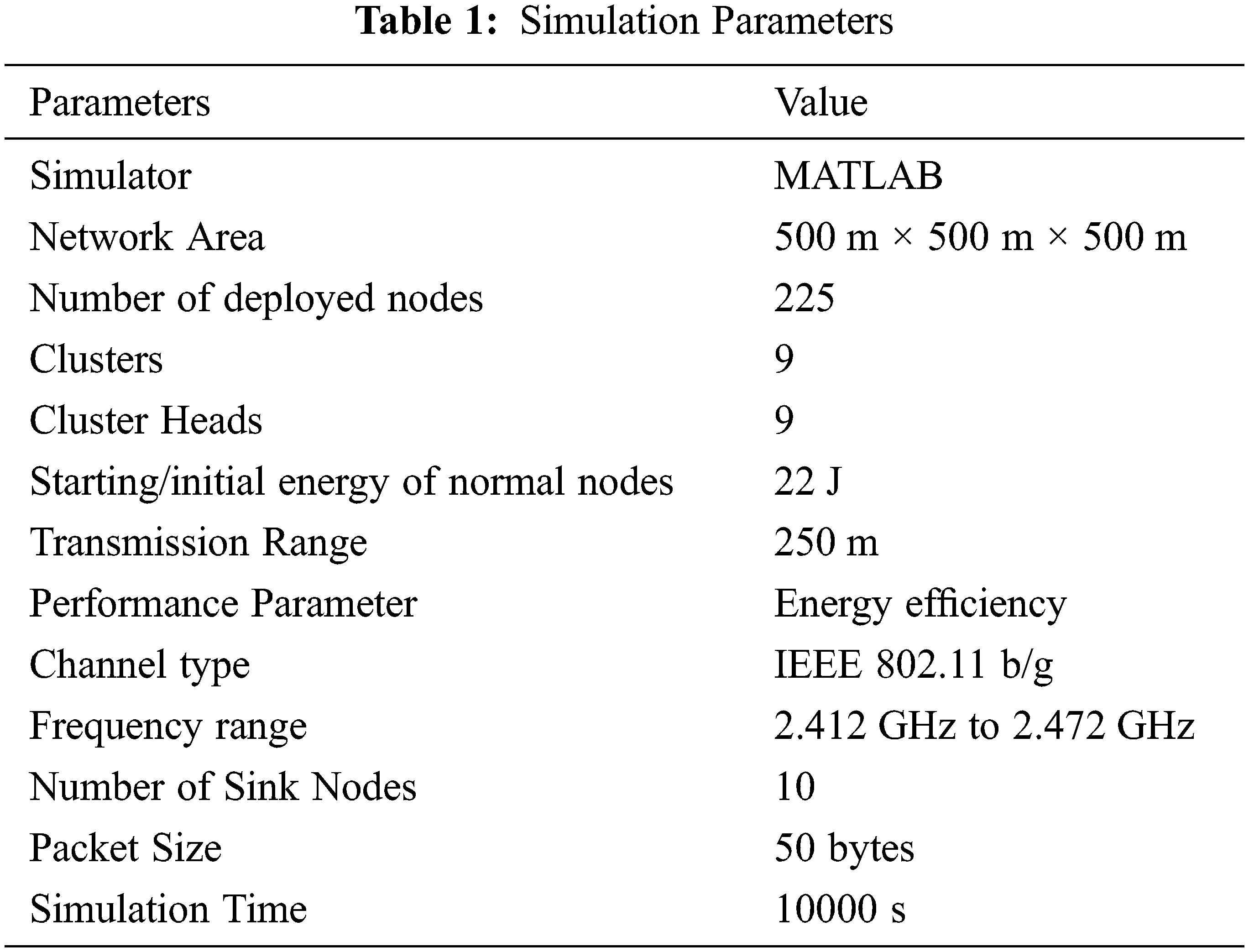
This chapter analyses actual simulations and their generated results for various parameters, including E2ED, total energy consumption, PDR, and network stabilization period. To assess and analyze CEER’s efficiency and performance, it is compared to the existing Co-UWSN and Low Energy Adaptive Clustering Hierarchy (LEACH) schemes implemented in the United Kingdom. Ten tanks are embedded in the water’s surface, and 225 nodes are discrete and unclassified within a 500 m × 500 m × 500 m network field. The tanks are connected via a 500 m × 500 m network field. Each node broadcasts a set of dynamic physical metrics along with its data. This scheme’s overall performance is compared to the existing Co-UWSN and LEACH schemes. Each simulation technique’s nodes were randomly assigned to nodes in the 10000 simulation rounds. Ten sinks were placed at the water’s surface, and 225 nodes were randomly placed across a 500 m × 500 m × 500 m field of the network to collect data. Each round, all living nodes transmit data to the receiver based on thresholds, which the receiver receives. Each node communicates with its neighbors about critical physical metrics such as depth thresholds and weights to keep them updated on changes in the network environment. Nodes calculate their distance from adjacent nodes once every 100 rounds. Data is transmitted from the source node to the upper layer via neighboring nodes until it reaches the receiver. Receiver nodes monitor the collaboration nodes’ depth thresholds and adaptive mobility due to the inclusion of collaboration, cooperative diversity, and depth threshold variation in this scheme.
E2ED with the various approaches is represented in Fig. 3 shows the comparison-based study between E2ED of CCEER, Co-UWSN, and LEACH. The results obtained from the comparison of simulation have shown that E2ED in CCEER is fewer/less than Co-UWSN and LEACH because of the lowest distance between the nodes in poor and impenetrable situations. CCEER has a lower end-to-end delay than the other protocols due to the minimum propagation distance between nodes under dense and sparse conditions. The delay is much higher with Co-UWSN and LEACH in the final rounds due to the long data transmission distance. After 4000 rounds, the network is considered stable as the sparsity of the network gradually increases, and the network forces data to be forwarded at the shortest possible distance. The simulation was carried out for 10,000 s; the results were plotted in Fig. 3. In CCEER, the E2ED after 5000 rounds is 56.41 compared to Co-UWSN, which is 70.11, and LEACH is 71.33. The decrease in the delay is due to the clustering and cooperation technique on the CH level. The x-axis shows the time in a sec, and the y-axis indicates the E2ED in seconds.
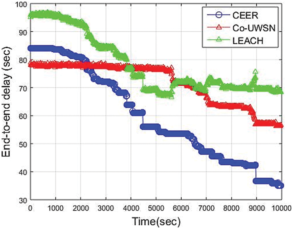
Figure 3: End-to-End Delay vs. Time (Sec)
Fig. 4 illustrates the Total Energy Consumption of CCEER compared to other energy-efficient schemes. In CCEER, energy utilization of sensor nodes is much more efficient because cooperation improves the data forwarding with the help of neighbor nodes, and load balancing is achieved. Due to energy efficiency and collaboration with neighboring nodes, CCEER can optimize data forwarding and load balancing, resulting in more efficient energy consumption by CCEER system sensors. Additionally, efficient weight implementation and lighter data transmission contribute to energy savings. By focusing on time-critical application requirements and leveraging collaboration and depth differences between data forwarders, LEACH and Co-UWSN could address their higher energy consumption than other techniques. As a result, the likelihood of cooperative routing occurring at any source node is decreased, resulting in decreased energy consumption. Results in Fig. 4 show that energy consumption in CCEER is less than Co-UWSN and LEACH due to the regular selection of high-energy nodes. The simulation was run for 10,000 s. For the first 4000 sec, the energy consumption of CCEER is 14.15 joule compared to 15.01 joule of Co-UWSN and 15.07 joule of LEACH. The simulation proved that CCEER consumes less energy as compared to Co-UWSN and LEACH.
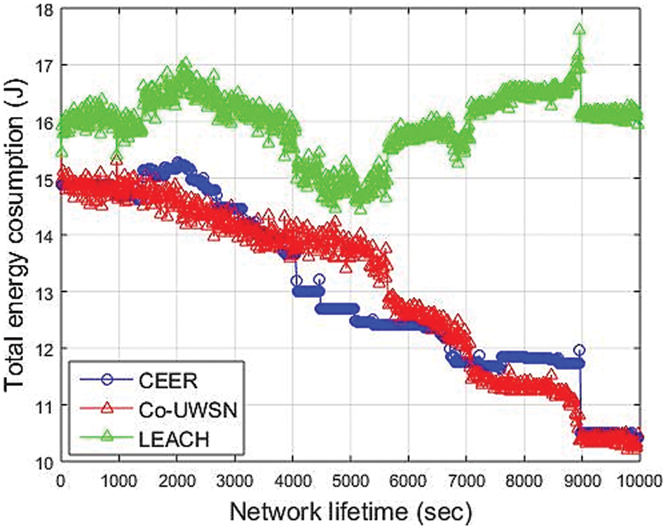
Figure 4: Total Energy Consumption vs. Time (Sec)
As Fig. 5, CCER has a significantly higher packet delivery ratio (PDR) than the other protocols mentioned above. The performance of Co-UWSN and LEACH degrades, whereas the delivery ratio of Co-UWSN shows a similar curve pattern, even though the degradation of PDR in CEER is significantly less than the degradation of Co-UWSN and LEACH. When the time interval between packets is small, the amount of traffic sent from the source node is greater. This result is an increase in packet conflicts and a decrease in packet delivery ratio. It increases the probability of packet reception success by forwarding packets on multiple paths and merging them at the receiving node, as the CEER scheme specifies. Fig. 5 illustrates that the presence of additional cooperating nodes enables data forwarding. As a result, increased reliability is possible. Because Co-UWSN and LEACH employ long-distance propagation in addition to multiple forwarding, they have a higher loss than the CEER technique, which has a lower PDR, but a higher loss. In Fig. 5, the x-axis show time in the second, and Y-axis show PDR. The simulation runs for 10,000 s; after 4000 sec, the PDR for CEER is 90.01, Co-UWSN is 80.0 and for LEACH is 60.01. The simulation result shows that the Packet Delivery Ratio of CEER is better than other protocols.
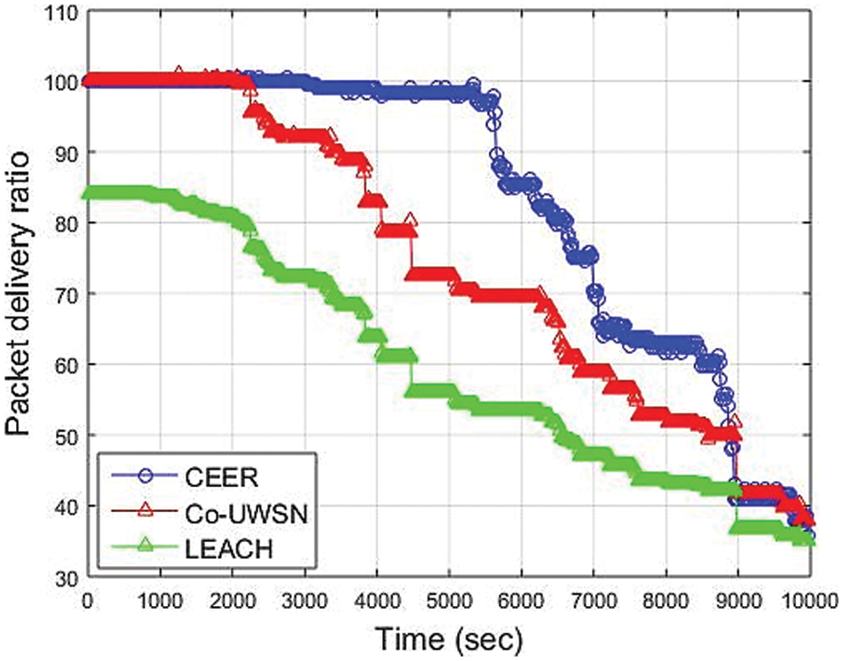
Figure 5: Packet Delivery Ratio vs. Time (Sec)
Furthermore, as illustrated in Fig. 6, the path loss of the network is significantly greater in Co-UWSN and LEACH than in CEER, owing to the emphasis placed on SNR in their network modeling. The CH node is more effective and preferred than other schemes in CEER, where Urick and Thorp’s UWA fading models are used to track and measure the total transmission loss between sources during data transfer. It considers the transmission frequency, bandwidth efficiency, and the effect of noise when determining the signal quality during data forwarding. However, unlike CEER, it does not account for noise or transmission loss, which results in significantly lower performance when compared to CEER. Because Co-UWSN and LEACH have a high network density, there are fewer losses during the initial node deployment phase. As a network becomes more decentralized, its losses increase, resulting in decreased network performance and, eventually, high packet loss during data transmission.
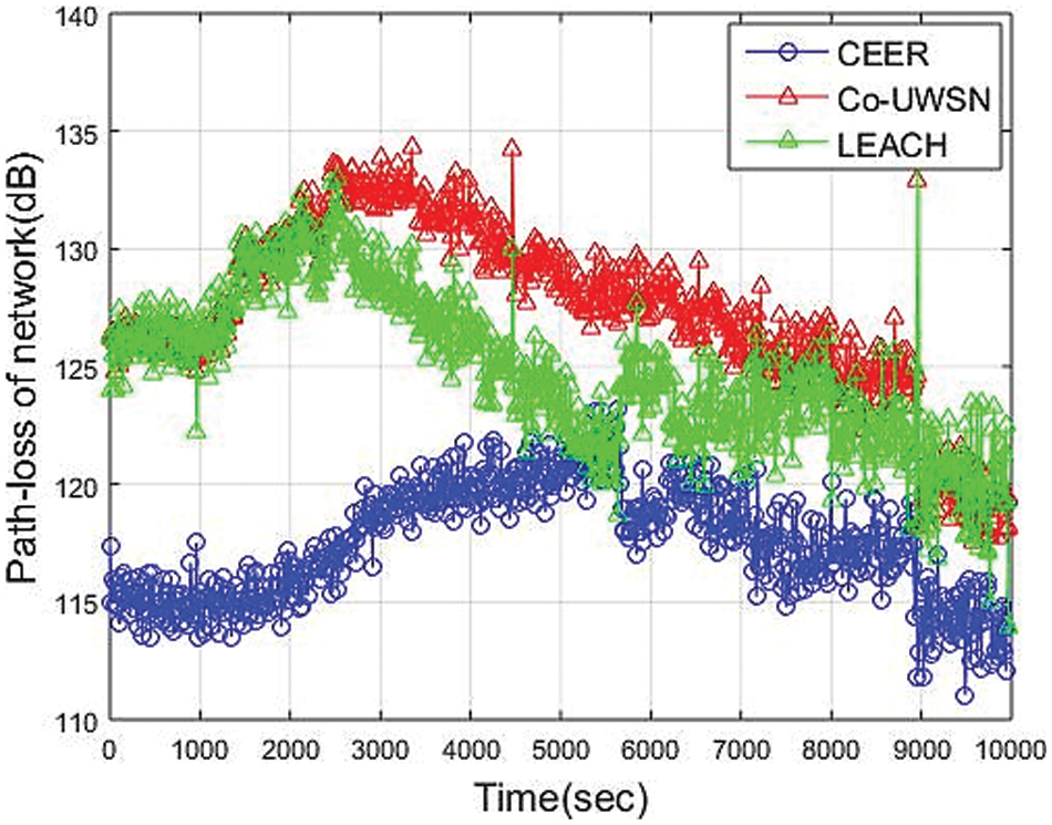
Figure 6: The Path Loss vs. Time (Sec)
Similarly, the protocol in terms of equal posterior path loss, SPARCO, outperforms other schemes in terms of SNR because it considers both the depth and residual energy at relay nodes and the collaboration scheme’s use. As a result, the protocol achieves a more stable interval of propagation traversal than SPARCO in terms of equal posterior path loss. As shown in the following figure, our CEER scheme is the most efficient in terms of path loss when compared to other schemes. The simulation runs for 10,000 s; after 4000 sec, the PL for CEER is 122 dB, Co-UWSN is 132.5 dB and for LEACH is 125.01 dB. The simulation result shows that the Path Loss of CEER is less than other protocols.
In Fig. 7, the CCER scheme extends the network’s stability period by avoiding redundant and unnecessary data transmission while minimizing transmission loss. In 10000-seconds of simulation, the first node in the Co-UWSN dies in 751 sec, in LEACH dies in 1100 sec, and our scheme, CEER, dies in 1150 sec, extending the period of stability. At the start, LEACH performs better when the first node dies, and then nodes die regularly. In simple words, it can be expressed that the period of instability initiates from nearly 751 s. The cooperation scheme among the nodes creates a load balancing problem in Co-UWSN, LEACH, and CCEER. By the time of network with unstable period slowly becomes a thin creating problem of load on high residual remaining energy nodes. The average number of alive nodes in CEER is 185, Co-UWSN is 165, and LEACH is 120. The more numbers of alive nodes show that CEER performs better in terms of Alive nodes. The x-axis expresses the time in seconds, while the y-axis expresses the number of alive nodes. The CEER, Co-UWSN, and LEACH networks collaborate to achieve load balancing.
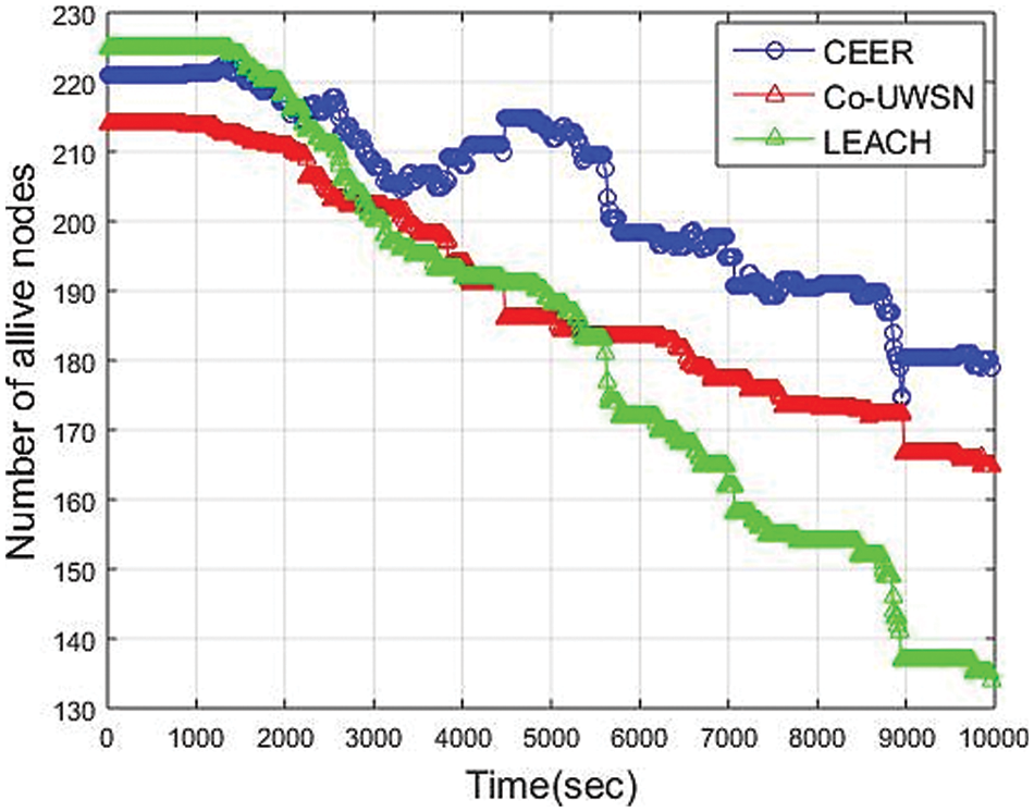
Figure 7: Alive nodes vs. network Lifetime (Sec)
• Comparison of CCEER with Co-UWSN and LEACH: This section presented the design of CCEER, inspired by the design of Co-UWSN. The Co-UWSN protocol must adhere to the data routing and collaboration principle of data routing with cooperation. Cooperation is important in improving routing schemes for UWSNs and LEACH. Co-UWSN and LEACH have cooperation but not a clustering mechanism. In the design of CCEER, the focus was on clustering with cooperation. Finally, the proposed protocol was compared with the existing Co-UWSN and LEACH routing protocol in UWSNs, and the scheme showed more promising results than existing schemes. In addition, CCEER is more energy efficient compared to Co-UWSN and LEACH.
In this research, the CCEER routing scheme is suggested to increase the network’s lifetime and minimize the energy consumption of UWSNs. Using a cooperation and clustering mechanism increases the network’s lifetime, maximizes PDR, E2ED, consumption of total energy, stability period, and path-loss, which minimizes the entire energy consumption of the network. This is particularly significant and useful for time-critical and delay-sensitive kinds of applications. The scheme of transmission without cooperation is based on the estimation of the channel, which enhances the quality of the received packets at the destination node but doing communication with a single path may cause a problem in which the route/path might be affected when the quality of the channel changes. The selection of the CH scheme concludes the sudden conditions of the link and the range among the nearby CHs to forward the data packets to other CHs efficiently. Sink and BS as the final destination. Alternation’s in-depth threshold enhances the number of applicable CHs, therefore reducing some crucial data loss in delay-sensitive uses. Features of the single and multi-hop transmission approaches have been used to minimize collision, and path loss can affect and maximize the network’s lifetime. Optimum weight computing and character of cooperation not only offer the balancing of the load within the network along with the capacity enhancement in the stability period of the network. It may be possible to develop a mathematical model in the future that will allow us to further reduce our energy consumption and have more secure in all terms. The UWSN data forwarding strategy is optimized using a variety of parameters, including depth, energy, data traffic, and the number of neighboring nodes. The limitations of UWSNs are as very expensive. Everyone cannot afford to install it. UWSNs cannot be used for faster communications. It is designed for low-speed applications. It is easy to hack by hackers.
This research work is focused on the significance of a cluster-based energy efficiency mechanism in the routing protocols for the UWSNs environment. The produced results showed that the proposed solution is still suitable for the UWSNs environment. In addition, the proposed solution will encourage the research community to design other energy-efficient solutions for UWSNs as well as other environments. Many possible research directions in this area can be designed using artificial intelligence models for energy efficiency in UWSNs environment. In future work, we have a plan to introduce other energy efficient solutions for different environments.
Funding Statement: This work was supported by the National Research Foundation of Korea-Grant funded by the Korean Government (MSIT)-NRF-2020R1A2B5B02002478). This research work was also supported by the Cluster grant R20143 of Zayed University, UAE.
Conflicts of Interest: The authors declare that they have no conflicts of interest to report regarding the present study.
References
1. T. Hussain, Z. U. Rehman, A. Iqbal, K. Saeed and I. Ali, “Two hop verification for avoiding void hole in underwater wireless sensor network using SM-AHH-VBF and AVH-AHH-VBF routing protocols,” Transactions on Emerging Telecommunications Technologies, vol. 31, pp. 3992, 2020. [Google Scholar]
2. Z. Ur Rehman, A. Iqbal, B. Yang and T. Hussain, “Void hole avoidance based on sink mobility and adaptive two hop vector-based forwarding in underwater wireless sensor networks,” Wireless Personal Communications, vol. 120, pp. 1417–1447, 2021. [Google Scholar]
3. A. Hussain, H. U. Khan, S. Nazir, I. Ullah and T. Hussain, “Taking FANET to next level: The contrast evaluation of moth-and-ant with Bee Ad-hoc routing protocols for flying Ad-hoc networks,” ADCAIJ: Advances in Distributed Computing and Artificial Intelligence Journal, vol. 10, pp. 321–337, 2021. [Google Scholar]
4. J. Shen, H. -W. Tan, J. Wang, J. -W. Wang and S. -Y. Lee, “A novel routing protocol providing good transmission reliability in underwater sensor networks,” Journal of Internet Technology, vol. 16, pp. 171–178, 2015. [Google Scholar]
5. R. W. Coutinho, A. Boukerche, L. F. Vieira and A. A. Loureiro, “Design guidelines for opportunistic routing in underwater networks,” IEEE Communications Magazine, vol. 54, pp. 40–48, 2016. [Google Scholar]
6. W. Kun, T. Yuzhen and S. Yinhua, “Energy balanced pressure routing protocol for underwater sensor networks,” in 2016 Int. Computer Symp. (ICS), Taiwan, pp. 216–220, 2016. [Google Scholar]
7. A. Nayyar, V. Puri and D. -N. Le, “Comprehensive analysis of routing protocols surrounding underwater sensor networks (UWSNs),” in Data Management, Analytics and Innovation, ed: Singapore: Springer, pp. 435–450, 2019. [Google Scholar]
8. A. Nayyar and V. E. Balas, “Analysis of simulation tools for underwater sensor networks (UWSNs),” in Int. Conf. on Innovative Computing and Communications, Singapore, pp. 165–180, 2019. [Google Scholar]
9. Z. Wang, G. Han, H. Qin, S. Zhang and Y. Sui, “An energy-aware and void-avoidable routing protocol for underwater sensor networks,” IEEE Access, vol. 6, pp. 7792–7801, 2018. [Google Scholar]
10. G. Tuna and V. C. Gungor, “A survey on deployment techniques, localization algorithms, and research challenges for underwater acoustic sensor networks,” International Journal of Communication Systems, vol. 30, pp. e3350, 2017. [Google Scholar]
11. A. Khan, I. Ali, A. U. Rahman, M. Imran and H. Mahmood, “Co-EEORS: Cooperative energy efficient optimal relay selection protocol for underwater wireless sensor networks,” IEEE Access, vol. 6, pp. 28777–28789, 2018. [Google Scholar]
12. M. Khalid, Z. Ullah, N. Ahmad, H. Khan, H. S. Cruickshank et al., “A comparative simulation based analysis of location based routing protocols in underwater wireless sensor networks,” in 2017 2nd Workshop on Recent Trends in Telecommunications Research (RTTR), New Zealand, pp. 1–5, 2017. [Google Scholar]
13. M. Khalid, Z. Ullah, N. Ahmad, A. Adnan, W. Khalid et al., “Comparison of localization free routing protocols in underwater wireless sensor networks,” International Journal of Advanced Computer Science and Applications, vol. 8, pp. 408–414, 2017. [Google Scholar]
14. X. Du, M. Li and K. Li, “Reliable Transmission Protocol for Underwater Acoustic Networks,” in Computer and Network Security Essentials, ed: Cham: Springer, pp. 173–187, 2018. [Google Scholar]
15. F. Ahmed, Z. Wadud, N. Javaid, N. Alrajeh, M. S. Alabed et al., “Mobile sinks assisted geographic and opportunistic routing based interference avoidance for underwater wireless sensor network,” Sensors, vol. 18, pp. 1062, 2018. [Google Scholar]
16. N. Javaid, Z. Ahmad, A. Sher, Z. Wadud, Z. A. Khan et al., “Fair energy management with void hole avoidance in intelligent heterogeneous underwater WSNs,” Journal of Ambient Intelligence and Humanized Computing, vol. 10, pp. 4225–4241, 2019. [Google Scholar]
17. P. Gjanci, C. Petrioli, S. Basagni, C. A. Phillips, L. Bölöni et al., “Path finding for maximum value of information in multi-modal underwater wireless sensor networks,” IEEE Transactions on Mobile Computing, vol. 17, pp. 404–418, 2017. [Google Scholar]
18. A. Hussain, B. Shah, T. Hussain, F. Ali and D. Kwak, “Co-DLSA: Cooperative delay and link stability aware with relay strategy routing protocol for flying Ad-hoc network,” Human-centric Computing and Information Sciences, vol. 12, pp. 1–21, 2022. [Google Scholar]
19. S. Jabbar, M. Asif Habib, A. A. Minhas, M. Ahmad, R. Ashraf et al., “Analysis of factors affecting energy aware routing in wireless sensor network,” Wireless Communications and Mobile Computing, vol. 2018, pp. 1–22, 2018. [Google Scholar]
20. Q. Liu, X. Chen, X. Liu and N. Linge, “CACA-UAN: A context-aware communication approach to efficient and reliable underwater acoustic sensor networks,” International Journal of Sensor Networks, vol. 26, pp. 1–11, 2018. [Google Scholar]
21. Y. Zhang, J. Liang, S. Jiang and W. Chen, “A localization method for underwater wireless sensor networks based on mobility prediction and particle swarm optimization algorithms,” Sensors, vol. 16, pp. 212, 2016. [Google Scholar]
22. A. Prasanth, “Certain investigations on energy-efficient fault detection and recovery management in underwater wireless sensor networks,” Journal of Circuits, Systems and Computers, vol. 30, pp. 2150137, 2021. [Google Scholar]
23. K. K. Gola and B. Gupta, “Underwater acoustic sensor networks: An energy efficient and void avoidance routing based on grey wolf optimization algorithm,” Arabian Journal for Science and Engineering, vol. 46, pp. 3939–3954, 2021. [Google Scholar]
24. K. Saeed, W. Khalil, S. Ahmed, I. Ahmad and M. N. K. Khattak, “SEECR: Secure energy efficient and cooperative routing protocol for underwater wireless sensor networks,” IEEE Access, vol. 8, pp. 107419–107433, 2020. [Google Scholar]
25. K. Latif, N. Javaid, I. Ullah, Z. Kaleem, Z. Abbas Malik et al., “DIEER: Delay-intolerant energy-efficient routing with sink mobility in underwater wireless sensor networks,” Sensors, vol. 20, pp. 3467, 2020. [Google Scholar]
26. K. Bhattacharjya, S. Alam and D. De, “CUWSN: Energy efficient routing protocol selection for cluster based underwater wireless sensor network,” Microsystem Technologies, vol. 28, pp. 543–559, 2022. [Google Scholar]
27. F. Banaeizadeh and A. Toroghi Haghighat, “An energy-efficient data gathering scheme in underwater wireless sensor networks using a mobile sink,” International Journal of Information Technology, vol. 12, pp. 513–522, 2020. [Google Scholar]
28. B. Venkateswarulu, N. Subbu and S. Ramamurthy, “An efficient routing protocol based on polar tracing function for underwater wireless sensor networks for mobility health monitoring system application,” Journal of Medical Systems, vol. 43, pp. 1–8, 2019. [Google Scholar]
Cite This Article
 Copyright © 2023 The Author(s). Published by Tech Science Press.
This work is licensed under a Creative Commons Attribution 4.0 International License , which permits unrestricted use, distribution, and reproduction in any medium, provided the original work is properly cited.
 Downloads
 Citation Tools