
 Submit a Paper
 Propose a Special lssue
 Open Access
REVIEW
Review on Capacity Optimization of Traction Transformer for High-Speed Railway
1 School of Automation and Electrical Engineering, Lanzhou Jiaotong University, Lanzhou, 730070, China
2 School of New Energy and Power Engineering, Lanzhou Jiaotong University, Lanzhou, 730070, China
* Corresponding Author: Ruoqiong Li. Email:
(This article belongs to the Special Issue: Advances in Modern Electric Power and Energy Systems)
Energy Engineering 2022, 119(6), 2533-2548. https://doi.org/10.32604/ee.2022.020803
Received 16 December 2021; Accepted 08 April 2022; Issue published 14 September 2022
 View Full Text
 Download PDF
Abstract
In electrified railways, traction load not only fluctuates between peaks and valleys, but also has a situation of low utilization rate of average load throughout the day and short overload. The traction transformer selects the capacity with the peak load as the demand boundary, which will cause the capacity utilization rate to be low and even lead to the economic decline of the traction power supply system. This article summarizes the existing configuration methods for capacity optimization of traction transformer. Then under the conditions of energy storage and new energy access to traction power supply system, the three aspects are described as follows. Firstly, the energy storage device is connected to the system, which can pull the capacity of traction transformer to achieve peak shifting and valley filling. Then, the possibility of integrated configuration of new energy and traction power supply system to optimize the capacity of traction transformer and the methods of optimal configuration of traction transformer capacity by using new energy such as wind and light are summarized. Finally, this paper discusses the current structure of new energy access to traction power supply system, and it looks forward to the feasibility of new energy access to traction power supply system cooperating with energy storage devices to optimize the capacity of traction transformer.Keywords
By the end of 2020, the operating mileage of high-speed railways in China has reached 37,900 km, accounting for 60% of the total mileage of high-speed railway in the world. The high cost of the high-speed railway often makes the railway department lose more and earn less, which increases the financial burden of the railway department, and the electricity cost accounts for the main part of the operation cost of the high-speed railway [1]. The traction substation is an essential part of the traction power supply system of the high-speed railway, and the energy consumption of traction accounts for as much as 2/3 of the energy consumption of the railway department. Therefore, taking effective measures to improve the high energy consumption of high-speed railways is an urgent problem to be solved under the trend of high-speed railway development in China.
Traction load is characterized by strong impact, fast-changing frequency, and large intermittent fluctuations between peaks and valleys. At the same time, because there is no operation data on traction load in China, the capacity design of the traction transformer can only meet the peak of traction load as the demand boundary. Since peak load is closely related to the capacity of the main transformer and maximum demand billing in the two-part tariff [2], if the capacity of the traction transformer is too large, additional costs will be paid. Peak load not only causes the main problems of power quality in negative sequence technically but also directly relates to the cost of electricity bills economically. The peak load duration of the traction power supply system of a high-speed railway is usually shorter during the actual operation, so the low utilization rate of transformer capacity is prone to occur, which leads to the economic decline of the traction power supply system [3–6]. Therefore, reducing the capacity of the main transformer in the traction power supply system can effectively solve the problem of high energy consumption in high-speed railways.
The measures of peak-shifting and valley-filling are commonly used in electric power systems to reduce the difference between peak and valley loads. The application of energy storage technology with peak-shifting and valley-filling effect and the access of new energy sources in traction power supply systemcan not only control negative sequence and reduce voltage unbalance [7], but can also create economic benefits in the implementation of the two-part electricity price system. In other words, it can achieve benefits that adopt the method of reducing the maximum requirement or reducing the installed capacity of the main transformer [8–10].
Nowadays, new energy technologies are mainly concentrated in non-traction areas in rail transit, such as providing lighting and communication functions for houses, stations and transformer substations along the line by using photovoltaic power generation system, but the traction power supply system of AC electrified railways with higher energy consumption is less used. Due to the high energy consumption of the traction power supply system, this paper summarizes the existing research on the optimal configuration method of the capacity of traction transformer, and it puts forward that new energy is connected to the traction power supply system and cooperates with the energy storage device to optimize the capacity of traction transformer. It is hoped to provide reference for the follow-up more in-depth research.
2 Capacity Optimization Method of Existing Traction Transformer
The traction load of high-speed railway exists as a situation which produced large fluctuation between peaks and valleys. At the same time, there is sometimes short-term overload. Therefore, the capacity of the traction transformer is generally designed according to the peak load, which will lead to the overall average load of the traction transformer being generally low. The optimization methods of traction transformer mainly include reducing the capacity of traction transformer through optimization algorithm and improving its capacity utilization by changing the wiring form of the main transformer.
2.1 Capacity Optimization of Traction Transformer Based on Algorithm
Because the traction load of the electrified railway has the characteristics of a large short-time load and small daily average load, the traction transformer is in an underload operation state most of the time, and there is a large surplus in capacity and operation life. Therefore, the capacity of the traction transformer can be improved through the optimization of the traction transformer capacity algorithm and a new control strategy to realize the safe and economic operation of the traction transformer. For example, document [11] optimizes the capacity algorithm of traction transformer, reduces the installation capacity of traction transformer and enterprise cost expenditure by increasing the overload multiple of traction transformer, and ensures the safe operation of the transformer after reducing capacity through the verification of “current limit, temperature limit, and life loss.” In [12], the Gaussian mixture model is used to cluster the measured data of traction substation, and then the neural network is introduced to match and classify the traction load.
According to the results of clustering classification, combined with probability density and the Monte Carlo sampling method, the traction load of the electrified railway is predicted. According to the heat transfer principle and relative aging calculation, the difference equation model of temperature rise and life loss of traction transformer in traction substation is established to optimize the capacity of traction transformer in new traction substation. In [13], the efficiency, insulation, heat dissipation, and stray parameters of transformers are taken into account. The transformer loss and leakage inductance are taken as optimization objectives. Taking transformer insulation requirements, core saturation and winding structure as constraints, the capacity of the traction transformer is optimized by the multi-objective optimization algorithm. According to the research on the relative life loss of transformers and the capacity of auxiliary equipment [14], the evaluation method of transformer load capacity under different load conditions is proposed. However, the optimization of its capacity is limited. So it is difficult to solve the problem of high energy consumption in high-speed railways by using only an algorithm to optimize the capacity of the traction transformer.
2.2 Capacity Optimization of Traction Transformer Based on Structure
Reducing the capacity level of traction transformers can save the operation costs of a traction substation, but if the method of replacing traction transformer is adopted, it will inevitably cause great waste, and this method can not meet the requirements of the long-term transportation capacity of a high-speed railway. According to the provisions on overload capacity of traction transformers, different connection modes of traction transformers have different overload multiples. Therefore, the capacity utilization of the transformer can be improved by optimizing the connection of the traction transformer. For high-speed railways, a large number of demonstrations have shown that pure single-phase connection, single-phase V connection, and three-phase V connection should be the preferred connection methods for traction transformers.
For example, in [15], based on the design structure of transformer, including core material, winding structure and leak-free design, an optimization equation with geometric variables is deduced, which reduces the design capacity of transformer. A solution based on a power flow controller is presented in [16]. The current distribution mechanism is analyzed, and the compensation control strategy is deduced. By balancing the power flow, the load of the motor train is optimally distributed across the power supply arms, and it is evenly distributed on the two windings of the traction transformer, which reduces its capacity requirements. At the same time, this method plays a significant role in improving power quality. However, with the improvement of the transportation capacity of high-speed railways [17], the installation capacity of traction transformers increases. When the pure single-phase connection traction transformer needs super-large installation capacity, it will inevitably produce serious negative sequence problems to the external power grid. So a solution is to transform the electrical phase separation, but electrical phase separation will restrict the development of high-speed railways [18].
3 Structure of Capacity Optimization of Traction Transformer with Energy Storage Device Connected
At present, the development of energy storage technology is relatively mature, and has been widely used in smart grids, renewable energy grid connections, and in the development of electric vehicles. The research and development of energy storage technology has attracted extensive attention worldwide. It can not only realize demand-side management, peak-shifting and valley-filling, and load smoothing, but it can also improve the working efficiency of power supply equipment [19]. What’s more, energy storage technology can reduce the cost of the power supply system [20,21], and it can improve the operation stability and reliability of the power supply system. In recent years, energy storage technology has been widely used and studied in rail transit. The structure of the traction power supply system with an energy storage device is divided into vehicle-mounted storage and stationary energy storage [1]. In this paper, the general structure of the traction power supply system connected with energy storage technology is analyzed, and it is found that the structure of the stationary energy storage is more conducive to the capacity optimization of the traction transformer [22–24].
3.1 Vehicle-Mounted Energy Storage
As shown in Fig. 1, when the train is under regenerative braking conditions, the train charges the energy storage device. On the other hand, when the train is in traction mode, the energy storage device discharges. The vehicle-mounted hybrid energy storage device is shown in Fig. 2, which connects the DC bus between the four-quadrant rectifier and PWM inverter. The power flow of the supercapacitor, accumulator and electric locomotive is realized by a bidirectional DC/DC converter and the regenerative braking energy is absorbed at different power levels. In [25], a vehicle-mounted hybrid energy storage system and its energy management method are presented. A high-capacity and high-power supercapacitor hybrid energy storage system with lithium titanate battery placed on an electric locomotive is designed. At the same time, the vehicle-mounted hybrid energy storage system can output regenerative energy to the vehicle to maintain the basic power demand under the emergency conditions such as permanent failure of regional catenary and power loss of substation [26]. To a certain extent, the shortcomings of large energy transmission loss, low power supply flexibility and difficulty in supplying power to electric locomotive under catenary failure of electrified railway ground energy storage system is solved [27], and the utilization efficiency of regenerative braking energy is also improved.
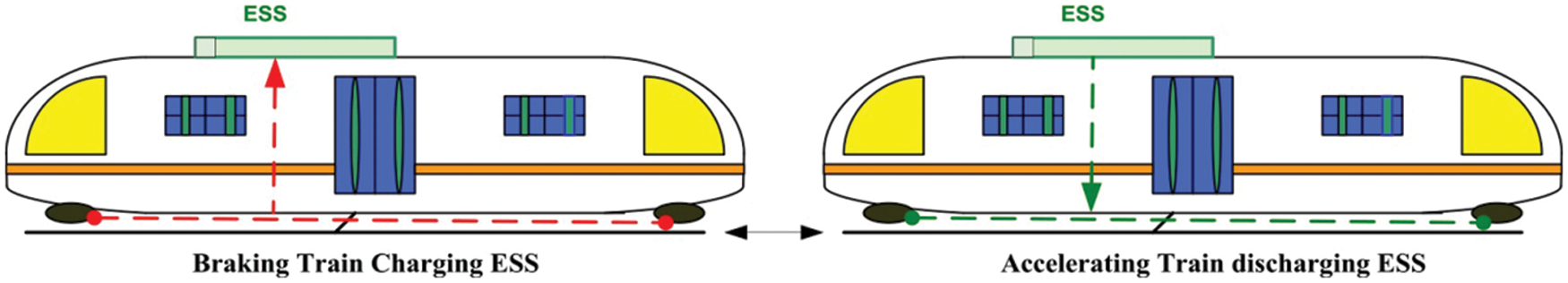
Figure 1: Vehicle-mounted energy storage
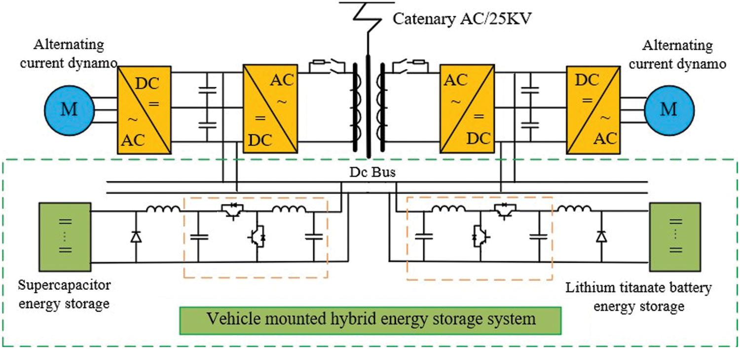
Figure 2: Vehicle-mounted hybrid energy storage structure
Although installing an optimal amount of energy storage units on electric locomotives can effectively store regenerative braking energy and release energy immediately when needed, vehicle-mounted energy storage requires modification of electric locomotives, which increases the weight and traction energy consumption of electric locomotives and increases their maintenance and operation costs. At the same time, for high-power regenerative braking energy, because the energy storage device needs a lot of space, the electric locomotive can not meet its requirements. The vehicle-mounted energy storage is not widely used at present.
The structure of stationary energy storage is shown in Fig. 3. The bidirectional AC/DC converter subsystem is connected to the 27.5 kV AC feeder through the step-down transformer, which forms a symmetrical back-to-back structure [28]. Its DC bus is connected to the energy storage device, which can maximize the use of regenerative braking energy and the energy stored in the energy storage device can be released at the peak load to share the pressure of the traction transformer. The purpose of reducing the capacity of the traction transformer is achieved. In [29], a new energy storage railway power regulator composed of the railway power regulator and supercapacitor is proposed. This system can not only realize the two-way energy flow between the two power supply arms, but also it can improve the utilization rate of regenerative braking energy and realize the function of peak shaving and valley filling through the coordinated control of railway power regulator and energy storage system.
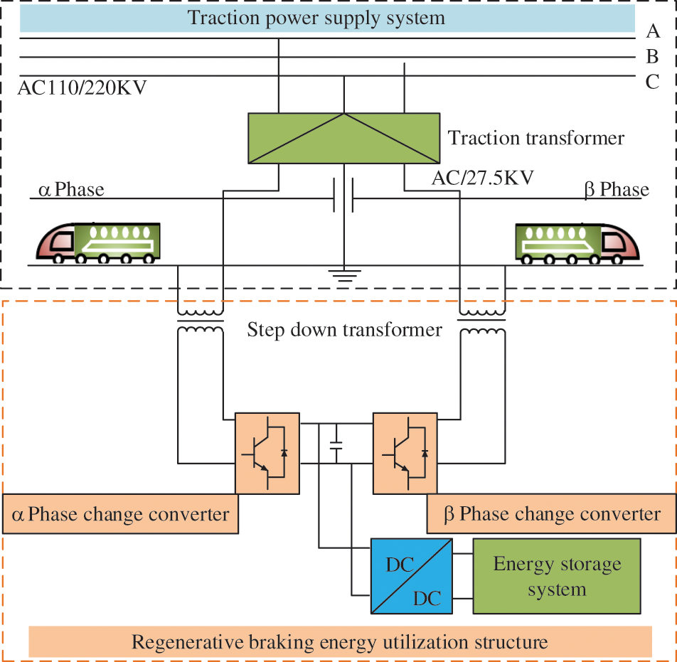
Figure 3: The structure of stationary energy storage
It can be seen from the above analysis that adopting the optimal feasibility scheme of stationary energy storage device can not only ensure that part of the regenerative braking energy is preferentially used by the traction locomotive, but also the power and capacity requirements of the energy storage unit is reduced [30]. The scheme can also reduce the installation capacity of traction transformer, the peak load power of a single power supply arm, and the maximum demand of substation, so it has the best comprehensive benefits. Because the railway power regulator is connected, RPC can realize the power flow between the two power supply arms, which reduces the load peak to a certain extent, and the utilization of the main transformer is improved [31]. Moreover, RPC can control negative sequences and dynamically compensate reactive power, which also has a certain effect on improving power quality [32]. Therefore, the selection of stationary energy storage based on supercapacitors is more conducive to the capacity optimization of traction transformers.
4 Integrated Configuration of New Energy and Traction Power Supply System
In recent years, in order to achieve the strategic goal of “energy conservation and emission reduction” and promote the high penetration and efficient utilization of new energy, scholars from home and abroad have actively explored and practiced new power supply modes such as multi-energy complementarity, microgrid, and energy Internet [33–35]. With the rapid development of China’s high-speed railway, new power supply modes such as multi-energy complementarity and microgrid can be considered to be applied to the electrified railway. Since the current new energy power generation system usually contains the DC part, a DC bus can be used as an energy transfer station, which can transmit electric energy to various electric equipment. As shown in Fig. 4, if the electric energy can be transmitted to the traction substation, the integrated configuration of new energy and traction power supply system can be realized, and the problem of low-capacity utilization of traction transformer can be solved, and the economy of the system can be improved. Therefore, a control strategy based on step energy management is proposed by some researchers, which improves the regenerative braking energy utilization rate of the system by suppressing the energy exchange between different energy storage media [36]. In [37], it is demonstrated that the rational use of energy can be achieved by setting appropriate thresholds and allocation ratios.
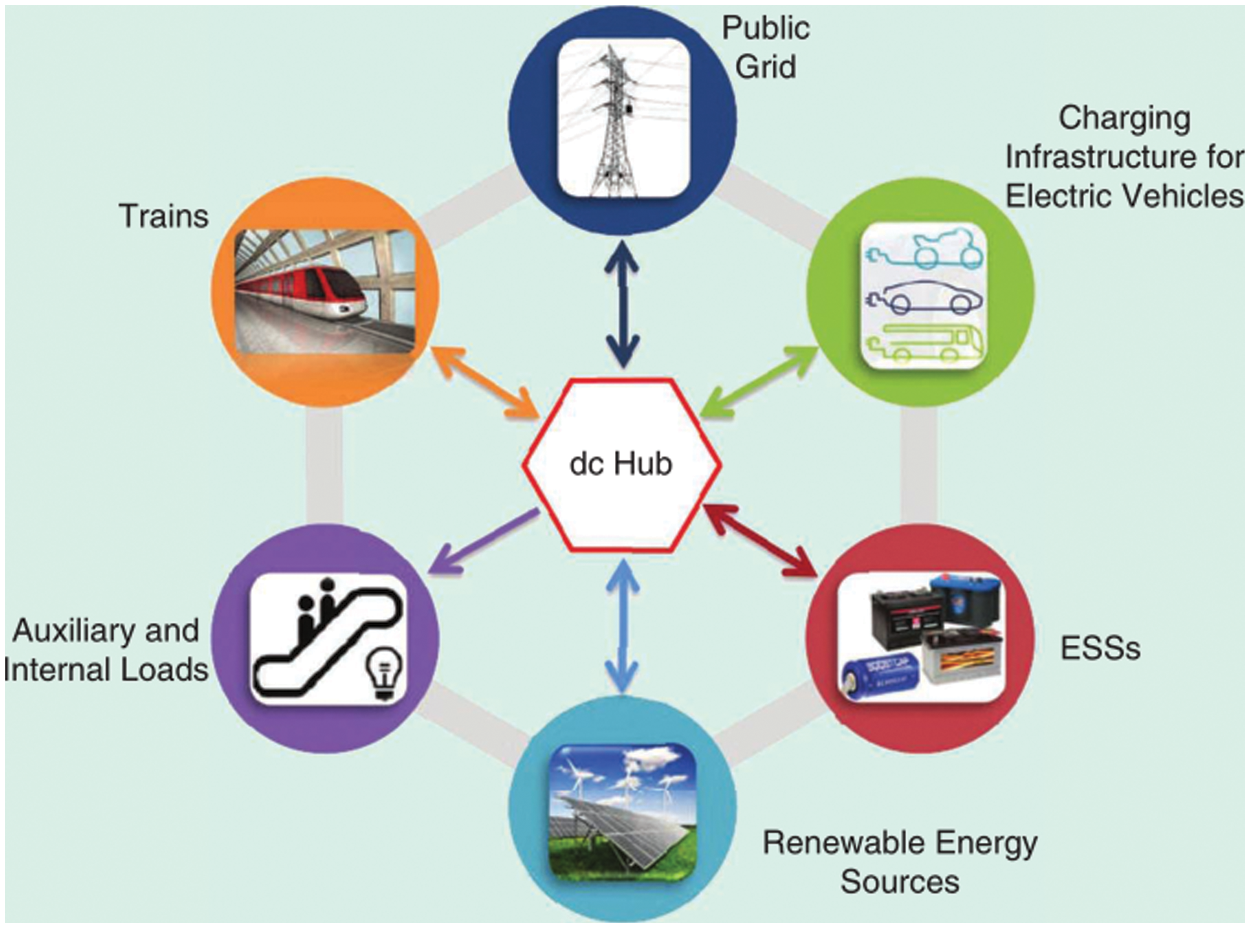
Figure 4: Energy interconnection structure
With the rapid development of new energy technology in China, the integrated configuration of new energy and traction power supply systems is an inevitable trend. The topological structure given in [38] is shown in Fig. 5. Since China’s railway network covers all parts of the country, on-site distributed energy is provided along the railway, which can realize the nearby consumption of energy. At the same time, the small-capacity on-site distributed energy does not need complex power conversion and long-distance transmission, which can balance local energy supply and demand. It also makes it possible to realize peak shifting and valley filling of traction substation load, but its wide distribution may not be convenient for railway department operation and maintenance. Furthermore, a single structure affected by the external environment may cause power quality problems. The integrated distributed energy structure is shown in Fig. 6. The integrated distributed energy is connected to the power grid with high-power electronic equipment, which can realize large-scale, long-distance transmission, so that it can supply power to the traction power supply system. If the integrated distributed energy needs to be connected to the AC power grid, a matching converter needs to be used to meet the same frequency, amplitude, and phase angle [39]. Compared with on-site distributed energy, this topology has longer transmission lines, a larger scale, convenient maintenance, and lower operation cost. However, this structure needs to establish a special distributed network, and its investment, payback period, and return on investments should be considered.
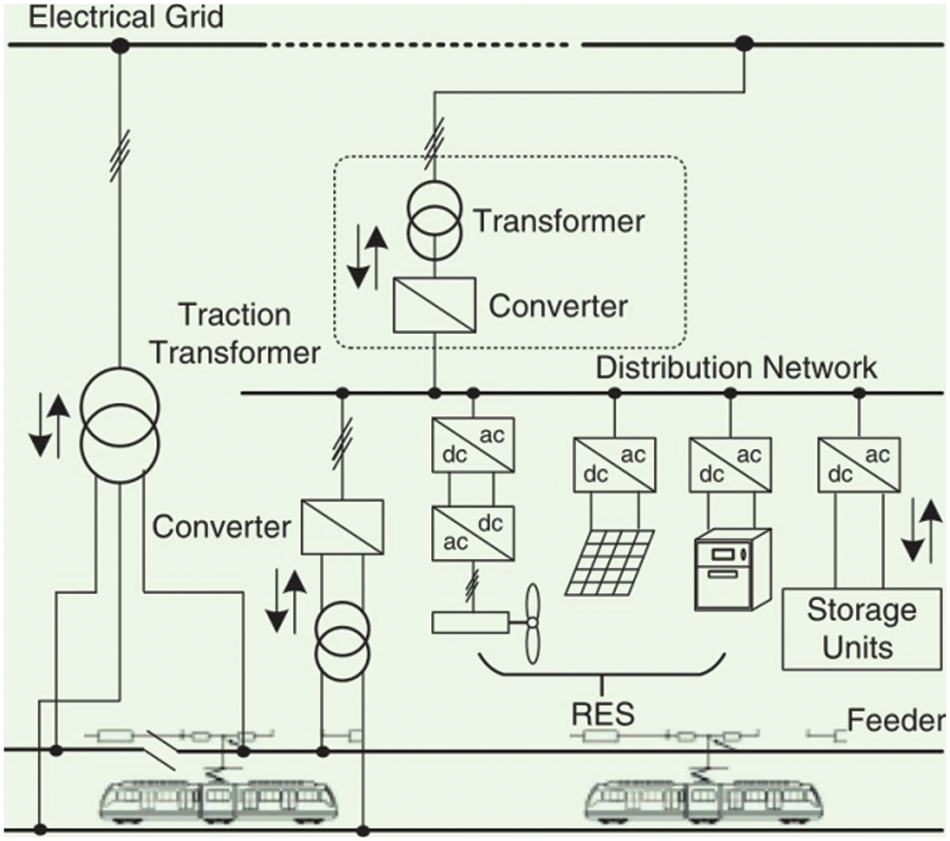
Figure 5: On-site distributed energy structure
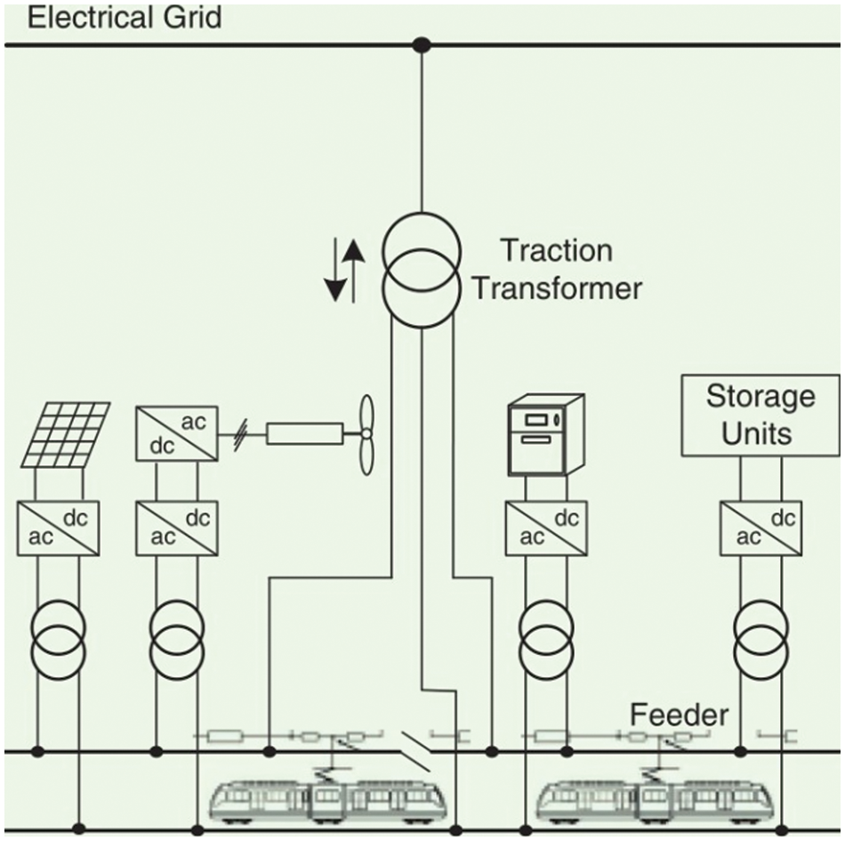
Figure 6: Integrated distributed energy structure
At present, China’s high-speed railways mainly adopt a 25 kV AC power supply [40]. Compared with an AC power supply, a two-terminal DC traction power supply system can not only avoid electromagnetic interference, voltage instability, and other problems which are often caused by AC current, but can also avoid the problem of the integrated synchronization of renewable energy, until that issue too is solved. As shown in Fig. 7, most renewable energy systems do not need additional interface circuits, which can be directly integrated. Some isolation converters can be omitted because of the DC effect. However, there is a relatively short transmission distance and high transmission loss between the two power stations, which are the urgent problems to be solved in the application of DC power supply. A high voltage (35 kV) DC power supply is under research. With the development of power electronic devices, a high-voltage DC power supply is expected to become a new power supply mode of electrified railways, which has economic and technical advantages [41]. However, due to the current constraints of existing technologies and standards, a high-voltage traction power supply system is difficult to be truly implemented in China’s railways.
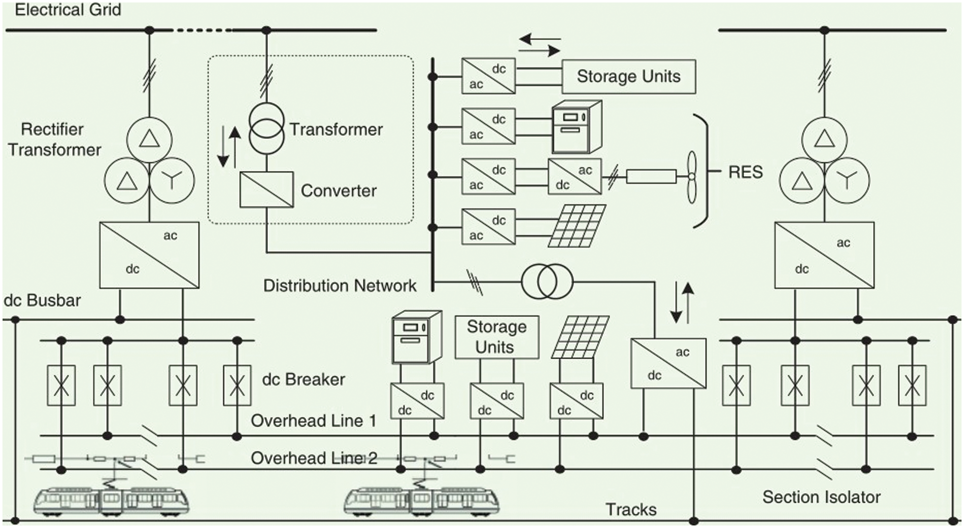
Figure 7: Structure topology of two-terminal DC traction power supply system
5 Capacity Optimization Method for Traction Transformer with New Energy and Energy Storage
Under the background of the energy internet, the near elimination of renewable energy in electrified railways will be the development direction of traction power supply system in the future [42]. Photovoltaic and wind power have high reserves and mature technology, which will be one of the main renewable energy sources connected to traction power supply systems. After photovoltaic and wind power are connected to the traction power supply system, wind power has strong fluctuation and randomness, and the train load of the traction power supply system has fluctuation [43–45]. So it is difficult to achieve a dynamic balance between power generation and load.
Therefore, it is necessary to introduce energy storage system to reduce the supply-demand imbalance between power generation and load. On the basis of the new power supply mode studied by previous scholars, several structures of combined configuration of new energy and energy storage system to optimize the capacity of traction transformer are summarized according to the characteristics of low capacity utilization of traction transformer caused by strong impact and large fluctuation of high-speed railway traction load.
5.1 Summary of Optimized Configuration
At present, there is a general problem that the capacity utilization of traction transformers is low in high-speed railways. At the same time, the daily energy supply and demand of trains and the organization of train operation show regularity, so the capacity of the hybrid storage system can be configured according to the daily load data of the traction substation. By searching for the optimal benchmark value of a hybrid energy storage system, the minimum capacity and maximum energy utilization of the traction transformers are considered as optimization objectives, and the system energy efficiency, energy storage system output, power utilization rate, and lifetime benefit are considered as constraints [46]. The optimal capacity configuration model of the traction transformer is established, and the optimal algorithm is used to solve the model and determine the system configuration scheme. Considering the structure of the traction power supply system under the access of new energy [47], a power allocation strategy suitable for the combined configuration of new energy and energy storage system is formulated. Operation condition and energy flow mechanism of the combined configuration of new energy and storage system are analyzed. Based on the functional relationship between charging and discharging datum and economic benefits, the output of new energy system, power limit of new energy and storage system, SOC charging status, and power balance are considered as constraints [48]. An optimal capacity allocation model of traction transformer under combined configuration of new energy and energy storage system is established to optimize the capacity allocation of traction transformer.
5.2 Photovoltaic Power Generation Connected to Traction Power Supply System
Photovoltaic power generation is a technology that directly converts light energy into electricity through the photovoltaic effect, which has the advantages of long life, zero-emissions and great potential for price reduction [49]. Because of its flexible installation and simple structure, photovoltaic power generation is more suitable for the integrated application of electrified railways, especially in the areas of house surface, platform canopy, railway line, and so on. For example, the Qinghai-Tibet Railway and the Lan-xin Railway pass through the resource areas of which are rich insolar energy, and there are a large number of idle land resources along the line that can be exploited and utilizedctual projects have been constructed along the Hangzhou East Station and the Jinan-Qinghai High-Speed Railway.
After the project is fully completed, the average annual power generation will be 45 million kWh, which is equivalent to about 22,000 households or 88,000 people’s annual household power consumption [50]. At present, the most common way to connect photovoltaic power generation to a traction power supply system is to connect the photovoltaic power generation system to 110 kV (or 220 kV) high voltage side of the traction substation [51]. Photovoltaic power generation is connected to the traction power supply system topology, as shown in Fig. 8. The back-to-back structure of the photovoltaic power generation system consists of two converters, which are connected to the supply arms on both sides of the traction transformer through two step-down transformers. The secondary side of the step-down transformer is connected separately to α Phase converter and to β Phase converter: two converters share a DC capacitance. The photovoltaic system uses DC/DC converter to completely boost maximum power tracking, and then the DC side of the back-to-back converter is used to achieve photovoltaic power output.
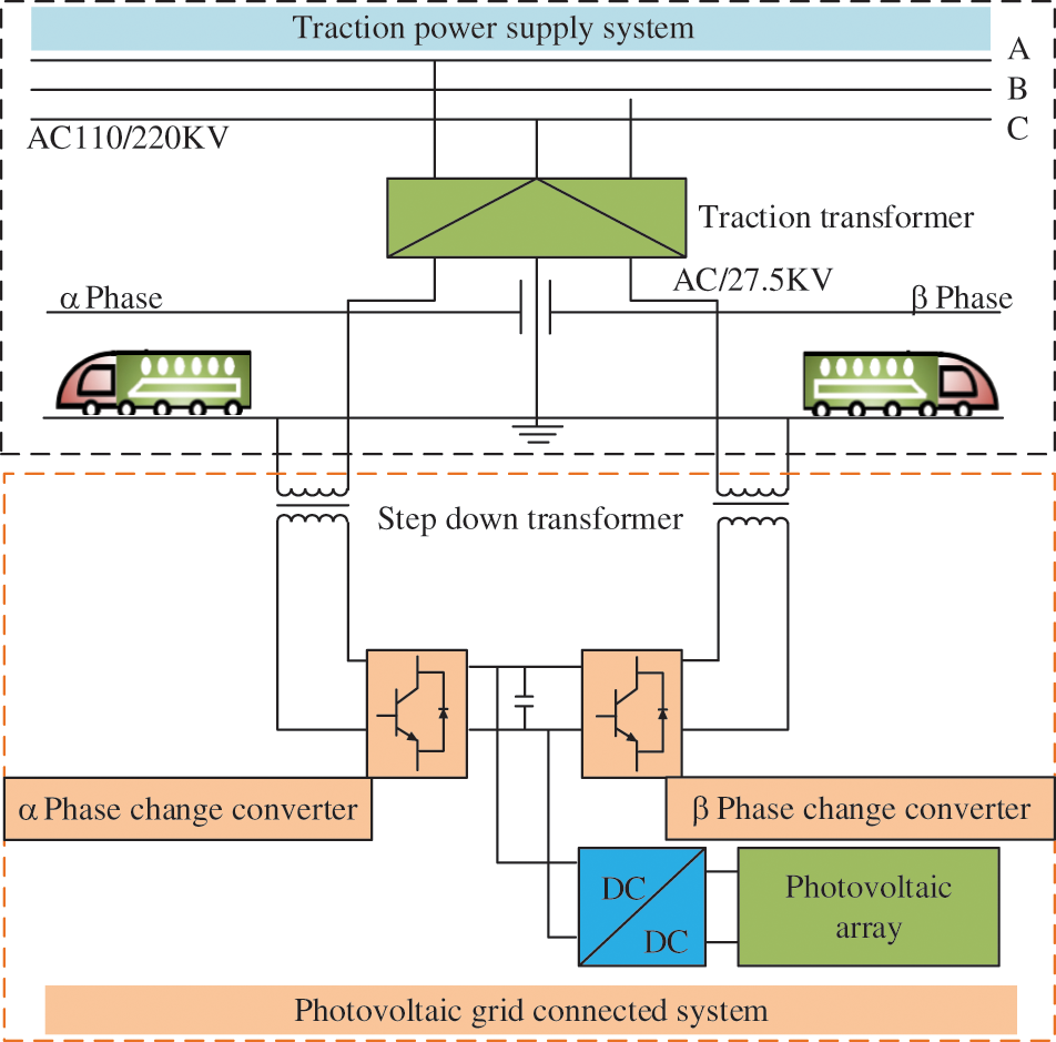
Figure 8: Topology structure of traction power supply system for photovoltaic power generation
However, due to the relatively low working voltage of photovoltaic power generation, the high-voltage side access scheme needs to undergo multi-stage high-ratio boost transformation, which results in power loss and increased system construction costs. For this reason, the document [52] puts forward a scheme that photovoltaic power generation based on a single-phase dual-port back-to-back converter can be connected to the traction power supply. The photovoltaic component can be connected to the common DC side of a single-phase back-to-back converter through DC/DC converter, which can effectively access photovoltaic. At the same time, power quality compensation at the traction side can be realized.
When the photovoltaic power generation system is connected to the traction power supply system, it can not only achieve near absorption of photovoltaic energy [53], but also optimize the capacity of the traction transformer in the traction power supply system, and the problems of unstable traction network voltage, energy-saving, and emission reduction will be solved. However, photovoltaic power generation is greatly affected by weather and the environment, so it is possible to consider the energy storage device in the system to make full use of photoelectricity.
5.3 Photovoltaic Power Generation Connected to Traction Power Supply System
With the vigorous support of clean energy and low-carbon development in China, in order to achieve the “dual-carbon” goal, China will no longer build new projects of coal and power abroad. Therefore, photovoltaic power generation technology has been continuously developed, and the rapid development of electrified railways provides a good application basis for photovoltaic power generation in traction power supply systems. However, photovoltaic power generation has the characteristics of uneven space-time distribution, and the fluctuation and intermittently of traction load are large. For this reason, photovoltaic power generation and hybrid energy storage devices in the traction power supply system are proposed in [54]. It is pointed out in the literature that using a hybrid energy storage system as the energy transfer station. The difference between supply and demand is suppressed by the charging and discharging behavior of the hybrid energy storage system, which solves the intermittent train load of the traction power supply system and the fluctuation of photovoltaic power generation and the problem that it is difficult to achieve a dynamic balance between power generation and load is solved. As shown in Fig. 9, a photovoltaic and hybrid energy storage structure is added to the traditional high-speed railway power supply system. Energy flow is achieved by a two-way DC/DC converter and RPC, and the RPC introduced also has a certain inhibitory effect on the quality of the traction power supply system. However, photovoltaic power generation has the characteristics of intermittent and fluctuation, and it is greatly affected by weather and the environment. It is prone to transient power fluctuation when it is connected to a traction power supply system. Based on the analysis of the structure of the photovoltaic system and the control strategy of the inverter, the equivalent model of the traction power supply system with photovoltaic access is constructed. The harmonic resonance characteristics and the law of change of the system are studied, and the lithium iron phosphate battery is selected as the energy storage device. Based on the working principle and modeling method of virtual synchronous generator, a power suppressing control method of photovoltaic access traction power supply system based on a virtual synchronous generator is studied [55,56]. The optimal control of the photovoltaic access traction power supply system is achieved, and the transient power fluctuation of the photovoltaic access traction power supply system is solved. At the same time, due to the access of the photovoltaic system, the problem of low capacity utilization of traction transformers has also been solved.
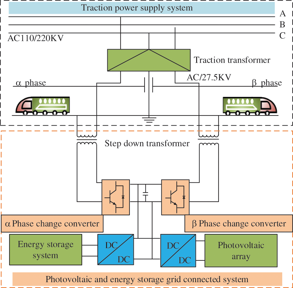
Figure 9: Structure of traction power supply system with photovoltaic and hybrid energy storage
5.4 Wind, Light, and Storage Hybrid Access System
Wind and light resources have intermittent and unstable characteristics, which lead to low utilization of wind power and photoelectric power, poor reliability and stability, and limited access power to the power grid. Considering the disadvantage of uneven space-time distribution of light resources, the document [57,58] uses a multi-energy complementary system to obtain a relatively stable total output. As shown in Fig. 10, the uncertainty of new energy is described mathematically based on the scene tree method. By establishing a mathematical model of multi-period optimal power flow, an optimized operation method of electrified railways with renewable energy and a power storage system is proposed [59]. A case study and economic evaluation of a Spanish high-speed railway line are carried out. It is pointed out that the integration can save 9.63% energy on the original basis. At the same time, the hybrid storage system can help to smooth the fluctuation of wind and light output, and make full use of the renewable characteristics of the traction loads. The energy change from one-way consumption mode to two-way interactive mode is therefoere achieved. In [60], the railway power system, which covers wind, photovoltaic renewable energy system, renewable braking energy, and hybrid energy storage system, will be optimized, and the overall effect of the integrated hybrid energy storage system will be evaluated. At present, comparing wind, light, and storage connected traction power supply system with a single new energy generation system, the former improves the stability and reliability of the power supply [61,62]. It can greatly reduce the capacity of an energy storage system and traction transformer, and better economic benefits will be obtained. Therefore, under the condition of resolving the power quality problem of wind-light entering the power network, it can be considered to connect wind, light, and storage into the traction power supply system.
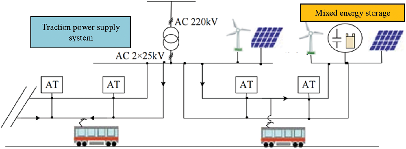
Figure 10: Wind, light, and storage hybrid access to traction power supply system
This paper summarizes the current methods for optimizing capacity allocation of traction transformers for high-speed railways. Firstly, the existing algorithms of traction transformers and the connection modes of traction transformers are summarized to optimize its capacity. The structure of the energy storage device connected to the traction power supply system is analyzed, and it is determined that the introduction of a supercapacitor into the system is more suitable for the capacity optimization of traction transformer. Then, the structure of the integrated configuration of new energy into the traction power supply system is discussed, and the possibility of optimizing the capacity of the traction transformer is presented. Finally, several configurations of an integrated configuration of new energy and traction power supply systems are discussed.
The feasibility of optimizing the capacity of the main transformer by introducing photovoltaic energy into the traction power supply system, photovoltaic and energy storage into the traction power supply system, and wind-solar energy storage hybrid into the traction power supply system are all analyzed. The capacity optimization of traction transformers will be further studied in the future. By introducing new energy and energy storage technology into the traction power supply system, the capacity optimization of the traction transformer can be realized, and the economy of the traction power supply system can be effectively improved. However, at present, the research on the topology of new energy and energy storage technology connected to the traction power supply system and the stability and power quality of the system after the connection is not deep enough. It only stays in the theoretical simulation stage, and it is not applied to engineering practice. Therefore, it is necessary to carry out relevant research to improve the economy of the traction power supply system.
Funding Statement: This work was supported in part by the National Natural Science Foundation of China (Project No. 51767015), Lanzhou Jiaotong University-Tianjin University Joint Innovation Fund Project (Project No. 2019051), and the Tianyou Innovation Team Support Program of Lanzhou Jiaotong University (No. TY202009).
Conflicts of Interest: The authors declare that they have no conflicts of interest to report regarding the present study.
References
1. Wei, W. J., Hu, H. T., Wang, K. (2019). Energy storage scheme and control strategies of high-speed railway based on railway power conditioner. Transactions of China Electrotechnical Society, 34(6), 1290–1299. [Google Scholar]
2. Popescu, M., Bitoleanu, A. (2019). A review of the energy efficiency improvement in DC railway systems. Energies, 12(6), 1092–1117. DOI 10.3390/en12061092. [Google Scholar] [CrossRef]
3. Mongkoldee, K., Kulworawanichpong, T. (2021). Optimal sizing of ac railway power conditioner in autotransformer-fed railway power supply system. International Journal of Electrical Power & Energy Systems, 127(3), 106628–106643. DOI 10.1016/j.ijepes.2020.106628. [Google Scholar] [CrossRef]
4. Wang, K., Hu, H. T., Chen, J. Y. (2019). System-level dynamic energy consumption evaluation for high-speed railway. IEEE Transactionson Transportation Electrification, 5(3), 745–757. DOI 10.1109/TTE.6687316. [Google Scholar] [CrossRef]
5. Hu, H. T., Tao, H. D., Blaabjerg, F. (2018). Train-network interactions and stability evaluation in high-speed railways–Part I: Phenomena and modeling. IEEE Transactions on Power Electronic, 33(6), 4627–4642. DOI 10.1109/TPEL.63. [Google Scholar] [CrossRef]
6. Ma, F., Wang, X., Deng, L., Zhu, Z., Xu, Q. et al. (2019). Multi-port railway power conditioner and its management control strategy with renewable energy access. IEEE Journal of Emerging and Selected Topics in Power Electronics, 2019, 1–9. [Google Scholar]
7. Hong, Z., Ying, H., Qi, L., Chen, W. (2016). Design of energy management system for fuel cell/Supercapacitor hybrid locomotive. IEEE Vehicle Power and Propulsion Conference (VPPC), pp. 1–5. Hangzhou, China. [Google Scholar]
8. Wang, H., Wang, T., Xie, X., Ling, Z., Dong, X. (2018). Optimal capacity configuration of a hybrid energy storage system for an isolated microgrid using quantum-behaved particle swarm optimization. IEEE Transactions on Instrumentation and Measurement, 65(3), 549–558. [Google Scholar]
9. Liu, Z., Hao, F., Chen, J., Zhang, G. (2019). Optimization method of train-ground coordination parameters for urban traction power supply system. Journal of Beijing Jiaotong University, 43(1), 79–87. [Google Scholar]
10. Li, Q. Z., Wang, X. J., Huang, X. H. (2019). Research on flywheel energy storage technology for electrified railway. Proceedings of the CSEE, 39(7), 2025–2033. [Google Scholar]
11. Liu, R. X. (2019). Capacity optimization algorithm of traction transformer in electrified railway. IEEE 28th International Symposium on Industrial Electronics (ISIE), pp. 1737–1742. Vancouver, Canada. [Google Scholar]
12. Guo, X., Li, C., Zheng, Z., Li, Y. (2020). Optimization of medium-frequency transformers with large capacity and high insulation requirement. 22nd European Conference on Power Electronics and Applications (EPE’20 ECCE Europe), pp. 1–9. Lyon, France. [Google Scholar]
13. Zhang, K., Chen, W., Cao, X., Song, Z., Sun, L. (2018). Optimization design of high-power high-frequency transformer based on multi-objective genetic algorithm. IEEE International Power Electronics and Application Conference and Exposition (PEAC), pp. 1–5. Shenzhen, China. DOI 10.1109/PEAC.2018.8590371. [Google Scholar] [CrossRef]
14. Zhang, L., Li, D., Chen, L., Zhao, J., Rao, X. (2021). Transformer load capacity assessment and optimized control strategy of cooling system. IEEE 4th International Electrical and Energy Conference (CIEEC), pp. 1–4. Wuhan, China. [Google Scholar]
15. Yao, P., Jiang, X., Xue, P., Li, S., Wang, F. (2021). Design optimization of medium-frequency transformer for DAB converters with DC bias capacity. IEEE Journal of Emerging and Selected Topics in Power Electronics, 9(4), 5043–5054. DOI 10.1109/JESTPE.2020.3010155. [Google Scholar] [CrossRef]
16. Ge, S. Y., Zhang, K., Liu, H. (2013). Optimization of contact structure among main transformers considering unit power supply capacity cost. Advanced Materials Research, 805(1), 788–792. DOI 10.4028/www.scientific.net/AMR.805-806.788. [Google Scholar] [CrossRef]
17. Zhang, D., Zhang, Z., Wang, W., Yang, Y. (2015). Negative sequence current optimizing control based on railway static power conditioner in V/v traction power supply system. IEEE Transactions on Power Electronics, 31(1), 200–212. DOI 10.1109/TPEL.2015.2404934. [Google Scholar] [CrossRef]
18. Xiong, Y., Yao, D., Yang, Z., Zhang, B., Sun, J. (2012). The electric power saving schemes of high-speed electrified railway. Energy Procedia, 16(1), 1940–1947. DOI 10.1016/j.egypro.2012.01.297. [Google Scholar] [CrossRef]
19. Deng, W. L., Dai, C. H., Chen, W. R. (2020). Research progress of railway power conditioner. Proceedings of the CSEE, 40(14), 460–4655 + 4742. [Google Scholar]
20. Cheng, P., Kong, H., Ma, J. (2020). Evolution toward resilient traction power supply systems of railways with interconnected microgrids. CSEE Journal of Power and Energy Systems, 2020, 1–11. [Google Scholar]
21. Wu, M. L., Dai, C. H., Deng, W. L. (2018). Back-to-back PV generation system and its control strategy for electrified railway. Power System Technology, 42(2), 541–547. [Google Scholar]
22. Cui, G. P., Jia, L., Su, Z. H. (2021). SMES-Battery hybrid energy storage system integrated railway power conditioner for peak load shifting and power quality improvement in high-speed electrical railway. 24th International Conference on Electrical Machines and Systems, pp. 2246–2250. Gyeongju, Korea. [Google Scholar]
23. Wu, S., Wu, M., Wang, Y. (2021). A novel Co-phase power-supply system based on modular multilevel converter for high-speed railway AT traction power-supply system. Energies, 14(1), 253–266. DOI 10.3390/en14010253. [Google Scholar] [CrossRef]
24. Cui, G., Luo, L., Liang, C. (2019). Supercapacitor integrated railway static power conditioner for regenerative braking energy recycling and power quality improvement of high-speed railway system. IEEE Transactions on Transportation Electrification, 5(3), 702–714. DOI 10.1109/TTE.6687316. [Google Scholar] [CrossRef]
25. Foroutan, F., Gazafrudi, S., Shokri-Ghaleh, H. (2020). A comparative study of recent optimization methods for optimal sizing of a green hybrid traction power supply substation. Archives of Computational Methods in Engineering, 28(4), 2351–2370. DOI 10.1007/s11831-020-09456-8. [Google Scholar] [CrossRef]
26. de la Torre, S., Sanchez-Racero, A. J., Aguado, J. A., Reyes, M. (2015). Optimal sizing of energy storage for regenerative braking in electric railway systems. IEEE Transactions Power Systems, 30, 1492–1500. DOI 10.1109/TPWRS.2014.2340911. [Google Scholar] [CrossRef]
27. Huan, X., Huai, X. C., Zhong, P. Y. (2015). Optimal energy management location and size for stationary energy storage system in a metro line based on genetic algorithm. Energies, 8(10), 11618–11640. DOI 10.3390/en81011618. [Google Scholar] [CrossRef]
28. Arabahmadi, M., Banejad, M., Dastfan, A. (2021). Hybrid compensation method for traction power quality compensators in electrified railway power supply system. Global Energy Interconnection, 4(2), 158–168. DOI 10.1016/j.gloei.2021.05.008. [Google Scholar] [CrossRef]
29. Ping, P. S., Zhen, B. Z., Hui, D. (2021). A novel power control strategy for MMC-RPC. Electric Power Automation Equipment, 38(1), 52–58. [Google Scholar]
30. Ma, Q., Guo, X., Luo, P. (2018). A novel railway power conditioner based on super capacitor energy storage system. Transactions of China Electrotechnical Society, 33(6), 1208–1218. [Google Scholar]
31. Zhao, L., Chen, F., Jiang, Y. (2020). Research on topology and control strategy of railway power regulator based on MMC. 2020 5th International Conference on Power and Renewable Energy (ICPRE), pp. 6–15. Shanghai, China. [Google Scholar]
32. Li, Z. J., Yang, X. F., Tao, H. B. (2020). An improved modular multilevel converter based symmetrical integrated super capacitor energy storage system. Proceedings of the CSEE, 40(5), 1617–1631. [Google Scholar]
33. Quraan, M., Tricoli, P., D’Arco, S. (2017). Efficiency assessment of modular multilevel converters for battery electric vehicles. IEEE Transactions on Power Electronics, 32(3), 2041–2051. [Google Scholar]
34. Yang, X. F., Xue, Y., Chen, B. W. (2017). Reverse-blocking modular multilevel converter for battery energy storage systems. Journal of Modern Power Systems and Clean Energy, 5(4), 652–662. DOI 10.1007/s40565-017-0300-5. [Google Scholar] [CrossRef]
35. Roudsari, H. M., Jalilian, A., Jamali, S. (2018). Flexible fractional compensating mode for railway static power conditioner in a V/v traction power supply system. IEEE Transactions on Industrial Electronics, 65(10), 7963–7974. DOI 10.1109/TIE.2018.2801779. [Google Scholar] [CrossRef]
36. Geng, A. Q., Hu, H. T., Zhang, Y. W. (2021). Control strategy of hybrid energy storage system for electrified railway based on increment energy management. Transactions of China Electrotechnical Society, 36(23), 4916–4925. [Google Scholar]
37. Luo, J. M., Wei, X. J., Gao, S. B. (2021). Summary and outlook of capacity configuration and energy management technology of high-speed railway energy storage system. Proceedings of the CSEE, 1, 1–21. [Google Scholar]
38. Aguado, J. A., Sánchez Racero, A. J., Torre, S. (2018). Optimal operation of electric railways with renewable energy and electric storage systems. IEEE Transactions on Smart Grid, 9(2), 993–1001. DOI 10.1109/TSG.2016.2574200. [Google Scholar] [CrossRef]
39. Boudoudouh, S., Maaroufi, M. (2018). Renewable energy sources integration and control in railway microgrid. IEEE Transactions on Industry Applications, 55(2), 2045–2052. DOI 10.1109/TIA.2018.2878143. [Google Scholar] [CrossRef]
40. Perez, F., Iovine, A., Damm, G., Galai-Dol, L., Ribeiro, P. F. (2020). Stability analysis of a DC microgrid for a smart railway station integrating renewable sources. IEEE Transactions on Control Systems Technology, 28(5), 1802–1816. DOI 10.1109/TCST.87. [Google Scholar] [CrossRef]
41. Liang, J., Huang, R., Wang, P. (2021). Optimal operation of a multi-energy hub for minimal energy usage cost. IOP Conference Series: Earth and Environmental Science, Xiamen, China, 675(1), 121–127. DOI 10.1088/1755-1315/675/1/012127. [Google Scholar] [CrossRef]
42. An, B., Li, Y., Guerrero, W. (2021). Renewable energy integration in intelligent railway of China: Configurations, applications and issues. IEEE Intelligent Transportation Systems Magazine, 13(3), 13–33. DOI 10.1109/MITS.2019.2953482. [Google Scholar] [CrossRef]
43. Kalidas, M., Lavanya, B. (2016). Hybrid power quality compensator for traction power system with photovoltaic array. International Journal for Modern Trends in Science and Technology, 2(7), 79–86. [Google Scholar]
44. Zhang, G., Tian, Z. B., Du, H. Q. (2018). A novel hybrid DC traction power supply system integrating PV and reversible converters. Energies, 11(7), 1661. DOI 10.3390/en11071661. [Google Scholar] [CrossRef]
45. Jaffery, S., Khan, M., Ali, L. (2014). The potential of solar powered transportation and the case for solar powered railway in Pakistan. Renewable and Sustainable Energy Reviews, 39, 270–276. DOI 10.1016/j.rser.2014.07.025. [Google Scholar] [CrossRef]
46. Pankovits, P., Pouget, J., Robyns, B., Delhaye, F., Brisset, S. (2014). Towards railway-smartgrid: Energy management optimization for hybrid railway power substations. Proceedings of the IEEE PES Innovative Smart Grid Technologies, vol. 12, pp. 1–6. Istanbul, Turkey. [Google Scholar]
47. Sengor, I., Kilickiran, H. C., Akdemir, H., Kekezoglu, B., Erdinc, O. (2018). Energy management of a smart railway station considering regenerative braking and stochastic behaviour of ESS and PV generation. IEEE Transactions on Sustainable Energy, 9, 1041–1050. DOI 10.1109/TSTE.5165391. [Google Scholar] [CrossRef]
48. Roch-Dupre, D., Lopez, A. J., Pecharroman, R. R., Cucala, A. P., Fernandez-Cardador, A. (2017). Analysis of the demand charge in DC railway systems and reduction of its economic impact with energy storage systems. International Journal of Electrical Power and Energy Systems, 2017(93), 459–467. DOI 10.1016/j.ijepes.2017.06.022. [Google Scholar] [CrossRef]
49. Brenna, M., Foiadelli, F., Kaleybar, H. J. (2020). The evolution of railway power supply systems toward smart microgrids: The concept of the energy hub and integration of distributed energy resources. IEEE Electrification Magazine, 8(1), 12–23. DOI 10.1109/MELEC.6508996. [Google Scholar] [CrossRef]
50. An, B., Li, Y., Xiao, H. (2020). Magnetic-integrated multipulse rectifier transformer with a tight impedance equalizing strategy for power quality improvement of DC traction power supply system. IEEE Transactions on Industrial Electronics, 67(8), 6270–6279. DOI 10.1109/TIE.41. [Google Scholar] [CrossRef]
51. Zhong, Z., Zhang, Y., Shen, H., Li, X. (2020). Optimal planning of distributed photovoltaic generation for the traction power supply system of high-speed railway. Journal of Cleaner Production, 13(2), 263–289. DOI 10.1016/j.jclepro.2020.121394. [Google Scholar] [CrossRef]
52. Xu, W., Xiao, X. G., Chen, P. W. (2018). Overview of key microgrid technologies. International Transactions on Electrical Energy Systems, 28, 1–22. [Google Scholar]
53. Ko, R., Jo, H. C., Joo, S. K. (2019). Energy storage system capacity sizing method for peak-demand reduction in urban railway system with photovoltaic generation. Journal of Electrical Engineering and Technology, 14(4), 1771–1775. DOI 10.1007/s42835-019-00203-z. [Google Scholar] [CrossRef]
54. Hu, H. T., Ge, Y. B., Huang, Y. (2020). A novel “source-network-train-storage” integrated power supply system for electric railways. Proceedings of the CSEE, 2020, 1–18. [Google Scholar]
55. Wang, H., Lv, Q., Geng, Y. (2017). Siting and sizing method of energy storage system of microgrid based on power flow sensitivity analysis. The Journal of Engineering, 2017(13), 1974–1978. DOI 10.1049/joe.2017.0674. [Google Scholar] [CrossRef]
56. Razik, L., Berr, N., Khayyam, S. (2018). REM-S--Railway energy management in real rail operation. IEEE Transactions on Vehicular Technology, 68(2), 1266–1277. DOI 10.1109/TVT.2018.2885007. [Google Scholar] [CrossRef]
57. Ponci, F., Monti, A., Khayyam, S. (2018). Railway system energy management optimization demonstrated at offline and online case studies. IEEE Transactions on Intelligent Transportation Systems, 19(11), 3570–3583. DOI 10.1109/TITS.2018.2855748. [Google Scholar] [CrossRef]
58. Hou, W., Tian, G., Lei, G. (2017). Cooperative mechanism for energy transportation and storage in Internet of energy. IEEE Access, 5, 1363–1375. DOI 10.1109/ACCESS.2017.2664981. [Google Scholar] [CrossRef]
59. Huang, W. J., Zhang, N., Cheng, Y. (2020). Multi-energy networks analytics: Standardized modeling, optimization and low carbon analysis. Proceedings of the IEEE, 108(9), 1411–1436. [Google Scholar]
60. Sang, Z. X., Huang, J. Q., Du, Z. (2021). The power optimization on tie-line for the island energy internet based on interactive distribution network. Sustainable Energy Technologies and Assessments, 45(6), 101148. DOI 10.1016/j.seta.2021.101148. [Google Scholar] [CrossRef]
61. Liu, Y. L., Chen, M. W., Lu, S. F., Chen, Y. Y., Li, Q. Z. (2018). Optimized sizing and scheduling of hybrid energy storage systems for high-speed railway traction substations. Energies, 11(9), 2199–2227. DOI 10.3390/en11092199. [Google Scholar] [CrossRef]
62. Perdana, Y. S., Muyeen, S. M., Al-Durra, A., Morales-Paredes, H. K., Simes, M. G. (2019). Direct connection of supercapacitor–battery hybrid storage system to the grid-tied photovoltaic system. IEEE Transactions on Sustainable Energy, 10(3), 1370–1379. DOI 10.1109/TSTE.5165391. [Google Scholar] [CrossRef]
Cite This Article
 Copyright © 2022 The Author(s). Published by Tech Science Press.
This work is licensed under a Creative Commons Attribution 4.0 International License , which permits unrestricted use, distribution, and reproduction in any medium, provided the original work is properly cited.
 Downloads
 Citation Tools