
 Submit a Paper
 Propose a Special lssue
 Open Access
ARTICLE
Experiment Study on the Exhaust-Gas Heat Exchanger for Small and Medium-Sized Marine Diesel Engine
1 School of Mechanical Engineering, Nantong University, Nantong, 226019, China
2 School of Mechanical Engineering, Nantong Institute of Technology, Nantong, 226019, China
* Corresponding Author: Guannan Xi. Email:
Energy Engineering 2023, 120(1), 125-145. https://doi.org/10.32604/ee.2022.022295
Received 03 March 2022; Accepted 08 June 2022; Issue published 27 October 2022
 View Full Text
 Download PDF
Abstract
This paper aims to design a special exchanger to recover the exhaust gas heat of marine diesel engines used in small and medium-sized fishing vessels, which can then be used to heat water up to 55°C–85°C for membrane desalination devices to produce fresh water. A new exhaust-gas heat exchanger of fins and tube, with a reinforced heat transfer tube section, unequal spacing fins, a mixing zone between the fin groups and four routes tube bundle, was designed. Numerical simulations were also used to provide reference information for structural design. Experiments were carried out for exhaust gas waste heat recovery from a marine diesel engine in an engine test bench utilizing the heat exchanger. The experimental results show that the difference between heat absorption by water and heat reduction of exhaust gas is less than 6.5%. After the water flow rate was adjusted, the exhaust gas waste heat recovery efficiency was higher than 70%, and the exhaust-gas heat exchanger’s outlet water temperature was 55°C–85°C at different engine loads. This means that the heat recovery from the exhaust gas of a marine diesel engine meets the requirement to drive a membrane desalination device to produce fresh water for fishers working in small and medium-sized fishing vessels.Keywords
The number of fishing vessels in China ranks first globally. As the main power source of the ships, marine diesel engines have a thermal efficiency of 40% to 45% [1–3], but more than half of the heat is discharged in the form of cylinder liner water and exhaust gas, of which exhaust gas heat accounts for 20%–35% of the total calorific value of diesel, and the exhaust gas temperature is 200°C–400°C under full working condition [4–6]. On the other hand, the offshore fishing cycle of fishers driving small and medium-sized fishing vessels to sea is about 7–10 days. Sometimes, fishing will take another several days if the vessel's cabin is not fully loaded with fish. When the ship is going out to the sea, a lot of freshwater is carried for fishers living on the sea to drink. However, the fresh water easily deteriorates over longer term storage, especially during the summer, and the metamorphic water as a drink is harmful to the fishers’ health. To solve this problem then, seawater desalination devices need to be installed in small and medium-sized fishing vessels. Membrane distillation is such a type of device. It needs only 55°C–85°C hot water as a heat source to drive its water production parts [7–11] and produces 10 L/h fresh water. Suppose the heat recovered from the exhaust gas of a marine diesel engine is enough as a heat source for the seawater desalination. In that case, fishers can get endless fresh water while fishing upon the sea [12]. Therefore, heat recovery from the diesel engine exhaust gas is significant and has a high application value.
Many types of research have previously been carried out on the use of waste heat from diesel engines. Lu et al. [13] improved the Coefficiency of performance (COP) of three sorption refrigerators driven by diesel exhaust gas with a pressurized thermal and multi-step recovery process. In order to recover waste heat from a marine gas turbine and improve the thermal efficiency of a ship part load, Hou et al. [14] proposed technology of a combined supercritical CO2 recompression and heat recovery cycle. This technology applied to the waste heat recovery of marine gas turbines and has the advantages of high waste heat utilization, compactness, and low cost. Wang et al. [15] built a dynamic mathematical model of a natural gas engine waste heat recovery unit and simulated static and dynamic characteristics under five typical operating conditions. He et al. [16] proposed a mathematical model of a thermoelectric generator considering the effect of temperature gradients in the flow direction and investigated the effect of fluctuations in exhaust gas parameters on the maximum power output performance of the corresponding thermoelectric generator. The results showed that the optimum design areas were 0.22 and 0.3 m2 for down-flow and counter-flow, respectively, with the counter-flow arrangement being more effective. Choi et al. [17] used a porous medium equipped with a customized thermoelectric module to assist the thermoelectric generator in recovering waste heat from a diesel engine. The experimental results showed that at a maximum engine speed of 1400 rpm, the lowest porosity of 0.12 was used to obtain 98 W of maximum power output with a maximum energy conversion efficiency of only 3%. Ji et al. [18] used a thermoelectric generator to convert waste heat directly into electrical energy. Based on an analysis of the differences, the height of the thermoelectric module was found to be the most important design parameter affecting the thermoelectric module. Aghaali et al. [19] made the exhaust gas energy recovery more efficient by applying different techniques and the concept of a turbo-compound engine that could provide more energy. Yerne et al. [20] theoretically investigated a single tube coreless heat pipe heat exchanger (thermosiphon) simulating diesel engine exhaust conditions. It could be concluded that the efficiency of the thermal siphon exceeded 50% for each condition, increasing to 88% at 350°C as the inlet hot air velocity was reduced to 1 m/s. It was also observed that the efficiency of the thermosiphon was lowest when the heat capacity of the hot fluid was equal to that of the cold fluid. Shafieian et al. [21] presented a new multifunctional desalination, cooling and air conditioning recovery system to recover the exhaust gas from a submarine engine and the waste heat from the cooling water. The system was mathematically modeled based on the actual thermophysical parameters and the engine’s exhaust gas. Liang et al. [22] proposed a regenerative supercritical carbon dioxide Brayton cycle/organic Rankine cycle dual-loop tandem utilizing the heat discharged from the twin engines to address the problem of difficult waste heat recovery from the high-temperature exhaust gas. The results showed that the maximum net content of this system outputted the power up to 41 kW, so the dual-fuel engine outputted power increased by 6.8%.
Much of the prior research focused on waste heat recovery for diesel engine exhaust gas for large vessels; the heat recovery efficiency was relatively low. However, there were few studies on producing fresh water by using the waste heat of small and medium-sized fishing vessels. Large vessels usually use a Waste Heat Recovery (WHR) steam plant to recover heat from the exhaust gas, characterized mainly by a Heat Recovery Steam Generator (HRSG), and generally including a steam turbine, in some cases a power gas turbine, pumps, heat exchangers, as well as electric machinery [23]. However, the space of the small and medium-sized fishing vessels is small. The existing exhaust gas waste heat recovery systems are also costly, bulky and unsuitable for small and medium-sized fishing vessels. Therefore, it is imperative to design a compact and efficient exhaust-gas heat exchanger to recover the exhaust gas heat of small and medium-sized marine diesel engines. While designing the structure of the exhaust-gas heat exchanger, flow simulations were also done to provide reference information. In this paper, the exhaust gas waste heat recovery rate experiment was carried out on the bench circuit. The experimental parameters of the exhaust-gas heat exchanger were sampled, such as the water flow rate, the inlet, the outlet water temperature, and the exhaust gas temperature. This paper aims to obtain the outlet water of the exhaust-gas heat exchanger with a temperature of 55°C–85°C, and a heat larger than 38 kW [24]. The heat of 38 kW is a minimum heat source to drive a membrane distillation producing 10 L/h fresh water. As for heat recovery efficiency of the exhaust gas, it is about 70%. In this way, the waste heat recovery of small and medium-sized fishing vessel exhaust gas becomes high practical application values. Meanwhile, energy consumption and carbon dioxide emissions can be reduced when exhaust gas heat from small and medium-sized marine diesel engines is recovered, which is beneficial to carbon peaking and carbon neutralization.
2 Exhaust Gas Waste Heat from Marine Diesel Engine
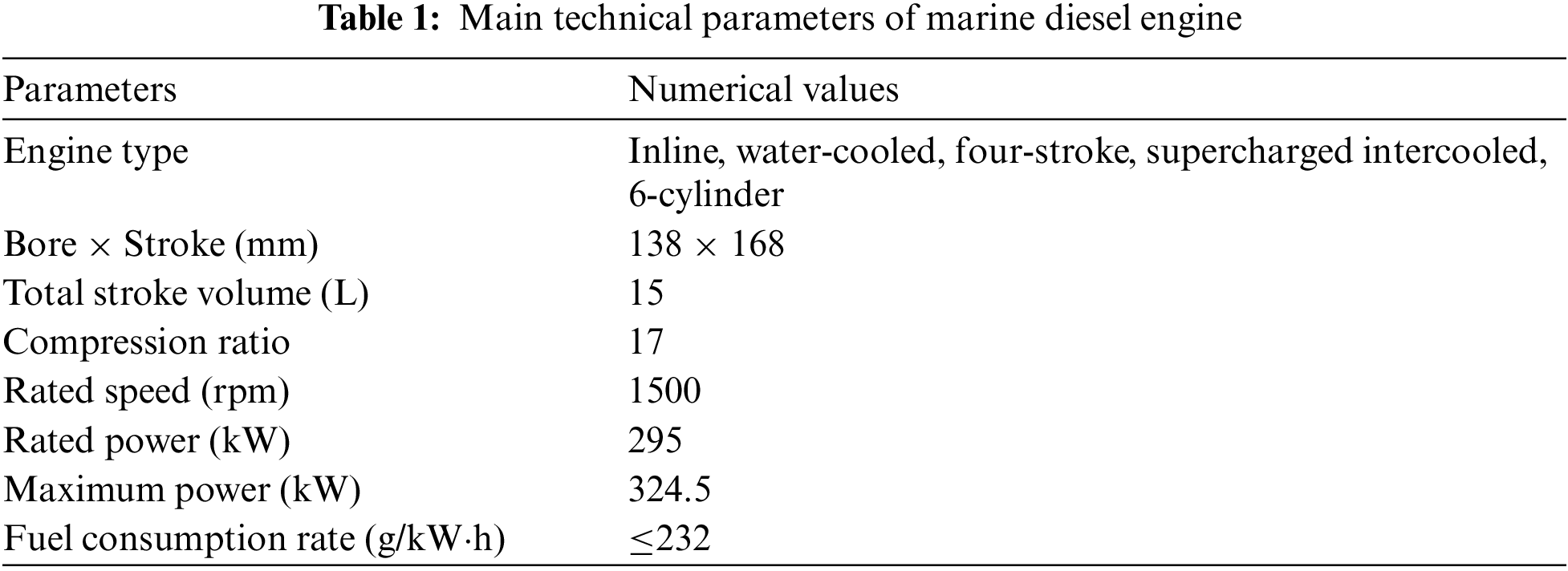
Fig. 1 shows a marine diesel engine test device used in the experiment. The marine diesel engine consists of a turbine, intercooler, internal plate heat exchanger, and double-pipe heat exchanger. A turbine increases the temperature and pressure of the inlet air. After being cooled by the intercooler, the air enters the diesel engine to participate in combustion. And the double-pipe heat exchanger is installed before the exhaust gas pipe to cool exhaust gas by the external circulating water. The purpose of this is to decrease the exhaust gas temperature and keep the ship's operation safe. With the exhaust gas temperature monitoring point E, as shown in Fig. 1, at the rear of the turbine, can provide real-time monitoring of the exhaust gas outlet temperature of the marine diesel engine under different loads. The marine diesel engine test device has one internal and one external circulating water circuit to transfer heat through an internal plate heat exchanger, which can carry excess heat from the engine body. If the internal circulating water temperature is too high, the volume flow rate of the external circulating water can be increased to take away more heat from the engine. Water temperature monitoring points are set up at four points, that is, a point, the inlet of the external circulating circuit, b point, the outlet of the external circulating circuit, c point, the inlet of the internal plate heat exchanger, and d point, the outlet of internal plate heat exchanger with the internal circulating water circuit. Table 1 shows the marine diesel engine-specific operating parameters. The marine diesel engine to be tested is four-strokes, and 6-cylinders and the rated power and speed are 295 kW and 1500 rpm, respectively.
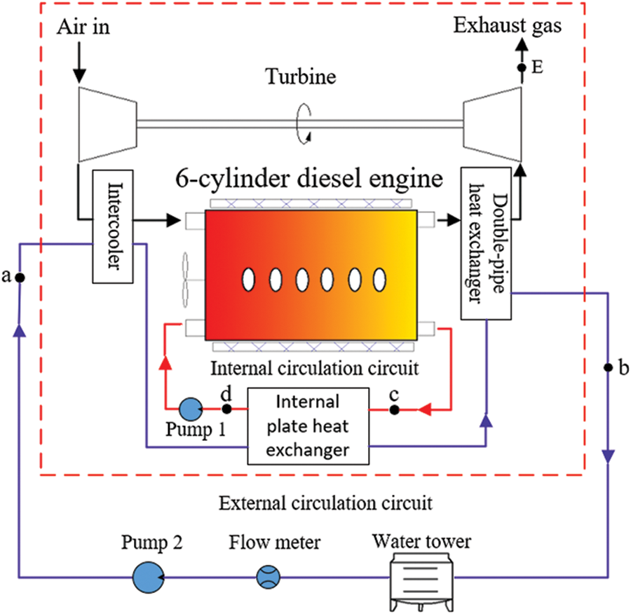
Figure 1: Diesel engine test device
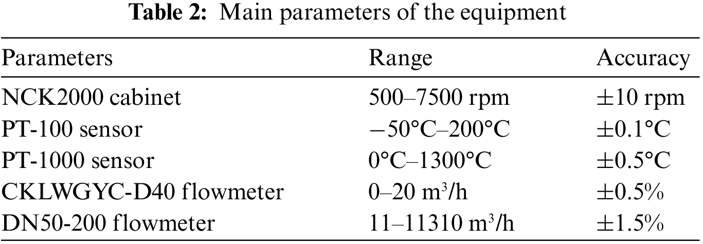
The marine diesel engine rotation speed and load are controlled by an NCK2000 cabinet. One PT-1000 sensor is used to measure the exhaust gas temperature at point E, and four PT-100 sensors are used to measure the water temperatures at points a, b, c to d. A CKLWGYC-D40 turbine flowmeter and DN50-200 insertion exhaust gas flowmeter are used to measure the external circulating water flow rate and exhaust gas mass flow rate, respectively. The specific parameters of the experimental equipment are shown in Table 2.
There is a strong non-linearity and time lag between the cooling water system and exhaust gas emission system [25]. To solve this problem, the diesel engine is set to run for at least 10 min at each specified working condition. After the ten minutes, it works stably, and the errors are greatly reduced then multiple measurements at the same temperature point are carried out. With temperature values with large fluctuations excluded from multiple measurements, the average value is taken, ensuring signal acquisition accuracy and comprehensiveness.
2.2 Test Result and Discussion
As the marine diesel engine is equipped with a double-pipe heat exchanger, the external circulating cooling water will take away a part of the exhaust gas heat and reduce exhaust gas outlet temperature through the double-pipe heat exchanger. Therefore, it is necessary to find the appropriate external circulating cooling water flow rate, which can reduce heat loss of exhaust gas and make the diesel engine operate stably simultaneously. And then, the exhaust-gas heat exchanger can recover more heat from the exhaust gas to drive the membrane desalination device.
With the changes in external circulating water flow rate, the exhaust gas temperature at point E and water temperature at point c, the inlet of internal plate heat exchanger in internal circulating water, are shown in Table 3. As shown in Table 3, when the external circulating water flow rate is 10 m³/h and the marine diesel engine load is from 60% to 100%, the internal circulating water temperature at point c is higher than 80°C, which is not conducive to the long-term operation of marine diesel engine [26,27]. When the external circulating water flow rate is 13 m³/h and 18 m³/h, the internal circulating water temperature at point c under different loads is lower than the limit temperature of stable operation 80°C. With the external circulating cooling water’s water flow rate increasing, the exhaust gas’s heat carried by the double-pipe heat exchanger increases, which leads to the decrease of the outlet temperature at measurement point E of the exhaust gas. Compared with 18 m³/h, external circulating water carries less exhaust gas heat at the flow rate of 13 m³/h through a double-pipe heat exchanger, and this leads to a higher exhaust gas outlet temperature of marine diesel engines, which is conducive to recovering more exhaust gas heat. Therefore, this paper will be based on the external circulating water flow rate of 13 m³/h to calculate the exhaust gas heat.
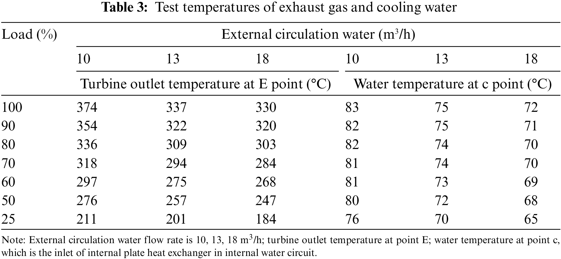
Fig. 2 depicts the mass flow rate and volume flow rate of exhaust gas under 25%–100% load of diesel engine, and the velocity of exhaust gas in the exhaust gas outlet pipe. As a load of marine diesel engine increases, exhaust gas flow rate and its velocity increases linearly. The pipe’s mass flow rate, volume flow rate, and velocity are about 1030–1750 kg/h, 825–1365 m³/h, and 28–50 m/s. Typically, the exhaust temperature is between 200°C and 400°C, and the exhaust gas pressure is slightly higher than atmospheric pressure. Therefore, the exhaust gas can be treated as a mixture of an ideal gas [28]. According to the formula (1), the recoverable heat of exhaust gas can be calculated:
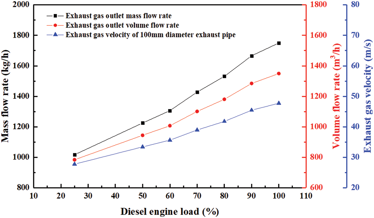
Figure 2: Exhaust gas mass flow, volume flow, and flow rate
where
In Fig. 2, the external circulating water flow rate of the marine diesel engine is 13 m³/h. As the load of the marine diesel engine increases, the minimum recoverable heat of exhaust gas is calculated at about 58 kW, and the maximum recoverable heat of exhaust gas is calculated at about 172 kW, based on the exhaust gas temperature at the outlet of the turbine measuring at point E, the exhaust gas mass flow rate and volume flow rate.
In order to protect the water quality of the membrane desalination device, an additional seawater heat exchanger is added, which can transfer heat to the membrane desalination device from the hot water of the exhaust-gas heat exchanger. The membrane desalination device to be driven requires 30 kW of heat. The seawater heat exchanger’s heat exchange efficiency is about 80% [29], indicating that the heat recovery from exhaust gas needs to be greater than 38 kW. The inlet water temperature of the exhaust-gas heat exchanger is 20°C, and the outlet water temperature needs to reach 55°C–85°C. Therefore, the water temperature of the seawater desalination membrane module circuit can be 50°C–80°C by the seawater heat exchanger. The inlet and outlet water temperatures of the seawater heat exchanger are shown in Fig. 3.
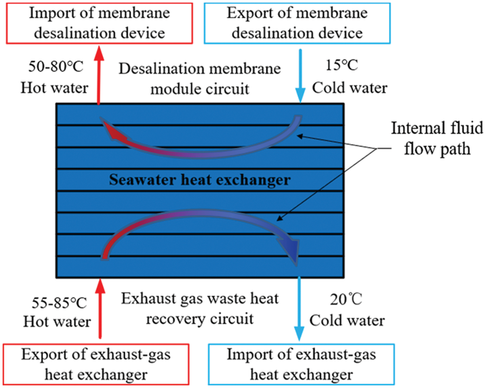
Figure 3: The inlet and outlet water temperature of the seawater heat exchanger
3 Design of Exhaust-Gas Heat Exchanger
3.1 Heat Transfer Area Calculation
The method of the exhaust gas heat recovery begins with the transferring of exhaust gas heat to the circulating water in the heat exchanger. The fin and tube structure heat exchanger is suitable for gas-liquid heat transfer [30] and has a large heat transfer area in a compact space. The windward surface of the exhaust gas entering the heat exchanger is small, and the exhaust gas flow rate is high. The exhaust gas enters the heat exchanger unevenly, which reduces the recovery rate of exhaust gas heat. The 2D model of the exhaust-gas heat exchanger is shown in Fig. 4. A reinforced heat transfer tube section is placed before the heat exchanger to disturb the exhaust gas. The fin part adopts an unequal spacing arrangement with a dense middle and sparse sides, which can improve exhaust gas resistance in the heat exchanger’s middle. There is a mixing zone between the two fins group with an interval of 100 mm so that the exhaust gas is evenly mixed when passing through this particular zone.
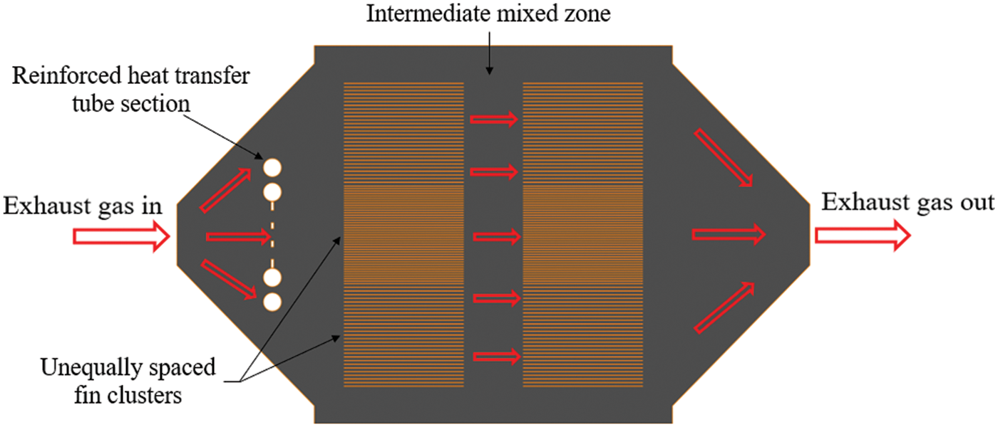
Figure 4: 2D model of exhaust-gas heat exchanger
The flow medium in heat exchanger consists of hot fluid and cold fluid. The hot fluid is high-temperature exhaust gas, and the cold fluid is liquid water. The maximum recoverable heat
Logarithmic temperature difference of counter-flow heat exchanger:
The overall heat transfer coefficient of the heat exchanger can be calculated as follows [28]:
Heat transfer area:
where
3.2 Analysis of Internal Flow Field in Heat Exchanger
In order to verify the rationality of the 2D model structure and provide reference information for the structural design of the exhaust-gas heat exchanger, this paper uses CFD (fluent) software to analyze the internal flow field of the heat exchanger model. Due to the symmetry inside the heat exchanger, half of the heat exchanger is taken for flow field simulation analysis. The numerical calculations for this study will use
Continuity equation:
Momentum equation:
Turbulent kinetic energy
Turbulent kinetic energy dissipation rate
3.2.2 Calculation Area and Boundary Conditions
The inlet condition of the heat exchanger model adopts velocity inlet condition, that is, given velocity, turbulent kinetic energy, and dissipation rate. The heat exchanger inlet exhaust gas velocity is set to 50 m/s, and the temperature is set to 350°C. In addition, due to the range of exhaust gas Reynolds number between the simulated fin and tube is 2.8 × 10⁴–5 × 10⁴, which belongs to high Reynolds number turbulence, and the
3.2.3 Mesh Independence Verification
Mesh divisions are taken to the exhaust-gas heat exchanger with and without a reinforced heat transfer tube section. The 2D model of the heat exchanger is meshed four times to ensure the accuracy of the simulation. The mesh number of the exhaust-gas heat exchanger with and the without reinforced heat transfer tube section are 679375, 541659, 389925, 277723, and 651096, 534670, 374975, 252128, respectively. The exhaust gas velocity is monitored at six equally spaced points in the model X = 0.53 m and Y in the range of 0.05–0.30 m. The exhaust gas velocity at different mesh numbers is shown in Fig. 5.
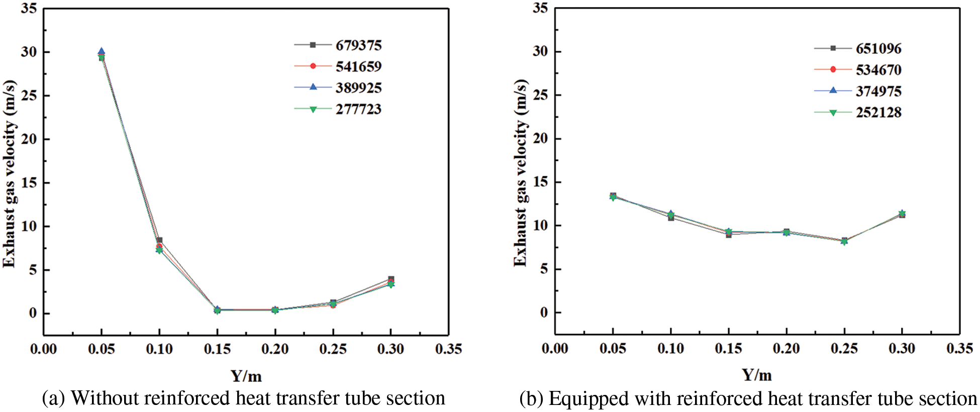
Figure 5: Exhaust gas velocity with different mesh number
Fig. 5 shows that the variation range of the exhaust gas velocity is small at the same measurement point and for different mesh numbers. Fig. 5a depicts that there are small velocity fluctuations as the mesh numbers are 277723 and 389925, Y are 0.05, 0.10, and 0.30 m. From Fig. 5b, we can see that with an increase in the mesh number, the trend of the exhaust gas velocity is similar, which can demonstrate the accuracy of the simulation. Finally, the mesh numbers of the exhaust-gas heat exchanger with and the without reinforced heat transfer tube section taken into simulation are 541659 and 534670.
3.2.4 Mesh Division and Flow Field
The gas flow simulation is carried out to provide reference information to the structural design of the exhaust-gas heat exchanger. The mesh between the exhaust-gas heat exchanger with reinforced heat transfer tube section and the without is shown in Fig. 6. The round hole at the front of the mesh is the reinforced heat transfer tube section. Both the exhaust-gas heat exchanger box and the fin and tube section are set up as wall surfaces.
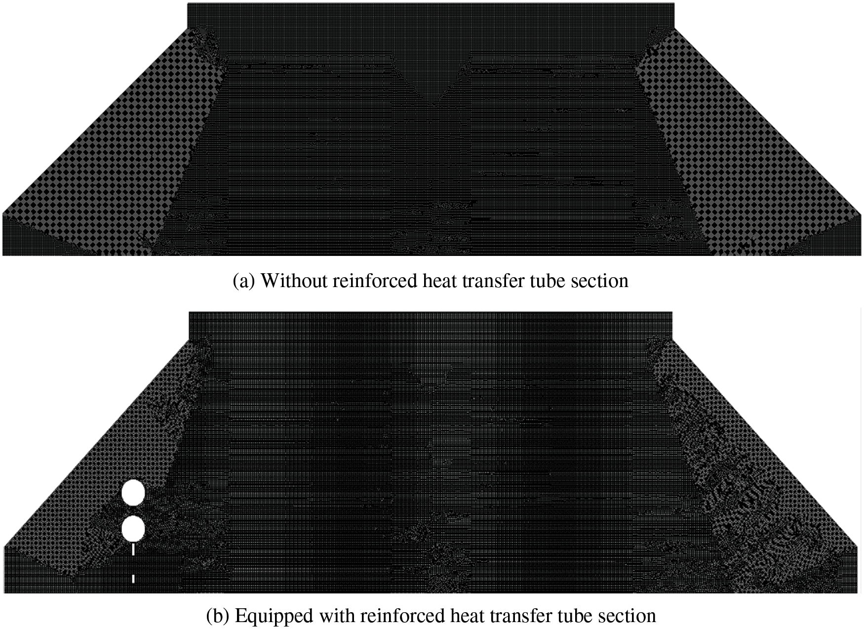
Figure 6: The mesh of the heat exchanger
Fig. 7 shows that distribution of internal flow field of the heat exchanger. From Fig. 7a we can see that some of the exhaust gas is diffused to flow into the outer fins due to the resistance of the unequal-spaced fins, but the range of exhaust flow is small. Fig. 7b depicts that the exhaust gas is disturbed by the reinforced heat transfer tube section, and exhaust gas velocity is slowed down. Due to the resistance of the first set of unequal-spaced fins, some of the exhaust gas is diffused to flow into the outer fins and enters the fin and tube section more evenly. A large number of fins are involved in heat transfer, and the dead zone vortex area between fins is small. Then the exhaust gas is thoroughly mixed in the mixing zone between the two sets of fins, which improves the uniformity of the flow field distribution. The exhaust gas is further diffused by the second set of unequal-spaced fins after passing through the mixing zone, which will lead to the heat transfer of the second set of fins as more uniform, and more fins will participate in the heat transfer. In summary, the exhaust gas flow field at the middle and outer fins of the heat exchanger is more evenly distributed, and the heat exchanger structure is reasonable.
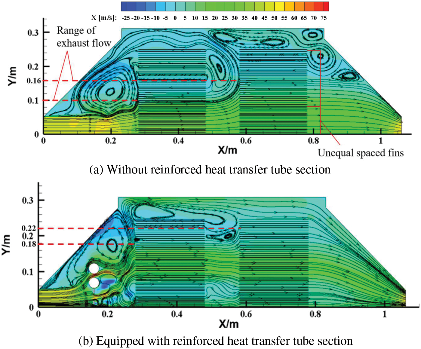
Figure 7: Distribution of internal flow field of the heat exchanger
3.3 Structure Design of Heat Exchanger
Based on the above results of the flow field in fins, an exhaust-gas heat exchanger combining unequally spaced fins and a reinforced heat transfer tube section. The 3D structure of the heat exchanger is shown in Fig. 8. The inlet area and the windward area of the exhaust-gas heat exchanger are small, and the structure of the heat exchanger is reformed to make the exhaust gas diffusion more evenly. The exhaust gas first passes through the reinforced heat transfer tube section for scrambling, then sweeps through the first row of unequally spaced fins, enhancing the heat transfer due to the resistance effect on the exhaust gas. The exhaust gas then enters the intermediate mixing zone for fluid heat mixing, enhancing the heat transfer in the rear part of the fins as well. These are four characters in the exhaust-gas heat exchanger:
(1) A reinforced tube unit with a 225 mm peripheral dimension is added at 115 mm in front of the fin and tube heat exchanger unit, which can disturb the flow of exhaust gas and heat the water from four distributors uniformly.
(2) The fin part adopts an unequal spacing arrangement to increase the resistance of the middle fins to the exhaust gas and increase the exhaust gas flow rate on the outer fins of the heat exchanger.
(3) A mixing zone is set up between the fin groups to enhance the heat transfer effect of the rear half of the fins.
(4) The cold fluid in the tube bundle is divided into four routes, which can enhance the uniformity of heat transfer.

Figure 8: 3D structure of the heat exchanger
4 Building the Experimental System Bench and Analysis of Experimental Results
4.1 Systematic Experimental Loop Construction
Table 4 shows the exhaust-gas heat exchanger model specifications. The final proposed exhaust-gas heat exchanger has a fin height of 0.6 m, a device as a whole length of 1.06 m, and a mass of 80 kg. Fig. 9 depicts the flow direction of exhaust gas as well as that of water of the exhaust-gas heat exchanger at the experimental site. Fig. 10 shows an exhaust gas heat recovery system and seawater desalination system, which are added to the marine diesel engine test device. The circulating water flow rate of the exhaust gas heat recovery system can be controlled by the electric butterfly valve, which is from 1 to 3 m³/h. The exhaust gas heat is transferred to the exhaust gas heat recovery system’s circulating water by the exhaust-gas heat exchanger. When the circulating water temperature of the exhaust gas heat recovery system meets the requirements of the seawater desalination membrane module, the seawater desalination circulating water loop starts to operate. The heat is transferred to the seawater desalination membrane device through a seawater heat exchanger, and then the freshwater is produced and stored in the tank. The temperature measuring points are set up at F point, the exhaust gas after heat recovery, at g and h points, and the inlet and outlet water temperature of the exhaust-gas heat exchanger, respectively.

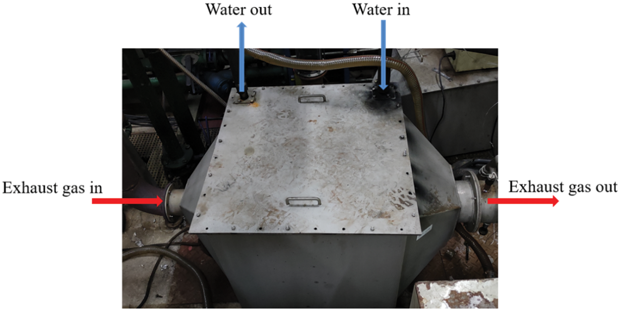
Figure 9: Exhaust-gas heat exchanger at the experimental site
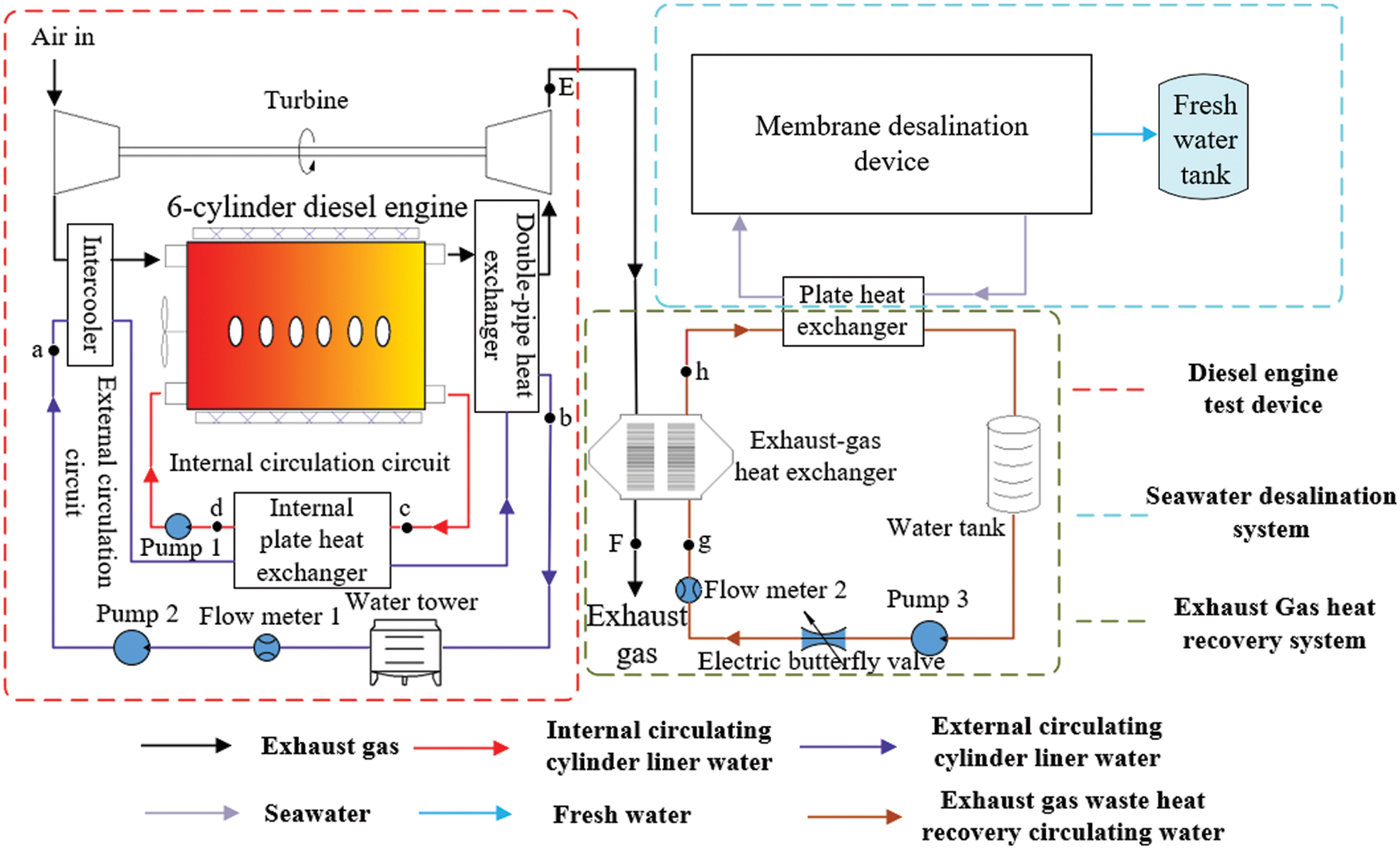
Figure 10: Circulation loop diagram of the improved experimental bench system
4.2 Experimental Results and Discussion
4.2.1 Exhaust Gas Temperature and Water Temperature in the Exchanger at Different Loads
The exhaust gas temperature and circulating water temperature of the exhaust-gas heat exchanger were monitored at 25%–100% marine diesel engine loads with the circulating water flow rate of 1–3 m3/h. The temperature difference between exhaust gas and that of circulating water through the exhaust-gas heat exchanger are shown in Fig. 11. As the marine diesel engine load increases, the temperature difference between the inlet and outlet circulating water and exhaust gas through the exhaust-gas heat exchanger increase linearly. With the circulating water flow rate reducing and the marine diesel engine load ranging from 60% to 100%, the increase of the exhaust gas temperature difference becomes smaller. This indicates that the waste heat recovery efficiency will be reduced at high diesel engine load, which will be more obvious as the circulating water flow rate is reduced. When the circulating water flow rate of the heat exchanger is 1 m³/h and the marine diesel engine load is at 100%, the maximum water temperature difference is about 75°C, and the exhaust gas temperature difference is about 196°C. When the circulating water flow rate of the heat exchanger is 3 m³/h, the water temperature difference is about 35°C, and the exhaust gas temperature difference is about 247°C. If the circulating water flow rate of the exhaust-gas heat exchanger increases more, the exhaust gas temperature difference becomes more significant, and the water temperature difference becomes smaller.
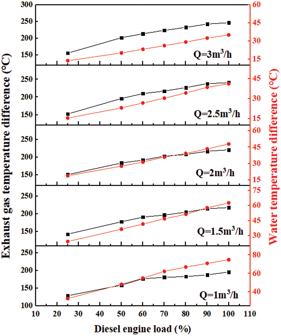
Figure 11: Temperature difference of exhaust gas and water in heat exchanger
4.2.2 Heat Difference between the Exhaust Gas Side and Water Side
According to the average specific heat capacity of the exhaust gas, the recovered heat of the exhaust gas,
where
Fig. 12 depicts the comparison of heat difference between
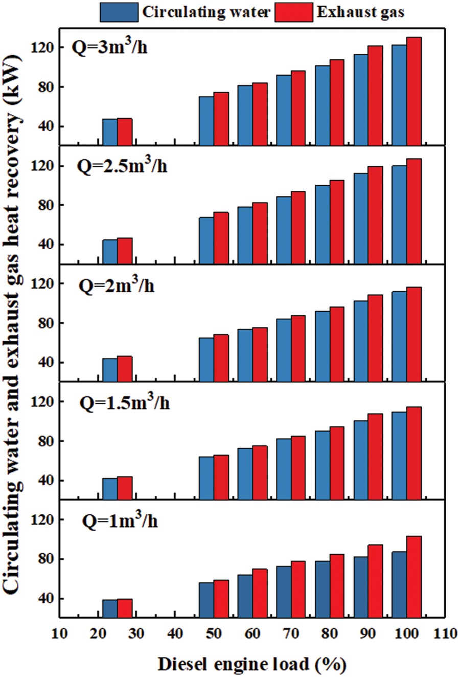
Figure 12: Comparison of heat difference between the exhaust gas and water sides
As a load of the marine diesel engine increases, the heat of the circulating water and the exhaust gas increases, and the heat of the circulating water side is a little bit less than the exhaust gas side. This means there is a heat loss in the exhaust-gas heat exchanger.
When the circulating water flow rate is 1 m³/h, the proportion of heat difference between the circulating water side and exhaust gas side is large. This means that the heat loss of the exhaust gas side is higher when the circulating water flow rate is small. When the circulating water flow rate is 3 m³/h, the proportion of heat difference between the circulating water side and exhaust gas side becomes small. This means that the heat loss rate of the exhaust gas side is low when the circulating water flow rate is high. Based on the study of these contents, it can provide a reference for improving the heat recovery rate of the exhaust-gas heat exchanger.
The relationship between the heat difference rate

Figure 13: Comparison of the heat difference and the circulating water flow rate
4.2.3 Heat Recovery Efficiency of the Exhaust-Gas Heat Exchanger
The heat recovery efficiency, η, of the exhaust-gas heat exchanger can be obtained by considering the heat recovered from the water to the recoverable heat from the exhaust gas, and can be written as:
The heat recovery efficiency of the exhaust-gas heat exchanger is shown in Fig. 14. Due to the increase in the water flow rates, the heat recovery efficiency increases at the same operating condition. As the diesel engine load increases, the heat recovery efficiency decreases at the same water flow rate. The heat recovery efficiency is low as the circulating water flow rate is 1 m3/h, and there is a big difference when the water flow rate is 1.5–3 m3/h, which shows that the heat recovery efficiency decreases obviously under low water flow rate. Therefore, the low water flow rate for heat recovery should be avoided at a high diesel engine load. When the engine load is constant and the circulating water flow rate is 1.5–3 m3/h, the heat recovery efficiency is high and increases slowly, which indicates that the heat recovery efficiency is efficient and stable at a high water flow rate. The highest heat recovery efficiency can reach 85.9% at 25% load, and the water flow rate of 3 m3/h, and the lowest heat recovery efficiency is 50.8% at 100% load and the water flow rate of 1 m3/h, respectively. The analysis results indicate that a smaller volume flow rate and higher diesel engine load have a detrimental effect on the heat recovery efficiency.
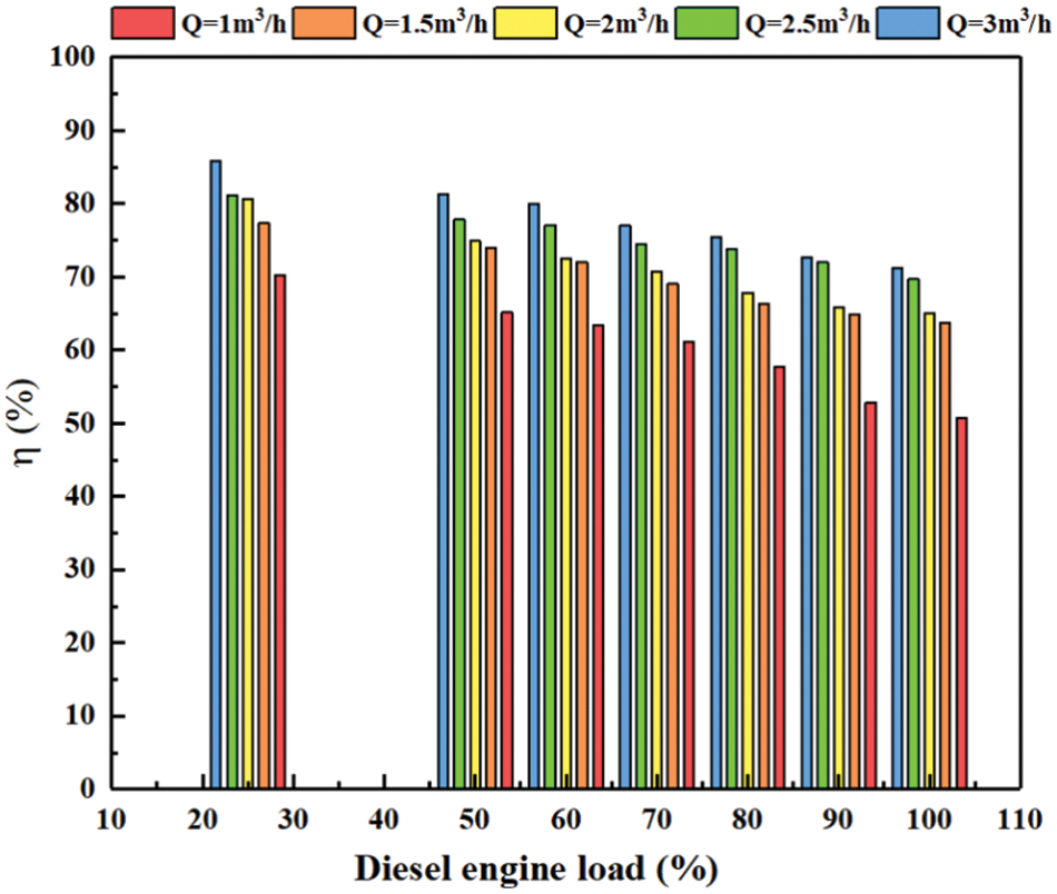
Figure 14: Heat recovery efficiency of the exhaust-gas heat exchanger
To meet the requirements of seawater desalination, the outlet water temperature of the exhaust-gas heat exchanger needs to be higher than 55°C and lower than 85°C. In all experimental cases, the inlet water temperature of the exhaust-gas heat exchanger is 20°C. In order to recover more heat from the exhaust gas and match the requirements of seawater desalination, a coupling analysis is carried out for the water flow rate and the outlet water temperature of the exhaust-gas heat exchanger with different engine loads, as is shown in Fig. 15.

Figure 15: Outlet water temperature at different loads
In order to improve the heat recovery efficiency of the exhaust-gas heat exchanger, it can be achieved by changing the water flow rate. Fig. 15 depicts that the outlet water temperature decreases with the increase of the water flow rate at the same load. As the diesel engine load increases, the outlet water temperature increases at the same water flow rate. By changing the water flow rate of the exhaust-gas heat exchanger, the outlet water temperature can reach 55°C–85°C at different engine loads. The blue and red dotted lines represent the lower and upper limits of the water temperature required by the membrane desalination device: 55°C, and 85°C, respectively. In the region between the blue and red dotted lines, the exhaust-gas heat exchanger’s outlet water temperature can meet the seawater desalination device requirements and the heat recovery is higher than 38 kW. The details are as follows: when the marine diesel engine runs at 25% load, and the water flow rate is 1 m³/h, the heat exchanger’s outlet water temperature and heat recovery efficiency are 56.1°C and 70.2%. As the marine diesel engine runs at 50% and 60% loads and the water flow rate is 1.5 m³/h, the heat exchanger’s outlet water temperature and heat recovery efficiency are 56.6°C, 61.7°C, and 73.9%, 72%, respectively. When the marine diesel engine runs at 70% load and the water flow rate is 2 m³/h, the heat exchanger’s outlet water temperature and heat recovery efficiency are 56°C and 71%. As the marine diesel engine runs at 80% and 90% loads and the water flow rate of the heat exchanger is 2.5 m³/h, the heat exchanger’s outlet water temperature and heat recovery efficiency are 55.8°C, 58.5°C, and 73.8%, 72%, respectively. When the marine diesel engine runs at 100% load and the water flow rate of the heat exchanger is 3 m³/h, the heat exchanger’s outlet water temperature, and heat recovery efficiency are 56.1°C and 71.3%. With the diesel engine load increasing, the exhaust gas’s heat recovery ranges from 38.6 to 122.9 kW. The water flow rate can be reduced in the regions between the blue and red dotted lines to obtain a higher outlet water temperature. Thus, by changing the water flow rate of the exhaust-gas heat exchanger, the outlet water temperature of 55–85°C can be obtained, and the heat recovery from exhaust gas in all cases is greater than 38 kW. This study can meet the requirements of the seawater desalination membrane module, and the heat recovery efficiency of the exhaust-gas heat exchanger is greater than 70%, which is a high heat transfer efficiency for exhaust-gas heat exchangers.
In this paper, a new heat exchanger was designed for the exhaust gas heat recovery of small and medium-sized marine diesel engines. The exhaust gas heat recovery experiments for the marine diesel engine at 25%–100% load and rated speed were conducted to verify the heat transfer effect. The following conclusions are drawn:
(1) According to the characteristics of the small windward surface and high exhaust gas flow rate in the heat exchanger, a compact exhaust-gas heat exchanger with the fin-tube and a reinforced heat transfer tube section was designed. The internal flow fields of the exhaust-gas heat exchanger with reinforced heat transfer tube section and the without were analyzed by CFD (fluent) software, and the rationality of the heat exchanger structure was verified.
(2) From the gas flow simulation, the exhaust gas is disturbed by the reinforced heat transfer tube section, and exhaust gas velocity is slowed down. Due to the resistance of the unequal spaced fins, some of the exhaust gas is diffused to flow into the outer fins and enters the fin and tube section more evenly. The exhaust gas is fully mixed in the mixing zone between the two sets of fins, and the dead zone vortex area between fins is small.
(3) The difference between the heat absorption by the water in the exhaust-gas heat exchanger and the heat reduction of exhaust gas is within 6.5%, which ensures the accuracy of the experiment.
(4) The outlet water temperature of the exhaust-gas heat exchanger can meet the requirements of the membrane desalination device, and the heat recovered from the exhaust gas ranges from 38.6 to 122.9 kW. With the cooling water flow rate adjusted, the heat recovery efficiency of the exhaust-gas heat exchanger is greater than 70%.
Acknowledgement: The author sincerely thanked the National Key Research and Development Program of China and the Postgraduate Research & Practice Innovation Program of Jiangsu Province, China, for funding, mainly for research on the exhaust-gas heat exchangers for small and medium-sized marine diesel engines.
Funding Statement: This work was supported by the National Key Research and Development Program of China [Grant No. 2017YFE0116100] and the Postgraduate Research & Practice Innovation Program of Jiangsu Province, China [Grant No. KYCX20_2821].
Conflicts of Interest: The authors declare that they have no conflicts of interest to report regarding the present study.
References
1. Badami, M., Mura, M., Campanile, P., Anzioso, F. (2008). Design and performance evaluation of an innovative small-scale combined cycle cogeneration system. Energy, 33(8), 1264–1276. DOI 10.1016/j.energy.2008.03.001. [Google Scholar] [CrossRef]
2. Wang, T. Y., Zhang, Y. J., Peng, Z. J., Shu, G. Q. (2011). A review of researches on thermal exhaust heat recovery with Rankine cycle. Renewable and Sustainable Energy Reviews, 15(6), 2862–2871. DOI 10.1016/j.rser.2011.03.015. [Google Scholar] [CrossRef]
3. Willems, F., Kupper, F., Cloudt, R. (2012). Integrated energy & emission management for heavy-duty diesel engines with waste heat recovery system. IFAC Proceedings Volumes, 45(30), 270–277. DOI 10.3182/20121023-3-FR-4025.00055. [Google Scholar] [CrossRef]
4. Yu, C., Chau, K. T. (2009). Thermoelectric automotive waste heat energy recovery using maximum power point tracking. Energy Conversion and Management, 50(6), 1506–1512. DOI 10.1016/j.enconman.2009.02.015. [Google Scholar] [CrossRef]
5. Dolz, V., Novella, R., García, A., Sánchez, J. (2011). HD diesel engine equipped with a bottoming Rankine cycle as a waste heat recovery system. Part 1: Study and analysis of the waste heat energy. Applied Thermal Engineering, 36, 269–278. DOI 10.1016/j.applthermaleng.2011.10.025. [Google Scholar] [CrossRef]
6. Khani, M. R., Pour, E. B., Rashnoo, S., Tu, X., Ghobadian, B. et al. (2020). Real diesel engine exhaust emission control: indirect non-thermal plasma and comparison to direct plasma for NOx, THC, CO, and CO2. Journal of Environmental Health Science & Engineering, 18(2), 743–754. [Google Scholar]
7. Chung, S., Seo, C. D., Choi, J. H., Chung, J. (2014). Evaluation method of membrane performance in membrane distillation process for seawater desalination. Environmental Technology, 35(17), 2147–2152. [Google Scholar]
8. Sun, A. C., Kosar, W., Zhang, Y. F., Feng, X. S. (2014). Vacuum membrane distillation for desalination of water using hollow fiber membranes. Journal of Membrane Science, 455, 131–142. [Google Scholar]
9. Qtaishat, M. R., Banat, F. (2013). Desalination by solar powered membrane distillation systems. Desalination, 308, 186–197. [Google Scholar]
10. Mohamed, K. (2011). Membranes and theoretical modeling of membrane distillation: a review. Advances in Colloid and Interface Science, 164(1–2), 56–88. [Google Scholar]
11. Singh, D., Sirkar, K. K. (2014). High temperature direct contact membrane distillation based desalination using PTFE hollow fibers. Chemical Engineering Science, 116, 824–833. [Google Scholar]
12. Panchal, H., Patel, V., Prajapati, V., Patel, D., Patel, H. et al. (2017). Experimental analysis of diesel engine exhaust gas coupled with water desalination for improved fresh water production. International Journal of Ambient Energy, 38(6), 567–570. [Google Scholar]
13. Lu, Z. S., Wang, R. Z. (2016). Experimental performance study of sorption refrigerators driven by waste gases from fishing vessels diesel engine. Applied Energy, 174, 224–231. [Google Scholar]
14. Hou, S. Y., Wu, Y. D., Zhou, Y. D., Yu, L. J. (2017). Performance analysis of the combined supercritical CO2 recompression and regenerative cycle used in waste heat recovery of marine gas turbine. Energy Conversion and Management, 151, 73–85. [Google Scholar]
15. Wang, X., Shu, G. Q., Tian, H., Liu, P., Jing, D. Z. et al. (2017). Dynamic analysis of the dual-loop Organic Rankine Cycle for waste heat recovery of a natural gas engine. Energy Conversion and Management, 148, 724–736. [Google Scholar]
16. He, W., Wang, S. X., Zhang, X., Li, Y. Z., Lu, C. et al. (2015). Optimization design method of thermoelectric generator based on exhaust gas parameters for recovery of engine waste heat. Energy, 91, 1–9. DOI 10.1016/j.energy.2015.08.022. [Google Scholar] [CrossRef]
17. Choi, Y., Negash, A., Kim, T. Y. (2019). Waste heat recovery of diesel engine using porous medium-assisted thermoelectric generator equipped with customized thermoelectric modules. Energy Conversion and Management, 197, 111902. DOI 10.1016/j.enconman.2019.111902. [Google Scholar] [CrossRef]
18. Ji, D. X., Wei, Z. B., Mazzoni, S., Mengarelli, M., Rajoo, S. et al. (2018). Thermoelectric generation for waste heat recovery: Application of a system level design optimization approach via Taguchi method. Energy Conversion and Management, 172, 507–516. DOI 10.1016/j.enconman.2018.06.016. [Google Scholar] [CrossRef]
19. Aghaali, H., Ångström, H. E. (2015). A review of turbocompounding as a waste heat recovery system for internal combustion engines. Renewable and Sustainable Energy Reviews, 49, 813–824. DOI 10.1016/j.rser.2015.04.144. [Google Scholar] [CrossRef]
20. Yerne, Y. U., Bhusnoor, S. S. (2019). Theoretical thermal analysis of heat recovery by two phases closed Thermosyphon from engine exhaust. Heat and Mass Transfer, 55(11), 3211–3221. DOI 10.1007/s00231-019-02641-x. [Google Scholar] [CrossRef]
21. Shafieian, A., Khiadani, M. (2020). A multipurpose desalination, cooling, and air-conditioning system powered by waste heat recovery from diesel exhaust fumes and cooling water. Case Studies in Thermal Engineering, 21, 100702. DOI 10.1016/j.csite.2020.100702. [Google Scholar] [CrossRef]
22. Liang, Y. C., Bian, X. Y., Qian, W. W., Pan, M. Z., Ban, Z. B. et al. (2019). Theoretical analysis of a regenerative supercritical carbon dioxide Brayton cycle/organic Rankine cycle dual loop for waste heat recovery of a diesel/natural gas dual-fuel engine. Energy Conversion and Management, 197, 111845. DOI 10.1016/j.enconman.2019.111845. [Google Scholar] [CrossRef]
23. Xu, B., Rathod, D., Kulkarni, S., Yebi, A., Filipi, Z. et al. (2017). Transient dynamic modeling and validation of an organic Rankine cycle waste heat recovery system for heavy duty diesel engine applications. Applied Energy, 205, 260–279. DOI 10.1016/j.apenergy.2017.07.038. [Google Scholar] [CrossRef]
24. Li, K. L., Hou, D. Y., Fu, C. C., Wang, K., Wang, J. (2019). Fabrication of PVDF nanofibrous hydrophobic composite membranes reinforced with fabric substrates via electrospinning for membrane distillation desalination. Journal of Environmental Sciences, 75, 277–288. DOI 10.1016/j.jes.2018.04.002. [Google Scholar] [CrossRef]
25. Sun, J. M., Zhang, C. D., Zhou, Z. Y. (2012). Research of energy saving control for central air-conditioning based on adaptive fuzzy PID method. Applied Mechanics and Materials, 1975, 4286–4291. DOI 10.4028/www.scientific.net/AMM.204-208.4286. [Google Scholar] [CrossRef]
26. Lim, T., Lee, C. K. (2018). Thermodynamic analysis of ORC to recover waste heat of jacket cooling water in diesel engine. Journal of Fisheries and Marine Sciences Education, 30(3), 1032–1039. DOI 10.13000/JFMSE.2018.06.30.3.1032. [Google Scholar] [CrossRef]
27. Jiang, R. H., Qin, F. G. F., Yang, X. X., Huang, S. M., Chen, B. M. et al. (2018). Performance analysis of a liquid absorption dehumidifier driven by jacket-cooling water of a diesel engine in a CCHP system. Energy & Buildings, 163, 70–78. DOI 10.1016/j.enbuild.2017.12.030. [Google Scholar] [CrossRef]
28. Zhang, H. G., Wang, E. H., Fan, B. Y. (2013). Heat transfer analysis of a finned-tube evaporator for engine exhaust heat recovery. Energy Conversion and Management, 65, 438–447. DOI 10.1016/j.enconman.2012.09.017. [Google Scholar] [CrossRef]
29. Saman, W. Y., Alizadeh, S. (2002). An experimental study of a cross-flow type plate heat exchanger for dehumidification/cooling. Solar Energy, 73(1), 59–71. DOI 10.1016/S0038-092X(01)00078-0. [Google Scholar] [CrossRef]
30. Choi, J. M., Kim, Y., Lee, M., Kim, Y. (2009). Air side heat transfer coefficients of discrete plate finned-tube heat exchangers with large fin pitch. Applied Thermal Engineering, 30(2), 174–180. DOI 10.1016/j.applthermaleng.2009.08.001. [Google Scholar] [CrossRef]
31. Shakir, A. M., Mohammed, A. K., Hasan, M. I. (2011). Numerical investigation of counter flow microchannel heat exchanger with slip flow heat transfer. International Journal of Thermal Sciences, 50(11), 2132–2140. DOI 10.1016/j.ijthermalsci.2011.05.021. [Google Scholar] [CrossRef]
Cite This Article
 Copyright © 2023 The Author(s). Published by Tech Science Press.
This work is licensed under a Creative Commons Attribution 4.0 International License , which permits unrestricted use, distribution, and reproduction in any medium, provided the original work is properly cited.
 Downloads
 Citation Tools