
 Submit a Paper
 Propose a Special lssue
 Open Access
ARTICLE

Operation Control Method of Relay Protection in Flexible DC Distribution Network Compatible with Distributed Power Supply
School of Electric Power Engineering, South China University of Technology, Guangzhou, 510641, China
* Corresponding Author: Zihan Qi. Email:
Energy Engineering 2023, 120(11), 2547-2563. https://doi.org/10.32604/ee.2023.027045
Received 11 October 2022; Accepted 17 May 2023; Issue published 31 October 2023
 View Full Text
 Download PDF
Abstract
A novel operation control method for relay protection in flexible DC distribution networks with distributed power supply is proposed to address the issue of inaccurate fault location during relay protection, leading to poor performance. The method combines a fault-tolerant fault location method based on long-term and short-term memory networks to accurately locate the fault section. Then, an operation control method for relay protection based on adaptive weight and whale optimization algorithm (WOA) is used to construct an objective function considering the shortest relay protection action time and the smallest impulse current. The adaptive weight and WOA are employed to obtain the optimal strategy for relay protection operation control, reducing the action time and impulse current. Experimental results demonstrate the effectiveness of the proposed method in accurately locating faults and improving relay protection performance. The longest operation time is reduced by 4.7023 s, and the maximum impulse current is limited to 0.3 A, effectively controlling the impact of large impulse currents and enhancing control efficiency.Keywords
In recent years, with the development of the power industry and the requirements of environmental protection, the sustainable utilization of energy and environmental protection have become strategic issues of global concern. Using new energy to generate electricity has also become the focus of the power industry research in various countries.
At present, most countries in the world primarily rely on non-renewable resources for power generation, such as coal, natural gas, and oil. However, there is a global consensus that the depletion of these resources is becoming a pressing issue. According to investigations conducted by relevant international authorities in the early 21st century, it was found that the recoverable quantities of oil, natural gas, and coal are estimated to last for approximately 39.3, 61, and 227 years, respectively. Additionally, the extensive use of these non-renewable resources has resulted in significant environmental pollution [1].
In the quest for new sources of energy, there is a growing focus on the utilization of renewable and clean energy, such as wind energy, solar energy, hydropower, and tidal energy. These energy sources are not only renewable but also have minimal carbon dioxide emissions. They are considered the optimal choice for fostering a low-carbon economy and achieving sustainable development [2]. China, being a large developing country, heavily relies on energy for its development. While China does possess vast territory and abundant resources, it still depends on imports for many of its energy needs. Consequently, increasing the utilization of clean resources and reducing reliance on imported energy has become a key component of China’s energy strategy.
Hamidan et al. proposed using distributed generators (DG) and battery energy storage systems (BESS) to enhance the reliability of distribution networks. Their objective functions, based on a decomposition-based multi-objective evolutionary algorithm, aimed to minimize ENS, reduce load loss and cost, and decrease voltage drop in the network [3]. Liu et al. [4] developed an intelligent management and control system that analyzed four key relay protection systems: OCS, protection and information system, wave recording system, and traveling wave system. This system improved power grid coordination control and emergency response capability. Popovic et al. utilized fuzzy sets, fuzzy mixed integer linear programming, and risk analysis to generate network automation plans. They assessed risks using the maximum expected monetary value standard and selected the most effective automation plan to handle load and power generation uncertainties and variability [5]. Motepe et al. [6] conducted a comparative study on load forecasting performance using ML, DL, ANFIS, and OP-ELM technologies. They found that incorporating temperature generally improved the performance of ML and DL models. Wang et al. designed a greedy algorithm to optimize the positioning of feeder switches for efficient energy usage. If a branch of the distribution network fails, the corresponding sectionalized feeder switch will trip immediately to eliminate the fault before restoring the network, ensuring fault-free operation [7]. However, none of these methods addressed fault location research, leading to inadequate fault location effectiveness and reduced relay protection performance.
Distributed generation(DG), it is a small modular power supply system arranged near users in a decentralized manner with a power generation power of tens of kW to tens of MW environment compatible independent power supply [8]. The combination of large power grid and distributed generation is recognized by many energy and power experts in the world as the main way to save investment, reduce energy consumption and improve the reliability and flexibility of power system.
In addition, the continuous development and progress of fully controlled power electronic devices have made the flexible DC distribution technology of voltage source converters more sophisticated. This advancement has also highlighted the economic advantages, thereby promoting the development of distributed energy. The global focus on environmental pollution and energy scarcity has further amplified this trend. Common sources of distributed energy include wind power generation and fuel cells. The electric energy generated by wind turbines needs to be connected to the AC power grid through DC-AC and AC-DC converters. However, if the DC power generated by photovoltaic cells is connected directly to the DC network, the need for an AC-DC link can be eliminated, thereby reducing commutation losses [9]. Conversely, when the DC power needs to be connected to the AC network, it requires a DC-AC link. With the increasing use of mobile phones and computers, the demand for electricity has significantly changed, leading to a growing reliance on DC power. Implementing a flexible power supply mode through a DC distribution network can greatly reduce the need for DC-AC links and minimize commutation losses. However, the instability of distributed power can directly impact the power quality of the flexible DC distribution network. Currently, common relay protection devices like circuit breakers are employed to safeguard the power quality of the distribution network against abnormalities.
Based on the aforementioned information, this paper focuses on studying the operation control method for relay protection in a flexible DC distribution network that is compatible with distributed power. The aim is to provide valuable technological insights for the operation control of relay protection in such networks. Experimental results indicate that the maximum impulse current under the control of the relay protection device in this study is 0.3 A, which is relatively small and effectively mitigates the impact of large impulse currents on the distribution network. Furthermore, the longest operation time is reduced by 4.7023 s, indicating an improvement in control efficiency.
2 Operation Control Method for Relay Protection in Flexible DC Distribution Network
2.1 Fault-Tolerant Fault Location Method of Flexible DC Distribution Network Based on Long-Term and Short-Term Memory Network
The relay protection device plays a crucial role in accurately identifying and distinguishing between normal operation and faults within the protected section. It is essential to locate the fault section accurately, whether it is within or outside the protection area [10]. This paper proposes a fault-tolerant fault location method for flexible DC distribution networks based on long-term and short-term memory networks, aiming to precisely locate faults in the distribution network.
The long-term and short-term memory network (LSTM) can process long-term sequences and effectively extract sequence features [11]. Using its characteristics, this paper proposes a fault-tolerant fault location method of flexible DC distribution network based on long-term and short-term memory network. This method realizes fault-tolerant fault location by constructing LSTM network to identify the characteristics of current and voltage sequences at both ends of each section and combining logic gate judgment.
2.1.1 Framework of Fault Location Method for Distribution Network
The fault-tolerant fault location method for flexible DC distribution networks, which is based on long-term and short-term memory networks, consists of two main steps: local training and testing, and online fault location. The detailed process is illustrated in Figs. 1 and 2.
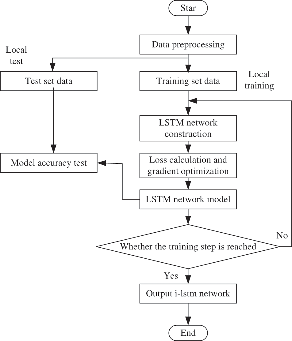
Figure 1: Local training test
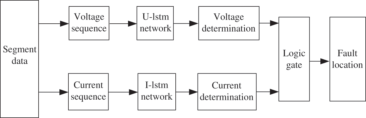
Figure 2: Online fault location
By conducting local training and testing, a robust LSTM network is developed. When a failure occurs in the flexible DC distribution network with distributed power supply, real-time electric energy data is collected and inputted into the pre-trained network. By incorporating logical gate processing and analysis, the online fault location of the distribution network is achieved [12].
Fig. 1 illustrates the specific steps for network training of local training current sequence LSTM (I-LSTM), while the network training methods for voltage sequence LSTM (U-LSTM) are similar. The implementation steps are as follows:
(1) Divide the distribution network into multiple double-ended non-branching sections and collect the double-ended current and voltage time series before and after the fault, defining the head and end of each section.
(2) Expand the existing sampling data set, preprocess the data, encode the labels, and split it into a training set and a test set.
(3) Construct LSTM networks for both the voltage sequence and current sequence.
(4) Calculate the loss value in a single step and optimize it through gradient-based methods. Adjust the network parameters based on the learning direction provided by the optimization, representing the learning and training process of the model.
(5) Training of the LSTM network is stopped and the final network is obtained when the set number of steps is reached. If the set step size is not yet reached, the network parameters are adjusted and step (4) is repeated to continue training the network.
(6) Online fault location.
The steps of online fault location are:
(1) In case of failure, load the real-time sampling data at the head and end of each section into the trained LSTM network, and determine the output voltage and current.
(2) Build logic gates, combine voltage determination with current determination, and divide all sections into fault section, suspicious section and normal section.
(3) Determine the status of each section of flexible DC distribution network compatible with distributed power supply.
2.1.2 Current Sequence and Voltage Sequence of the Section
In a distribution network with distributed power supply, it is crucial to designate a power supply as the system power supply. The active distribution network’s lines are divided into multiple double-ended non-branching sections. The node that is closer to the system power supply is defined as the section head end, while the remaining nodes serve as the section end [13]. This structural standard provides a sequential configuration for the network.
The voltage sequence
where, subscripts
In this paper, the required sequence input is formed by selecting three-phase current and voltage sampling sequences (referred to as electric energy data) measured by one cycle line before and after the fault [14].
In order to better extract the characteristics of electric energy data, it is necessary to preprocess the data. The data in the voltage sequence and current sequence collected by the section are root mean square (RMS) per unit value, and the sequence and label are processed as follows:
(1) Data normalization
The data of voltage series and current series are normalized. Normalization can accurately reflect the relationship between data of different dimensions, prevent small data from being flooded by big data, and effectively improve the accuracy and convergence speed of the model [15]. The min-max method is used for data normalization, and the specific method is shown in Eq. (1).
where,
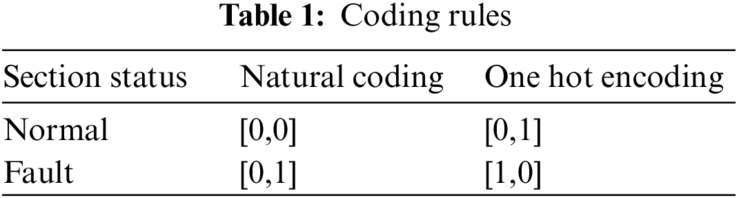
2.1.4 Label’s One-Hot Processing
One-Hot coding is also known as one-bit effective coding. The encoding method is to use
Using One-Hot coding can solve the problem that the classifier is difficult to deal with attribute data, and it also plays a role in expanding features to a certain extent. The coding rules are shown in Table 1.
2.1.5 Fault Location Model Combined with Logic Gates
In this paper, we construct an LSTM network through supervised training of voltage sequences and current sequences separately. The fault location model consists of two LSTM networks and a logic gate [16]. Specifically, the LSTM network is composed of LSTM blocks, which train the weights and bias terms over multiple time steps.
After the fault occurs, the
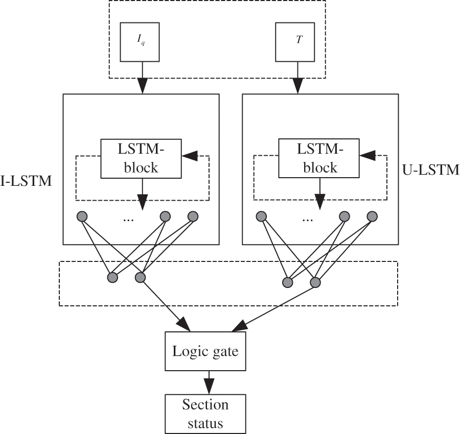
Figure 3: Fault location model combined with logic gate
The basic corresponding rules of logic gates are shown in Table 2.
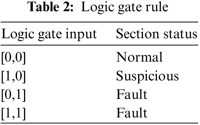
The section status in the distribution network is classified into three types: normal section, suspicious section, and fault section. This classification aims to enhance the method’s fault tolerance rate and provide directional suggestions.
To prevent misjudgment of the voltage sequence by the neural network, even when the input is [0,1], it still indicates a section fault. This means that the judgment of the U-LSTM network serves as a supporting role.
Based on logical gate rules, if the input current sequence is partially missing or abnormal, and the I-LSTM is determined to be invalid while the U-LSTM is determined to be successful, the section can be classified as suspicious.Overall, these measures contribute to improving fault tolerance and providing more accurate indications for the sections in the distribution network.
2.2 The Operation Control Method for Relay Protection of Distribution Network Based on Adaptive Weight and Whale Optimization Algorithm
Combined with the fault section located in Section 2.1, it can start the relay protection device in this section, and use the operation control method for relay protection of distribution network based on adaptive weight and whale optimization algorithm to realize fault control.
The action characteristic equation of the conventional inverse time overcurrent protection of the relay is:
With the continuous advancement of relay protection technology, there has been a growing trend towards utilizing adaptive relay protection devices in the control of distribution networks. Intelligent protection technology based on expert systems and neural networks has been proposed and successfully implemented in certain regional power grids. However, the research focus of expert systems or neural networks mainly centers around fault analysis and calculations, with relatively limited emphasis on optimizing relay setting values. In comparison to traditional calculation methods, there have been no substantial changes, and manual intervention is still required [17]. For theinverse time limit overcurrent relay, its setting optimization is mainly carried out for the two parameters of time setting coefficient
where,
The evaluation of a set of protection schemes should be based on the coordinated actions of relays throughout the distribution network. Typically, it is required that when a fault occurs, the relay within the power grid can promptly and accurately detect the fault location and isolate it within the smallest possible range in the shortest amount of time [19]. Therefore, optimizing the setting of relay protection can be viewed as achieving mutual coordination among relays in the distribution network. In order to achieve coordination, the objective is to minimize the weighted sum of the relay action times. For instance, if only an inverse time overcurrent relay is installed in a power grid, the objective function of relay protection operation control can be expressed as minimizing the shortest relay protection action time:
where,
The objective function of all relays in the whole distribution network that have cooperation relationship with each other is:
where, although the fault current
The cooperation between relays and other hardware factors can be described by constraints.
Eq. (7) indicates that the time setting coefficient can only be taken within the allowable range of the relay element itself; Eq. (8) indicates that the impulse current of the relay should also be taken within an allowable range.
In addition, the distribution network itself also has certain requirements for relay protection system. Therefore, the constraints that Eq. (6) also needs to meet are:
wherein, Eq. (9) ensures the mutual cooperation between relays through a time differential
2.3 Optimization of Relay Protection Setting Scheme of Distribution Network Based on Adaptive Weight and Whale Optimization Algorithm
Relay protection setting is a nonlinear programming problem, which is difficult to solve, and can be solved by intelligent optimization algorithm [20].
Whale optimization algorithm (WOA) is a new heuristic optimization algorithm proposed by Mirjalili of Griffith University in Australia in 2016 to imitate the hunting behavior of humpback whales. WOA is mainly composed of three parts: encircling prey, bubble-net attacking and searching for prey. In this paper, the whale is regarded as the feasible solution of the operation control strategy for relay protection. The best position for the whale to find food is to realize the operation control strategy of relay protection with the minimum time setting coefficient
(1) Surround prey
Humpback whales representing the feasible solution of operation control strategy for relay protection should surround their prey during hunting. This behavior can be described by the following model:
where,
where,
(2) Bubble attack
According to the hunting behavior of humpback whales, they swim to their prey in a spiral motion during hunting. The mathematical model is as follows:
where,
The whale representing the feasible solution of the operation control strategy for relay protection swims to the prey in a spiral shape and also contracts the enclosure. Therefore, in this synchronous behavior model, it is assumed that there is a probability selection contraction enclosure mechanism of
(3) Search for prey
In addition to bubble attack strategy, random predation is also an important means for humpback whales, which represent the feasible solution of operation control strategy for relay protection. If
where,
Compared to other intelligent algorithms, the Whale Optimization Algorithm (WOA) offers several advantages, including simple calculations, fast convergence speed, and ease of execution. However, it also has its drawbacks, such as premature convergence and a tendency to fall into local optimization. Notably, the weight parameter significantly influences the algorithm’s performance: a larger weight leads to faster convergence and a broader search range, while a smaller weight reduces the risk of missing the global optimal solution but slows down the convergence speed. Therefore, it becomes crucial to adaptively improve the weight parameter.
Nonlinear weights
where,
The nonlinear weights
where,
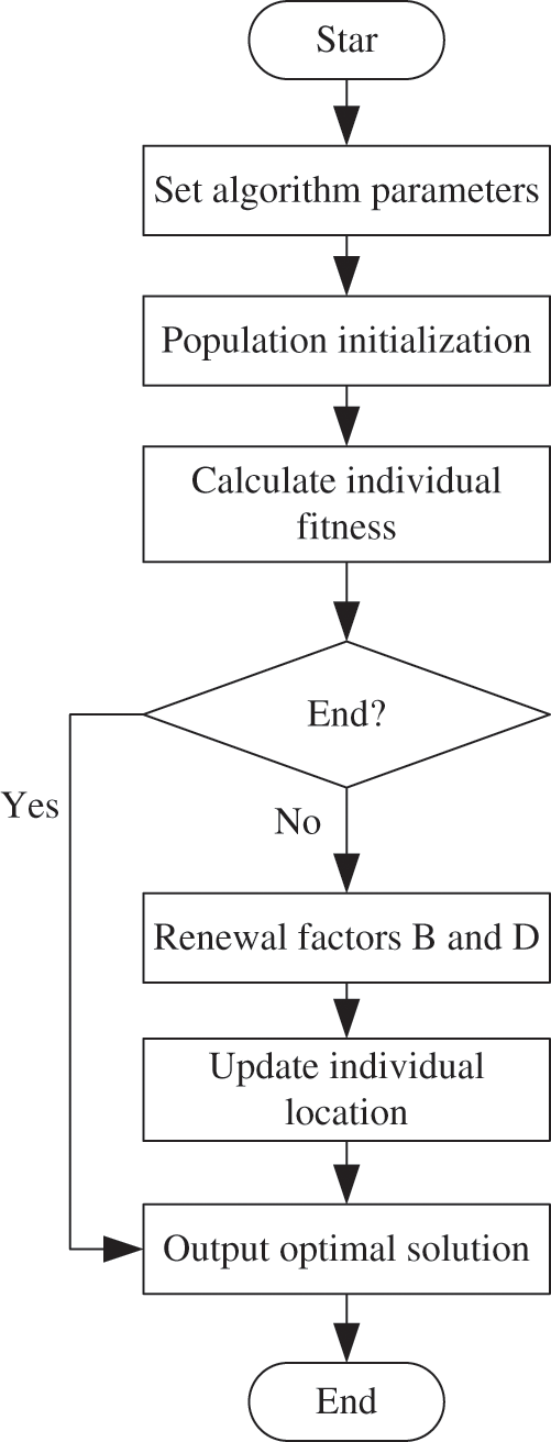
Figure 4: Flow chart of WWOA
To validate the effectiveness of the proposed method, the IEEE33 node system is used as a prototype. A MATLAB-based active distribution network model is constructed for simulation purposes, and a training and test dataset is generated. The topology of the network is depicted in Fig. 5, where each black node represents a distribution node. Two distributed power supplies are installed at nodes 21 and 32, while three relay protection devices (circuit breaker 1, circuit breaker 2, and circuit breaker 3) are set at nodes 18, 13, and 22, respectively. To supplement the actual data, the historical fault dataset of the distribution network is incorporated through MATLAB modeling and simulation. In the simulation, it is assumed that both the load and distributed generation (DG) outputs are subject to constant changes. The load and DG output data are randomly generated with variances of 4% to mimic realistic fluctuations.
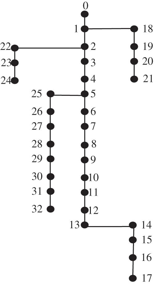
Figure 5: IEEE33 node structure
The method in this paper is used to locate the fault section of flexible DC distribution network compatible with distributed generation under different conditions. The results are shown in Table 3.
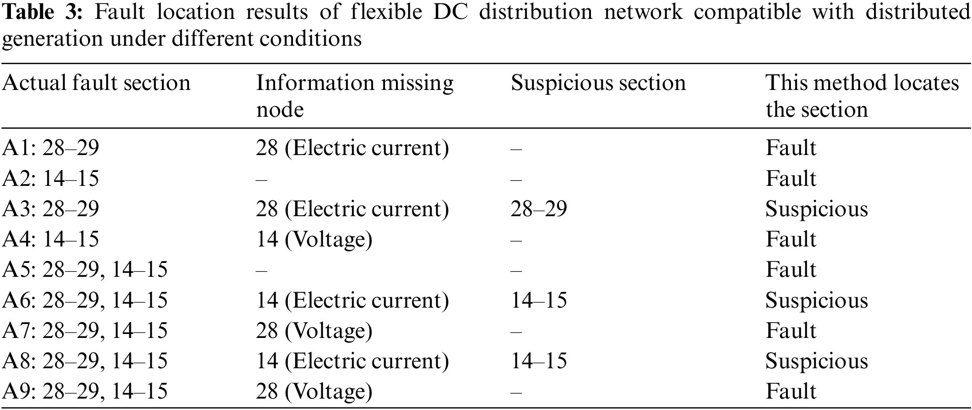
It can be seen from Table 3 that whether the voltage information of the fault section is distorted or not, if the section current data is accurate, it can be accurately located. If the current data is distorted, it will be identified as a suspicious section.
From the above results, it can be concluded that the method in this paper is not harsh on the distortion of topology global data and the number of fault branches, and can accurately locate multiple faults under the condition of ensuring the normal double-ended current data in the fault section. If the current data of double-ended data is distorted, it can be identified as a suspicious section, providing directional results and having certain fault tolerance. When the double-ended voltage data is missing, the location result will not be affected, and the fault section can still be accurately identified.
In order to better analyze the effect of adaptive weight and whale optimization algorithm on the setting and optimization of relay protection device settings, this paper lists the short-circuit currents under various conditions when DG is connected as shown in Table 4.
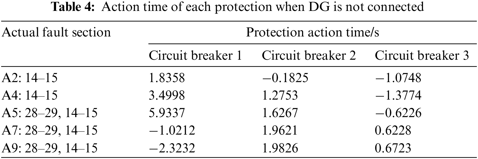
When DG is connected. In case of short circuit at different positions, the operation protection action time of each circuit breaker under the fixed value when DG is not connected is shown in Table 5. A negative value here indicates that the operation protection of the circuit breaker is not started.
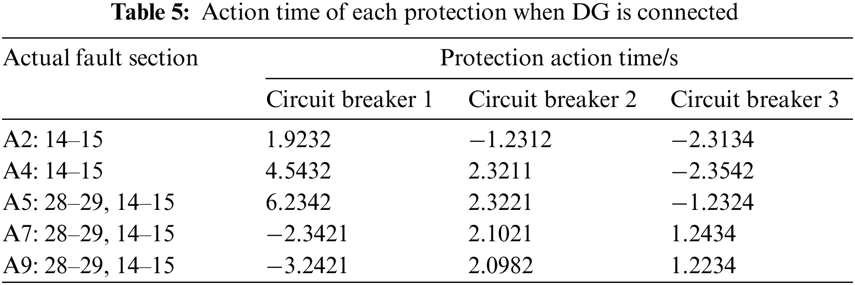
It can be seen from Table 5 that after DG connection, the protection action time of circuit breaker operation in case of failure of distribution network is relatively long, which has lost its practical significance.
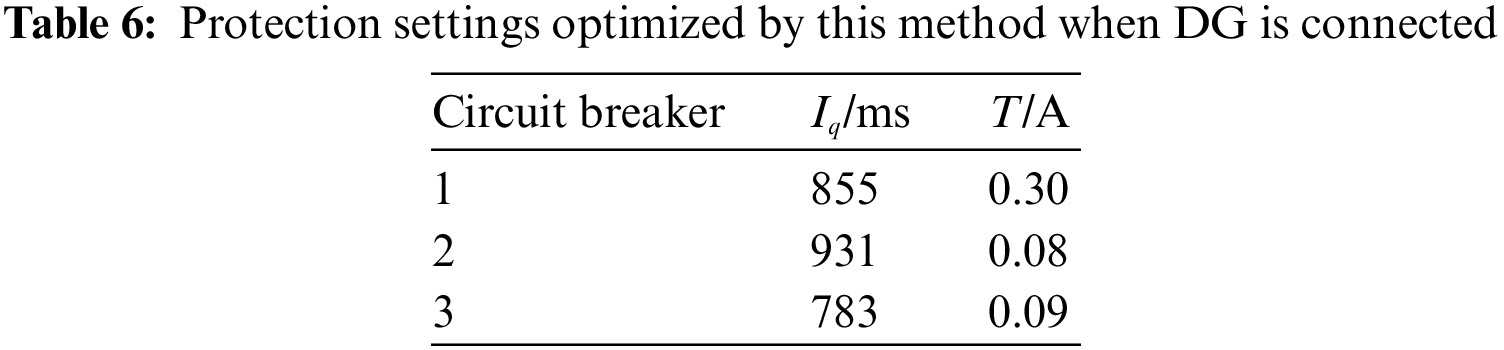
The adaptive weight and whale optimization algorithm is used to optimize the operation protection setting during DG access, as shown in Table 6.
The action time of the operation protection of each circuit breaker is recalculated according to the optimized setting value, as shown in Table 7.
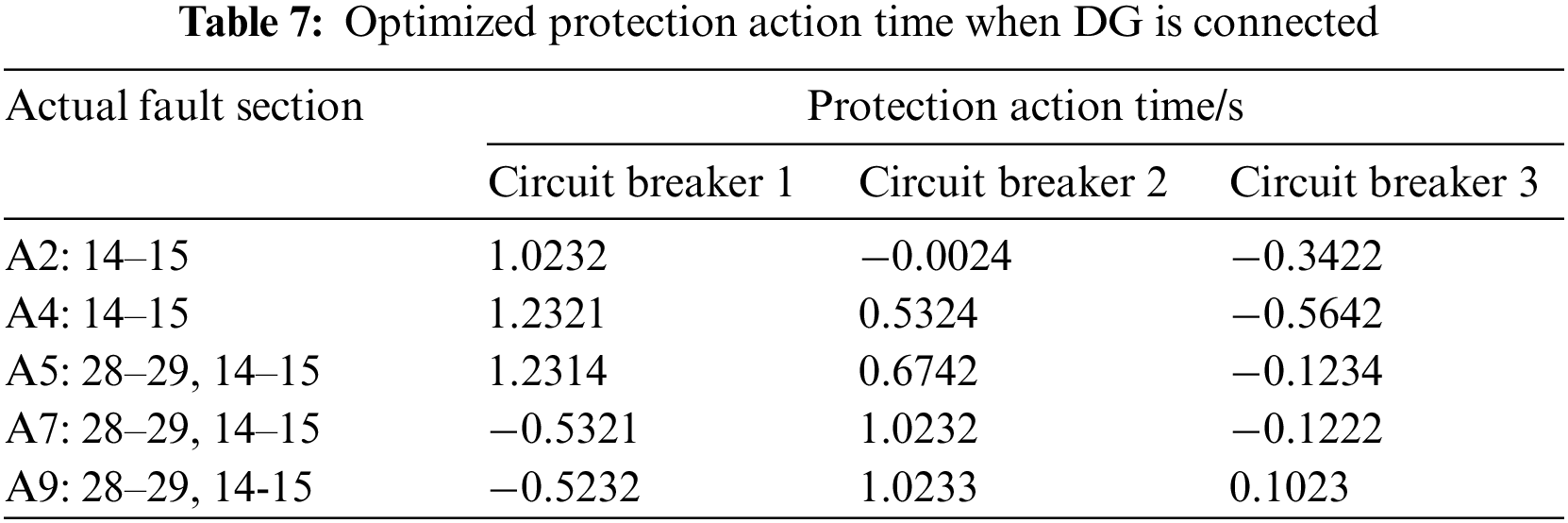
It can be seen from Table 7 that the operation time after optimization is reduced, The longest operation time is reduced by 4.7023 s, indicating that the response efficiency of the circuit breaker is improved at this time.
To assess the practicality of the proposed method, a comparative analysis is conducted to evaluate its effectiveness, along with two other methods from references [3] and [4], as well as a method without relay protection operation control. The analysis considers different fault conditions and examines the changes in impulse current during relay protection operation control after implementing the proposed method. The comparison results are depicted in the figure below.
It can be seen from Fig. 6 that in the case of distribution network ground fault, the maximum impulse current under the control of relay protection device is 4 A before the three methods are used for relay protection operation control. The maximum impulse current under the control of relay protection device is 2.2 A after adopting the method in reference [3]. The maximum impulse current under the control of relay protection device is 2.5 A after the method in reference [4] is adopted. After using the proposed method, the maximum impulse current under the control of relay protection device is 0.3 A, which shows that the method can effectively control the distribution network from the impact of large impulse current.
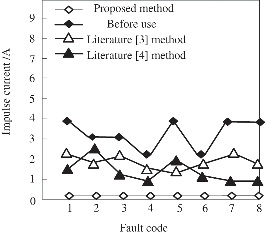
Figure 6: Duration change of grounding fault in distribution network
In the future, the development trend of relay protection is mainly reflected in the high integration and standardization of hardware and the multi-function of software. Its purpose is to make the relay protection system realize effective safe and reliable operation control of distribution network on the basis of increasingly perfect software and hardware.
(1) Computerization
With advancements in computer hardware, relay protection hardware has experienced significant growth and received strong technical support. As a result, the requirements for relay protection in power systems have been continuously elevated. Beyond basic protection functions, relay protection is expected to possess long-term storage capabilities for extensive fault information and data, swift data processing abilities, robust communication capabilities, networking capabilities with other protection and control devices, and integration with dispatching systems to facilitate data and resource sharing across the entire system. Moreover, high-level language programming is desired. These demands essentially require relay protection devices to function similarly to PCs. The computerization of relay protection devices is an irreversible trend. Nonetheless, further research is necessary to better meet power system requirements, enhance the reliability of relay protection, and achieve greater economic and social benefits.
(2) Intellectualization
In recent years, artificial intelligence technologies such as neural networks, genetic algorithms, evolutionary programming, fuzzy logic have been applied in various fields of power system, and the research in the field of relay protection has also begun. Neural network is a nonlinear mapping method. Many complex nonlinear problems that are difficult to list equations or solve can be solved easily by using neural network method. For example, when the system potential on both sides of the transmission line is tilted, the short circuit passing through the crossover resistance is a nonlinear problem, and the distance protection is difficult to correctly identify the fault location. Others, such as genetic algorithm and evolutionary programming, also have their unique ability to solve complex problems. Combining these artificial intelligence methods properly can make the solution speed faster. It can be predicted that artificial intelligence technology will be applied in the field of relay protection to solve the problems that are difficult to be solved by conventional methods.
To ensure the reliable operation of relay protection devices, it is crucial that they can automatically, swiftly, and selectively isolate failed components from the power system. This ensures that faultless parts can quickly return to normal operation while preventing further damage to the failed components. The future reliability of relay protection is an important aspect of its sustainable development. Therefore, conducting comprehensive research on relay protection operation and control methods holds significant practical significance. In this paper, a relay protection operation control method for flexible DC distribution networks with distributed power supply is proposed. The method utilizes the adaptive weight and whale optimization algorithm to construct an objective function for distribution network protection operation control. A case study using a basic example system is conducted to verify the effectiveness of the proposed method. The results demonstrate practical reductions in the longest operation time by 4.7023 s and a maximum impulse current of 0.3 A under the control of the relay protection device. However, during the operation control of distribution network relay protection, the complexity of the algorithm led to longer-than-expected operation times, thereby reducing control efficiency. In future studies, efforts will be made to improve the algorithm, aiming to shorten operation times and enhance the control efficiency of relay protection devices.
Acknowledgement: Not applicable.
Funding Statement: The author received no specific funding for this study.
Author Contributions: This article was written independently by Zihan Qi.
Availability of Data and Materials: The data are available from the corresponding author on reasonable request.
Conflicts of Interest: The author declares that they have no conflicts of interest to report regarding the present study.
References
1. Aririguzo, J. C., Ekwe, E. B. (2019). Weibull distribution analysis of wind energy prospect for Umudike, Nigeria for power generation. Robotics and Computer-Integrated Manufacturing, 55, 160–163. https://doi.org/10.1016/j.rcim.2018.01.001 [Google Scholar] [CrossRef]
2. Grigoriev, A. S., Grigoriev, S. A., Korolev, A. V. (2019). Small autonomous kW-level power generation based on radioisotope and renewable energy sources for the arctic zone and the far east. Atomic Energy, 125(4), 231–238. https://doi.org/10.1007/s10512-019-00472-x [Google Scholar] [CrossRef]
3. Hamidan, M. A., Borousan, F. (2022). Optimal planning of distributed generation and battery energy storage systems simultaneously in distribution networks for loss reduction and reliability improvement. Journal of Energy Storage, 46(2), 1–18. https://doi.org/10.1016/j.est.2021.103844 [Google Scholar] [CrossRef]
4. Liu, Y., Zhu, W., Li, L. (2020). Analysis and design of intelligent management and control system for relay protection based on information fusion technology. Journal of Physics: Conference Series, 1624(6), 062013. https://doi.org/10.1088/1742-6596/1624/6/062013 [Google Scholar] [CrossRef]
5. Popovic, Z. N., Knezevic, S. D., Kerleta, V. D. (2019). Network automation planning in distribution networks with distributed generators using a risk-based approach. Electrical Engineering, 101(2), 659–673. https://doi.org/10.1007/s00202-019-00814-9 [Google Scholar] [CrossRef]
6. Motepe, S., Hasan, A. N., Twala, B. (2019). Effective load forecasting for large power consuming industrial customers using long short-term memory recurrent neural networks. Journal of Intelligent and Fuzzy Systems, 37(3), 1–17. https://doi.org/10.3233/JIFS-190658 [Google Scholar] [CrossRef]
7. Wang, Q. (2022). Feeder segment switch-based relay protection for a multilayer differential defense-oriented distribution network. Soft Computing, 26(10), 4895–4904. https://doi.org/10.1007/s00500-021-06673-6 [Google Scholar] [CrossRef]
8. Richards, R. J., Paul, A. (2021). An attention-driven long short-term memory network for high throughput virtual screening of organic photovoltaic candidate molecules. Solar Energy, 224, 43–50. https://doi.org/10.1016/j.solener.2021.05.064 [Google Scholar] [CrossRef]
9. Sun, H., Yi, H., Zhuo, F. (2020). Precise fault location in distribution networks based on optimal monitor allocation. IEEE Transactions on Power Delivery, 35(4), 1788–1799. https://doi.org/10.1109/TPWRD.2019.2954460 [Google Scholar] [CrossRef]
10. Alam, A., Pant, V., Das, B. (2020). Optimal placement of protective devices and switches in a radial distribution system with distributed generation. IET Generation Transmission & Distribution, 14(21), 4847–4858. https://doi.org/10.1049/iet-gtd.2019.1945 [Google Scholar] [CrossRef]
11. Bassan, F. R., Rosolem, J. B., Floridia, C. (2021). Power-over-fiber LPIT for voltage and current measurements in the medium voltage distribution networks. Sensors, 21(2), 547. https://doi.org/10.3390/s21020547 [Google Scholar] [PubMed] [CrossRef]
12. Xu, G., Zhang, G. (2021). Two-stage stochastic scheduling approach for AC/DC hybrid distribution system with renewable energy integration. Electrical Engineering, 103(1), 43–55. https://doi.org/10.1007/s00202-020-01047-x [Google Scholar] [CrossRef]
13. Chen, K., Hu, J., Zhang, Y. (2020). Fault location in power distribution systems via deep graph convolutional networks. IEEE Journal on Selected Areas in Communications, 38(1), 119–131. https://doi.org/10.1109/JSAC.2019.2951964 [Google Scholar] [CrossRef]
14. Dadfar, S., Gandomkar, M. (2021). Augmenting protection coordination index in interconnected distribution electrical grids: Optimal dual characteristic using numerical relays. International Journal of Electrical Power & Energy Systems, 131(29), 107107. https://doi.org/10.1016/j.ijepes.2021.107107 [Google Scholar] [CrossRef]
15. Saikrishna, R., Rajalwal, N. K., Ghosh, D. (2022). Adaptive relay co-ordination using a busbar splitting approach for a system integrity protection scheme. Protection and Control of Modern Power Systems, 7(1), 1–12. https://doi.org/10.1186/s41601-022-00235-0 [Google Scholar] [CrossRef]
16. Tiwari, R., Singh, R. K., Choudhary, N. K. (2022). Coordination of dual setting overcurrent relays in microgrid with optimally determined relay characteristics for dual operating modes. Protection and Control of Modern Power Systems, 7(1), 1–18. https://doi.org/10.1186/s41601-022-00226-1 [Google Scholar] [CrossRef]
17. Liao, C., Erbaugh, J. T., Kelly, A. C. (2021). Clean energy transitions and human well-being outcomes in lower and middle income countries: A systematic review. Renewable and Sustainable Energy Reviews, 145(15), 111063. https://doi.org/10.1016/j.rser.2021.111063 [Google Scholar] [CrossRef]
18. Wu, X., Xu, C., Wei, B. (2021). H∞ mixed sensitivity robust control method of relay ICPT system for output voltage regulation. Electrical Engineering, 103(2), 1–12. https://doi.org/10.1007/s00202-020-01116-1 [Google Scholar] [CrossRef]
19. Velazquez, J., Galvan, R., Fridman, L. (2019). Two relay control robustification by continuous switched integral sliding modes. IET Control Theory and Applications, 13(9), 1374–1382. https://doi.org/10.1049/iet-cta.2018.5639 [Google Scholar] [CrossRef]
20. Guo, Z. Z., Hao, Y. R., Gong, C. Q. (2021). Social learning whale optimization algorithm. Computer Simulation, 38(6), 219–225. [Google Scholar]
Cite This Article
 Copyright © 2023 The Author(s). Published by Tech Science Press.
This work is licensed under a Creative Commons Attribution 4.0 International License , which permits unrestricted use, distribution, and reproduction in any medium, provided the original work is properly cited.
 Downloads
 Citation Tools