
 Submit a Paper
 Propose a Special lssue
 Open Access
ARTICLE

System Energy and Efficiency Analysis of 12.5 W VRFB with Different Flow Rates
1 School of Energy and Power Engineering, Changsha University of Science and Technology, Changsha, 410114, China
2 Hunan Vanadium Valley New Energy Technology Co., Ltd., Changsha, 410114, China
3 Big Pawer Electrical Technology Xiangyang Co., Ltd., Xiangyang, 441057, China
* Corresponding Author: Chuanchang Li. Email:
(This article belongs to the Special Issue: Energy Systems Management and Climate Change)
Energy Engineering 2023, 120(12), 2903-2915. https://doi.org/10.32604/ee.2023.027636
Received 07 November 2022; Accepted 13 February 2023; Issue published 29 November 2023
 View Full Text
 Download PDF
Abstract
Vanadium redox flow battery (VRFB) is considered one of the most potential large-scale energy storage technologies in the future, and its electrolyte flow rate is an important factor affecting the performance of VRFB. To study the effect of electrolyte flow rate on the performance of VRFB, the hydrodynamic model is established and a VRFB system is developed. The results show that under constant current density, with the increase of electrolyte flow rate, not only the coulombic efficiency, energy efficiency, and voltage efficiency will increase, but also the capacity and energy discharged by VRFB will also increase. But on the other hand, as the flow rate increases, the power of the pump also increases, resulting in a decrease in system efficiency. The energy discharged by the system does not increase with the increase in flow rate. Considering the balance between efficiency and pump power loss, it is experimentally proved that 120 mL·min−1 is the optimal working flow rate of the VRFB system, which can maximize the battery performance and discharge more energy.Keywords
Renewable energy sources, such as wind and solar, that produce little pollutants have grown rapidly as environmental problems have grown [1]. However, the intermittency and instability of renewable energy generation will bring enormous pressure on the existing grid [2–6]. To address these challenges, energy storage technologies have been developed to mitigate the impact of renewable energy generation on the grid [7–10]. Vanadium redox flow battery (VRFB) is a relatively new energy storage technology in electrochemical energy storage technology, and it is also one of the most potential large-scale energy storage technology with long life and low cost in the future [11–15]. Different from the traditional battery, the energy of VRFB is not stored in the electrode but in the electrolyte [16]. The electrolyte is continuously circulated under the action of the pump to realize the charging and discharging of the battery. The schematic diagram of VRFB is shown in Fig. 1.
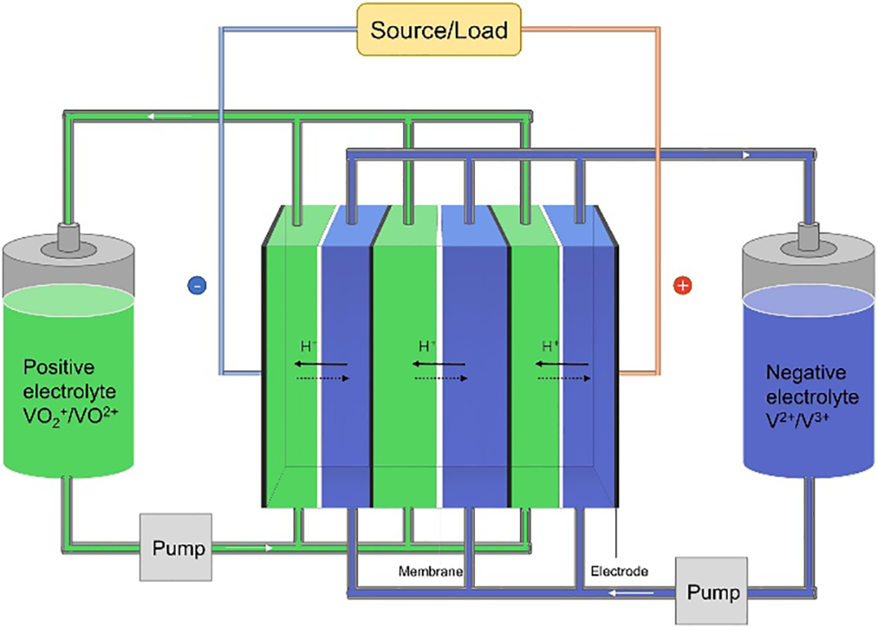
Figure 1: Operating principle diagram of vanadium redox flow battery
Early research on VRFB was pioneered by Skyllas-Kazacos et al. [17] in the 1980s. Since then, many scholars have carried out a lot of research work to improve its performance. To improve the performance of VRFB, researchers focus on the improvement of battery components, especially electrodes, electrolytes, and membranes [18–23]. In addition, some researchers focus on establishing a simulation model to optimize charging-discharging operations [24–26] and battery capacity attenuation methods during the cycle [27,28]. Few studies on electrolyte flow rate are mentioned [29].
In the actual operation of VRFB, the electrolyte flow rate is an important factor affecting VRFB, which affects the heat exchange between the stack and the environment, the mass transfer of reactants, and the power consumption of the pump. Al-Fetlawi et al. [30] found that a high electrolyte flow rate not only maintains uniformity of temperature distribution but also increases the coulombic efficiency of the cell and reduces the hydrogen and oxygen release rates. To further consider the mass transfer effect of the reactants, König et al. [31] believed that it is reasonable to increase the electrolyte flow rate under low and high SOC conditions. The effect of electrolyte flow rate on the change of vanadium ion concentration and concentration overpotential during the charging and discharging process of the battery cannot be ignored. Li et al. [32] established a hydrodynamic model considering the fluid flow and confirmed that the concentration change of vanadium ions is determined by the electrochemical reaction and the electrolyte flow rate simultaneously. Although a high electrolyte flow rate can solve the problem of high concentration overpotential and improve the utilization rate of electrolytes, it will also increase the pump power. Xiong et al. [33] proposed the optimal flow rate of VRFB in a charge-discharge cycle, that is, the operating flow rate that maximizes the discharge energy and minimizes the charge energy in one cycle.
In this paper, a hydrodynamic model is established, and the principle and process of model building are explained and analyzed. According to the built model combined with the experiment, the influence of the electrolyte flow rate on the performance of VRFB at a current density of 120 mA·cm−2 was analyzed, and the system efficiency and energy discharged by the VRFB were evaluated. Finally, the optimal flow rate for VRFB charge-discharge operation was determined experimentally.
In the vanadium redox flow battery, in addition to the electrochemical reaction in the stack, it is also necessary to consider the influence of the circulating pump and the electrolyte flow rate in the stack structure on the battery. In this study, a hydrodynamic model was established, considering the electrolyte transport phenomena at different flow rates and verified by experiments to calculate the pumping energy consumption and evaluate the performance of VRFB. In addition to the need to overcome the gravitational potential energy, the circulating electrolyte also produces gravitational losses, both of which are related to the power of the pump. In the VRFB system, the pressure loss of the electrolyte flow is relatively more significant, and the work done to overcome the gravitational potential energy can generally be ignored in the calculation [30]. The pressure loss of the electrolyte flow rate is usually related to the loss in the pipe, flow frame, and porous electrode. All the pressure loss can be divided into the friction resistance loss
The friction loss
where
where
where
The congestion loss
where
2.3 Pressure Losses in the Flow Frame
The flow frame of a vanadium redox flow battery typically consists of branches and channels that transport electrolytes into each half-cell of the stack, allowing redox reactions to occur on both sides of the ion-exchange membrane. Using the relevant flow frame design parameters, the pressure losses through the branches and channels can also be calculated according to the Darcy-Weisbach equation. The loss
2.4 Pressure Losses in Porous Graphite Felt Electrode
Porous graphite felt electrodes can also cause pressure loss in electrolyte flow. The pressure loss of porous medium can generally be calculated by Darcy’s law, so the pressure loss
where
where
The total pressure loss of the electrolyte flow in the VRFB system is the sum of all the above pressure losses. Based on the hydrodynamic model, the power loss of the pump is shown in Eq. (10).
where
In evaluating the performance of a VRFB, efficiency can be assessed based on four metrics: system efficiency, coulombic efficiency, energy efficiency, and voltage efficiency. System efficiency measures the ratio of energy discharged by the system to energy input. Coulombic efficiency quantifies the ratio of electricity discharged by the battery to electricity input. Energy efficiency represents the ratio of energy discharged by the battery to energy input. Voltage efficiency, on the other hand, calculates the ratio of energy efficiency to coulombic efficiency. The respective calculation formulas for these four efficiencies are as follows:
where
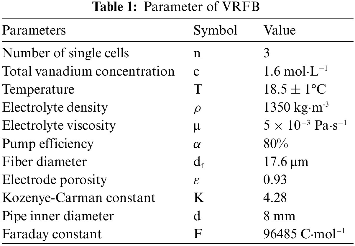
Generally, it is difficult to enhance both system efficiency and energy efficiency at the same time in most cases. In this study, priority should be given to improving system efficiency and system discharge energy, and on this basis, improve energy efficiency as much as possible. Some parameters (electrolyte density, viscosity, electrode parameters, etc.) of VRFB in the hydrodynamic model are measured previously, as shown in Table 1.
To study the effect of electrolyte flow rate on VRFB performance, a VRFB system was fabricated. The VRFB system consists of a VRFB stack, a pump, two electrolyte tanks, and several pipes connecting all the equipment. Each single battery is composed of the following components: two carbon felt as the positive and negative electrodes of the battery (expanded graphite, area: 24 cm2 and thickness: 0.8 mm); Ion exchange membrane (Kerun membrane); carbon composite bipolar plate; current collector (copper alloy); flow frame (flow field: multiple channels in parallel). This experiment uses self-made electrolyte, which is composed of 9.55% VOSO4, 11.42% V2(SO4)3, 15.79% H2SO4, and 63.24% H2O. The electrolyte volume in the VRFB system was 0.1 L and contained 1.6 mol·L−1 of vanadium ion electrolyte. In this experiment, the voltage range and current density of the VRFB stack can be adjusted by a charge-discharge tester, and a constant current charge-discharge method is used for each working condition. The operating temperature of the VRFB stack is 18.5°C, the voltage range is 3.0–4.8 V, and the current density is 120 mA·cm−2.
3.2 Performance Test of Vanadium Redox Flow Battery
According to Faraday’s law, Merei et al. obtained the theoretical electrolyte flow rate of the VRFB system [34], as shown in Eq. (15).
where
Based on the data in Table 1 and calculated according to Eq. (15), the theoretical flow rate
When the rate of electrolyte flow increases, the power loss in the pump also increases, resulting in reduced efficiency of the battery system during charging and discharging. Conversely, decreasing the flow rate of the electrolyte reduces the concentration of vanadium ions involved in the chemical reaction. This, in turn, leads to an increase in concentration overpotential, causing a decrease in the energy efficiency of the vanadium redox flow battery. Moreover, the concentration of vanadium ions affects the state of charge (SOC) of the battery, influencing the voltage of individual cells (
The VRFB system was placed in a constant temperature environment. Charge-discharge cycles were performed at a current density of 120 mA·cm−2 at constant flow rates of 40, 80, 120, 160, and 200 mL·min−1, respectively. The coulombic efficiency, energy efficiency, and voltage efficiency of VRFB are shown in Fig. 2. The data indicates that with an increase in flow rate from 40 to 200 mL·min−1, there is an upward trend in coulombic efficiency, rising from 97.57% to 98.15%. Additionally, the voltage efficiency experiences a positive trend, increasing from 81.69% to 83.88%. Similarly, a rise in energy efficiency can be observed, ascending from 79.71% to 82.33%.
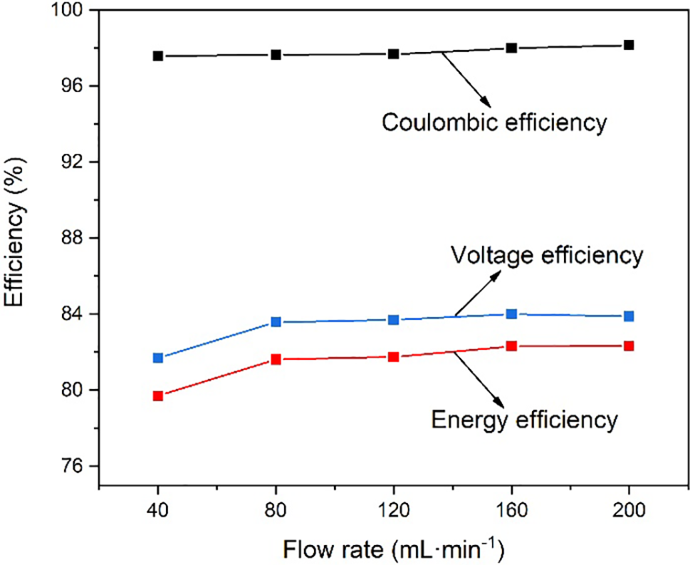
Figure 2: Coulombic efficiency, voltage efficiency and energy efficiency with different flow rates
Fig. 3 shows the charge-discharge curves at 120 mA·cm−2 operation. It can be seen that during the charging process when the battery is at the same voltage, the greater the flow rate of electrolyte, the greater the amount of capacity charged. On the other hand, during the discharge process, when the battery is at the same voltage, the greater the electrolyte flow rate, the greater the amount of capacity discharged. Fig. 4 shows the charged capacity and energy and the discharged capacity and energy when running at 120 mA·cm−2. When the flow rate of the electrolyte increases, the amount of capacity and energy charged into the battery increases; at the same time, the amount of capacity and energy discharged from the VRFB also increases. The increase in the electrolyte flow rate can increase the vanadium ions participating in the chemical reaction inside the battery, thereby increasing the battery capacity. However, when the electrolyte flow rate increased from 160 to 200 mL·min−1, the charged capacity increased by 17.3 mAh, and the discharged capacity increased by 18.7 mAh, with a relatively small increase. The reason for this phenomenon may be that when the electrolyte flow rate increases to 200 mL·min−1, the concentration of vanadium ions involved in the chemical reaction is sufficient, and the difference between the concentration of vanadium ions in the stack and the concentration of vanadium ions in the storage tank is small.
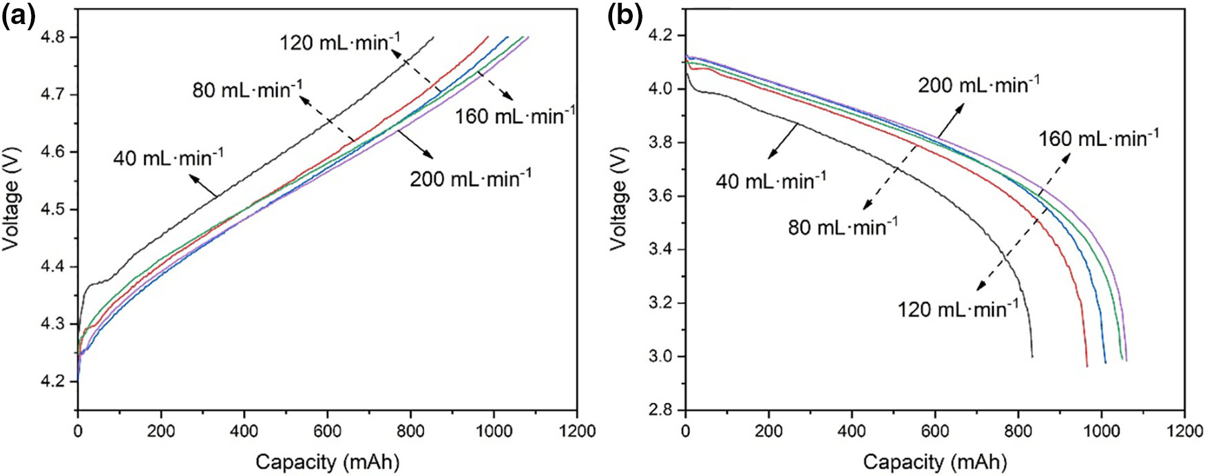
Figure 3: (a) Charge curves and (b) discharge curves with different flow rates
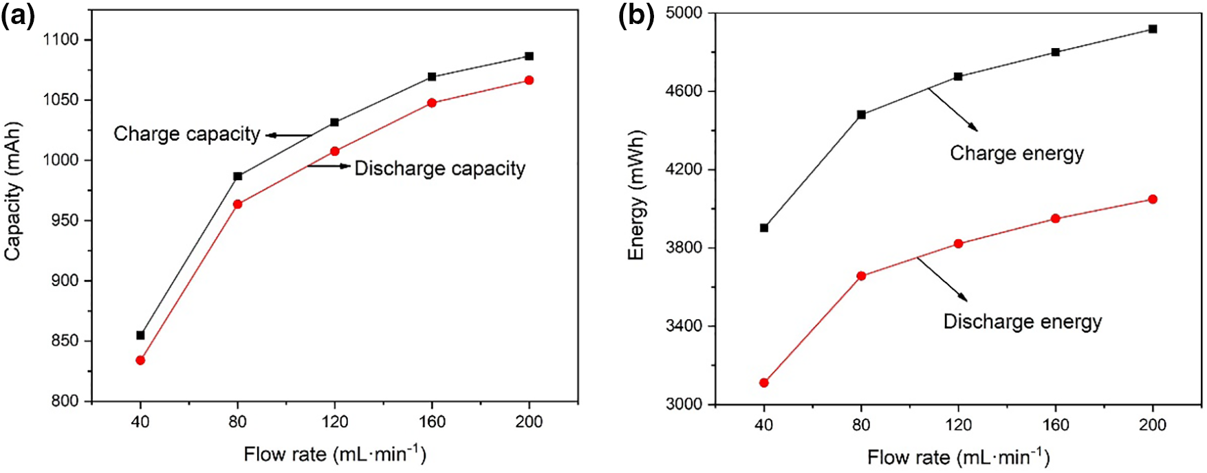
Figure 4: (a) Charge-discharge capacity and (b) charge-discharge energy with different flow rates
The overpotentials of batteries are generally divided into concentration overpotentials, activation overpotentials, and ohmic overpotentials [35,36]. Fig. 5 further depicts the change in stack voltage during a single charge-discharge cycle at different flow rates. In Fig. 5, there is an intermediate phase between the charging phase and the discharging phase that neither charges nor discharges, so the battery voltage stabilizes after charging. Due to concentration overvoltage and activation overvoltage, the voltage of VRFB will step descent after charging. It can be observed that the overpotential of the VRFB is larger when the flow rate is 40 mL·min−1. With the increase in flow rate, the overpotential of the battery gradually decreases [37]. Electrolyte flow rate plays an important role in the operation of vanadium redox flow batteries. The increase in the electrolyte flow rate can reduce the concentration difference of vanadium ions in the stack and the electrolyte storage tank, thereby reducing the concentration overpotential and improving the energy efficiency of the battery [38]. However, although the increase of the electrolyte flow rate can increase the concentration of vanadium ions participating in the electrochemical reaction in the stack, it cannot reduce the time used for one charge-discharge cycle. It can be known from Fig. 4 that the charging and discharging time of VRFB increases with the increase in battery capacity.
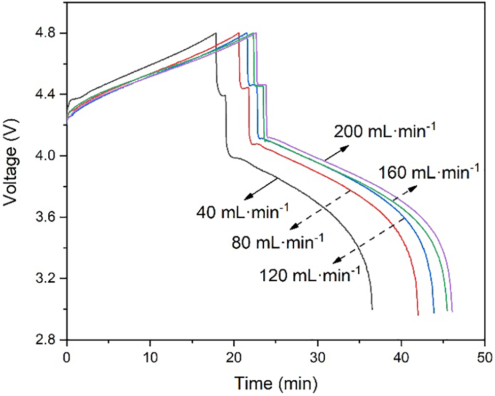
Figure 5: Charge-discharge stack voltage vs. time with different flow rates
As previously mentioned, a higher flow rate of the electrolyte can reduce concentration overpotential and enhance battery efficiency. However, it simultaneously leads to increased pump power loss. The evaluation of the vanadium redox flow battery’s performance encompasses not only the battery’s energy and efficiency but also the VRFB system efficiency. To accurately calculate these energies, it is necessary to consider the energy consumption of the pump. Consequently, excessive flow rates can result in elevated energy losses during the pump operation, potentially impacting the overall efficiency of the battery system [33].
In this paper, we examine the efficiency of the VFB system in terms of flow rate considering the power consumption of the pump. The power of the pump is calculated from the pipeline pressure drop, flow rate, and pump efficiency, which is related to the system efficiency as shown in Table 2. For the entire VRFB system, system efficiency is often more important than energy efficiency. Based on the hydrodynamic model, the pump power is calculated by Eq. (10), and the system efficiency is calculated by Eq (11). It can be seen that at the low flow rate, the pump power remains low, but as the flow rate increases, the pump power will increase in a quadratic curve and the system efficiency will continue to decrease [39], as shown in Fig. 6. Fig. 7 shows the VRFB discharge energy and system discharged energy with different electrolyte flow rates. When the electrolyte flow rate is 120 mL·min−1, the system discharge power is 3647.66 mAh. Although the increase in flow will lead to an increase in capacity, it will also lead to an increase in pump power. When the electrolyte flow rate increased to 160 mL·min−1, the discharged capacity of the system decreased to 3633.03 mAh. Because the system discharge energy takes into account the loss of pump power, the energy discharged by the VRFB must be less than the system discharge energy. Through the established hydrodynamic model, the pump loss power and system efficiency under different flow rates are calculated. Combined with the performance parameters such as energy efficiency and discharge quantity, it is determined that the optimal operating flow rate is 120 mL·min−1 when charging and discharging at 120 mA·cm−2 current density.
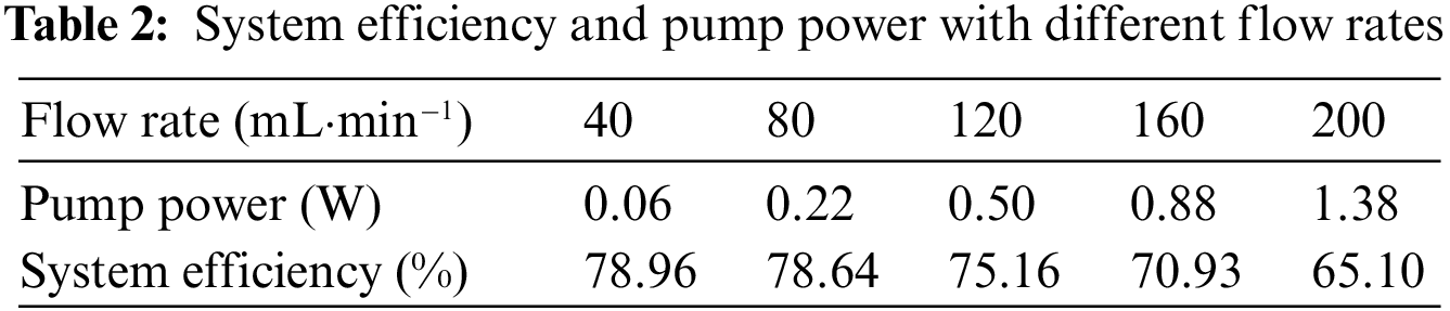
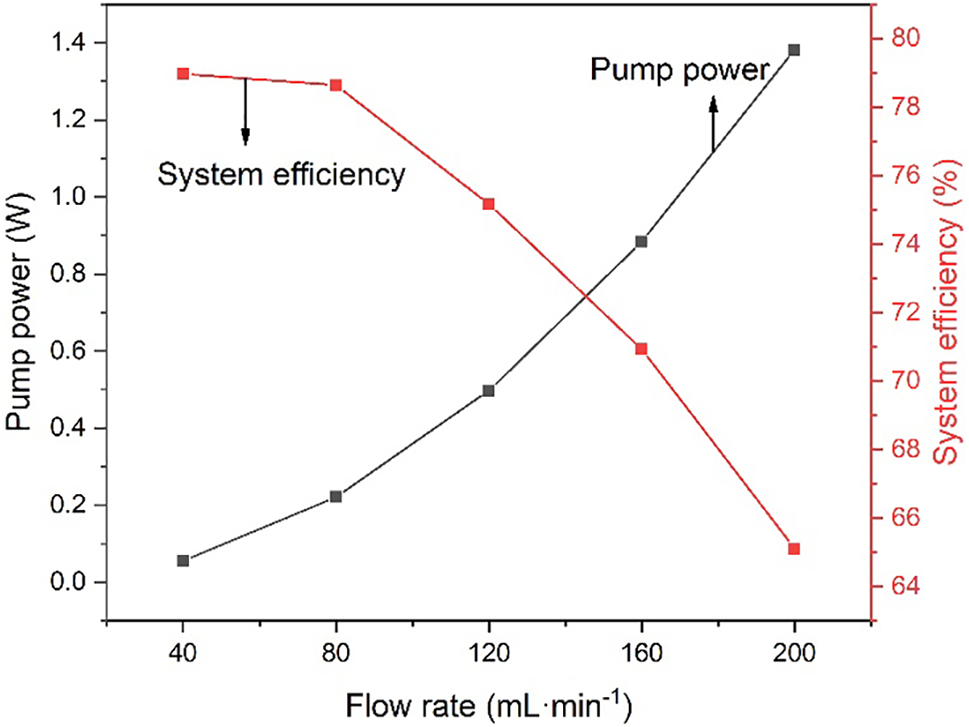
Figure 6: System efficiency and pump power with different flow rates
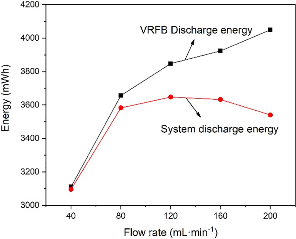
Figure 7: System discharge energy and VRFB discharge energy with different flow rates
The effect of electrolyte flow rate on the performance of VRFB was studied by establishing a hydrodynamic model and assembling a VRFB system to conduct experiments. The results show that the concentration overpotential decreases with the increase of electrolyte flow rate under constant current density. Not only will the coulombic efficiency, energy efficiency, and voltage efficiency increase, but also the amount of capacity and energy discharged by the VRFB will increase. However, with the increase of electrolyte flow rate, the power of the pump will also increase, and the system efficiency will decrease at the same time. In the experiment, the flow rate was increased from 40 to 200 mL·min−1, and the energy discharged by the system did not increase continuously. When the flow rate is 120 mL·min−1, the system discharges the maximum energy, which is 3647.66 mAh. The system efficiency is 75.16%, and the energy efficiency is 81.75%. All in all, 120 mL·min−1 is the optimal operating flow rate under the current density of 120 mA·cm−2. In a practical VRFB system, the balance between efficiency and pump power loss needs to be considered. In particular, when evaluating the performance of the VRFB, the energy discharged by the entire system should be used as the standard rather than the energy discharged by the VRFB. Hence, the investigation of electrolyte flow rate control holds significance in vanadium redox flow battery systems and warrants further examination.
Acknowledgement: This work was supported by the Special Fund for the Construction of Innovative Province in Hunan Province, China (2020RC3038); and the Changsha City Fund for Distinguished and Innovative Young Scholars, China (kq1802007).
Funding Statement: This work was supported by the Special Fund for the Construction of Innovative Province in Hunan Province, China (2020RC3038); and the Changsha City Fund for Distinguished and Innovative Young Scholars, China (kq1802007).
Author Contributions: Kehuan Xie: Methodology, Validation, Formal analysis, Investigation, Data curation, Writing–original draft. Longhai Yu: Conceptualization, Methodology, Resources, Investigation, Writing–review & editing, Supervision. Chuanchang Li: Conceptualization, Methodology, Resources, Investigation, Writing–review & editing, Supervision, Project administration, Funding acquisition.
Availability of Data and Materials: The datasets used and/or analysed during the current study are available from the corresponding author on reasonable request.
Conflicts of Interest: The authors declare that they have no conflicts of interest to report regarding the present study.
References
1. Panwar, N. L., Kaushik, S. C., Kothari, S. (2011). Role of renewable energy sources in environmental protection: A review. Renewable and Sustainable Energy Reviews, 15(3), 1513–1524. [Google Scholar]
2. Zheng, B., Fletcher, J. E., Lennon, A., Jiang, Y., Burr, P. A. (2019). Improving generation ramp rates of photovoltaic systems using module-based capacitive energy storage. Journal of Power Sources, 423, 227–235. [Google Scholar]
3. Liu, J., Wen, J., Yao, W., Long, Y. (2016). Solution to short-term frequency response of wind farms by using energy storage systems. IET Renewable Power Generation, 10(5), 669–678. [Google Scholar]
4. McCormick, P. G., Suehrcke, H. (2018). The effect of intermittent solar radiation on the performance of PV systems. Solar Energy, 171, 667–674. [Google Scholar]
5. Kandasamy, N. K., Tseng, K. J., Boon-Hee, S. (2017). Virtual storage capacity using demand response management to overcome intermittency of solar PV generation. IET Renewable Power Generation, 11(14), 1741–1748. [Google Scholar]
6. Li, Y., Sun, L., Cao, L., Bao, J., Skyllas-Kazacos, M. (2021). Dynamic model based membrane permeability estimation for online SOC imbalances monitoring of vanadium redox flow batteries. Journal of Energy Storage, 39, 102688. [Google Scholar]
7. Li, L., Liu, P., Li, Z., Wang, X. (2018). A multi-objective optimization approach for selection of energy storage systems. Computers & Chemical Engineering, 115, 213–225. [Google Scholar]
8. Luo, X., Wang, J., Dooner, M., Clarke, J. (2015). Overview of current development in electrical energy storage technologies and the application potential in power system operation. Applied Energy, 137, 511–536. [Google Scholar]
9. Díaz-González, F., Sumper, A., Gomis-Bellmunt, O., Villafáfila-Robles, R. (2012). A review of energy storage technologies for wind power applications. Renewable and Sustainable Energy Reviews, 16(4), 2154–2171. [Google Scholar]
10. Lourenssen, K., Williams, J., Ahmadpour, F., Clemmer, R., Tasnim, S. (2019). Vanadium redox flow batteries: A comprehensive review. Journal of Energy Storage, 25, 100844. [Google Scholar]
11. Li, J., Hu, D., Mu, G., Wang, S., Zhang, Z. et al. (2020). Optimal control strategy for large-scale VRB energy storage auxiliary power system in peak shaving. International Journal of Electrical Power & Energy Systems, 120, 106007. [Google Scholar]
12. Akter, M., Li, Y., Bao, J., Skyllas-Kazacos, M., Rahman, M. (2019). Optimal charging of vanadium redox flow battery with time-varying input power. Batteries, 5(1), 5010020. [Google Scholar]
13. Li, X., Zhang, H., Mai, Z., Zhang, H., Vankelecom, I. (2011). Ion exchange membranes for vanadium redox flow battery (VRB) applications. Energy & Environmental Science, 4(4), 1147–1160. [Google Scholar]
14. Skyllas-Kazacos, M., Chakrabarti, M. H., Hajimolana, S. A., Mjalli, F. S., Saleem, M. (2011). Progress in flow battery research and development. Journal of the Electrochemical Society, 158(8), R55–R79. [Google Scholar]
15. Huang, Z., Mu, A., Wu, L., Yang, B., Qian, Y. et al. (2022). Comprehensive analysis of critical issues in all-vanadium redox flow battery. ACS Sustainable Chemistry & Engineering, 10(24), 7786–7810. [Google Scholar]
16. Ponce de León, C., Frías-Ferrer, A., González-García, J., Szánto, D. A., Walsh, F. C. (2006). Redox flow cells for energy conversion. Journal of Power Sources, 160(1), 716–732. [Google Scholar]
17. Skyllas-Kazacos, M., Rychcik, M., Robins, R. G., Fane, A. G. (1986). New all-vanadium redox flow cell. Journal of the Electrochemical Society, 133, 1057. [Google Scholar]
18. Ngamsai, K., Arpornwichanop, A. (2015). Investigating the air oxidation of V(II) ions in a vanadium redox flow battery. Journal of Power Sources, 295, 292–298. [Google Scholar]
19. Lu, W., Li, X., Zhang, H. (2017). The next generation vanadium flow batteries with high power density—A perspective. Physical Chemistry Chemical Physics, 20(1), 23–35. [Google Scholar] [PubMed]
20. Lv, Y., Li, Y., Han, C., Chen, J., He, Z. et al. (2020). Application of porous biomass carbon materials in vanadium redox flow battery. Journal of Colloid and Interface Science, 566, 434–443. [Google Scholar] [PubMed]
21. Xu, Y., Wei, W., Cui, Y., Liang, H., Nian, F. (2018). Sulfonated polyimide/phosphotungstic acid composite membrane for vanadium redox flow battery applications. High Performance Polymers, 31(6), 679–685. [Google Scholar]
22. He, Z., Jiang, Y., Li, Y., Zhu, J., Zhou, H. et al. (2018). Carbon layer-exfoliated, wettability-enhanced, SO3H-functionalized carbon paper: A superior positive electrode for vanadium redox flow battery. Carbon, 127, 297–304. [Google Scholar]
23. Tempelman, C. H. L., Jacobs, J. F., Balzer, R. M., Degirmenci, V. (2020). Membranes for all vanadium redox flow batteries. Journal of Energy Storage, 32, 101754. [Google Scholar]
24. Wei, Z., Meng, S., Tseng, K. J., Lim, T. M., Soong, B. H. et al. (2017). An adaptive model for vanadium redox flow battery and its application for online peak power estimation. Journal of Power Sources, 344, 195–207. [Google Scholar]
25. Wei, Z., Lim, T. M., Skyllas-Kazacos, M., Wai, N., Tseng, K. J. (2016). Online state of charge and model parameter co-estimation based on a novel multi-timescale estimator for vanadium redox flow battery. Applied Energy, 172, 169–179. [Google Scholar]
26. Li, Y., Zhang, X., Bao, J., Skyllas-Kazacos, M. (2017). Studies on optimal charging conditions for vanadium redox flow batteries. Journal of Energy Storage, 11, 191–199. [Google Scholar]
27. Jirabovornwisut, T., Arpornwichanop, A. (2019). A review on the electrolyte imbalance in vanadium redox flow batteries. International Journal of Hydrogen Energy, 44(45), 24485–24509. [Google Scholar]
28. Loktionov, P., Pichugov, R., Konev, D., Antipov, A. (2022). Reduction of VO2+ in electrolysis cell combined with chemical regeneration of oxidized VO2+ electrolyte for operando capacity recovery of vanadium redox flow battery. Electrochimica Acta, 436, 141451. [Google Scholar]
29. Huang, Z., Mu, A., Wu, L., Wang, H. (2022). Vanadium redox flow batteries: Flow field design and flow rate optimization. Journal of Energy Storage, 45, 103526. [Google Scholar]
30. Al-Fetlawi, H., Shah, A., Walsh, F. (2009). Non-isothermal modelling of the all-vanadium redox flow battery. Electrochimica Acta, 55(1), 78–89. [Google Scholar]
31. König, S., Suriyah, M. R., Leibfried, T. (2016). Innovative model-based flow rate optimization for vanadium redox flow batteries. Journal of Power Sources, 333, 134–144. [Google Scholar]
32. Li, M., Hikihara, T. (2008). A coupled dynamical model of redox flow battery based on chemical reaction, fluid flow, and electrical circuit. IEICE Transactions on Fundamentals of Electronics, Communications and Computer Sciences, 91(7), 1741–1747. [Google Scholar]
33. Xiong, B., Zhao, J., Tseng, K. J., Skyllas-Kazacos, M., Lim, T. M. et al. (2013). Thermal hydraulic behavior and efficiency analysis of an all-vanadium redox flow battery. Journal of Power Sources, 242, 314–324. [Google Scholar]
34. Merei, G., Adler, S., Magnor, D., Leuthold, M., Sauer, D. U. (2014). Multi-physics model for a vanadium redox flow battery. Energy Procedia, 46, 194–203. [Google Scholar]
35. Chen, Z., Danilov, D. L., Raijmakers, L. H. J., Chayambuka, K., Jiang, M. et al. (2021). Overpotential analysis of graphite-based Li-ion batteries seen from a porous electrode modeling perspective. Journal of Power Sources, 509, 230345. [Google Scholar]
36. Jirabovornwisut, T., Kheawhom, S., Chen, Y. S., Arpornwichanop, A. (2020). Optimal operational strategy for a vanadium redox flow battery. Computers & Chemical Engineering, 136, 106805. [Google Scholar]
37. Yang, W. W., He, Y. L., Li, Y. S. (2015). Performance modeling of a vanadium redox flow battery during discharging. Electrochimica Acta, 155, 279–287. [Google Scholar]
38. Lee, H. J., Choi, N. H., Kim, H. (2014). Analysis of concentration polarization using UV-visible spectrophotometry in a vanadium redox flow battery. Journal of the Electrochemical Society, 161(9), A1291–A1296. [Google Scholar]
39. Zou, T., Shi, X., Yu, L. (2021). Study on energy loss of 35 kW all vanadium redox flow battery energy storage system under closed-loop flow strategy. Journal of Power Sources, 490, 229514. [Google Scholar]
Cite This Article
 Copyright © 2023 The Author(s). Published by Tech Science Press.
This work is licensed under a Creative Commons Attribution 4.0 International License , which permits unrestricted use, distribution, and reproduction in any medium, provided the original work is properly cited.
 Downloads
 Citation Tools