
 Submit a Paper
 Propose a Special lssue
 Open Access
ARTICLE

Analysis of Additional Damping Control Strategy and Parameter Optimization for Improving Small Signal Stability of VSC-HVDC System
1 State Grid Chongqing Electric Power Company Research Institute, Chongqing, 401120, China
2 Northeast Electric Power University, Jilin, 132000, China
* Corresponding Author: Hanjie Liu. Email:
Energy Engineering 2023, 120(4), 931-948. https://doi.org/10.32604/ee.2023.025163
Received 24 June 2022; Accepted 22 September 2022; Issue published 13 February 2023
 View Full Text
 Download PDF
Abstract
The voltage source converter based high voltage direct current (VSC-HVDC) system is based on voltage source converter, and its control system is more complex. Also affected by the fast control of power electronics, oscillation phenomenon in wide frequency domain may occur. To address the problem of small signal stability of the VSC-HVDC system, a converter control strategy is designed to improve its small signal stability, and the risk of system oscillation is reduced by attaching a damping controller and optimizing the control parameters. Based on the modeling of the VSC-HVDC system, the general architecture of the inner and outer loop control of the VSC-HVDC converter is established; and the damping controllers for DC control and AC control are designed in the phase-locked loop and the inner and outer loop control parts respectively; the state-space state model of the control system is established to analyze its performance. And the electromagnetic transient simulation model is built on the PSCAD/EMTDC simulation platform to verify the accuracy of the small signal model. The influence of the parameters of each control part on the stability of the system is summarized. The main control parts affecting stability are optimized for the phenomenon of oscillation due to changes in operation mode occurring on the AC side due to faults and other reasons, which effectively eliminates system oscillation and improves system small signal stability, providing a certain reference for engineering design.Keywords
Nomenclature
| DC bus voltage | |
| outlet voltage of the converter | |
| outlet current of the converter | |
| series equivalent resistance between the converter and the Point of Common Coupling | |
| series equivalent inductance between the converter and the Point of Common Coupling | |
| voltage at PCC | |
| current flowing to AC system | |
| equivalent resistance of AC system | |
| equivalent inductance of AC system | |
| voltage of AC system | |
| DC line current | |
| DC current flowing into the converter | |
| the reference value of angular frequency | |
| the identity value of power grid frequency | |
| actual measured values of active power and reactive power | |
| reference value of active and reactive power | |
| after filtering the active power and reactive power | |
| D axis and Q axis current reference value | |
| reference current generated by the active DC damping controller | |
| current inner loop PI controller coefficient | |
| voltage outer loop PI controller coefficient | |
| angular frequency output by the phase-locked loop | |
| reference voltage generated by the active AC damping controller | |
| define the integral part of the current controller | |
| gain of active AC damping controller | |
| gain of active DC damping controller | |
| filtered DC component | |
| the cutoff frequency of the filter in a Phase-locked loop | |
| phase error of voltage component obtained by PI controller | |
| ratio of PI controller and the gain of integration in a Phase-locked loop | |
| state of integrator |
Voltage source converter based high voltage direct current transmission (VSC-HVDC) has the advantages of active and reactive power decoupling, low harmonic content and no commutation failure, and is widely used in long-distance large-capacity transmission [1–4].
However, with the development of DC transmission technology, the converter operation mode and control parts are advancing in the direction of complexity and diversification, which makes the interaction between AC and DC systems and different control parts more complex, and its related stability problems are gradually highlighted [5,6]. Therefore, the small signal model considering various factors is widely used to analyze its stability and provide some guidance for the planning and parameter design of VSC-HVDC projects [7–9].
VSC-HVDC is usually based on synchronous reference coordinate system for power control, which mainly includes current inner loop and voltage outer loop, and the reference phase is synchronized by obtaining the grid phase through the phase-locked loop (PLL), and the converter is modulated according to the reference quantity of the control system to realize the AC-DC conversion [10–12]. At present, a large amount of literature has studied its modeling. The literature [13] established a small-signal model to analyze its stability, and proposed an analytical criterion for system instability by studying the zero-pole distribution of the open/closed-loop transfer function of the linearized transfer function model. In the literature [14], a time-scale small-signal model of VSC DC voltage under weak grid was established to reveal the mechanism of the influence of phase-locked control and AC voltage control on DC voltage stability. However, the control parts are simplified in the above modeling analysis, and control parts such as filtering are not considered.
In this paper, based on the traditional control method, the state space model of VSC-HVDC system is established by considering the influence of additional filtering links, damping controller and AC-DC side interaction characteristics, and the accuracy of the established model is verified by comparing with the electromagnetic transient model of PSCAD/EMTDC. At the same time, this paper considers the impact on system stability when the AC-side grid operating conditions change, and optimizes the key control parameters for the AC-side operation mode that is prone to oscillations according to the analysis law to eliminate oscillations and improve the small-signal stability of the system.
2 Mathematical Modeling of VSC-HVDC System
2.1 System Structure and Working Principle of Converter
Fig. 1 shows the basic topology of the VSC-HVDC access to the AC system. The converter station is connected to the PCC point via the converter transformer and interconnected with the equivalent AC grid, where
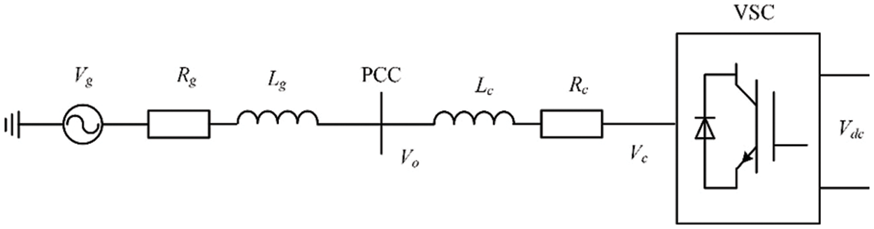
Figure 1: Schematic diagram of VSC-HVDC system structure
In order to realize active and reactive power decoupling, the dynamic process of the system is analyzed in the Synchronous Reference Frame (SRF), and the dynamic relationship of current on the AC side of the converter is:
DC line model depicted is represented by a lumped π-equivalent scheme. The dynamic relationship of the DC side system parameters of the converter is:
where,
2.2 Design of Inner and Outer Loop Controller of Converter
The converter adopts the inner and outer loop control structure, and the outer loop controller is the power loop, which independently controls the active and reactive power components of the converter. The inner loop controller controls the D axis current component and the Q axis current component of the converter, respectively. The overall structure block diagram is shown in Fig. 2. In this paper, the active power and reactive power component control of the outer loop of the converter controller adopts the fixed active and reactive power control mode, and the actual measured values of active power and reactive power,

Figure 2: Overall structure block diagram of inner and outer loop controller of converter
In order to ensure the stability of the measured power value, the first-order inertial filter is used for filtering, and the equation of state of the filter is:
where,
where,
where,
2.3 Active AC Damping Controller
The active AC damping controller can suppress the LC oscillation in the system and improve the stability margin of the system [17–19]. As shown in Fig. 3,
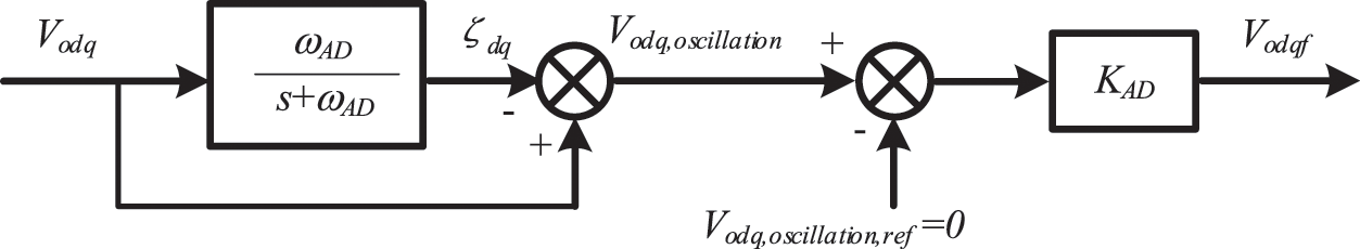
Figure 3: Active AC damping controller
2.4 Active DC Damping Controller
The active DC damping controller is used to suppress the oscillation of the converter, as shown in Fig. 4. Its principle is similar to that of the active AC damping controller. After extraction, the oscillation component is multiplied by the DC gain
where,

Figure 4: Active DC damping controller
In order to accurately track the power grid phase, the design of PLL is based on the SRF [20], as shown in Fig. 5.

Figure 5: Phase-locked loop
The equation of state of the voltage component of DQ axis filtered by the low-pass filter is shown in (14), where
Phase error of voltage component obtained by PI controller
Therefore, the relationship between the output phase of the PLL and the phase of the power grid is:
3 State Space Equations Building
According to the derivation of the mathematical model in Chapter 2, the final formal representation of Eq. (1) is as follows (18)–(20):
The state space equation of the current controller's integrator is
The state equation of reference voltage at PCC is
The state equation of the current flowing to the power grid at PCC is
To sum up, the small signal model of ac system and controller is
where, the state variable X and input variable U are
In order to verify the correctness and validity of the small-signal model of the VSC-HVDC system proposed in this paper, the proposed small-signal model can be implemented in MATLAB and compared with the detailed electromagnetic transient simulation results in PSCAD. Since PSCAD has good electromagnetic transient calculation capability, the accuracy of the small-signal model can be verified if the output of the small-signal model is similar to the model in PSCAD. The main circuit parameters are selected with reference to the parameters of China Yue-Hubei Project, and the system parameters are shown in Table 1.

At

Figure 6: Simulation comparison between electromagnetic transient model and small signal model
4 Analysis of Influence of Control Parameters on System Stability
In order to analyze the influence of control parameters on system stability, they are divided into three categories: (1) internal and external loop parameters; (2) Damper parameters; (3) PLL control parameters. The influences of these three types of parameters on stability are studied in the following paragraphs.
Based on the established small signal model, the eigenvalues of the system can be obtained and the eigenvalues and participation factor analysis can be carried out to determine the main control parts affecting its stability [21–23]. In Table 2, the oscillation frequency, damping rate of all modes of the system and the state variables mainly related to each mode are given.

As shown in Table 2, the system has 21 characteristic roots, which can be divided into 14 groups, corresponding to 14 modes respectively. By analyzing each mode, it can be seen that
4.2 Inner and Outer Loop Control Parameters
4.2.1 Current Control Loop Parameters
The proportional coefficient

Figure 7: Influence of current control loop parameters on eigenvalues (a) The effect of kpc on the eigenvalues λ2–3, λ4–5 (b) The effect of kpc on the eigenvalues λ8–9, λ15–16, (c) The effect of kic on the eigenvalues
As shown in Figs. 7a and 7b, with the increase of
As shown in Fig. 7c, with the increase of
4.2.2 Voltage Outer Loop Parameters
The proportional coefficient
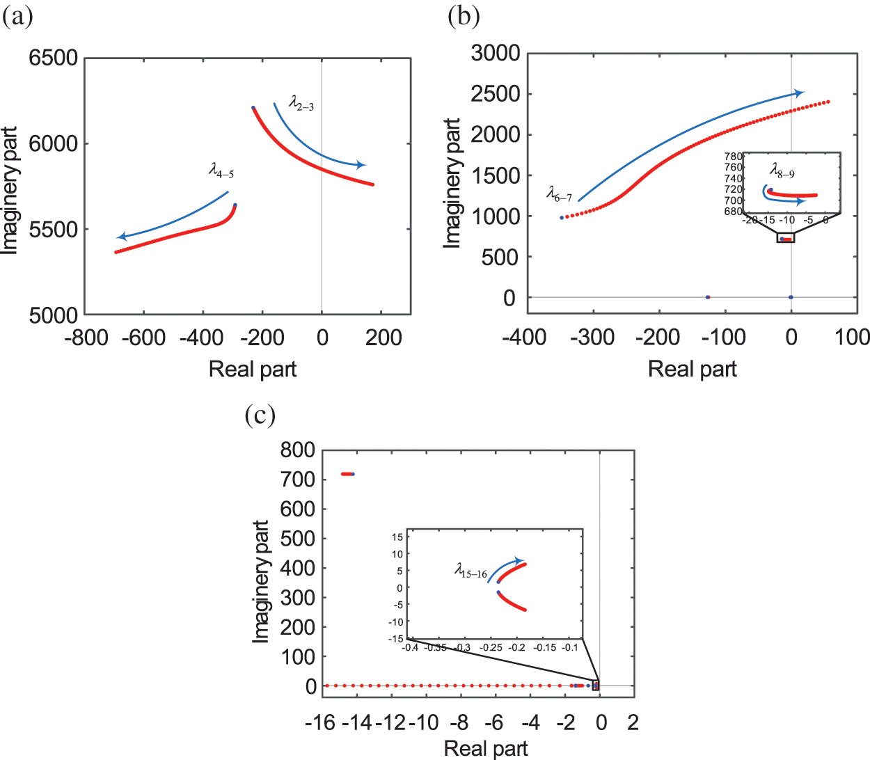
Figure 8: Influence of voltage outer loop parameters on eigenvalues (a) The effect of kpp on the eigenvalues λ2–3, λ4–5, (b) The effect of kpp on the eigenvalues λ6–7, λ8–9 (c) The effect of kip on the eigenvalues
As shown in Figs. 8a and 8b, with the increase of
As shown in Fig. 8c, with the increase of
By changing the filter parameter
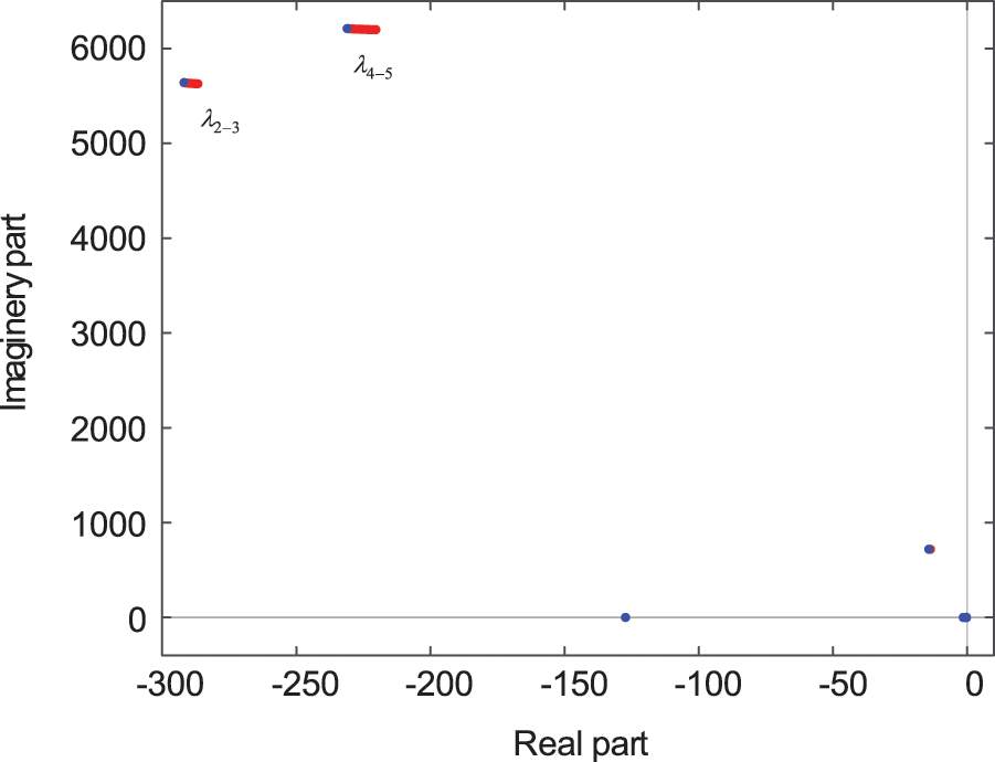
Figure 9: The effect of
As shown in Fig. 9, as
4.3.1 Active AC Damping Controller Parameters
Change the gain

Figure 10: Influence of active AC damping controller parameters on eigenvalues (a) The effect of kAD on the eigenvalues (b) The effect of ωAD on the eigenvalues
As shown in Fig. 10a, with the increase of
As shown in Fig. 10b, with the increase of
4.3.2 Active DC Damping Controller Parameters
The gain

Figure 11: Influence of active DC damping controller parameters on eigenvalues (a) The effect of kAD, dc on the eigenvalues (b) The effect of ωAD,dc on the eigenvalues
As shown in Fig. 11a, with the increase of
As shown in Fig. 11b, with the increase of
The proportional coefficient

Figure 12: Influence of phase locked loop parameters on eigenvalues (a) The effect of kppll on the eigenvalues (b) The effect of kipll on the eigenvalues (c) The effect of ωlp on the eigenvalues
As shown in Fig. 12a, as
As shown in Fig. 12b,
As shown in Fig. 12c, with the increase of
4.5 The Influence of Grid Impedance on Stability
The AC system to which the flexible DC transmission system is connected has multiple modes of operation, which have a large impact on the equivalent impedance on the AC side. The effect of the change in the operating conditions of the AC side of the system on the stability of the system is studied by changing the size of the equivalent inductance.
By changing the filter parameter

Figure 13: The effect of
As shown in Fig. 13, as
4.6 Summary of Influence of Control Parameters on Stability
The analysis shows that the studied characteristic roots may move to the right half plane when the control parameters change, resulting in system instability. Further analysis shows that the rise of
To demonstrate the effect of control parameter optimization on system stability improvement, the system oscillation phenomenon of 139 Hz occurs by changing the grid equivalent impedance and reducing the grid SCR. Now, the oscillation phenomenon caused by the change of grid strength is eliminated by optimizing the control parameters, and the time domain graph is plotted to illustrate the effect of optimization in this paper.
The red dots in the Fig. 14 indicate the distribution of the characteristic roots of the system before optimization. For this operating condition, the blue dots in the figure indicate the distribution of the characteristic roots after the optimization of the control parameters, and the pair of unstable characteristic roots is eliminated, making the system stable. Fig. 15 reflects the variation of active power variation and reactive power variation with time before and after optimization after applying a small disturbance of −5% step change to the active power reference value at 5 s under unstable operating conditions. The images illustrate that the oscillations due to the alternating current side impedance variations are well eliminated and the small-signal stability of the system is enhanced after the parameter optimization.

Figure 14: Distribution of each eigenvalue before and after adjustment

Figure 15: Active power and reactive power changes before and after optimization
This paper focuses on the small-signal stability of VSC-HVDC systems. Firstly, a small-signal model of the system considering additional filtering links, damping controller and AC-DC side interaction characteristics is established. Based on this, the oscillation modes of the system are calculated and the influence of the control parameters on the stability of the system in each frequency band is analyzed. The system stability is improved by optimizing the system control parameters for the grid strength changes caused by the changes in AC-side operating conditions, and the specific conclusions are as follows:
(1) The inner and outer loop PI control scale factors
(2) For the system low frequency oscillation phenomenon, the AC active damper gain
(3) When the AC side of the grid due to fault caused by the change in operating conditions, resulting in system strength changes, may also cause system oscillations. As the AC grid strength decreases, the system small signal stability gradually decreases until destabilization. For this situation, the system stability of this condition can be improved and the oscillation phenomenon can be eliminated by optimizing the key control parameters of the destabilization characteristic root according to the change of the characteristic root trajectory. In the engineering design, it is necessary to consider whether the grid strength changes caused by a variety of possible current grid operating conditions will lead to broadband oscillation problems, and use this to adjust the control parameters.
Funding Statement: The authors thankfully acknowledge the support of the project supported by Research on the Oscillation Mechanism and Suppression Strategy of Yu-E MMC-HVDC Equipment and System (2021Yudian Technology 33#).
Conflicts of Interest: The authors declare that they have no conflicts of interest to report regarding the present study.
References
1. Flourentzou, N., Agelidis, V. G., Demetriades, G. D. (2009). VSC-based HVDC power transmission systems: An overview. IEEE Transactions on Power Electronics, 24(3), 592–602. DOI 10.1109/TPEL.2008.2008441. [Google Scholar] [CrossRef]
2. Wang, X., Blaabjerg, F. (2018). Harmonic stability in power electronic based power systems: Concept, modeling, and analysis. IEEE Transactions on Smart Grid, 10(3), 2858–2870. DOI 10.1109/TSG.2018.2812712. [Google Scholar] [CrossRef]
3. Hannan, M. A., Hussin, I., Ker, P. J., Hoque, M. M., Hossain Lipu, M. S. et al. (2018). Advanced control strategies of VSC based HVDC transmission system: Issues and potential recommendations. IEEE Access, 6, 78352–78369. DOI 10.1109/ACCESS.2018.2885010. [Google Scholar] [CrossRef]
4. Mochamad, R. F., Preece, R. (2020). Assessing the impact of VSC-HVDC on the interdependence of power system dynamic performance in uncertain mixed AC/DC systems. IEEE Transactions on Power Systems, 35(1), 63–74. DOI 10.1109/TPWRS.2019.2914318. [Google Scholar] [CrossRef]
5. Zou, C., Hong, R. G., Xu, S., Yan, L., Bo, L. (2018). Analysis of resonance between a VSC-HVDC converter and the AC grid. IEEE Transactions on Power Electronics, 33(12), 10157–10168. DOI 10.1109/TPEL.2018.2809705. [Google Scholar] [CrossRef]
6. Zhang, Y., Hong, C., Tu, L., Zhou, T., Yang, J. (2018). Research on high-frequency resonance mechanism and active harmonic suppression strategy of power systems with power electronics. International Conference on Power System Technology (POWERCON), pp. 2350–2356. Guangzhou, China. DOI 10.1109/POWERCON.2018.8601628. [Google Scholar] [CrossRef]
7. Guo, C., Yang, S., Liu, W., Zhao, C., Hu, J. (2021). Small-signal stability enhancement approach for VSC-HVDC system under weak AC grid conditions based on single-input single-output transfer function model. IEEE Transactions on Power Delivery, 36(3), 1313–1323. DOI 10.1109/TPWRD.2020.3006485. [Google Scholar] [CrossRef]
8. Huang, Y., Zhai, X., Hu, J., Liu, D., Lin, C. (2018). Modeling and stability analysis of VSC internal voltage in DC-link voltage control timescale. IEEE Journal of Emerging and Selected Topics in Power Electronics, 6(1), 16–28. DOI 10.1109/JESTPE.2017.2715224. [Google Scholar] [CrossRef]
9. Arani, M. F. M., Mohamed, Y. A. I. (2017). Analysis and performance enhancement of vector-controlled VSC in HVDC links connected to very weak grids. IEEE Transactions on Power Systems, 32(1), 684–693. DOI 10.1109/TPWRS.2016.2540959. [Google Scholar] [CrossRef]
10. Pinares, G., Bongiorno, M. (2016). Modeling and analysis of VSC-based HVDC systems for DC network stability studies. IEEE Transactions on Power Delivery, 31(2), 848–856. DOI 10.1109/TPWRD.2015.2455236. [Google Scholar] [CrossRef]
11. Guan, M., Pan, W., Zhang, J., Hao, Q., Cheng, J. et al. (2015). Synchronous generator emulation control strategy for voltage source converter (VSC) stations. IEEE Transactions on Power Systems, 30(6), 3093–3101. DOI 10.1109/TPWRS.2014.2384498. [Google Scholar] [CrossRef]
12. Li, H., Liu, C., Li, G., Iravani, R. (2017). An enhanced DC voltage droop-control for the VSC–HVDC grid. IEEE Transactions on Power Systems, 32(2), 1520–1527. DOI 10.1109/TPWRS.2016.2576901. [Google Scholar] [CrossRef]
13. Xu, L., Sun, M., Xin, H., Song, X., Wang, C. (2019). Influence of power factor on small-signal stability of grid-connected converter systems. 2019 IEEE 8th International Conference on Advanced Power System Automation and Protection (APAP), pp. 878–882. Xi'an, China. DOI 10.1109/APAP47170.2019.9225181. [Google Scholar] [CrossRef]
14. Ding, H., Fan, S., Zhou, J. Z., Zhang, Y., Gole, A. M. (2015). Parametric analysis of the stability of VSC-HVDC converters. 11th IET International Conference on AC and DC Power Transmission, pp. 1–6. Birmingham, UK. DOI 10.1049/cp.2015.0002. [Google Scholar] [CrossRef]
15. Renedo, J., Garcia-Cerrada, A., Rouco, L., Sigrist, L. (2021). Coordinated design of supplementary controllers in VSC-HVDC multi-terminal systems to damp electromechanical oscillations. IEEE Transactions on Power Systems, 36(1), 712–721. DOI 10.1109/TPWRS.2020.3003281. [Google Scholar] [CrossRef]
16. Du, C., Agneholm, E., Olsson, G. (2008). Comparison of different frequency controllers for a VSC-HVDC supplied system. IEEE Transactions on Power Delivery, 23(4), 2224–2232. DOI 10.1109/TPWRD.2008.921130. [Google Scholar] [CrossRef]
17. Raza, A., Xu, D., Li, Y., Su, X., Williams, B. W. et al. (2016). Coordinated operation and control of VSC based multiterminal high voltage DC transmission systems. IEEE Transactions on Sustainable Energy, 7(1), 364–373. DOI 10.1109/TSTE.2015.2497340. [Google Scholar] [CrossRef]
18. Safari Tirtashi, M. R., Samuelsson, O., Svensson, J., Pates, R. (2018). Impedance matching for VSC-HVDC damping controller gain selection. IEEE Transactions on Power Systems, 33(5), 5226–5235. DOI 10.1109/TPWRS.2018.2815153. [Google Scholar] [CrossRef]
19. Du, W., Fu, Q., Wang, H. (2018). Subsynchronous oscillations caused by open-loop modal coupling between VSC-based HVDC line and power system. IEEE Transactions on Power Systems, 33(4), 3664–3677. DOI 10.1109/TPWRS.2017.2771764. [Google Scholar] [CrossRef]
20. Zhou, J. Z., Ding, H., Fan, S., Zhang, Y., Gole, A. M. (2014). Impact of short-circuit ratio and phase-locked-loop parameters on the small-signal behavior of a VSC-HVDC converter. IEEE Transactions on Power Delivery, 29(5), 2287–2296. DOI 10.1109/TPWRD.2014.2330518. [Google Scholar] [CrossRef]
21. Amin, M., Suul, J. A., D'Arco, S., Tedeschi, E., Molinas, M. (2015). Impact of state-space modelling fidelity on the small-signal dynamics of VSC-HVDC systems. 11th IET International Conference on AC and DC Power Transmission, pp. 1–11. Birmingham, UK. DOI 10.1049/cp.2015.0048. [Google Scholar] [CrossRef]
22. Li, Y., Du, Z. (2022). Stabilizing condition of grid-connected VSC as affected by phase locked loop (PLL). IEEE Transactions on Power Delivery, 37(2), 1336–1339. DOI 10.1109/TPWRD.2021.3115976. [Google Scholar] [CrossRef]
23. Urquidez, O. A., Xie, L. (2016). Singular value sensitivity based optimal control of embedded VSC-HVDC for steady-state voltage stability enhancement. IEEE Transactions on Power Systems, 31(1), 216–225. DOI 10.1109/TPWRS.2015.2393253. [Google Scholar] [CrossRef]
Cite This Article
 Copyright © 2023 The Author(s). Published by Tech Science Press.
This work is licensed under a Creative Commons Attribution 4.0 International License , which permits unrestricted use, distribution, and reproduction in any medium, provided the original work is properly cited.
 Downloads
 Citation Tools