
 Submit a Paper
 Propose a Special lssue
 Open Access
ARTICLE

Adaptive Reclosing Scheme Based on Traveling Wave Injection For Multi-Terminal dc Grids
1 State Grid Beijing Electric Power Company, Beijing, 100031, China
2 State Grid Beijing Tongzhou Electric Power Supply Company, Beijing, 101101, China
3 State Key Laboratory of Alternate Electrical Power System with Renewable Energy Sources, North China Electric Power University, Beijing, 102206, China
* Corresponding Author: Peng Han. Email:
Energy Engineering 2023, 120(5), 1271-1285. https://doi.org/10.32604/ee.2023.027489
Received 01 November 2022; Accepted 30 November 2022; Issue published 20 February 2023
 View Full Text
 Download PDF
Abstract
The hybrid dc circuit breaker (HCB) has the advantages of fast action speed and low operating loss, which is an ideal method for fault isolation of multi-terminal dc grids. For multi-terminal dc grids that transmit power through overhead lines, HCBs are required to have reclosing capability due to the high fault probability and the fact that most of the faults are temporary faults. To avoid the secondary fault strike and equipment damage that may be caused by the reclosing of the HCB when the permanent fault occurs, an adaptive reclosing scheme based on traveling wave injection is proposed in this paper. The scheme injects traveling wave signal into the fault dc line through the additionally configured auxiliary discharge branch in the HCB, and then uses the reflection characteristic of the traveling wave signal on the dc line to identify temporary and permanent faults, to be able to realize fast reclosing when the temporary fault occurs and reliably avoid reclosing after the permanent fault occurs. The test results in the simulation model of the four-terminal dc grid show that the proposed adaptive reclosing scheme can quickly and reliably identify temporary and permanent faults, greatly shorten the power outage time of temporary faults. In addition, it has the advantages of easiness to implement, high reliability, robustness to high-resistance fault and no dead zone, etc.Keywords
Since the multi-terminal dc (MTdc) grid has the advantages of decoupled active and reactive power control, ability to supply power for passive networks, etc., it has been a research hotspot worldwide [1,2]. With the increasing demand for long-distance power transmission and large-scale integration of renewable energy sources, overhead lines with dc circuit breakers (DCCBs) will be the mainstream transmission method for large-scale MTdc grids in the future [3,4].
The currently proposed DCCBs are mainly divided into three categories, namely mechanical DCCBs, solid-state DCCBs and hybrid dc circuit breakers (HCBs) [5–8]. Among them, the HCB combines the advantages of mechanical DCCB and solid-state DCCB, which has low operating loss and fast action speed. Therefore, the HCB is considered as one of the preferred methods for fault isolation of MTdc grids.
Compared with dc cables, overhead lines have significantly higher fault probability due to direct exposure to air, and most of these faults are temporary faults. In the ac system, the ac circuit breaker is usually equipped with auto-reclosing function to try to quickly restore the power supply of the fault line, and there is a very high probability of successful reclosing (60%~90%) [9–11]. Therefore, the MTdc grid based on overhead lines can also be equipped with auto-reclosing for DCCB to shorten the power outage time. At present, the HCB in the MTdc grid usually adopts non-selective reclosing function, that is, after the HCB interrupts the fault current, it waits for a certain de-ionization time (about several hundreds of milliseconds) and then directly recloses [12]. If the fault current rises rapidly after the HCB recloses, the HCB will be controlled to re-interrupt the fault current and will not reclose anymore. Therefore, if the HCB recloses after the permanent fault occurs, the MTdc grid will suffer two consecutive fault strikes in a short period, which will reduce the service life of vulnerable equipment such as DCCBs and converters, and even cause them to be damaged [13]. For MTdc grids, due to its low impedance characteristic and the fragility of power electronic equipment, the impact of multiple fault strikes in a short period is much greater than that of ac systems [14].
In order to prevent the HCB from reclosing on a permanent fault, the fault type must be identified before the reclosing operation, that is, whether the fault is a temporary fault or a permanent fault. Since the fault type is identified before reclosing, it is named as adaptive reclosing. In ac systems, adaptive reclosing methods mostly utilize the recovery voltage generated by the coupling effect between the fault and healthy phases to distinguish temporary and permanent faults [15,16]. However, there is no coupling between different poles of the dc line, so the above method is no longer applicable. Reference [17] proposed an adaptive reclosing scheme based on arc characteristics for single-phase ground faults in ac systems. Due to the large difference in ac and dc arc characteristics, this scheme is difficult to apply to MTdc grids. References [18,19] proposed the reclosing schemes based on the sequential turning-on of the submodules (SMs) in the HCB. The fault type can be determined by comparing the measured current and the threshold current during the turning-on process. If the measured current is greater than the threshold value during the reclosing process, it is determined that a permanent fault has occurred, and the HCB is re-tripped to interrupt the fault current. The control process of this scheme is relatively complicated, and it will lead to uneven energy consumption of the arresters, thereby reducing the arrester service life. Reference [20] proposed an adaptive reclosing scheme based on the pulse injection of the modular multilevel converter (MMC), which is complex and easily affected by adjacent line parameters. Reference [21] first proposed a new type of mechanical DCCB, and then presents a adaptive reclosing scheme for the proposed circuit breaker.
In conclusion, the existing adaptive reclosing schemes cannot meet the requirements of MTdc grids. Therefore, an adaptive reclosing scheme based on traveling wave injection is proposed for MTdc grids in this paper. Firstly, the basic topology and working principle of HCB is introduced; Then, the auxiliary discharge switch (ADS) of HCB and the corresponding fault type identification method are proposed, and a complete adaptive reclosing scheme is further presented. Finally, the effectiveness of the proposed adaptive reclosing scheme is verified by the four-terminal dc grid simulation model built in PSCAD/EMTDC software.
The topology of the typical HCB is shown in Fig. 1, which includes three parallel branches, namely the load current branch (LCP), the transfer branch (TB), and the energy dissipation branch (EDB). Among them, the LCP is a series branch of a load commutation switch (LCS) and an ultrafast disconnector (UFD), which is responsible for conducting the load current during normal operation and quickly force the fault current into the TB. Since the withstand voltage of the LCS is relatively small, it is usually composed of only several insulated gate bipolar transistor (IGBT) modules. The UFD is specially designed to operate for a very short time (approximately 2 ms) at zero current state [22–24]. The TB is composed of many IGBT modules in series and parallel, which is the most expensive part of the HCB. The main function of the TB is to carry the fault current transferred by the LCP for a short time and force the fault current into the EDB. After that, the TB needs to withstand the transient interruption voltage (TIV) much higher than the rated voltage of the system. The EDB is composed of many metal oxide varistors (MOVs) connected in series and parallel, which is mainly responsible for dissipating the energy of the fault current and limiting the amplitude of the TIV.
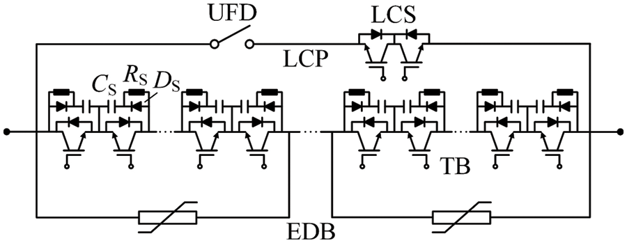
Figure 1: Topology of the HCB
Fig. 2 shows a schematic diagram of the current and voltage waveforms of each branch during the operation of the HCB. The detailed operation process of the HCB is as follows.
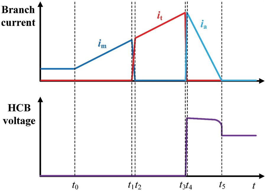
Figure 2: Operation waveforms of the HCB
A short-circuit fault occurs at time t0, and the fault current flowing through the HCB begins to rise rapidly. The HCB receives the trip command at time t1 and starts to operate. First, the SMs in the TB are turned on, and the LCS in the LCP is opened. The fault current begins to commutate from the LCP to the TB. The LCP current drops to zero at time t2, at this time, the UFD starts to open. After the action time of 2 ms, the UFD is successfully opened at time t3, and the SMs in the TB are all turned off. In the TB, in order to suppress the turn-off voltage amplitude and du/dt of the modules, an RCD snubber circuit (including a snubber diode DS, a snubber capacitor CS and a snubber resistor RS) is usually connected in parallel of each IGBT module, as shown in Fig. 1. After the SMs in the TB is turned off, the fault current will first charge the snubber capacitor CS through the snubber diode DS in the snubber circuit, as shown in Fig. 2. As the snubber capacitor voltage increases (t3 < t < t4), the fault current will gradually be forced into the EDB. At time t4, the fault current is fully commutated to the EDB, and the fault current begins to decrease gradually at this time due to the TIV generated by the MOVs. After the fault current drops to zero at time t5, the operation of the HCB is finished.
It can be seen from the above analysis and Fig. 2 that after the HCB operation is completed, the potential on the dc line side is clamped to nearly zero by the fault point and the potential on the bus side is the same as the grid potential, so the HCB needs to withstand the rated grid voltage. This voltage is shared by all the snubber capacitors in the TB. Therefore, the voltage USC of the snubber capacitor in each IGBT module is as follows:
where Udc is the rated grid voltage, N is the number of SMs in the TB. Since each SM in the TB is composed of two IGBT modules connected in reverse direction, only one snubber capacitor in each SM is in the charged state during the fault current interruption.
Since the snubber capacitor of each SM in the TB keep its voltage after the HCB action is completed, the stored energy can be used to determine the fault type. To achieve this purpose, an additional ADS is configured for HCB, and its configuration position is illustrated in Fig. 3. The LCP and EDB of HCB have been omitted in Fig. 3. The ADS can use conventional ac circuit breaker for convenient, which is installed on the left side of ND SMs near the line side in the TB.
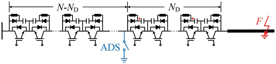
Figure 3: Configuration of the ADS
3.2 Fault Type Identification Principle
3.2.1 Travelling Wave Injection Process
After the HCB interrupts the fault current and waits for the line de-ionization time, the ADS is first closed. At this time, the snubber capacitors of the line-side ND SMs in the TB will be rapidly discharged. The discharge path is shown in Fig. 4. This process is equivalent to injecting traveling wave signal into the dc line, and its equivalent calculation circuit is shown in Fig. 5.
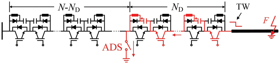
Figure 4: Current path during the discharge process
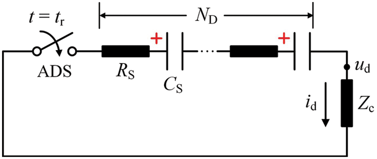
Figure 5: Equivalent calculation circuit
From Fig. 5, the injected traveling wave signal can be expressed as:
where Zc is the wave impedance of the dc line. It can be seen from Eq. (2) that the polarity of the injected traveling wave signal is only related to the fault pole where the HCB is located. When the HCB is on the positive line, Udc is greater than zero, and the injected traveling wave signal is negative; and when the HCB is on the negative line, Udc is less than zero, and the injected traveling wave signal is positive.
As can be seen in Eq. (2), the amplitude of the injected traveling wave signal is proportional to the number ND of the discharged SMs. With the increase of the discharged SMs, the amplitude of the injected signal becomes larger, which is more conducive to the fault type identification. However, this will also generate larger disturbance to the rest healthy networks. Therefore, under the premise of meeting the fault type identification requirements, the number ND of the discharged SMs should be as small as possible to avoid disturbance. Therefore, considering the above trade-off relationship, the number ND of the discharged SMs is selected as 10% of the total number N of the SMs, which can guarantee enough identification sensitivity while avoid large disturbance to the rest healthy networks.
3.2.2 Transmission Characteristic of Travelling Wave
After the traveling wave signal TWin is injected into the dc line by the HCB, it will propagate to the opposite terminal along the dc line, and will be reflected at the discontinuous point of the wave impedance, as shown in Fig. 6. Assuming that the fault is a temporary fault and has disappeared at this time, the injected traveling wave signal TWin will be reflected at the opposite line terminal first and the reflected wave will be TWre2; and when the fault is a permanent fault, the injected traveling wave signal will be reflected at the fault point first and the reflected wave will be TWre1. The following will analyze the reflection characteristics of the traveling wave signal at the line terminal and the fault point.
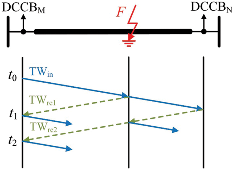
Figure 6: Transmission process schematic of traveling wave
According to the traveling wave theory, the current traveling wave reflection coefficient is:
where Z1 is the wave impedance of the conductor where the traveling wave is propagating, Z2 is the wave impedance of the conductor that the traveling wave will enter. Therefore, for the fault point, the traveling wave reflection coefficient is:
where Rf is the fault resistance. For the line port, since the HCB has acted to isolate the fault, Z2 is equivalent to infinity, and the traveling wave reflection coefficient can be approximately −1 from Eq. (3). Since the reflection coefficient of the traveling wave at the fault point is greater than zero, the polarities of the reflected wave and the injected traveling wave signal are the same; while the reflection coefficient of the traveling wave at the line port is less than zero, the polarities of the reflected wave and the injected wave signal are opposite. Due to the difference in polarity of reflected traveling waves during temporary and permanent faults, the polarity of reflected traveling wave can be used to identify the fault type.
Based on the above analysis, if the polarity of the first reflected wave detected at the HCB is opposite to the injected traveling wave signal, the fault type of the dc line is determined as temporary fault; if the first reflected wave detected at the HCB is the same as the injected traveling wave signal, the fault type of the dc line is determined as permanent fault.
3.3 Fault Type Identification Criteria
Wavelet transform is an excellent time-frequency analysis tool for digital signal processing and is widely used in fault traveling wave analysis. Mallat algorithm is a commonly used discrete wavelet transform, which realizes fast calculation through a series of filtering and binary sampling. The basic principle of Mallat algorithm is as follows:
where a0(k) is the original analysis signal; h0 and h1 are the low-pass and high-pass filters, respectively; aj(k) and dj(k) are the low-frequency and high-frequency coefficients of the jth scale, respectively; fs is the signal sampling frequency. Compared with the specific frequency coefficient, the wavelet transform maximum (WTMM) is a more concise way of representing signal characteristics. The magnitude and symbol of the WTMM can approximately represent the amplitude and polarity of the analyzed signal in different frequency bands. Therefore, the WTMM is selected to determine the polarity of traveling wave signal in this paper. If the WTMM satisfies Eq. (6), it is determined that the traveling wave signal is positive; and if the WTMM satisfies Eq. (7), it is determined that the traveling wave signal is negative.
where WTMMset is the threshold to avoid the influence of the noise interference.
Since the traveling wave signal is injected into the dc line and the first reflected wave reaches the HCB, the polarity of the WTMM will change. Therefore, when the maximum value of the first and second WTMMs satisfy Eqs. (6) or (7), the fault type can be determined. From the analysis in Section 3.2, if the polarities of the first and second WTMMs are the same, indicating that the polarities of the first reflected wave and the injected traveling wave signal are the same, the fault type will be determined as permanent fault; and if the polarities of the first and second WTMMs are opposite, indicating that the reflected wave and the injected traveling wave signal have opposite polarities, the fault type will be determined as permanent fault.
3.4 Flowchart of Fault Type Identification
According to the analysis in Sections 3.2 and 3.3, the flowchart of the fault type identification is illustrated in Fig. 7.
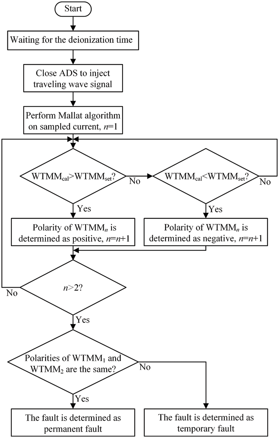
Figure 7: Flowchart of the fault type identification
3.5 Operation Sequences of Adaptive Reclosing Scheme
Based on the above analysis, the complete sequences of the adaptive reclosing scheme are illustrated by taking the dc line MN (the HCBs at both ends are named HCBM and HCBN, respectively) as an example, as follows:
Step 1: After the HCBM and HCBN interrupt the fault current, assuming that the traveling wave signal is injected by the HCBM, the disconnector at the HCBN side is opened.
Step 2: After waiting for the line de-ionization time, the ADS of the HCBM is closed, and the traveling wave signal will be injected into the fault line by the HCBM.
Step 3: After the traveling wave signal is injected, the measurement unit on the HCBM side measures the line current, and uses the fault type identification criteria in Section 3.3 to determine the fault type of the dc line. If the fault type is determined as temporary fault, go to Step 4, otherwise go to Step 5.
Step 4: The ADS of the HCBM is opened, then the SMs in the TB are all turned on, and the dc line voltage begins to rise. After the HCBN detects that the dc line voltage rises to close to the rated value, the SMs in the TB of the HCBN are all turned on, and the load current begins to gradually recover. After that, the HCBs on both terminals close the LCS and the UFD in turn. After that, the reclosing operation is successful, and the fault line has been put into operation again.
Step 5: The disconnector on the HCBM side is opened. The reclosing operation is failed, and the HCBs on both sides will no longer reclosed.
In order to verify the performance of the adaptive reclosing scheme proposed in this paper, a four-terminal dc grid simulation model is built in PSCAD/EMTDC software. The schematic diagram and main parameter settings are shown in Fig. 8 and Table 1, respectively. The sampling frequency required for the adaptive reclosing scheme is 10 kHz. The lengths of Line 1, Line 2, Line 4 and Line 4 are 205.9, 188.1, 49.6 and 208.4 km, respectively. The line de-ionization time is set to 300 ms. The action time of ADS, UFD and disconnector is set to 2, 2 and 30 ms, respectively. The number N of the SMs in the TB of the HCB is 300, and the number of discharged SMs ND is 10% of the total number of SMs, that is, 30. The identification threshold WTMMset in Eqs. (6) and (7) is set to 0.02.
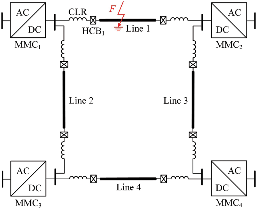
Figure 8: Schematic of the four-terminal dc grid
4.2 Typical Permanent Fault Analysis
A short-circuit fault is set at the midpoint of Line 1 at 4.0 s, and the fault duration is set to 10.0 s to simulate a permanent fault. The HCBs at both ends of Line 1 operate at 4.003 s, the HCB1 starts the operation of adaptive reclosing at 4.3 s. The ADS closes at 4.302 s, and the traveling wave signal is injected into Line 1 by HCB1. The simulation waveforms during the adaptive reclosing process are shown in Figs. 9 and 10.
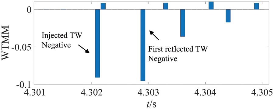
Figure 9: WTMM waveform under permanent fault
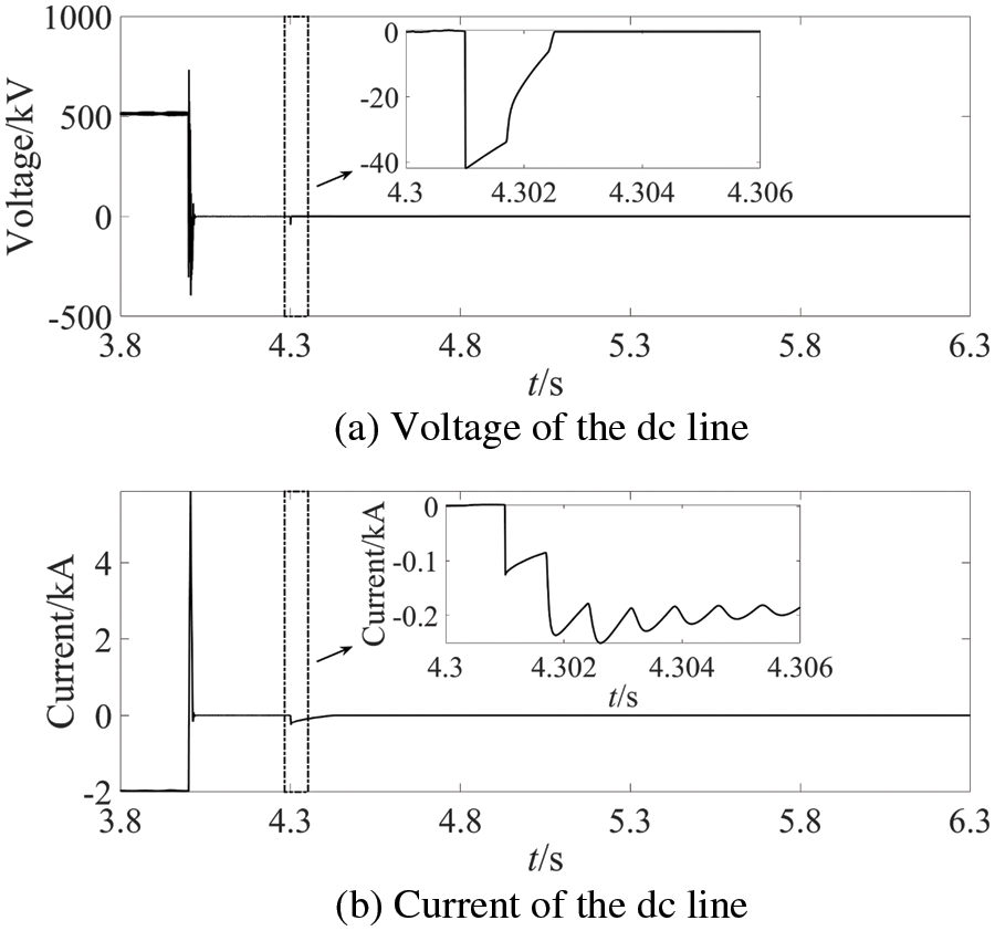
Figure 10: Waveforms of the dc line electrical quantities under permanent fault
It can be seen from Fig. 9 that the polarities of the first and second WTMMs are the same. Therefore, from Section 3.3, the fault is determined as a permanent fault, and the HCBs will no longer be reclosed. As can be seen from Fig. 10, in the process of adaptive reclosing, even if a permanent fault occurs, it will not affect the normal operation of the MTdc grid.
4.3 Typical Temporary Fault Analysis
A short-circuit fault is set at the midpoint of Line 1 at 4.0 s, and the fault duration is set to 0.3 s to simulate a temporary fault. The HCBs at both ends of Line 1 operate at 4.003 s, the HCB1 starts the operation of adaptive reclosing at 4.3 s. The ADS closes at 4.302 s, and the traveling wave signal is injected into Line 1 by HCB1. The simulation waveforms during the adaptive reclosing process are shown in Figs. 11 and 12.
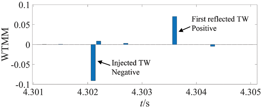
Figure 11: WTMM waveform under temporary fault
Figure 12: Waveforms of the dc line electrical quantities under temporary fault
It can be seen from Fig. 11 that the polarities of the first and second WTMMs are opposite, so from Section 3.3, the fault that occurs is determined as a temporary fault. Therefore, the HCBs will continue to reclose, as described in Section 3.5. As can be seen from Fig. 12, in the process of adaptive reclosing, if the fault is a temporary fault, the power supply of the dc line can be quickly restored, thereby significantly improving the reliability of the dc grid power supply.
4.4 Influencing Factor Analysis
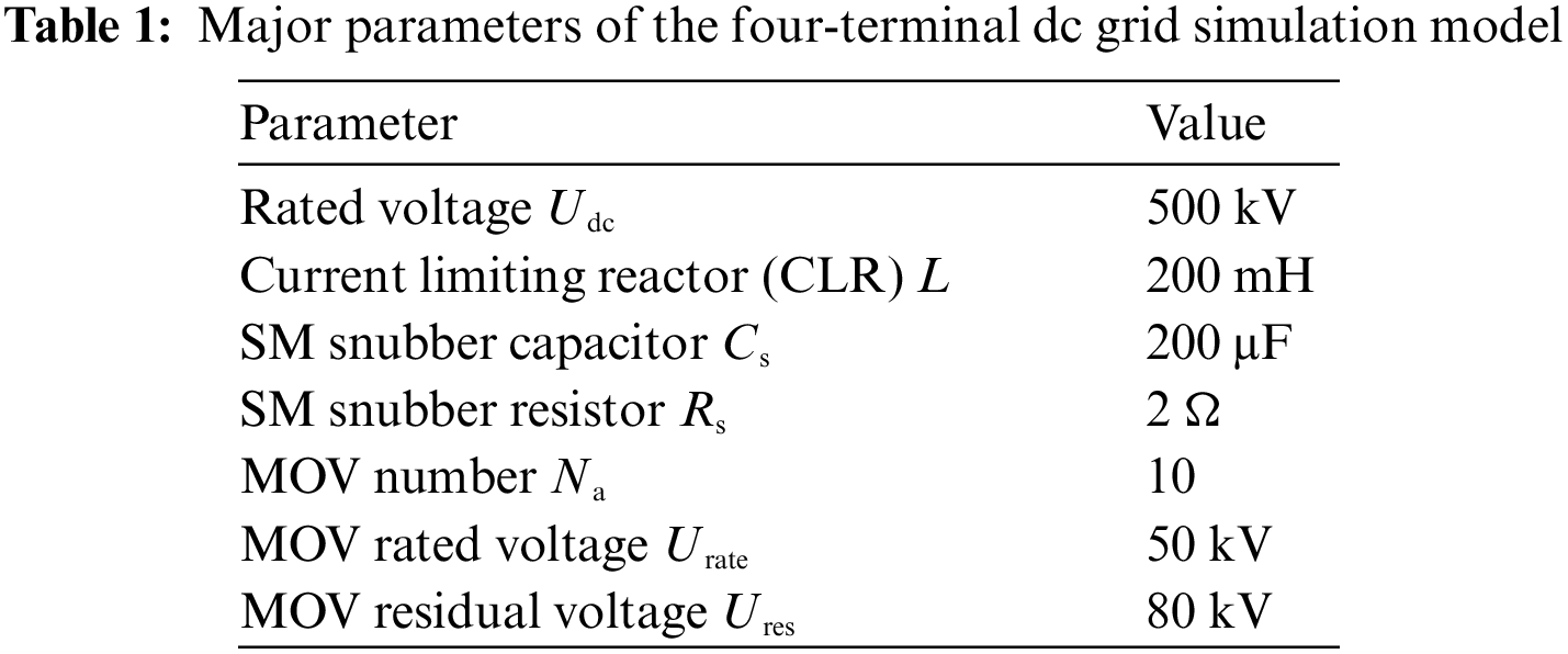
In order to verify the influence of the fault location on the adaptive reclosing scheme proposed in this paper, two short-circuit faults were set at 20.59 km (10% of the full length of Line 1) and 185.31 km (90% of the full length of Line 1) from MMC1 on the dc line 1 at 4.0 s, respectively. The fault durations are both set to 10 s to simulate permanent faults. The HCBs at both ends of Line 1 operates at 4.003 s, then HCB1 starts the operation of the adaptive reclosing at 4.3 s. The ADS closes at 4.302 s, and the traveling wave signal is injected into Line 1 by HCB1. The waveforms of WTMM at different fault locations are shown in Fig. 13.
Figure 13: WTMM waveform under different fault locations
It can be seen from Fig. 13 that the polarities of the first and second WTMMs are the same, so from Section 3.3, the fault is determined as a permanent fault, which is the same as the fault setting. Therefore, for both close-in and remote faults, the adaptive reclosing scheme proposed in this paper can reliably identify the fault type.
In order to verify the effect of transition resistance on the adaptive reclosing scheme proposed in this paper, a short-circuit fault is set at the midpoint of Line 1 at 4.0 s, the fault resistance is 300
Figure 14: WTMM waveform under high-resistance fault
It can be seen from Fig. 14 that the polarities of the first and second WTMMs are the same, so the fault is determined as a permanent fault, which is the same as the fault setting. Therefore, for high-resistance faults, the adaptive reclosing scheme proposed in this paper can still reliably identify the fault type.
In order to verify the influence of the noise interference on the adaptive reclosing scheme proposed in this paper, the Gaussian white noise of 40 dB is superimposed on the simulated currents in Sections 4.2 and 4.3. The waveforms of calculated WTMM of the noise-superimposed currents are shown in Fig. 15. As can be seen, the first and the second WTMMs has the same polarities when the permanent fault occurs, while the first and the second WTMMs has the opposite polarities after the temporary fault occurs, which is consistent with the theory analysis in Section 3.3. Since the wavelet transform based on Mallat algorithm has de-noise capability, the noises can hardly affect the operation of the proposed method.
Figure 15: WTMM waveform under noise interference
4.4.4 Current Limiting Reactor
As can be seen in Fig. 4, the current path during the snubber capacitors discharge will not include the CLR, which indicates that the CLR will not influence the traveling wave signal injection process. Besides, during the traveling wave signal transmission, since the HCB on the remote terminal of the line has tripped, the traveling wave reflection coefficient will always be −1 whether the value of the CLR is. In conclusion, the CLRs on the line terminals will not affect the proposed fault type identification method.
4.5 Comparison of Existing Solutions
In [25], the signal injection is realized by a modified snubber circuit, named as RCT snubber circuit. Compared to the traditional RCD snubber circuit, the RCT snubber circuit adopts a snubber thyristor to replace the snubber diode, which introduces substantial additional costs and makes the operation process of HCB become more complex. In addition, the control circuit of the RCT snubber circuit will reduce the reliability of the HCB. As for the proposed solution in this paper, it only needs an additional mechanical switch and will not affect the fault current interruption process of the HCB.
In [26,27], the adaptive reclosing schemes based on the characteristic signal injected by hybrid MMC are proposed. Since these methods are only suitable for MTdc grid with specific type of converters, their applications are greatly limited. The adaptive reclosing scheme in [20] realizes the fault type identification by the characteristic signal injected by the MMC. Since the signal is injected from the source side, it will not only transmit in the fault line, but transmit in the adjacent healthy lines. Therefore, the reflected signals from other dc lines may lead to the maloperation of the fault type identification results. As for the proposed solution in this paper, since it injects signal from the line side, it will not be influenced by adjacent lines. Besides, it has no limitation on the converters in the MTdc grid, which has wide application prospect.
In [18,19], the adaptive reclosing scheme based on sequential turning on the SMs in the HCB is proposed. However, after the permanent fault occurs, the HCB should be re-tripped to interrupt the fault current, which will lead to the uneven energy dissipation between the MOVs and further cause the accelerated degradation and reduced life of the MOVs. As for the proposed solution in this paper, only small disturbance will be generated and the HCB will not be re-tripped even permanent fault occurs, which ensures the normal operation of the healthy networks and avoids the damage of the MOVs in the HCB.
In order to avoid the fault impact and damage of fragile equipment that may be caused by HCB non-selective reclosing, this paper proposes an adaptive reclosing scheme based on traveling wave injection of the HCB. The scheme utilizes the additionally configured ADS in the HCB to inject traveling wave signal into the fault dc line, and uses the reflection characteristic of the traveling wave signal on the dc line to distinguish temporary and permanent faults. The scheme has fast action speed, high sensitivity, low cost, and is easy to implement, and the action process is basically not affected by factors such as fault location and transition resistance.
Funding Statement: This work was supported by the Science and Technology Project of State Grid Corporation of China under Grant 520201210025.
Conflicts of Interest: The authors declare that they have no conflicts of interest to report regarding the present study.
References
1. Abedrabbo, M., Dejene, F. Z., Leterme, W., Hertem, D. V. (2021). HVDC grid post-DC fault recovery enhancement. IEEE Transactions on Power Delivery, 36(2), 1137–1148. DOI 10.1109/TPWRD.2020.3002717. [Google Scholar] [CrossRef]
2. Bimenyimana, S., Wang, C., Asemota, G. N. O., Nduwamungu, A., Mulolani, F. et al. (2022). Fault ride-through (FRT) behavior in VSC-HVDC as key enabler of transmission systems using SCADA viewer software. Energy Engineering, 119(6), 2369–2406. DOI 10.32604/ee.2022.019257. [Google Scholar] [CrossRef]
3. Huang, L., Zhang, Q., Liu, W., Liu, R. (2022). A fault current limiting hybrid DC circuit breaker. Energy Engineering, 119(2), 621–636. DOI 10.32604/ee.2022.016769. [Google Scholar] [CrossRef]
4. Adam, G. P., Ahmed, K. H., Finney, S. J., Bell, K., Williams, B. W. (2013). New breed of network fault-tolerant voltage-source-converter HVDC transmission system. IEEE Transactions on Power Systems, 28(1), 335–346. DOI 10.1109/TPWRS.2012.2199337. [Google Scholar] [CrossRef]
5. Mohammadi, F., Rouzbehi, K., Hajian, M., Niayesh, K., Gharehpetian, G. B. et al. (2021). HVDC circuit breakers: A comprehensive review. IEEE Transactions on Power Electronics, 36(12), 13726–13739. DOI 10.1109/TPEL.2021.3073895. [Google Scholar] [CrossRef]
6. Franck, C. M. (2011). HVDC circuit breakers: A review identifying future research needs. IEEE Transactions on Power Delivery, 26(2), 998–1007. DOI 10.1109/TPWRD.2010.2095889. [Google Scholar] [CrossRef]
7. Liu, Z., Mirhosseini, S., Liu, L., Popov, M., Ma, K. et al. (2022). A contribution to the development of high-voltage dc circuit breaker technologies: A review of new considerations. IEEE Industrial Electronics Magazine, 16(1), 42–59. DOI 10.1109/MIE.2021.3085998. [Google Scholar] [CrossRef]
8. Barnes, M., Vilchis-Rodriguez, D. S., Pei, X., Shuttleworth, R., Cwikowski, O. et al. (2020). HVDC circuit breakers–A review. IEEE Access, 8, 211829–211848. DOI 10.1109/ACCESS.2020.3039921. [Google Scholar] [CrossRef]
9. Dias, O., Magrin, F., Tavares, M. C. (2017). Comparison of secondary arcs for reclosing applications. IEEE Transactions on Dielectrics and Electrical Insulation, 24(3), 1592–1599. DOI 10.1109/TDEI.2017.006188. [Google Scholar] [CrossRef]
10. Xie, C., Li, F. (2020). Adaptive comprehensive auto-reclosing scheme for shunt reactor-compensated transmission lines. IEEE Transactions on Power Delivery, 35(5), 2149–2158. DOI 10.1109/TPWRD.2019.2961981. [Google Scholar] [CrossRef]
11. Mehdi, A., Kim, C. H., Hussain, A., Kim, J. S., Hassan, S. J. U. (2021). A comprehensive review of auto-reclosing schemes in AC, DC, and hybrid (AC/DC) transmission lines. IEEE Access, 9, 74325–74342. DOI 10.1109/ACCESS.2021.3077938. [Google Scholar] [CrossRef]
12. Ding, X., Tang, G., Han, M., Gao, C., Wang, G. (2018). Characteristic parameters extraction and application of the hybrid DC circuit breaker in MMC-HVDC. Proceedings of the CSEE, 38(1), 309–319+369. [Google Scholar]
13. Li, B., He, J., Li, Y., Hong, C., Zhang, Y. (2018). A novel restart control strategy for the MMC-based HVDC transmission system. International Journal of Electrical Power & Energy Systems, 99(4), 465–473. DOI 10.1016/j.ijepes.2018.01.050. [Google Scholar] [CrossRef]
14. Xiang, W., Yang, S., Adam, G. P., Zhang, H., Zuo, W. et al. (2021). DC fault protection algorithms of MMC HVDC grids: Fault analysis, methodologies, experimental validations and future trends. IEEE Transactions on Power Electronics, 36(10), 11245–11264. DOI 10.1109/TPEL.2021.3071184. [Google Scholar] [CrossRef]
15. Shim, J. W., Nam, T., Kim, S., Hur, K. (2013). On the reclose operation of superconducting fault current controller for smart power grid with increasing DG. IEEE Transactions on Applied Superconductivity, 23(3), 5603004. DOI 10.1109/TASC.2012.2235115. [Google Scholar] [CrossRef]
16. Shah, P. H., Bhalja, B. R. (2014). New adaptive digital relaying scheme to tackle recloser-fuse miscoordination during distributed generation interconnections. IET Generation, Transmission & Distribution, 8(4), 682–688. DOI 10.1049/iet-gtd.2013.0222. [Google Scholar] [CrossRef]
17. Dias, O., Tavares, M. C. (2017). Implementation and performance evaluation of a harmonic filter for use in adaptive single-phase reclosing. IET Generation, Transmission & Distribution, 11(9), 2261–2268. DOI 10.1049/iet-gtd.2016.1630. [Google Scholar] [CrossRef]
18. Zhang, S., An, T., Pei, X., Yang, J., Pang, H. et al. (2019). Reclosing strategy for hybrid DC circuit breakers. Automation of Electric Power Systems, 43(6), 129–136. [Google Scholar]
19. Fan, X., Zhang, B. (2019). DC line soft reclosing sequence for HVDC grid based on hybrid DC breaker. The Journal of Engineering, 2019(16), 1095–1099. DOI 10.1049/joe.2018.8432. [Google Scholar] [CrossRef]
20. Yang, S., Xiang, W., Lu, X., Zuo, W., Wen, J. (2020). An adaptive reclosing strategy for MMC-HVDC systems with hybrid DC circuit breakers. IEEE Transactions on Power Delivery, 35(3), 1111–1123. DOI 10.1109/TPWRD.2019.2935311. [Google Scholar] [CrossRef]
21. Wen, W., Liu, H., Li, B., Li, B., Li, P. et al. (2020). Novel reclosing strategy based on transient operating voltage in pseudo-bipolar DC system with mechanical DCCB. IEEE Transactions on Power Electronics, 36(4), 4125–4133. DOI 10.1109/TPEL.2020.3022070. [Google Scholar] [CrossRef]
22. Wen, W., Li, B., Li, B., Wang, Y., Huang, Y. et al. (2019). No-load dielectric recovery of the ultra-fast vacuum switch in hybrid DC circuit breaker. IEEE Transactions on Power Delivery, 34(3), 840–847. DOI 10.1109/TPWRD.2018.2881764. [Google Scholar] [CrossRef]
23. Wen, W., Huang, Y., Al-Dweikat, M., Zhang, Z., Cheng, T. et al. (2015). Research on operating mechanism for ultra-fast 40.5-kV vacuum switches. IEEE Transactions on Power Delivery, 30(6), 2553–2560. DOI 10.1109/TPWRD.2015.2409122. [Google Scholar] [CrossRef]
24. Sim, M. S., Bukhari, S. S. H., Ro, J. S. (2022). Analysis and design of a Thomson coil actuator system for an HVDC circuit breaker. IEEE Access, 10, 58354–58359. DOI 10.1109/ACCESS.2022.3178724. [Google Scholar] [CrossRef]
25. Zhang, D., Yang, Y., Liang, C., Li, M., Liu, Y. et al. (2022). Adaptive reclosing scheme for flexible DC power grid based on improved DC circuit breaker injecting signal. Automation of Electric Power Systems, 46(8), 123–132. [Google Scholar]
26. Cai, P., Xiang, W., Zhou, M., Ni, B., Wen, J. (2020). Research on adaptive reclosing of DC fault based on active signal injected by hybrid MMC. Proceedings of the CSEE, 40(12), 3867–3878. [Google Scholar]
27. Cai, P., Xiang, W., Zhou, M., Ni, B., Zhou, M. et al. (2020). An improved adaptive reclosing strategy of four-terminal flexible DC grid with hybrid modular multilevel converter. Automation of Electric Power Systems, 44(22), 87–93. [Google Scholar]
Cite This Article
 Copyright © 2023 The Author(s). Published by Tech Science Press.
This work is licensed under a Creative Commons Attribution 4.0 International License , which permits unrestricted use, distribution, and reproduction in any medium, provided the original work is properly cited.
 Downloads
 Citation Tools