
 Submit a Paper
 Propose a Special lssue
 Open Access
ARTICLE

Simulation Analysis of Flue Gas Waste Heat Utilization Retrofit Based on ORC System
1 College of Energy and Mechanical Engineering, Shanghai University of Electric Power, Shanghai, 200090, China
2 Shanghai Engineering Research Center of Energy-Saving in Heat Exchange Systems, Shanghai, 200090, China
3 China Huadian Corporation Ltd. Shang Hai Company, Shanghai, 200126, China
4 Zaozhuang Vocational College, Chemical and Pharmaceutical Institute, Zaozhuang, 277000, China
* Corresponding Author: Jiang Liu. Email:
Energy Engineering 2023, 120(8), 1919-1938. https://doi.org/10.32604/ee.2023.027546
Received 03 November 2022; Accepted 17 February 2023; Issue published 05 June 2023
 View Full Text
 Download PDF
Abstract
Recovery of waste heat from boiler flue gas is an effective way to improve energy utilization efficiency. Taking a heating station heating project as an example, the existing heating system of this heating station was analyzed for its underutilized flue gas waste heat and low energy utilization rate. Rankine cycle is an effective waste heat recovery method, and a steam boiler organic Rankine cycle (ORC) cogeneration waste heat utilization method is proposed. The system model simulation is constructed and verified. First, a thermodynamic model was constructed in MATLAB and five suitable work gases were selected to analyze the effects of evaporation temperature and condensation temperature on the network and thermal efficiency of the waste heat cycle power system. Secondly, the ORC model is invoked in TRNSYS to construct the improved cogeneration system, and the rationality of the remaining heat utilization methods is determined by calculating and analyzing the thermal performance, economy, and environmental protection of the improved system. The simulation results show that the system can generate about 552,000 kWh of electricity per year, and improving the energy utilization rate from 0.72 to 0.78.Graphic Abstract
Keywords
Nomenclature
| ORC | Organic Rankine Cycle |
| SRC | Steam Rankine Cycle |
| TC | Turbo Compound |
| TEG | Thermoelectric Generators |
| Tb | Boiling Point, K |
| Tc | Critical Temperature, K |
| Pc | Critical Pressure, MPa |
| ODP | Ozone Depletion Potential |
| GWP | Global Warming Potential |
| The heat absorbed by the working fluid in the evaporator, kW; | |
| The heat emitted by the working fluid in the condenser, kW; | |
| Mass flow of heat source, kg/s; | |
| Working fluid mass flow, kg/s; | |
| Mass flow of cooling medium, kg/s; | |
| The efficiency of the expander, %; | |
| The efficiency of the working fluid pump, %; | |
| ORC system thermal efficiency, %; | |
| The output power of the expander, kW; | |
| The work consumed by the working fluid pump, kW; | |
| ORC system net output power, kW. |
With the development of the economy and society, everyone is committed to pursuing green energy and improving the energy efficiency of existing systems. In reality, there is still a large portion of low-temperature waste heat that can be reused through specific waste heat utilization technologies. To improve energy utilization, many scholars have done excellent research on waste heat utilization. There is no single method of reusing waste heat. Examples of waste heat utilization system include organic Rankine cycle (ORC), steam Rankine cycle (SRC), turbo compound (TC), and thermoelectric generators (TEG).
These technologies have received wide attention due to their importance in reducing environmental impacts and achieving higher energy efficiency. Each has been evaluated from various angles on their applications in waste heat utilization. For instance, Shu et al. [1] used a multi-approach evaluation system to evaluate ORC in energy, exergy, and economy viewpoints. At the same time, Tian et al. [2] compared the performance of segmented TEG and traditional TEG for waste heat utilization of diesel engines. On the other hand, different waste heat utilization systems have been compared against each other in various applications. As an example, Nemati et al. [3] made a comparison between ORCs and Kalina as a bottoming cycle for waste heat recovery from a cogeneration system. Furthermore, defining the operating conditions or variables of a system that can achieve the highest performance of a system is very important as well. These include the selection of working fluids [4], the operating pressures and temperature [5], and other variables. Some reviews are done on the various waste heat utilization technologies and systems. To name a few, Chen et al. [6] reviewed the different ORC systems in converting waste heat into electrical power, as well as selection criteria of potential working fluids; Lecompte et al. [7] did an extensive review of different ORC infrastructures; Champier [8] demonstrated the use of TEG in both industry and domestic services. More recently, Jouhara et al. [9] presented a comprehensive summary on the state of the art waste heat utilization technologies and their applications.
Organic Rankine cycle can convert low-grade thermal energy at 80°C–300°C into electrical energy, which has the advantages of simple structure, low operation, and maintenance cost, and good part-load performance [10], and is suitable for distributed power generation. However, the power generation efficiency of the ORC system is much lower than that of coal-fired and gas-fired power generation, which causes a large amount of condensing heat to be discharged into the atmosphere through cooling towers. Therefore, the efficiency of energy systems that simply apply ORC power generation is low, and it is necessary to develop cogeneration technology based on ORC. Cogeneration systems can effectively improve energy efficiency and reduce greenhouse gas emissions, while organic Rankine cycle-based cogeneration systems have the advantages of low operating temperature, low pressure, high safety, and easy miniaturization and automation. Organic Rankine cycle-based cogeneration systems not only help to solve the energy problem, but also avoid the emission of pollutants in the process of conventional energy use [11].
The following analysis shows that the waste heat of flue gas in the heating station is not fully utilized, and the energy utilization rate is low. The steam boiler coupled with ORC cogeneration is a waste heat utilization method. The ORC uses the boiler flue gas to generate electricity and fully recovers the waste heat. The thermal performance, economics, and environmental performance of the cogeneration system were calculated and analyzed. This provides engineering applications for the research and application of steam boiler ORC cogeneration. The best waste heat recovery and utilization scheme shall be determined according to the principle of “cascade utilization, high quality, and high utilization”, among which: (1) waste heat resources with flue gas temperature greater than 400°C shall be used for power generation preferentially. Water wall and other types of heat exchange equipment can be used; (2) the waste heat resource with flue gas temperature of 250°C~400°C shall be preferentially used for steam production and encouraged to be used for power generation. Heat exchange equipment such as flue gas pipe or water pipe waste heat boiler can be selected to convert the waste heat of flue gas into hot water or steam required by users for production, living, or power generation with water as the flue gas cooling medium; (3) The waste heat resource with flue gas temperature less than 250°C can be used to dry materials, refrigeration, heating or supply domestic hot water. Generally, heat exchange parts such as economizer or low-temperature economizer can be equipped.
2 Introduction to the System Model
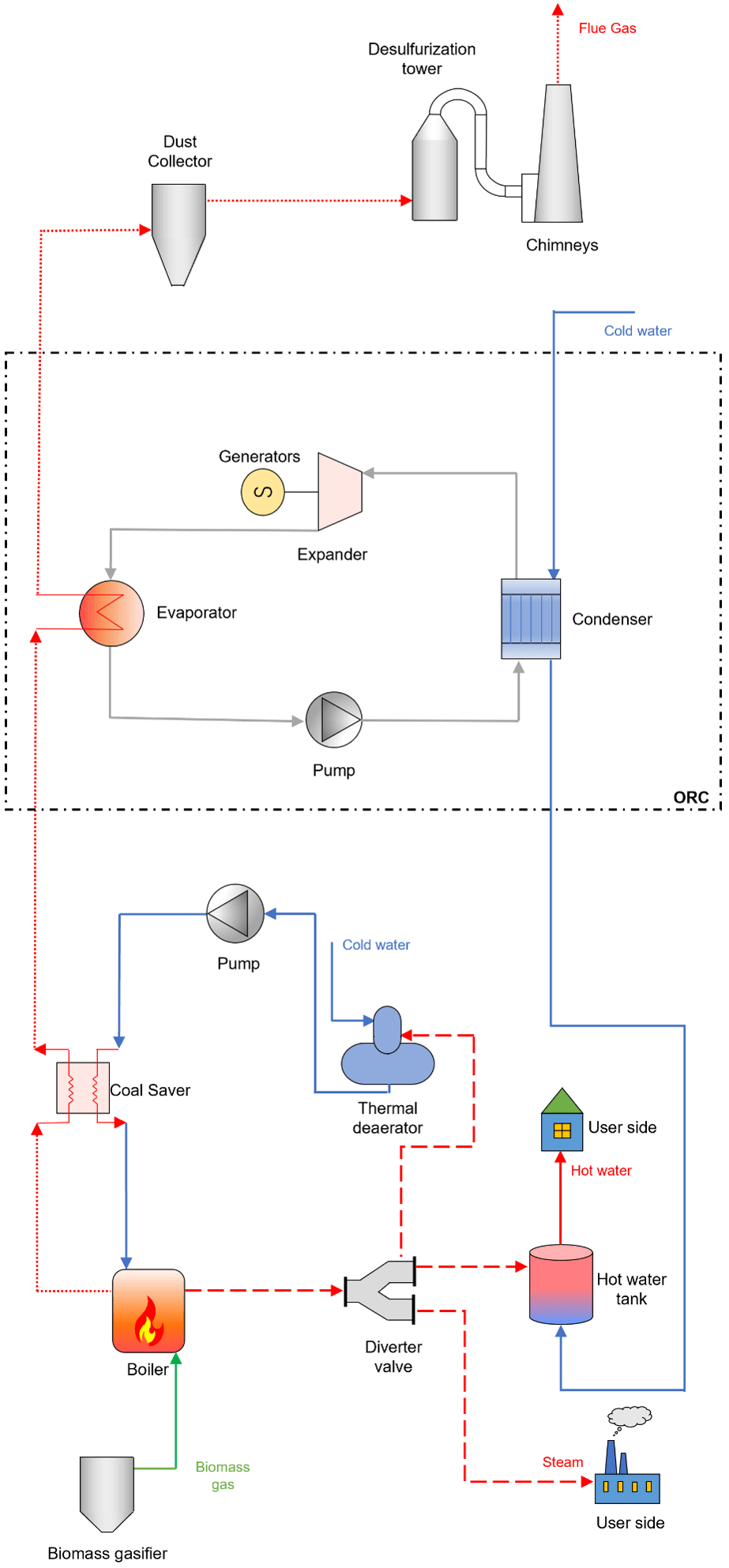
The system in this paper is based on a completed heating station system at a site. The heating station system uses biomass thermochemical conversion technology. The specific process flow is shown in Fig. 1. The biomass (rice husk) is fed into the gasification reactor by the feeding system. Then the pyrolysis and gasification reaction occurs with a small amount of air added at the top, which promotes the pyrolysis of volatile components in the rice husk to produce gas. The biomass gas is fed to the boiler for combustion to provide a heat source for the boiler. A secondary cylinder is provided at the steam outlet of the boiler, one type of steam for industrial steam transport, one type of steam process for heat exchange in the deaerator and one type of steam for supplying heat to the hot water heat exchange station. The feed water is supplied to the boiler after being preheated by the thermal deaerator and coal saver. After the flue gas comes out of the boiler, the fly ash in the flue gas is removed in the duster which enters the desulfurization tower. Finally, it is discharged into the atmosphere through the chimney.
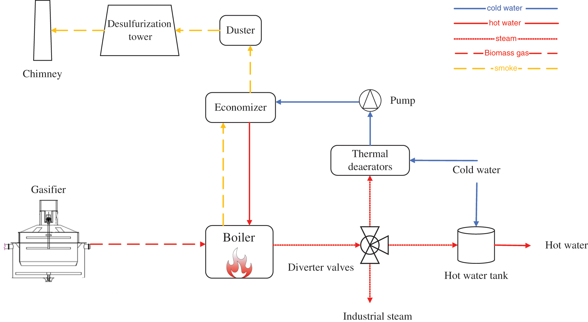
Figure 1: Flowchart of the heating station system
In this paper, by arranging a reasonable flue gas waste heat utilization device, on the one hand, part of the flue gas waste heat is fully utilized, and the fuel consumption of the system can be reduced under the condition of whole unit output to achieve the purpose of energy saving and consumption reduction [12]; on the other hand, the water consumption in the desulfurization process can be reduced with the decline of flue gas temperature at the entrance of the desulfurization tower [13]. It can be seen that the utilization of flue gas waste heat is a crucial way to develop the current boiler energy-saving and emission-reduction technology and improve the overall system efficiency.
The flue gas waste heat recovery ORC system comprises four components: an evaporator, condenser, expander, and working fluid pump [14]. The flow diagram of the ORC system is shown in Fig. 2. Fig. 3 is a T-s diagram of an ORC system that represents the four thermal processes of the system. 1→2s process is the adiabatic expansion process of high-temperature organic steam in the expander, 2s→3 process is the constant pressure cooling and condensing process of the working fluid in the condenser, 3→4s process is the working medium in the active fluid pump adiabatic and pressurizing process, and 4s→1 process is the constant pressure heating evaporation process of the active medium in the steam generator. Since the actual process does not guarantee conditions such as adiabatic constant pressure, there are slashes in the T-s diagram, and 2 and 4 represent the basic state points.
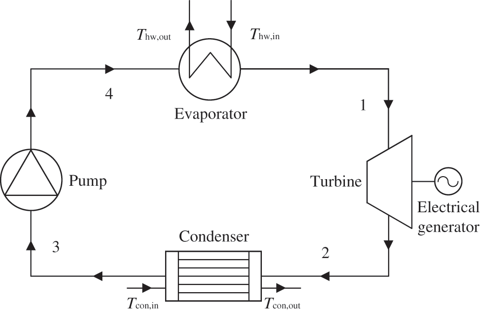
Figure 2: ORC system flowchart
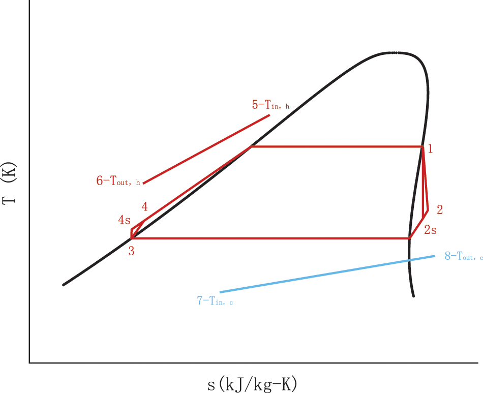
Figure 3: ORC system T-s diagram
The entire thermal process can be described as follows:
(1) Isobaric heat absorption process in the evaporator (4–1).
The heat absorbed by the working fluid in the evaporator is:
In the formula,
(2) The adiabatic expansion process in the expander (1–2).
The working fluid is in a superheated state at the inlet of the expander, that is, the state point 1; the working fluid becomes the state point 2 after adiabatic expansion in the expander. Because there is basic irreversible loss in the expansion process, adiabatic expansion is an entropy increase process. State point 2s is the end point of isotropy expansion under ideal conditions.
The enthalpy value of state point 2 can be calculated by Eq. (2):
In the formula,
The output power of the expander is:
(3) Isobaric exothermic process in the condenser (2–3).
The heat emitted by the working fluid in the condenser is:
In the formula,
(4) Adiabatic compression process in working fluid pump (3–4).
The working medium is in an over-cold state at the inlet of the working medium pump, that is, the status point 3; the active medium becomes the status point 4 after adiabatic compression in the active medium pump. Because there is active irreversible loss in the compression process, adiabatic compression is also an entropy increase process. State point 4s is the end point of isotropy compression under ideal conditions.
The enthalpy value of state point 4 can be calculated by Eq. (5):
In the formula,
The work consumed by the working fluid pump is:
The ORC system’s net output power is:
Thermal efficiency:
2.3.1 Energy Efficiency Analysis
Primary energy utilization is defined as the energy output of the system as a percentage of primary energy consumption, which is one of the most widely used methods in the current combined heat and power system. The higher the value of direct energy utilization, the better the system’s energy saving. Usually expressed in this form, its calculation formula is as follows:
In the formula: P——power generation of heating station, kWh;
Revenue is the net benefit received for all products output by the heating plant. For a pre-improvement heating plant, the output product is mainly steam, and the cost is the cost of fuel and the cost of electricity for the plant. For the improved cogeneration plant, the output product is not only steam but also a certain amount of electricity, which is used to support the whole plant, so the cost of the improved system is only the fuel cost.
In the formula:
The payback period refers to the time required for the total net income of the project to repay the total investment [15]. The formula for calculating the payback period is as follows:
In the formula:
A——Annual profit, yuan.
2.3.3 Environmentality Analysis
The so-called low-carbon economy, whose basic economic model is based on low pollution, low energy consumption and low emissions, is another major progress in the development of human society after agricultural civilization and industrial civilization. To reflect the good environmental friendliness of the biomass gasification CHP system, the CO2 emission reduction (ER) of the system is introduced as the indicator of system environmental assessment. In terms of the whole life cycle, the utilization of biomass energy will not produce CO2, and the contribution to global CO2 is basically “zero” [16]. Therefore, the CO2 generated by the system can only be purchased through the power grid.
The calculation formula of system CO2 emission
In the formula:
This paper is a simulation study of the original system of the heating station using TRNSY software. The components of the equipment are connected graphically and form a modular system form through the simulation interface. After completing the commissioning of each module, the simulation model of the whole system is established, and the output of each equipment module is adjusted according to the actual operation of the heating station [17]. Subsequently, the ORC model was written using Matlab. Finally, the ORC model is called in the Trnsys platform to form a cogeneration system based on ORC waste heat utilization. Fig. 4 shows a graphical representation of the TRNSYS interface cogeneration system.
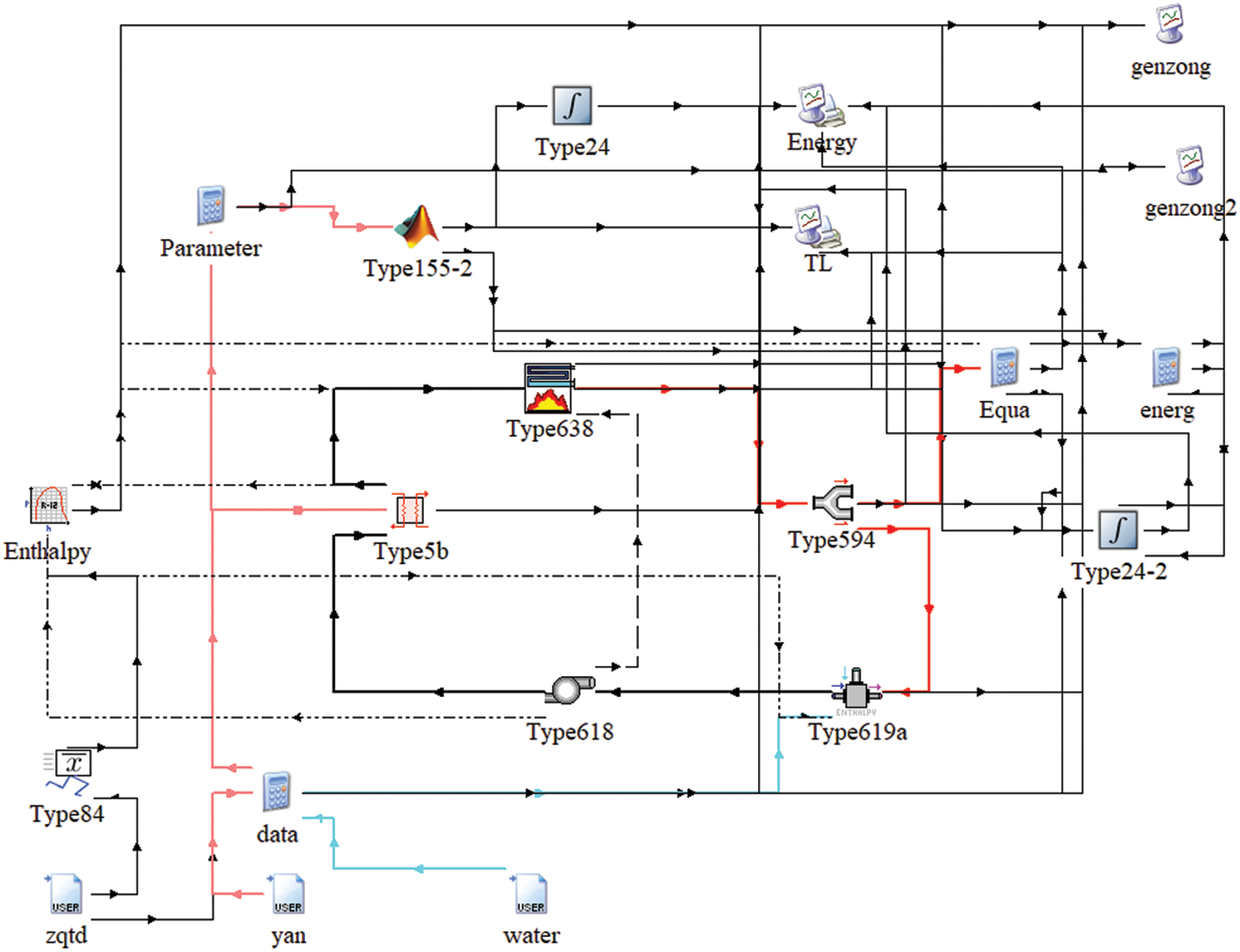
Figure 4: Graphical representation of the energy plant in the TRNSYS
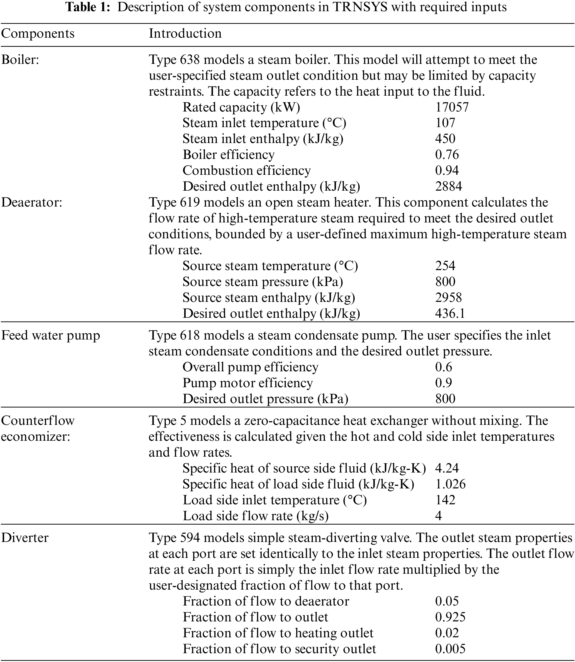
The bottom area shows the deaerator and feeds pump, the economizer on the left side of the cup, and the sub-cylinder on the right after connecting the boiler. At the top is the Rankine loop section that visual Matlab. On the far left is the tool that calls the enthalpy value. Table 1 outlines the Trnsys components, known as “types”, that are selected to model the energy plant as well as the required inputs for each component [18].
The simulation model of the whole system was constructed, and the output of each equipment module was adjusted to verify the accuracy of the whole system simulation by taking the actual operation data of the heating station from July 15 to August 15, 2022, as an example. Fig. 5 shows data comparing the design parameters for steam temperature with the simulation results. Simulated and operational data for the steam flow are shown in Fig. 6. In Fig. 7, the operational information for the actual boiler gas volume and the simulated heat required by the boiler are shown. After removing the bad points, the average relative error in steam temperature is 1.8%, the average relative error in steam flow rate is 9.3%, and the average relative error in heat required by the boiler is 4.9%. In summary, the simulation results have the same trend, and the error is within a reasonable range compared to the actual data, proving the correctness of the model. A comparative analysis of the subsequent system is provided.
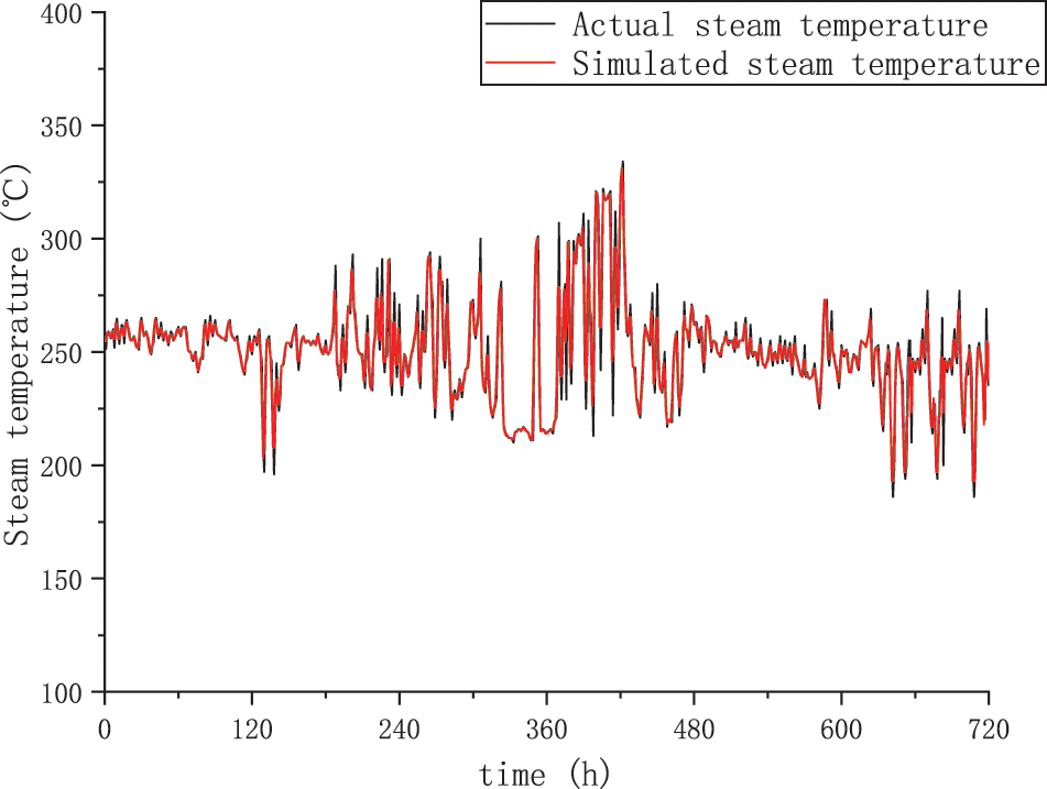
Figure 5: Steam temperature changes over time
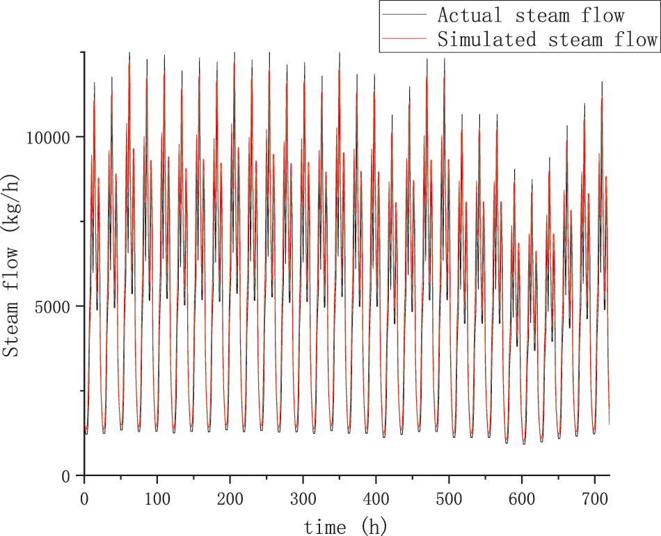
Figure 6: Steam flow changes over time
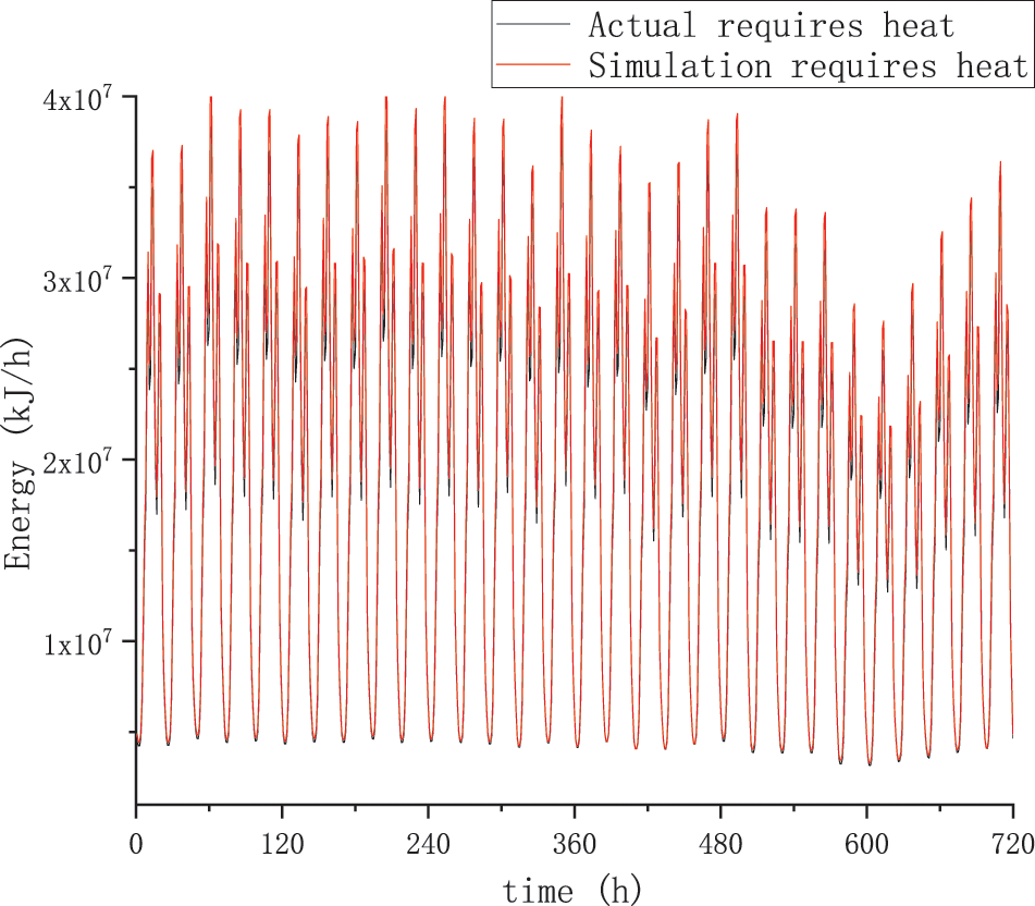
Figure 7: The heat required for the boiler changes over time
4.2 Effect of Operating Parameter on the ORC Performance
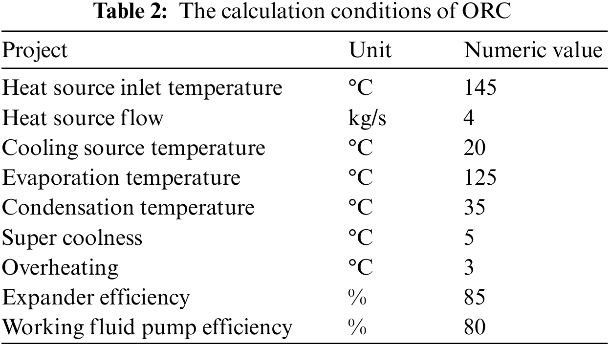
In this study, the effect of various operating parameters on the output power and thermal efficiency of the circulating power generation system was analyzed using boiler flue gas as the low-temperature heat source. To ensure that the actual flue gas temperature can reach the set heat source temperature, the average value of the actual flue gas temperature is taken as the heat source temperature. Therefore, the measured temperature of the heat source is 145°C, and measured the heat source flow rate is 4 kg/s according to the actual situation of the heating station. Take the actual heating station water supply temperature of 20°C as the cold source temperature. The initial conditions for the ORC system calculation are shown in Table 2.
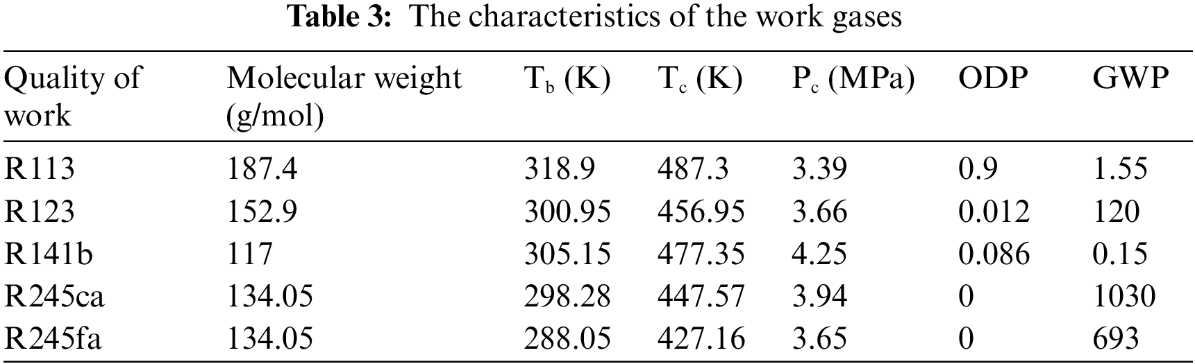
Taking into account the characteristics of the work gases, a part of suitable pure work gases was selected. From Table 3, it is clear that the critical temperatures of the five preferred organic work gases are relatively high, and according to the screening study of organic work gases by Le et al. [19], it is known that organic work gases with higher critical temperatures usually have higher power generation efficiency and better system thermal performance; The analysis shows that the boiling point temperature is lower, which is suitable for the medium and low temperature organic Rankine cycle power generation system, and the ODP and GWP indexes show that the candidate organic work gases have better environmental performance.
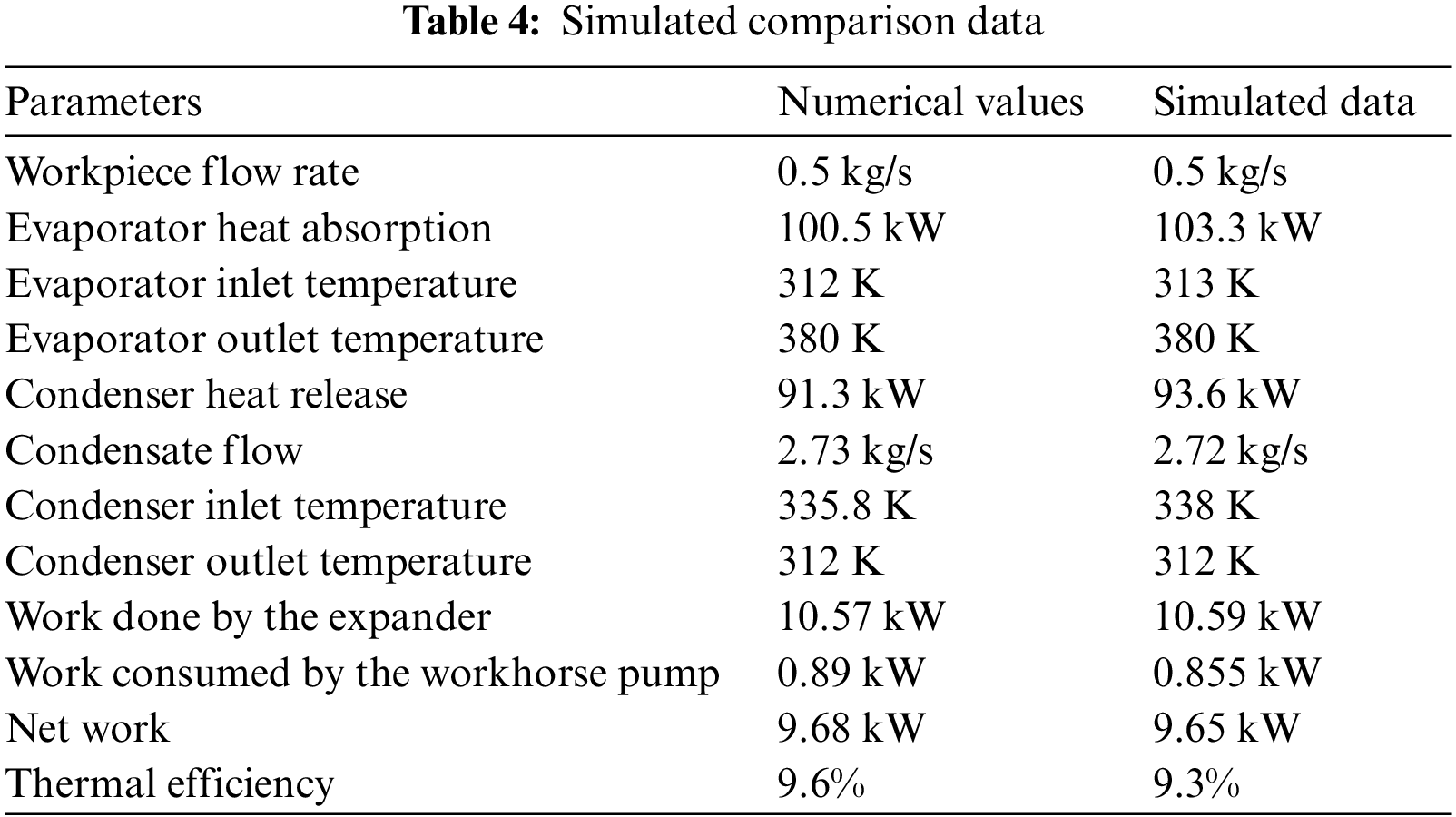
Simulations were carried out using data from other published articles as examples, and the data obtained were compared, and the comparison data are shown in Table 4. The errors are all within reasonable limits, proving that the organic Rankine cycle model is correct and can be used in subsequent analyses.
Modify the input parameters, using the parameters in Table 2 as set input parameters. Using the parameters in Table 2 as set values, the evaporation temperature was varied to simulate the effect of evaporation temperature on the performance of the organ cycle.
As can be seen from Fig. 8, the net output of the system increases gradually with the increase of evaporation temperature. There is not a single peak in the evaporation temperature range selected in this simulation calculation, which maximizes the net output power of the system. When the evaporation temperature increases, the external work of the expander gradually increases, and the exhaust vapor temperature gradually increases. This not only causes a waste of energy but also increases the cost of equipment investment. Therefore, the appropriate evaporation temperature should be selected according to the actual heat source [20].
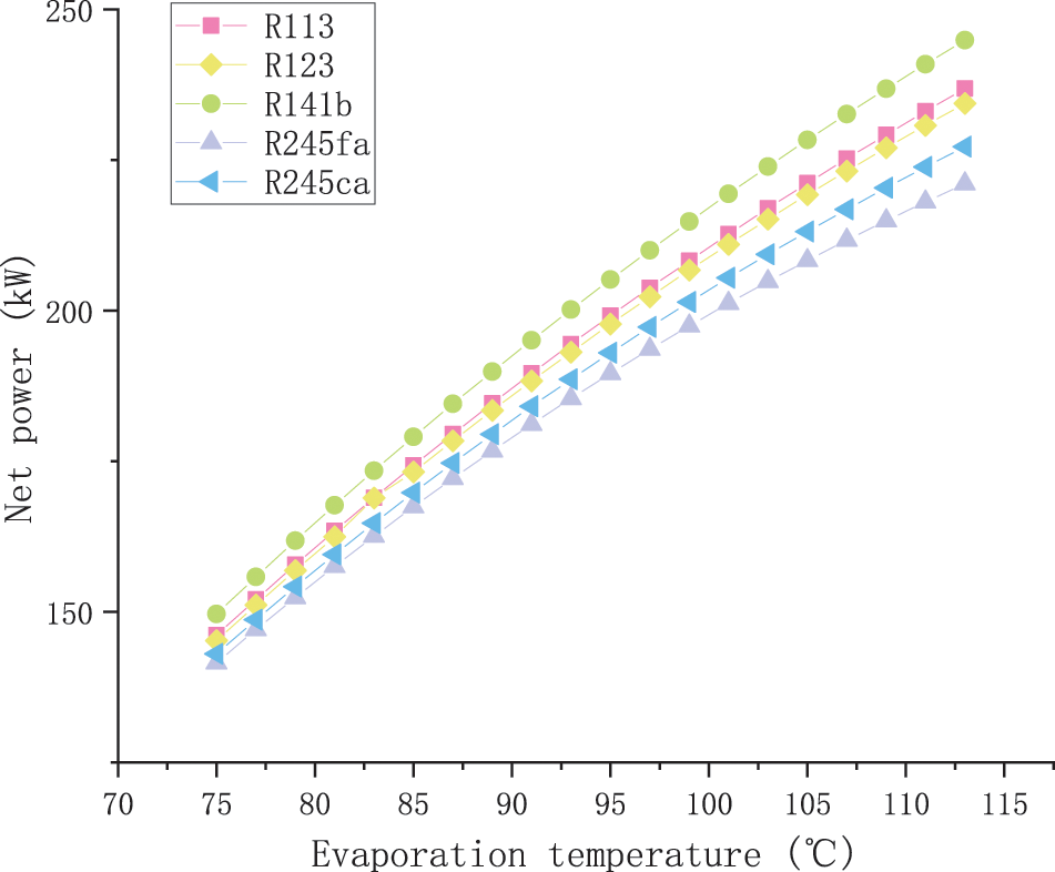
Figure 8: Network that changes with evaporation temperature
As seen from Fig. 9, the thermal efficiency of both working fluid systems increases with the increase of evaporation temperature. However, choosing the optimal evaporation temperature also requires consideration of other factors. The upper limit of the evaporation temperature is limited by the temperature of the heat source. When the evaporation temperature is higher than the critical temperature of the working fluid, the system has a supercritical cycle. The higher the evaporation temperature, the greater the evaporation pressure, resulting in the higher the pressure requirements of the system, and the greater the proportion of the power consumption of the working fluid pump to the expansion work.
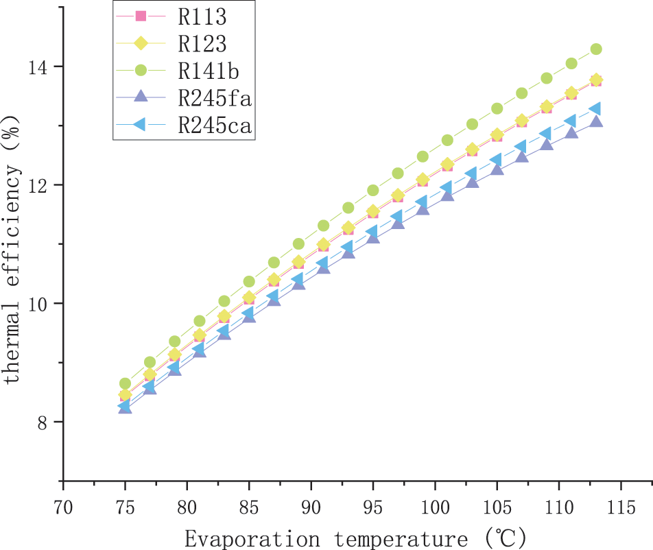
Figure 9: Thermal efficiency as the evaporation temperature changes
Using the parameters in Table 2 as the setpoints, change the condensation temperature to simulate the effect of the condensation temperature on the cyclic performance of the organ.
Fig. 10 shows the effect of the condensing temperature on the net output work. It can be seen that in the case of constant heat source temperature and flow rate, when the evaporation temperature is fixed, the net output work decreases rapidly with the increase of condensation temperature [21]. The reason is that the higher the condensation temperature, the higher the corresponding condensation pressure. At this time, the expansion machine inlet and outlet pressure difference become smaller, the expansion machine output is reduced accordingly. The expansion machine output power reduction is greater than the reduction of pump power consumption, so the net output work decreases with the increase of condensation temperature.
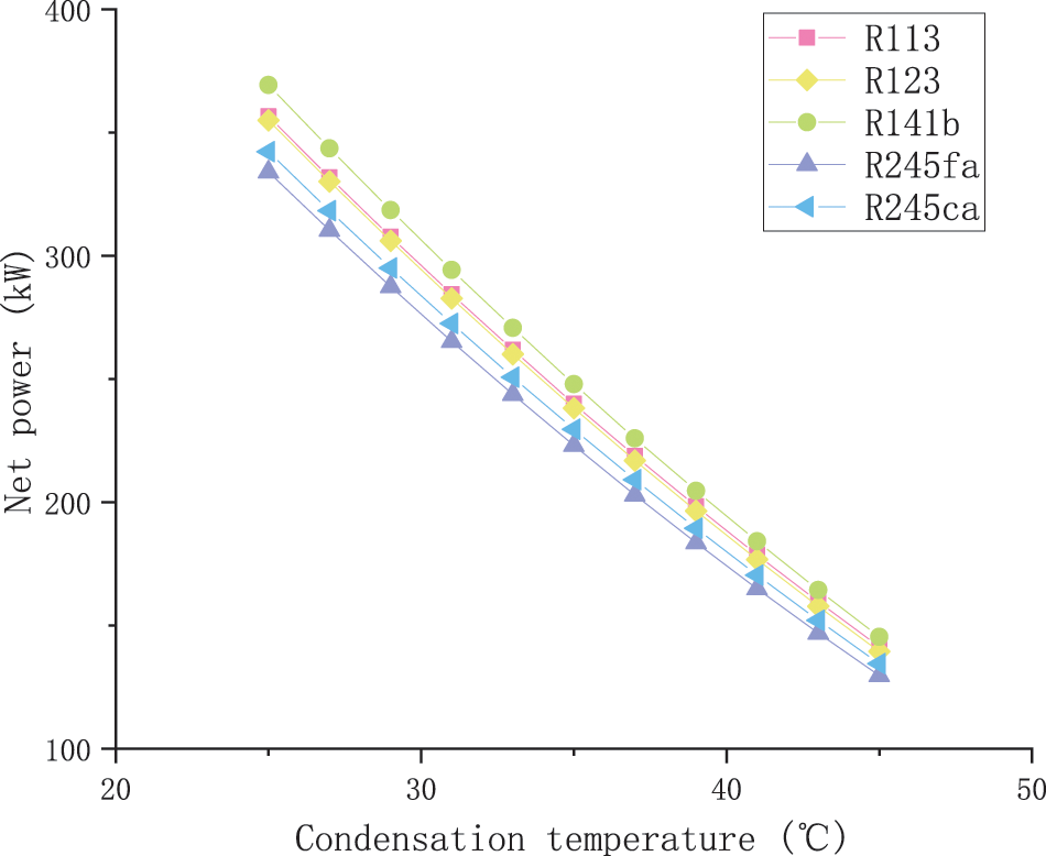
Figure 10: Network that changes with condensation temperature
The changing trend of net work and thermal efficiency of the organic Rankine system with parameters is correct, and the preparation of the organic Rankine cycle model can be used in the combined heat and power supply system of heating stations. It can be seen from the figure that when R141b is used as the working fluid, it has the maximum net output work and thermal efficiency. Therefore, R141b is selected as the circulating working fluid for the following research.
4.2.2 Workspace Selection and Parameter Setting
In summary, take 125°C (398.15 K) for the evaporation temperature and 3 K for the superheat. That is, the evaporator outlet temperature is 128°C (401.15 K), corresponding to the state point 1 in Fig. 3; The cooling water inlet temperature is taken from the ambient temperature of 20°C, the cooling water temperature difference is generally 4°C–8°C [22], the outlet temperature of the cooling water is 26°C (299.15 K), the condensation temperature is 35°C (308.15 K), and the supercooling degree of 5 K is taken to correspond to the state point 3 in Fig. 3. Using MATLAB to call REFPROP to query the properties of the organic working fluid R141b and substitute it for the model calculations in Section 2.2, the parameters of each state point in the looping system can be obtained, as shown in Table 5.
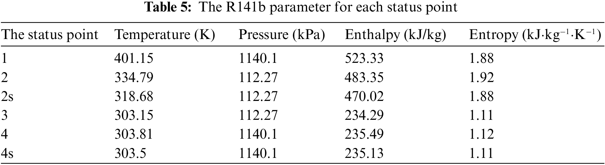
According to Eq. (1) and Table 3, the calculation shows the working fluid flow rate,
4.3 System Energy Efficiency Analysis
4.3.1 Energy Efficiency Analysis
The power generation system is to recover flue gas waste heat, so the investment in heat supply is negligible. The design power consumption of the whole plant is known to be about 300 kWh. Fig. 11 shows the hourly power generation of the Rankine cycle from July 15 to August 15. According to the simulation, the system generated 46000 kWh in this month. Fig. 12 is the actual daily electricity consumption of the whole plant compared with the daily power generation of the system. Although Rankine cycle system can not guarantee the power consumption of the whole plant, it can support 1/4 of the power consumption of the whole plant.
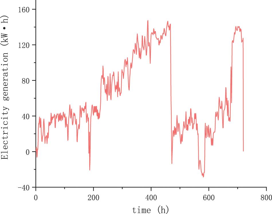
Figure 11: System power generation
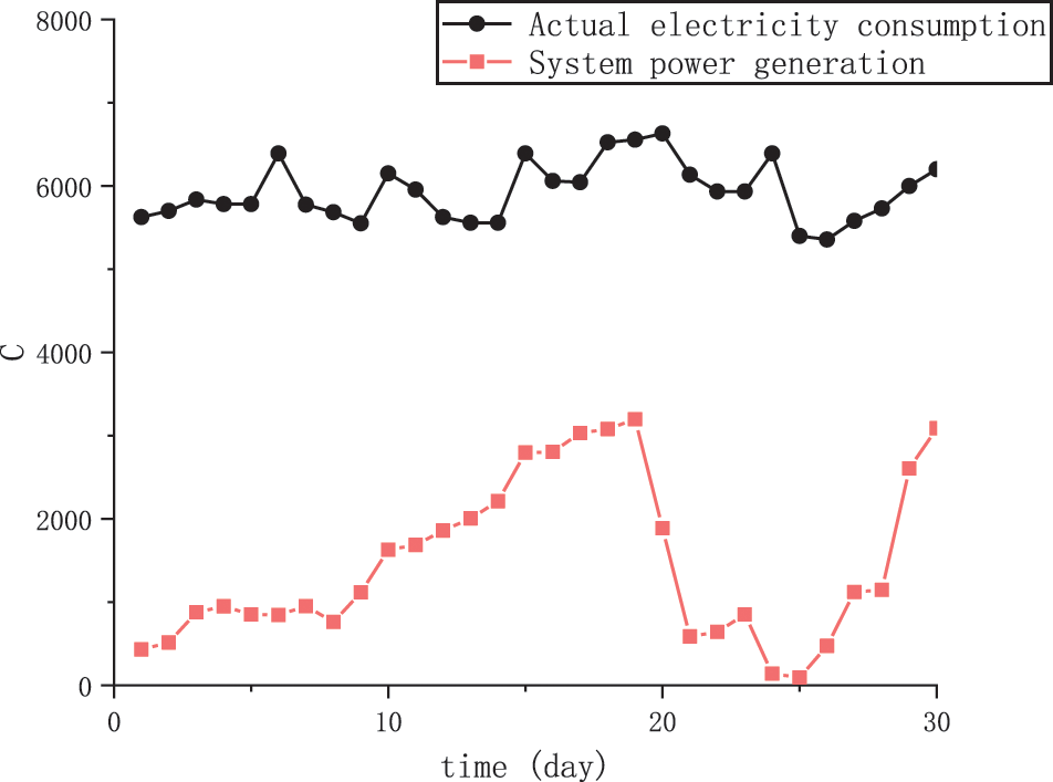
Figure 12: System power generation and plant power consumption
According to statistics, Rankine cycle system generates about 552000 kWh per year. According to the statistics of the actual production capacity provided by the heating station, the heating station generates 112.55 billion kJ of steam heat, 2.49 billion kJ of hot water heat and 158.57 billion kJ of gas heat per year. According to the simulation and formula calculation in Section 2.2, the primary energy utilization rate of the system before transformation is 0.72, and the primary energy utilization rate of the system after transformation is 0.74.
In a Rankine cycle system, the inlet temperature of the cold source water at the condenser end is 20°C and the outlet temperature is 26°C. Therefore, less heat is required to convert the cold source water into hot water. Fig. 13 shows the daily heat savings for one month, which can be calculated to be about 256 million kJ per year. this energy can heat more hot water.
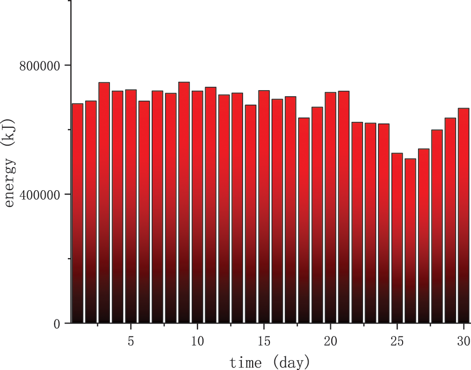
Figure 13: Save calories every day
The calculated flow rate of the extra heated hot water is 870000 kg. The heating station mainly traffics steam, so the amount of steam generated before and after the renovation cannot change, and the fuel consumed remains unchanged.
Commercial and industrial water is 4.10 Yuan/m3, and the converted
The installed power generally refers to the rated power, and the used power generally refers to the output power of 57.67 kW (the usable power is 75%–85% of the rated power). The installed power of ORC unit is set as 76.89 kW. The power generation system is supplied in skid mounted form. According to the installed price of 8000 Yuan/kW, the total price of this unit is about 615100 Yuan, so the investment payback period of the project is about 1.57 years, with significant economic and social benefits.
According to the above chapters, the annual power generation of the system is about 552000 kWh.
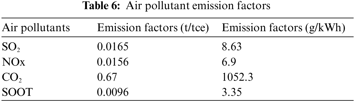
According to the formula in Section 2.2, the CO2 emission of the improved system is reduced by 0.53 tons compared with that before the improvement. Based on the classic recommended data derived from the Energy Research Institute of the National Development and Reform Commission as well as the Chinese Academy of Engineering [23]. The emission factors of air pollutants are shown in Table 6. Assuming that the system generates electricity entirely from thermal power, a reduction in greenhouse effects (CO2, SO2, NOx) can be achieved. Based on a 1 t standard coal power generation capacity of 3000 kWh, we can estimate that the system can save 184 tons of standard coal per year, reduce SO2 emissions by 3 tons, reduce NOx emissions by 2.87 tons, reduce CO2 emissions by 123.28 tons, and reduce soot emissions by 1.76 tons. At the same time, because the expander power generation system uses flue gas waste heat, the discharge of industrial waste heat during power generation is reduced. This also has a significant mitigating effect on thermal pollution caused by power plants and industries.
(1) Combined with the actual operating conditions, based on TRNSYS software, the simulation model of the combined heat and power system was studied and built, the module parameters of the system equipment were adjusted, the simulation results were compared with the actual operating parameters, and the correctness of the model was verified.
(2) This study uses the net output power as an evaluation index to mathematically model the ORC system, which meets the requirements for the evaluation of the advanced energy-saving effect of the waste heat recovery system, and the research content is not only applicable to boiler low-temperature waste heat recovery but also applies to the thermodynamic performance analysis of ORC power generation of other low-temperature heat sources.
(3) R141b is selected as the circulating working medium. According to the calculation, the working fluid flow rate,
(4) The Rankine cycle system generates about 552000 kWh per year. The heating station generates 112.55 billion kJ of steam heat, 2.49 billion kJ of hot water heat and 158.57 billion kJ of gas heat per year. According to the calculation, the primary energy utilization rate of the system before the transformation is 0.72, and that of the system after the transformation is 0.74. The income difference before and after the transformation is 390000 Yuan. The total price of the unit is about 615100 Yuan, and the payback period of the project is about 1.57 years. The economic and social benefits are significant. The improved system reduces CO2 emissions by 0.53 tons compared with the original system.
Acknowledgement: Thanks to the guidance of my tutor, the help of my classmates and the company of my boyfriend.
Funding Statement: The study was supported by research funds from Shanghai’s 2020 Annual Science and Technology Innovation Action Plan: Social development and Science & Technology Project (No. 20dz1205302).
Conflicts of Interest: The authors declare that they have no conflicts of interest to report regarding the present study.
References
1. Shu, G., Li, X., Tian, H., Liang, X., Wei, H. et al. (2014). Alkanes as working fluids for high-temperature exhaust heat recovery of diesel engine using organic Rankine cycle. Applied Energy, 119, 204–217. https://doi.org/10.1016/j.apenergy.2013.12.056 [Google Scholar] [CrossRef]
2. Tian, H., Jiang, N., Jia, Q., Sun, X. X., Shu, G. Q. et al. (2015). Comparison of segmented and traditional thermoelectric generator for waste heat recovery of diesel engine. The 7th International Conference on Applied Energy, Abu Dhabi. [Google Scholar]
3. Nemati, A., Nami, H., Ranjbar, F., Yari, M. (2017). A comparative thermodynamic analysis of ORC and Kalina cycles for waste heat recovery: A case study for CGAM cogeneration system. Case Studies in Thermal Engineering, 9, 1–13. https://doi.org/10.1016/j.csite.2016.11.003 [Google Scholar] [CrossRef]
4. Wang, E. H., Zhang, H. G., Fan, B. Y., Ouyang, M. G., Zhao, Y. et al. (2011). Study of working fluid selection of organic Rankine cycle (ORC) for engine waste heat recovery. Energy, 36(5), 3406–3418. https://doi.org/10.1016/j.energy.2011.03.041 [Google Scholar] [CrossRef]
5. Pierobon, L., Nguyen, T. V., Larsen, U., Haglind, F., Elmegaard, B. (2013). Multi-objective optimization of organic Rankine cycles for waste heat recovery: Application in an offshore platform. Energy, 58, 538–549. https://doi.org/10.1016/j.energy.2013.05.039 [Google Scholar] [CrossRef]
6. Chen, H., Goswami, D. Y., Stefanakos, E. K. (2010). A review of thermodynamic cycles and working fluids for the conversion of low-grade heat. Renewable and Sustainable Energy Reviews, 14(9), 3059–3067. https://doi.org/10.1016/j.rser.2010.07.006 [Google Scholar] [CrossRef]
7. Lecompte, S., Huisseune, H., Broek M.V., B., Vanslambrouck, B., de Paepe, M. (2015). Review of organic Rankine cycle (ORC) architectures for waste heat recovery. Renewable and Sustainable Energy Reviews, 47, 448–461. https://doi.org/10.1016/j.rser.2015.03.089 [Google Scholar] [CrossRef]
8. Champier, D. (2017). Thermoelectric generators: A review of applications. Energy Conversion and Management, 140, 167–181. https://doi.org/10.1016/j.enconman.2017.02.070 [Google Scholar] [CrossRef]
9. Jouhara, H., Khordehgah, N., Almahmoud, S., Delpech, B., Chauhan, A. et al. (2018). Waste heat recovery technologies and applications. Thermal Science and Engineering Progress, 6, 268–289. https://doi.org/10.1016/j.tsep.2018.04.017 [Google Scholar] [CrossRef]
10. Li, Y. Y., Gao, Y. Q., Yang, X. F. (2019). Research status of micro-cogeneration technology based on organic Rankine cyclestatus. Journal of Beijing Institute of Petrochemical Technology, 27(2), 17–25. [Google Scholar]
11. Zhu, Y. (2020). Thermodynamic analysis of biomass direct-fired organic Rankine cycle combined cooling, heating and power system and economic evaluation of carbon capture heat (Ph.D. Thesis). Tianjin University, China. [Google Scholar]
12. Zhang, X. J., Wu, L. J., Wang, X. L., Ju, G. D. (2016). Comparative study of waste heat steam SRC, ORC and S-ORC power generation systems in medium-low temperature. Applied Thermal Engineering, 106, 1427–1439. https://doi.org/10.1016/j.applthermaleng.2016.06.108 [Google Scholar] [CrossRef]
13. Jiang, Y. (2022). Study on the optimization of low temperature coal economizer in thermal power plants. Industrial Heating, 51, 7–10. [Google Scholar]
14. Yang, H., Meng, N., Li, T. L. (2020). Coupling effect of evaporation and condensation processes of organic Rankine cycle for geothermal power generation improvement. Journal of Central South University, 26(12), 3372–3387. [Google Scholar]
15. Wang, Y. P. (2016). Technical and economic study on cogeneration of external combustion engine based on straw gasification (Master Thesis). North China Electric Power University, China. [Google Scholar]
16. Zhou, Z. R., Wu, W. L. (2005). Research status and prospect of biomass energy. Transactions of the Chinese Society of Agricultural Engineering, 21(12), 12–15. [Google Scholar]
17. Marc, C., Behnaz, R. (2018). Investigating steam turbine feasibility to improve the sustainability of a biomass boiler using TRNSYS. Sustainable Cities and Society, 43, 86–94. https://doi.org/10.1016/j.scs.2018.08.032 [Google Scholar] [CrossRef]
18. University of Wisconsin–Madison (1976). TRNSYS, a transient simulation program. USA: The Laboratory. [Google Scholar]
19. Le, V., Kheiri, A. (2014). Thermodynamic and economic optimizations of a waste heat to power plant driven by a subcritical ORC using pure or zeotropic working flui. Energy, 78(1), 622–638. https://doi.org/10.1016/j.energy.2014.10.051 [Google Scholar] [CrossRef]
20. Wang, L., Zhang, R. Q., Jiang, Y. (2018). Analysis of waste heat recovery of power plant thermal system based on organic rankine cycle. 5th International Conference on Systems and Informatics, China. [Google Scholar]
21. Zhang, C. H., Lin, J. Y., Tan, Y. F. (2020). Parametric study and working fluid selection of the parallel type organic Rankine cycle and ejector heat pump combined cycle. Solar Energy, 205, 487–495. https://doi.org/10.1016/j.solener.2020.05.099 [Google Scholar] [CrossRef]
22. Gong, Z. D. (2018). Performance analysis and application simulation of small and micro ORC systems (Master’s Thesis). Tianjin University, China. [Google Scholar]
23. Zhang, H. J. (2014). Optimal design and analysis of organic Rankine cycle for medium and low temperature waste heat power generation (Master Thesis). Tianjin University, China. [Google Scholar]
Cite This Article
 Copyright © 2023 The Author(s). Published by Tech Science Press.
This work is licensed under a Creative Commons Attribution 4.0 International License , which permits unrestricted use, distribution, and reproduction in any medium, provided the original work is properly cited.
 Downloads
 Citation Tools