
 Submit a Paper
 Propose a Special lssue
 Open Access
ARTICLE
Performance Assessment of a Real PV System Connected to a Low-Voltage Grid
1 Electrical Engineering Department, Faculty of Energy Engineering, Aswan University, Aswan, Egypt
2 Faculty of Engineering, King Salman International University, El-Tor, 46511, Egypt
3 Electrical Engineering Department, Faculty of Engineering, Minia University, Minia, Egypt
4 Department of Electromechanics Engineering, Faculty of Engineering, Heliopolis University, Cairo, Egypt
5 Computer Department, Faculty of Engineering, Modern Academy of Engineering & Technology, Cairo, Egypt
* Corresponding Author: Gaber Magdy. Email:
(This article belongs to the Special Issue: Renewable Energy Technologies for Sustainable Energy Production)
Energy Engineering 2024, 121(1), 13-26. https://doi.org/10.32604/ee.2023.043562
Received 06 July 2023; Accepted 25 September 2023; Issue published 27 December 2023
 View Full Text
 Download PDF
Abstract
The generation of photovoltaic (PV) solar energy is increasing continuously because it is renewable, unlimited, and clean energy. In the past, generation systems depended on non-renewable sources such as oil, coal, and gas. Therefore, this paper assesses the performance of a 51 kW PV solar power plant connected to a low-voltage grid to feed an administrative building in the 6th of October City, Egypt. The performance analysis of the considered grid-connected PV system is carried out using power system simulator for Engineering (PSS/E) software. Where the PSS/E program, monitors and uses the power analyzer that displays the parameters and measures some parameters such as current, voltage, total power, power factor, frequency, and current and voltage harmonics, the used inverter from the type of grid inverter for the considered system. The results conclude that when the maximum solar radiation is reached, the maximum current can be obtained from the solar panels, thus obtaining the maximum power and power factor. Decreasing total voltage harmonic distortion, a current harmonic distortion within permissible limits using active harmonic distortion because this type is fast in processing up to 300 microseconds. The connection between solar stations and the national grid makes the system more efficient.Keywords
The importance of renewable energy sources (RESs) is increasing every day because of their clean sources, not polluting emissions where solar and wind energy dominate the new power generation plants, as they have become a reality in the whole world. Due to the impact of weather conditions on renewable power generation, there would be high fluctuations in modern power systems [1]. Solar energy is sustainable and renewable, meaning that it does not run out, as it is a natural source of the sun. It can be used in remote locations that are not connected by electric cables. They are used to meet the electricity needs of satellites. It is the best way to get electric power in the mountains, deserts, and open seas. Grid-connected solar systems are considered a new investment by selling solar energy to electricity distribution companies during the daytime. The use of solar energy as an alternative to fuel is constantly increasing and the most appropriate applications used to benefit from solar energy come through the installation of a system connected to the national grid without the need for energy storage batteries because the system works to pump electricity during the day [2]. The low cost of photovoltaic (PV) production as well as various incentive rules introduced by governments, such as net metering, solar credits, and feed-in tariffs, are the reasons for the rapid growth of the PV sector and the increasing application of solar energy [3]. The stability of the power system results from the network maintaining a constant value of voltage and frequency to ensure the generation, transmission, and distribution of electrical energy to consumers in a way that ensures the work of the devices connected to the network. There are also specific supply voltages, so the electrical network must maintain its value of 220, and 110 V. The power system maintains stability by balancing the power generated with consumption through continuous review and control of the grid. The increase in the energy demand results in a decrease in the grid frequency unless it is matched by an increase in the generated power, which returns the frequency value to its nominal value. Five conditions must be met before the synchronization process between the solar power plants and the electric grid takes place. The solar power generation source must have equal line voltage, frequency, phase sequence, phase angle, and waveform to that of the electric grid to which it is being synchronized [4].
The optimization of the grid-connected PV system method is based on more utilization of the array output power and less electrical power sold to the grid [5]. A comparative study between three different configurations (i.e., power system, stand-alone, PV-interconnected power system with battery energy storage system (BESS)) to be installed in the Zafarana site to feed the load needed to minimize buying energy from the national grid [6]. The best performance of grid-connected PV systems was studied using a list of commercially valid system devices. The analysis depends on selecting a PV module, an optimal number of modules, and the type of module installation, to achieve more benefit during the operational lifetime [7]. The PV systems can be classified according to connected PV systems as follows.
An off-grid system is completely far from the electricity grid and there is no alternative source of energy. The solar system must be relied 100% upon to provide all electricity needs. The plant is designed based on ensure all the needs for electricity throughout all seasons and days of the year. It is recommended to make this system in use where it is possible to dispense with part of the electrical energy during long periods of bad weather. Since there is no support from the network. The best solar system in caravans, camps, and street lighting. The angle of inclination of solar panels is implemented based on achieving the best balance between production and consumption in winter and summer. When designing the system, all the following information must be available: electrical loads (devices and their number), the number of hours of use for each load separately, the Timing of use loads (day or night), geographical location of the project.
On-grid solar systems generate electricity only when connected to the government electricity grid. The inverter in this system is automatically disconnected when the power is cut off. The station is connected to the electricity network and the surplus energy generated from PV cells is sold to the national electricity distribution companies under long-term contracts. It does not unite batteries with a relatively short life span, and this reduces plant costs and operating expenses compared to the standalone or hybrid plant.
Hybrid stations are generally defined as the sharing of two or more different sources of generation (or storage) of electrical energy to provide electrical power to the load. It can be a mixture of both traditional and renewable sources or only renewable. It is characterized by its ability to provide electricity through the panels directly in addition to the current of the national grid or from a backup generator running by diesel or wind energy. The design is based on providing part of the need for electricity by solar energy, not all of the consumption. If the energy generated from the panels is not enough to supply the loads and batteries at peak times, the system will automatically recharge the batteries from the grid or generator. All the energy generated from the cells is used first, then any shortfall in the electricity of the national grid is added, but if there is a power outage, it provides alternative energy through batteries connected to it with different storage capacities that are determined based on the customer’s desire. Hybrid substations have a Hybrid inverter with the following outputs: Solar power source: DC input from panels, Alternative power source: 220-volt AC input or 380 volts (3 phase) coming from the electrical network. Additional alternate source: Some models have a 60 Hz input, coming from the diesel generator, The exit goes to the battery bank and 220 V AC or 380 V (3 phase) output for home use.
Solar power plants are starting in connection to the national electricity grid. Thanks to the Egyptian government’s issuance of Resolution No. 1947 of 2014 on the tariff of renewable energy, individuals in homes and companies are allowed to generate solar energy and sell it to electricity distribution companies at a distinct and fixed price for 25 years. In a grid-connected three-phase PV system, a boost converter with maximum power point tracking (MPPT) is used to get the maximum amount that can be obtained from the sun and transmitted to the grid. The inverter is responsible for converting direct current to alternating current, and it is one of the most important components of the solar plant, which is responsible for controlling the flow of electric current before it is injected into the network. Therefore, a voltage source transformer (VSI) is used [8]. The MPPT is used to control the inverter due to instantaneous changes in solar radiation and temperature [9]. Limited power point tracking (LPPT) is used in certain cases when there is a large surplus in power generation and consumption is low, it is only useful in these cases [10].
The reactive power requirements of the network will decrease as the network can provide less reactive power. This happens when the PV inverter is connected to the grid. Various methods were discussed to operate PV transformers in terms of injection and absorption of reactive power in addition to the functions they perform [11]. The grid-connected PV system is simulated using the real-time digital simulator (RTDS) to study the effect of the variation in the power factor of the loads, the photoelectric penetration, the introduction of harmonics into the system by the photoelectric inverter, and the preventing slip in the PV system on the system’s reliability and connectivity [12]. In the distribution systems, it is required that the PV system connected to the grid be turned on in the event of any disturbances in the system [13]. This type of solar power plant is considered the most economical, as it achieves returns on investment of up to 17%, although it does not provide a solution to the power outage crisis, as the plant does not produce energy during periods of power outages from the national grid. The monitoring system has the functions of displaying real-time monitoring data and querying power generation statistics. So, important data are collected from the working temperature of the solar PV module, the atmospheric temperature, and the amount of sunlight, as well as the generation voltage of the solar PV module [14].
Electricity production losses range from 20% to 25% [15]. From the study of the network-connected system, it was found that when batteries are not used, this reduces the costs of the plant and operating expenses compared to the operating cost of PV power plants, which is approximately 90% less than the high cost of operating conventional electric power plants. In contrast, it was found that in this system, when the power is cut off, the solar station is automatically disconnected. This system generates energy only when the network currently is available. In the event of a power outage, the system becomes suspended and does not provide any backup source of energy. The study showed that the stations are independent of the network and it is not economical when installing an independent system large enough to provide energy for large loads such as air conditioning, central heating, or factories. In the event of cloudy weather for a period exceeding the standards on which the design was based, a decrease in the productivity of the cells occurs. A large loss of electrical energy occurs during the cycle of charging and discharging batteries. This loss is up to 30% just for charging and discharging the batteries, in addition to about 5% waste in the charging regulator and 5% lost in the inverter. Thus, the total loss amounts to about 40% of the energy generated by the panels. In comparison, in the solar system connected to the grid, there are no batteries or charging regulators, so the losses are limited to the inverter and cables to reach only 5%. The causes of losses vary from changes in the current-voltage characteristics of PV units due to manufacturing processes, differences in the orientation and inclination of solar surfaces, and the effects of temperature. The grid-connected PV system encounters various types of distortions during grid failure where when a grid fault appears, the point of common coupling (PCC) will be very low resulting in high DC power-balancing coupling voltage. This downstream voltage may damage the inverter as well; the voltage drop will force the PV system to be disconnected from the grid according to the grid code. The shutdown of a large PV plant may harm the operation of the power system [16].
The PV installation location affects the degradation rate of PV panels as well as the installation locations related to solar radiation and ambient temperature profiles on the lifespan of the transformers [17]. Based on the analysis of the amount of reactive power to enhance voltage stability, a study was developed to display the voltage stability behavior that uses PV systems. A network simulation IEEE-14 with RESs was developed and integrated using the Power System Simulator for Engineering (PSS/E) [18]. The inductor can be used to reduce the flow of current from the inverter to the utility network [19].
The contribution of this paper focused on studying the connection between the solar station and the public network through the PSS/E program alternative to the MATLAB program that works with monitoring and using the power analyzer that displays the parameter. In addition to decreasing the total harmonic distortion of the voltage when connecting the solar station with the network and indicating that the components of the solar station had little losses compared with the network in this system, finally used active harmonic distortion is used to deal with the current harmonics because this type is fast in processing up to 300 microseconds. We can make developing of this paper using a smart meter instead of net metering to measure automatically the amount of energy that has been consumed and the amount of energy produced by the solar panels and calculate the invoice as positive or negative for the customer, this will be done automatically.
This paper presents a new performance-based approach that evaluates a 51-kW solar PV power plant connected to a low-voltage grid to feed an office building in the 6th of October, Egypt. The performance analysis of the grid-connected PV system is performed using the power system simulator for Engineering (PSS/E) software. Where there is a PSS/E program that monitors the system and can be viewed using a power analyzer. This is an alternative to the MATLAB program, and some of the following elements can be measured current, voltage, total power and power factor, frequency, current and voltage harmonics, and the inverter is an on-grid type. The public grid can be fortified with electricity by linking it with the solar station to work together in parallel to make both more efficient. The station is connected to the electricity grid and the surplus energy generated from the PV cells is sold to the national electricity distribution companies under long-term contracts. The system also works to reduce carbon footprints in the biosphere.
3.1 Steps Electrical Network Starting from Station 66 kV to Load with Connection PV Station at Low Voltage
First stage: a step-up transformer is used to raise the voltage from 66 to 500 kV where whenever increase the voltage, decrease the current and power losses as well as the voltage drop, thus reducing the cost. Second stage: use step down transformer to reduce the voltage from 500 to 220 kV and use another one to reduce it from 220 to 66 kV and use the last time use step down transformer to reduce it from 66 to 11 kV or 220 kV but on the 6th of October network, used 11 kV. Third stage: 11 kV is input to the distributor and transformer distribution to reduce from 11 kV to 400 V after that enters to distribute on the box and biller and finally the load. The connection of the PV station to the network 51 kW may happen on the distribution box as shown in Fig. 1. The targeted site has been prepared on the rooftop of the administrative building of the 6th of October City, Egypt to connect a 51-kW solar PV station with a low-voltage grid (distribution box). Then we brought the components of solar energy from solar panels, installation structures, charging regulators, connectors, cables, the on-grid inverter, grounding system, and protection until the installation of the solar energy system is completed. The PSS/E program monitors and analyses the nature of the considered grid-connected PV system. The panels absorb sunlight and produce DC electricity, and through the inverter, which converts it into 220 AC volts, more energy than is needed is pumped into the grid through a net meter.
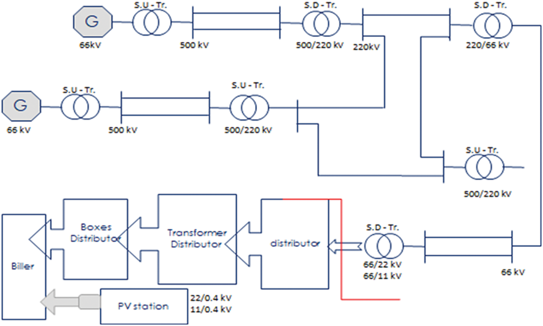
Figure 1: Electrical network starting from station 66 kV to load with connection PV station at low voltage
3.2 Steps to the Connected Solar Panel of the Administrative Building of 6th of October to the National Grid
1. Providing the necessary stands on which the panels can rest.
2. Prepare the solar panel and mounting structure of your panel.
3. Connect electric wires by using an MC4 connector and there are three types of connection (series, parallel, and series-parallel).
4. Connection of solar panel to the solar inverter.
5. Connected solar inverter to the battery.
6. Connected solar inverter to the grid.
Preparing the site (on the rooftop of the administrative building of the 6th of October City to connect the solar station, and we brought the components for solar energy from solar panels, installation structures, charging system, connectors, cables, on-grid inverter, grounding and protection system until the solar energy installation system is completed, and after the completion of its installation, it is the connection between the solar station and the network through the PSS/E program, and this can be viewed through the Power analyzer. The panels absorb sunlight and produce DC electricity, which passes through the inverter, which converts it into 220-volt AC energy, where a meter called net metering is installed. It is a bidirectional meter. This counter reads backward when the generation of the electric panels is greater than the consumption, and this value is added to the customer’s balance. In the end, a comparison is made between the amount of energy that was consumed and the amount of energy produced by the solar panels, and the customer’s bill is either positive or negative.
A dual bidirectional meter is installed, this meter reads in reverse when the generation of electrical panels is greater than consumption and this value is added to the customer’s balance, and at the end, a comparison is made between the amount of energy that has been consumed and the amount of energy produced by the solar panels and the customer’s invoice either positively or negatively. The studies conducted to connect the solar PV station to the grid are shown in Table 1.

4.1 Measuring Voltage of a Solar PV Station Connected to the Network
In accordance with the Egyptian Distribution Code 4-1-1, a PV that operates in parallel with the utility system shall operate within the limits of the voltage variation in the range of ±10% of the nominal voltage. The maximum permissible voltage according to the code for connecting solar power stations = 220 + 10% = 242 volts, the minimum permissible voltage according to the code for connecting solar power stations = 220 − 10% = 198 volts. Using the program PSS/E has facilitated the measurement of some parameters and made monitoring the nature of the considered system. From Fig. 2, it is clear that the value of the voltage ranged between 220 to 250 V throughout the whole day, as the voltage was measured about every forty minutes. The results exceeded the permissible values during the measurements period during the actual operating periods of the station because the distribution network voltage is high, based on the measurements of the connection point after disconnecting the station. We recommend informing the competent networks that there is a voltage surge.
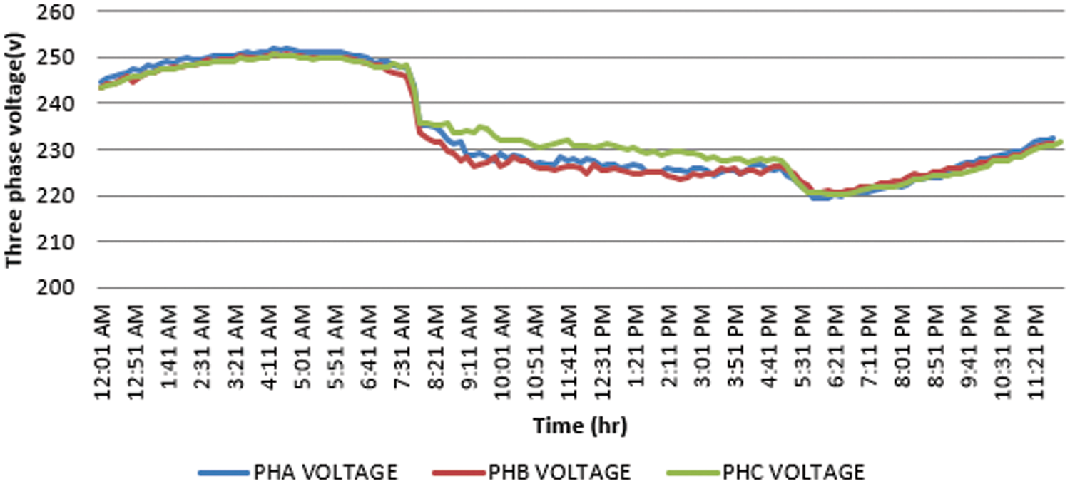
Figure 2: Three-phase voltage of the studied PV solar station connected to the grid
4.2 Measuring Current of a Solar PV Station Connected to the Network
We note that the value of the electric current changes depending on the amount of solar radiation. Fig. 3 shows that the value of the current is maximum at the peak time at 12.30 pm and the value of the current reached 50 A and that when there is no radiation at time 12 am up to time 6 am, after 6 am the amount of radiation increases so the current start to increase up to reach at 12.30 pm, after that the radiation is decreased again and current decreases until reach at time 5 pm the current reach to zero.

Figure 3: Three-phase current of the considered solar PV station connected to the grid
These figures showed that in the period from 12 am to 7 am, the value of the current may be zero, and this is due to the absence of solar radiation in that period and therefore the absence of power and power factor in this period. It is clear that from 7 am the value of the current increases exponentially until the time reaches 12.30 pm, and therefore the value of both the power and power factor increases incrementally due to the presence of the maximum value of solar radiation. It was noticed that after 12.30 pm the current begins to decrease continuously until it reaches 5 pm the value of the current will be zero, and this is due to the lack of solar radiation. This excremental is done in November month.
4.3 Measuring Total Power Using the Power Analyzer of a Solar PV Station Connected to the Grid
The maximum value of power occurs when the solar radiation is as much as possible because the value of the power depends on the value of the current produced by the solar panels. Fig. 4 shows the maximum value of the total power at 12.30 pm is 30.6 kW. The single-phase and three-phase power can be calculated as shown in Eqs. (1) and (2).
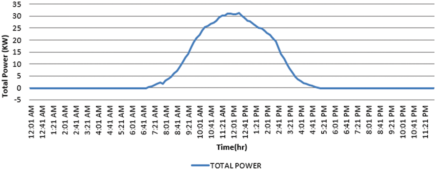
Figure 4: Total power of the considered solar PV station connected to the grid
where
The total power experimentally must be the same when measuring total power theoretically.
4.4 Measuring Power Factor of a Solar PV Station Connected to the Network
We noticed that from the results shown in Fig. 5, from 12 am to 6.30 am, there is no solar radiation value, so the power factor becomes lead because the effective power is almost equal to zero and the ineffective power is present in the inverter capacitor, this makes the power factor negative, that is, the current is leading the voltage. From 7.30 am, the solar radiation begins to increase gradually, so the power value reaches 85%. In this case, the power factor will lag until it reaches 4 pm. The solar radiation begins to decrease until the radiation is absent, so the power factor becomes negative again. and this is written in the datasheet of the inverter. The results were in accordance with the requirements of the code for connecting solar power stations during the measurement period during the actual operating periods of the station.
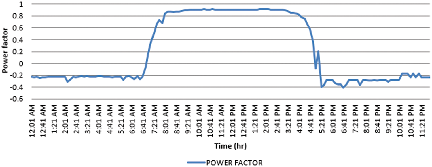
Figure 5: Measuring power factor of the solar PV station connected to the network
4.5 Measuring the Frequency of the Studied Solar PV Station Connected to the Network
One of the conditions for connecting the solar PV station to the network is that the output frequency of the solar PV station is the same as the output frequency of the network. The frequency in Egypt is 50 HZ. In accordance with the Distribution Code 4-1-3, a PV that operates in parallel with the utility system shall operate within the frequency trip limits (48.5–51 Hz) [20]. The system must be stopped to utility line activation within 500 ms for the permissible range and delay to avoid unnecessary tripping in functionality system must allow continuity operation for short-term disturbances. The results shown in Fig. 6 did not exceed the permissible values during the measurement period during the actual operating periods of the station Where the maximum frequency in the figure was 50.2 Hz and the lowest frequency in the figure was 49.7 Hz.

Figure 6: Frequency of the solar PV station connected to the network
4.6 Sources of Harmonics for the Grid-Connected Solar PV System
In case uncorrected loaded or no load, non-linear loads such as computers-fluorescent lamps-electric arc equipment-welding machines-electric furnaces, Inverter during conversion from dc to ac, coils inside motor electric machines, and AC regulators.
4.7 Measuring Total Harmonic Distortion of the Solar PV Station Connected to the Network
The current THD (
where
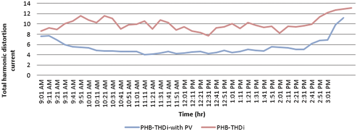
Figure 7: THD current before and after the connected PV solar station to the network
Total harmonic current distortion shall be less than 5% at the rated generator output in accordance with IEC 61727:2004. Because the tolerance is up to 5% and from the shown network the harmonic distortion current for the grid and after connected to the network is greater than 5% so to solve this problem, it is necessary to use the active harmonic filter. The working principle of the active harmonic filter is to monitor the harmonics in the network and generate harmonic waves equal in value and frequency and opposite in direction so that the result becomes zero. This process can take place at a very fast speed that can reach 300 microseconds. These filters cancel the harmful harmonics in the network in various load conditions and do not exceed the rated capacity of the filter. Table 2 shows the current distortion limit as a function of harmonics.

The voltage THD (
where

Figure 8: THD voltage before and after the connected PV solar station to the network
This paper discussed the performance of a 51 kW PV solar power plant connected to a low-voltage grid to feed an administrative building on the 6th of October City, Egypt. This plant covers the administrative building’s electricity needs and feeds the surplus into the low-voltage network. This study was conducted using PSS/E which works with monitoring and using the power analyzer that displays system parameters. The results show that when maximum solar radiation is attained, the maximum current may be generated from the solar panels, resulting in maximum power and power factor. Using active harmonic distortion to reduce total voltage harmonic distortion and current harmonic distortion within allowable limits since it is rapid in processing up to 300 microseconds. The link between solar stations and the national grid improves the system’s efficiency.
Acknowledgement: The authors acknowledge the reviewers for providing valuable comments and helpful suggestions to improve the manuscript.
Funding Statement: The authors received no specific funding for this study.
Author Contributions: The authors confirm their contribution to the paper as follows: study conception and design: Gaber Magdy, Mostafa Metwally, and Adel A. Elbaset; data collection: Mostafa Metwally; analysis and interpretation of results: Gaber Magdy, Adel A. Elbaset, and Esam Zaki; draft manuscript preparation: Gaber Magdy and Mostafa Metwally. All authors reviewed the results and approved the final version of the manuscript.
Availability of Data and Materials: Data sharing is not applicable to this article as no datasets were generated or analyzed during the current study.
Conflicts of Interest: The authors declare that they have no conflicts of interest to report regarding the present study.
References
1. Mosleh, B., Rahme, C. P., Beaino, P., Mattar, R., Nassif, E. A. (2014). Contribution to clean energy production using a novel wave energy converter: Renewable energy. International Conference on Renewable Energies for Developing Countries, pp. 108– 111. Beirut, Lebanon. [Google Scholar]
2. Forbes, Perry Jr, L. (2017). The alternative to fossil fuels: Using solar energy to power the Twin Cities Metro, Minnesota, USA, vol. 20, pp. 1–11. Saint Mary’s University of Minnesota University Central Services Press. [Google Scholar]
3. Haffaf, A., Lakdja, F., Ould Abdeslam, D., Meziane, R. (2021). Monitoring, measured and simulated performance analysis of a 2.4 kWp grid-connected PV system installed on the Mulhouse campus, France. Energy for Sustainable Development, 62, 44–55. [Google Scholar]
4. Spertino, F., Graditi, G. (2014). Power conditioning units in grid-connected photovoltaic systems: A comparison with different technologies and wide range of power ratings. Solar Energy, 108(1), 219–229. [Google Scholar]
5. Rekioua, D., Rekioua, T., Soufi, Y. (2015). Control of a grid connected photovoltaic system. 2015 International Conference on Renewable Energy Research and Applications (ICRERA), pp. 1675–1687. Palermo, Italy. [Google Scholar]
6. Roman, E., Alonso, R., Ibanez, P., Elorduizapatarietxe, S., Goitia, D. (2006). Intelligent PV module for grid-connected PV systems. IEEE Transactions on Industrial Electronics, 53(4), 1066–1073. [Google Scholar]
7. Kornelakis, A., Koutroulis, E. (2009). Methodology for the design optimisation and the economic analysis of grid-connected photovoltaic systems. IET Renewable Power Generation, 3(4), 476–492. [Google Scholar]
8. Dhaneria, A. (2020). Grid connected PV system with reactive power compensation for the grid. IEEE Power & Energy Society Innovative Smart Grid Technologies Conference (ISGT), pp. 1–5. Washington, USA. [Google Scholar]
9. Mohammed, A. Y., Mohammed, F. I., Ibrahim, M. Y. (2017). Grid-connected photovoltaic system. International Conference on Communication, Control, Computing and Electronics Engineering (ICCCCEE), pp. 1–5. Khartoum, Sudan. [Google Scholar]
10. AbdEl-Gawad, H., Sood, V. K. (2017). Kalman filter-based maximum power point tracking for PV energy resources supplying DC microgrid. IEEE Electrical Power and Energy Conference (EPEC), pp. 1–10. Saskatoon, Canada. [Google Scholar]
11. Salama, H. S., Magdy, G., Bakeer, A., Vokony, I. (2022). Adaptive coordination control strategy of renewable energy sources, hydrogen production unit, and fuel cell for frequency regulation of a hybrid distributed power system. Protection and Control of Modern Power Systems, 7(1), 1–18. [Google Scholar]
12. Kanchev, H., Hinov, N., Amaudov, D., Stanev, R. (2017). Modelling and control of a grid-connected PV system for smart grid integration. 40th International Spring Seminar on Electronics Technology (ISSE), pp. 1–6. Sofia, Bulgaria. [Google Scholar]
13. Magdy, G., Shabib, G., Elbaset, A. A., Mitani, Y. (2018). Frequency stabilization of renewable power systems based on MPC with application to the Egyptian grid. IFAC-PapersOnLine, 51(28), 280–285. [Google Scholar]
14. Sreedevi, J., Ashwin, N., Raju, M. N. (2016). A study on grid connected PV system. 2016 National Power Systems Conference (NPSC), pp. 1–6. Bhubaneswar, India. [Google Scholar]
15. Abbasi, M. H., Al-Ohaly, A., Khan, Y., Hasainen, H. M. (2014). Design phases for grid-connected PV system. International Conference on Renewable Energy Research and Application (ICRERA), pp. 684–688. Milwaukee, USA. [Google Scholar]
16. Magdy, G., Shabib, G., Abdel Elbaset, A., Kerdphol, T., Qudaih, Y. et al. (2018). A novel design of decentralized LFC to enhance frequency stability of Egypt power system including wind farms. International Journal on Energy Conversion, 15(1), 17–29. [Google Scholar]
17. Kumar, A., Mandal, R. K., Raushan, R., Gauri, P. (2020). Grid connected photovoltaic systems with multilevel inverter. International Conference on Emerging Frontiers in Electrical and Electronic Technologies (ICEFEET), pp. 1–9. Patna, India. [Google Scholar]
18. Tseng, K. H., Chou, C. J., Liu, T. C., Liu, K. C. (2016). Planning and setup of grid-connected photovoltaic generation systems. 2016 IEEE 11th Conference on Industrial Electronics and Applications (ICIEA), pp. 837–842. Hefei, China. [Google Scholar]
19. Cao, J., Zhang, W., Xiao, Z., Hua, H. (2019). Reactive power optimization for transient voltage stability in energy internet via deep reinforcement learning approach. Energies, 12(8), 1–17. [Google Scholar]
20. Wang, Y., Ren, B., Zhong, Q. C. (2016). Robust power flow control of grid-connected inverters. IEEE Transactions on Industrial Electronics, 63(11), 6887–6897. [Google Scholar]
21. Egyptian Electric Utility and Consumer Protection Regulatory Agency (Egypt ERA) (2014). Technical requirements for connecting small scale PV (SsPV) systems to low voltage distribution networks. http://egyptera.org/ar/Download/Code/SsPVCODE.pdf (accessed on 22/11/2023) [Google Scholar]
22. Nojeng, S., Hassan, M. Y., Said, D. M., Abdullah, M. P., Hussin, F. (2015). Harmonic distortion contribution for the transmission loss allocation in deregulated energy market: A new scheme for industry consumer. Journal of Electrical Engineering and Technology, 10(1), 1–7. [Google Scholar]
Cite This Article
 Copyright © 2024 The Author(s). Published by Tech Science Press.
This work is licensed under a Creative Commons Attribution 4.0 International License , which permits unrestricted use, distribution, and reproduction in any medium, provided the original work is properly cited.
 Downloads
 Citation Tools