
 Submit a Paper
 Propose a Special lssue
 Open Access
ARTICLE

Automatic SOC Equalization Strategy of Energy Storage Units with DC Microgrid Bus Voltage Support
1 School of Automation & Electrical Engineering, Lanzhou Jiaotong University, Lanzhou, 730070, China
2 Key Laboratory of Opto-Technology and Intelligent Control (Lanzhou Jiaotong University), Ministry of Education, Lanzhou, 730070, China
* Corresponding Author: Shenglin Mo. Email:
Energy Engineering 2024, 121(2), 439-459. https://doi.org/10.32604/ee.2023.029956
Received 15 March 2023; Accepted 23 August 2023; Issue published 25 January 2024
 View Full Text
 Download PDF
Abstract
In this paper, an improved sag control strategy based on automatic SOC equalization is proposed to solve the problems of slow SOC equalization and excessive bus voltage fluctuation amplitude and offset caused by load and PV power variations in a stand-alone DC microgrid. The strategy includes primary and secondary control. Among them, the primary control suppresses the DC microgrid voltage fluctuation through the Ⅰ and Ⅱ section control, and the secondary control aims to correct the P-U curve of the energy storage system and the PV system, thus reducing the steady-state bus voltage excursion. The simulation results demonstrate that the proposed control strategy effectively achieves SOC balancing and enhances the immunity of bus voltage. The proposed strategy improves the voltage fluctuation suppression ability by approximately 39.4% and 43.1% under the PV power and load power fluctuation conditions, respectively. Furthermore, the steady-state deviation of the bus voltage, ΔUdc is only 0.01–0.1 V, ensuring stable operation of the DC microgrid in fluctuating power environments.Keywords
Nomenclature
| PV | Photovoltaic system |
| ESS | Energy storage system |
| ESU | Energy storage unit |
| Rd | Sag coefficient |
| ΔP | Unbalanced power |
| SOC | State of charge |
| MPPT | Maximum power point tracking |
| Udc | DC bus voltage |
| ΔUdc | Bus voltage deviation |
| U* | DC bus voltage setting value |
| Uref | Value of DC bus voltage obtained from secondary control |
| Ib | Output current of energy storage unit |
| Mbes | Voltage compensation value for secondary control |
| Asoc | Average state of charge |
| Pbesn | Rated power of energy storage |
With the development of industrialization and urbanization, the demand for energy by humans has increased exponentially. It has become evident that fossil fuels are no longer sufficient to meet this growing demand, and their use has caused increasingly severe environmental problems. Therefore, developing and using renewable energy has become an inevitable trend [1,2]. In the field of new energy, photovoltaic (PV) power generation has become a major part of the global increase in power generation capacity, and one of the most important green technologies. However, the volatility and unpredictability of new energy bring certain challenges to the stability of the existing electrical grid [3]. To improve the acceptance capacity of the existing electrical grid for distributed energy, scholars have proposed the concept of a direct current (DC) microgrid [4]. This microgrid is characterized by independence from reactive power, harmonic and phase frequency synchronization, with only the need to maintain stable DC bus voltage. A basic DC microgrid is composed of distributed power sources, energy storage units, loads, and other components according to a topological structure [5]. Because of its simple and straightforward structure, location independence, high energy efficiency, and low environmental impact, DC microgrids can adapt well to the randomness of distributed energy output, among other benefits. This discovery has received widespread attention from scholars [6].
On the other hand, the electricity grid energy storage system also faces pressure to absorb and balance the power, which requires the maximum utilization of the energy storage system (ESS) to achieve power balance in the electricity grid in the shortest time possible and suppress direct current (DC) bus voltage fluctuations [7–9]. However, excessive use of ESS may cause some ESS units to frequently enter the deep charge and discharge zone, which affects their service life and leads to issues with voltage stability analysis on the grid side [10]. To improve the DC bus voltage disturbance resistance and extend the ESU service life, some researchers have proposed adding droop control to the DC microgrid [11–14]. This method uses droop control characteristics to distribute power to each ESU, and calculates the droop coefficient Rd required in the droop control link by measuring and recording the real-time unbalanced power ΔP and the existing SOC variables of each ESU. Then, it switches control modes and implements control strategies accordingly [15]. Furthermore, it adjusts the output of ESUs with different SOC in real-time by changing the line virtual impedance variable to quickly suppress bus voltage fluctuations and achieve SOC balancing for ESU [16].
Currently, some scholars have researched SOC balancing problems for ESU in DC microgrids and proposed a control strategy based on dynamic load allocation, which determines the droop coefficient based on the SOC value of the energy storage unit to achieve power allocation proportional to SOC [17–20]. However, the disadvantage of this control strategy is that the droop coefficient Rd is linearly related to SOC, and the SOC of energy storage units in DC microgrids often changes slowly, which indirectly causes slow changes in the droop coefficient Rd and cannot achieve rapid SOC balance. To solve this problem, people have proposed an adaptive droop coefficient control strategy, which determines the droop coefficient based on the power function form of SOC changes and improves the power distribution effect to a certain extent. It is more suitable for suppressing bus voltage fluctuations and achieving SOC balance in the droop control link [21,22]. However, this control method has complex control structures and ignores the steady-state bus voltage deviation caused by traditional droop control defects. Therefore, this paper conducts a deep investigation into the voltage fluctuations and deviation caused by the load and photovoltaic power changes in the DC microgrid, as well as the SOC balance of multiple ESUs.
The format of this article is as follows: Section 2 briefly introduces the structure and layered control method and principles of DC microgrids. Section 3 describes the improved droop control strategy based on SOC. The strategy discusses the primary control under different operating conditions in segments and incorporates the principles of secondary control to address the impact of virtual impedance value on DC microgrid systems caused by excessively high virtual impedance values in traditional droop control links. Section 4 discusses the suppression of voltage fluctuations and deviations in bus loads and photovoltaic different operating conditions in DC microgrid systems and compares the SOC balance of different control strategies for ESU. The article concludes with a summary of the findings.
2 DC Microgrid Structure and Hierarchical Control
The optical storage DC microgrid structure, as shown in Fig. 1, is analyzed in this paper. The system consists primarily of PV, ESS comprising batteries, AC and DC loads, and other components. The PV is connected to the DC microgrid through the unidirectional DC-DC converter PV-DC. The ESS is connected to the DC microgrid through the bidirectional DC-DC converter B-DC. Finally, the AC and DC loads are connected to the DC microgrid via the voltage converter L-VSC and the DC-DC converter L-DC.

Figure 1: Structure of DC microgrid
2.2 Hierarchical Control of DC Microgrid
The overall working logic diagram is shown in Fig. 2, Ppv is the output power of the photovoltaic terminal, and Pload is the load power.

Figure 2: Working logic diagram of independent DC microgrid
Firstly, the absolute value of unbalanced power |ΔP| of the whole system will be measured, and when |ΔP|< the maximum power of the energy storage system PBes_max, the system will enter the energy storage and voltage stabilization mode (primary Ⅰ section control). Specifically, the system will judge whether it needs to enter the storage voltage stabilization mode based on the absolute value of the measured unbalanced power, and then use the ESU to dissipate the unbalanced power to achieve voltage stabilization, to balance the power and stabilize the voltage of the system.
It should be noted that the long time energy storage and voltage stabilization may cause the SOC of the ESU to enter the deep charging and discharging state, thus affecting the life and performance of the energy storage unit. To avoid this situation, this paper adds charging state threshold Xsocn1 and discharging state threshold Xsocn2 to the control strategy. When the SOC of the energy storage unit enters the range of these thresholds, the system will exit the energy storage voltage stabilization into the PV voltage stabilization mode, thus protecting the life and performance of the ESU.
When the system enters the PV regulator mode (primary II control), the PV side switches from MPPT mode to sag control mode and adjusts the output power value of the PV side by calculating the ΔP size in real time and changing the virtual impedance size in the sag control link, to achieve system power balance and voltage stability.
If |ΔP| is greater than the maximum power of the entire ESS PBes_max, to ensure the stable operation of the entire DC microgrid system, the system will directly enter the energy storage constant power stabilization mode, giving priority to the stable operation of the DC microgrid, implement the bus voltage fluctuation suppression, and ignore the SOC balance of the ESU.
3 Improving Droop Control Strategy Based on SOC
Fig. 3 shows the overall control principle proposed in this paper. Udc is the measured DC bus voltage, Idc is the measured current on the DC bus, ΔU* is the voltage compensation value calculated for the photovoltaic terminal, Uref is the reference value of the DC bus voltage obtained from the secondary control at the energy storage terminal, U* is the set value of the DC bus voltage, Ibn is the current value output by the ESUn (n = 1,2,3), Mbes is the voltage difference provided by the secondary control PI controller at the energy storage terminal, and I* is the expected value of the current output by the current loop of the PI controller.

Figure 3: DC microgrid topology and specific control schematic diagram
When the system goes from normal working conditions to sudden power change and other faults, the whole system enters into the primary energy storage and voltage stabilization mode of section I, Collect bus voltage Udc, voltage reference value Uref, and sag coefficient Rd to make a difference with Ibn product, sends it to the double closed-loop control link, and transfer the output control signal to the energy storage converter B-DC to charge and discharge the ESU. The droop coefficient contains SOC information, which enables the ESU to distribute power reasonably, eliminate unbalanced power, and achieve SOC balance of the ESU.
When the ESU exits the voltage stabilization, the system enters the primary section II PV stabilization mode, that is, the difference between the bus voltage and the voltage rating is collected, and PWM is generated and input to the converter of the PV through the voltage and current double closed-loop control. The droop control is used to reduce the power of the entire PV, to reduce the unbalanced power ΔP in time, and meet the power balance.
The secondary control corrects the P-U curves of PV and ESS in a steady state, reduces the voltage offset caused by virtual impedance in traditional sag control, and meets the demand of some components for voltage quality.
3.1 Primary Section I Voltage Stabilization Control Based on SOC
Section I control: before the control, the whole DC microgrid is in stable operation. When there is a sudden ΔP change, the bus voltage will generate a response and fluctuate. After the voltage fluctuation amplitude reaches the threshold, the primary section I control starts to work, and the ESS starts to participate in the voltage stabilization. At this time, the PV still adopts MPPT adjustment.
Literature [22] adopted the adaptive function form of the sag coefficient in the process of charging and discharging the ESU. This paper improves and optimizes its control strategy, effectively reduces the bus voltage fluctuation, and reduces the steady-state bus voltage deviation to achieve rapid SOC balancing.
where Ubj, U*, and Rdj, respectively, represent the voltage, current, and sag coefficient output by the ith ESU.
Considering that the research object of this paper is a small independent DC microgrid, and the influence of line impedance on terminal voltage is not considered temporarily, it is assumed that the terminal voltage of each ESU and DC bus is consistent.
where Ubj and Ubk are the terminal voltages of two groups of DC bus ESUj and ESUk, respectively. According to simultaneous formulas (2) and (3)
where Rdj and Rdk are the virtual impedance values in the control links, respectively; Pj and Pk are the output power of ESUj and ESUk, respectively. It can be seen from formula (4) that the output power of each ESU has a negative correlation with its corresponding power; that is, the Rdj more remarkable the power, the smaller the power of the ESU.
In traditional droop control, the droop coefficient Rd is a fixed value, and the output power of each ESU is the same to stabilize the fluctuation of DC bus voltage, which can not achieve automatic power distribution and SOC balance not conducive to the long-term use of ESUs. The adaptive droop coefficient adjustment method adopted in literature [22] is shown in formula (5).
where KD is the reference value of the sag coefficient; P is the convergence factor; When KD = 2, P = 5, n = 2, the SOC equalization effect is the best [22].
SOCmax and SOCmin set the maximum and minimum SOC values of 90% and 10%. formula (5) accelerates the speed of SOC equalization through the power function and increases equalization accuracy by adding an index function. However, this formula SOCmax and SOCmin is a fixed value. Although it can improve the convergence speed of Rd compared with the power function form, the ESU is easy to overshoot at the boundary of the deep charge and discharge region at the later equalization stage, resulting in excessive steady-state bus voltage deviation.
Therefore, an improved droop control strategy is proposed to overcome the shortcomings of the exponential power function droop control.
It can be obtained from formula (2)
From this, the positive and negative values of ΔU can be used to determine whether the current ESU is in the discharge or charging state. The initial setting of the ith ESU in the improved droop control strategy is as follows:
where Asoc is the average charge, Q is the convergence coefficient of Asoc;
formula (7) changes the SOCmax of the ESU during charging and discharging to
From formula (4), it is evident that there is a significant relationship between the sag coefficient and the ESU’s own power. Taking the storage charging state as an example, Fig. 4 shows the sag coefficient values of the algorithm in this paper compared with that in literature [22]. It can be seen that at the early stage of charging, the Rd value of the proposed algorithm is relatively small, this feature allows ESUs with smaller SOC values to obtain more unbalanced power. Compared with literature [22], which sets master and slave ESUs according to the fast and slow variation of SOC, and then performs power secondary distribution. It simplifies its control structure and shortens the pre-SOC equalization time.
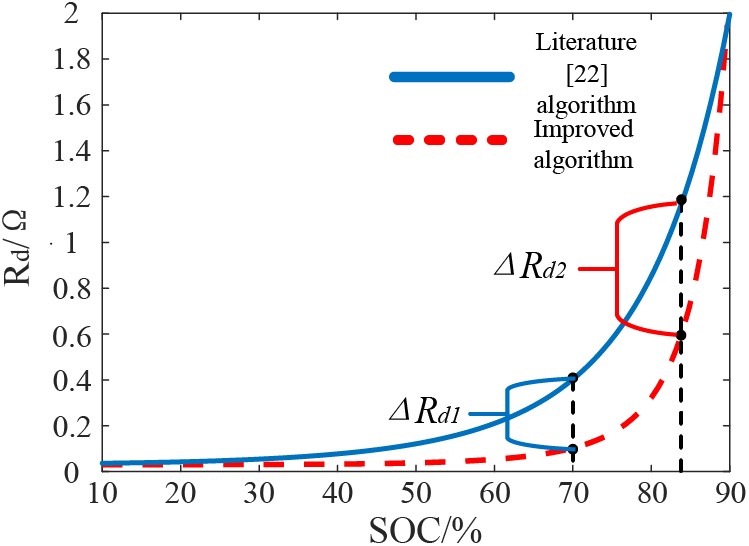
Figure 4: Comparison of convergence speed of droop coefficient Rd algorithm
The difference in Rd ladder variation at different SOC values in the mid-equilibrium of this paper’s algorithm is also more obvious compared to the literature [22], which makes the unbalanced power distribution of each ESU more reasonable and improves the SOC equalization speed of ESS in the mid-term.
In the late stage of SOC equalization, Rd converges to the threshold range rapidly, which reduces the power of ESUs with a high SOC value, preventing them from entering the deep charging and discharging region caused by excessive unbalanced power and extending their service life. Moreover, ASOC is a dynamic range value that varies with the SOC of ESUs, facilitates SOC equalization and minimizes bus voltage deviation.
Fig. 5 illustrates that the Rd variation trend throughout the SOC equalization period is consistent with Fig. 4. Additionally, the figure demonstrates that increasing Rd leads to an increase in the virtual impedance value it represents, thereby influencing the output current of the energy storage converter and causing it to shift. This shift triggers steady-state bus voltage deviations during later stages of control, potentially compromising voltage quality at the common point. Consequently, implementing secondary control measures to counteract bus voltage deviations is essential.

Figure 5: Improved droop control Rd change trend with SOC
The selection range of the sag coefficient is shown in formula (8).
where ibmin and ibmax are the maximum and minimum current output from each ESU to the DC bus terminal, ΔUbmin and ΔUbmax are the minimum and maximum deviation values of ESU port voltage, respectively. Bring it into formula (7) to get the maximum Rdmax and minimum Rdmin values of Rd.
Define SOC as
where SOC, SOC(0), CB, and iL are the current SOC, initial SOC, battery capacity, and output current of the ESU, respectively. It can be seen that the current change value of distributed power capacity is
It is also known that
where UB is the port output voltage of the ESU;
where
where ΔSOC is the SOC change of the ESU within 0~t; t is the time of calculating SOC;
when formula (14) is derived, according to formulas (7), (14) can be converted to
when equalizing, the initial value of SOC of distributed power supply can be determined by the formulas (6) and (14).
Therefore, formula (13) can be converted into
The SOC value of each ESU is calculated according to the formula (17), and the droop coefficient of dynamic change is obtained by bringing it into the formula (18) until Rd stops changing when the SOC of each ESU approaches. It can be seen from formula (6) that when the ΔU positive and negative sizes change, it is necessary to continue to change Rd.
The control principle block diagram of the ESS is shown in Fig. 6. The SOC value of the current ESU is calculated by using formulas (8) to (17) through the battery capacity and current equivalence, and Rd is calculated by substituting into formula (7). Then it enters the droop controller and outputs PWM to B-DC with voltage and current double closed-loop.

Figure 6: Control principle of energy storage system
when Pload<Ppv, and at this time Pbes_max < ΔP, to prevent excessive fluctuation of bus voltage under this condition, it will no longer enter the primary section I control. ESS will directly participate in the voltage stabilization control in the constant power Pbesn mode, as shown in Fig. 7, and enter the primary Section II control after a set time tdelay. The PV will enter the droop control mode from MPPT, reduce its output power, and realize the stable operation of the DC microgrid.

Figure 7: Constant power control principle of energy storage
The maintenance time tdelay shall meet the following requirements:
where Xsocn1 is the charging threshold of the state of charge; PBes_max is the maximum power of the ESS; ΔPBes_max is the maximum change value of ESS power; PBesn is the rated power of the ESS.
Since PBes_max ≥ PBesn to use the ESS with maximum efficiency, it is necessary to set the Xsocn1 value close to SOCmax, get PBes_max/[(SOCmax − Xsocn1)PBesn] ≥ 1. Then formula (19) is obtained:
The overall control process is as follows: the expected I* value of the current loop obtained by dividing PBesn the DC bus voltage value Udc brought it into the PI controller, and the output PWM is also sent to the energy storage converter B-DC.
3.2 Primary Section II Voltage Stabilization Control Strategy
3.2.1 PV System Operation and Control
In a DC microgrid system, ESU and PV are the two key components. To achieve power balancing and voltage stability, these two components must be effectively controlled and managed. In this section, we discuss the control strategies used in the system, with a particular focus on how the system responds when the SOC of the energy storage battery enters the deep charge and discharge regions.
Section II control: The control of the primary II sections of the system for voltage regulation control is an important part of the overall stability of the system. It is responsible for ensuring that the voltage stabilization mode seamlessly switches from the storage to the PV system to meet the power demand of the load. The entire control process is implemented as follows.
In this paper, the PV system utilizes both variable step size MPPT control and sag control with secondary control P-U curve correction. The PV system is in variable step size MPPT mode under normal operation, and this control algorithm is based on the current voltage and current information of the PV array by adjusting the operating point of the PV array in order to make it work near the maximum power point (MPP). In the initial stage of control, a large step size is selected to quickly approach the maximum power point. As the maximum power point is approached, the step size is gradually reduced to maximize the output power of the PV array by continuously adjusting the operating point. However, after a long time of voltage stabilization the SOC of the ESU will enter the deep charge/discharge range, at which time the ESU exits the voltage stabilization mode to prevent the battery from overcharging and overdischarging resulting in system instability.
But when the storage exits the voltage stabilization, ΔP will rapidly increase, to solve the increased ΔP, the PV system will switch from MPPT mode to sag control mode to reduce its operating power to meet the power balance requirements. However, when the residual power ΔP << Pload and the main bus voltage fluctuates, it is necessary to disconnect the non-critical load to reduce the load power to eliminate the unbalanced power ΔP and achieve the DC bus voltage stabilization.
However, this control strategy has some problems, such as frequent switching between voltage stabilization and droop control modes, which can reduce the stability of the overall system control and the lifetime of the ESU. To avoid this situation and to improve the stability of the overall system control and the lifetime of the ESU, charge state thresholds Xsocn1 and Xsocn2 are added to the control strategy, which can effectively cause the ESU to exit from the fully coordinated control before the lithium battery enters the deep charge and discharge state. After the ESU exits, the PV system enters using droop control.
The state of charge thresholds Xsocn1 and Xsocn2 are set based on the characteristics of the lithium battery, such as its charge and discharge curves, voltage, and current limits. The state of charge thresholds can also be adjusted based on load power requirements and ambient temperature to ensure that the system operates efficiently under different operating conditions. The sag characteristics of PV:
where Uref refers to the reference value of bus voltage after secondary control correction; Rdpv is the sag coefficient of PV.
The droop control principle of the PV unit is shown in Fig. 8. First, the difference between the bus voltage Udc and the bus voltage rating U* is collected and brought into the secondary control. The voltage P-U curve is corrected using the three-loop control structure, and the corresponding PWM signal is generated to enter the droop control link.

Figure 8: PV sag control with the introduction of secondary control
It can be seen from Fig. 8:
where Kp and Ki are the parameters of the PI controller in secondary control.
Due to the inevitable defect of traditional sag control, that is, the existence of virtual impedance, the bus voltage Udc will shift to a certain extent and accumulate with the increase of time and current, which will cause interference to the stable internal operation of the microgrid. Therefore, adding a two-stage control after the system enters the stable state is proposed to realize the P-U curve correction of PV and ESU and reduce the steady-state bus voltage deviation caused by virtual impedance.
The control block diagram is shown in Fig. 9. Calculate the difference between Udc and U*, send it to the PI link to get the compensation amount of U*, and combine this value with the public control link of PV and ESS in the later stage to form a three-PI structure to realize the P-U curve correction of ESU and PV, and reduce the voltage deviation.

Figure 9: Secondary control block diagram
The specific principle of secondary control is shown in Fig. 10. The solid line in Fig. 10a shows the P-U characteristic curve when the battery is normally discharged, and A1 is the normal operating point of the ESU. When Ppv < Pload, the bus voltage drops and point A1 moves to point A2 when power fluctuation occurs in the system. When the primary control completes the suppression of voltage fluctuations, the secondary control starts working to dynamically correct U* on each ESU. The bus voltage is increased by controlling the capacitor discharge on the bus, and point A2 moves to point A3, and the ESU finally absorbs the power released by the capacitor until the bus voltage is stabilized at the rated value, and the secondary control of the energy storage unit discharge state is completed. Charging state as shown in Fig. 10b, when Ppv > Pload, the bus voltage rises, C1 moves to C2, then the secondary control work, control capacitor charging on the bus to reduce the bus voltage, C2 moves to C3, that is, the ESU charging mode secondary control is complete.

Figure 10: Schematic diagram of secondary control principle
The secondary control principle of PV mode is similar to that of energy storage mode, when there is an unbalanced power ΔP, and Ppv < Pload, it is manifested as a drop in bus voltage Udc, B1 moves to B2, and then the secondary control starts to work, and the control of capacitor discharging on the PV side raises the bus voltage Udc, and B2 moves to B3, the secondary control is completed in the working condition of PV mode (Ppv < Pload). Fig. 10d shows the Ppv > Pload condition in PV mode, the principle is the same as in Fig. 10b, the secondary control completes the correction of the P-U curve of the PV side under this condition (Ppv > Pload) by controlling the charging of the capacitor on the PV side.
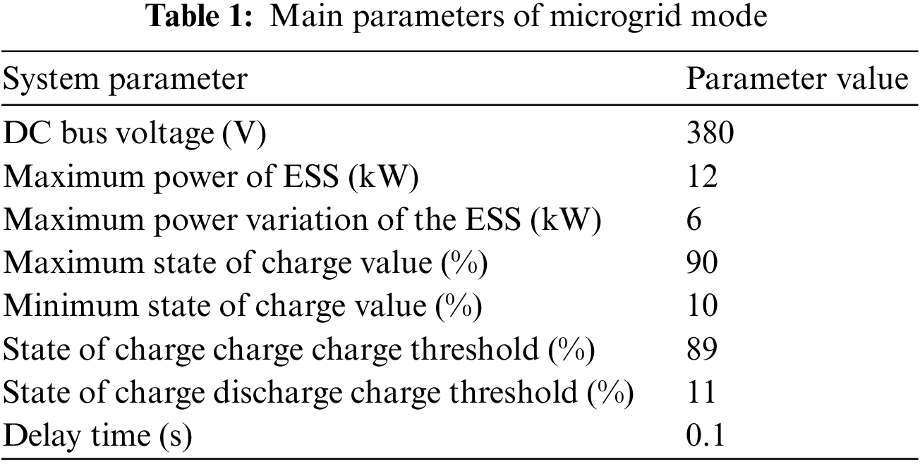
Build relevant models in the simulation software, and verify the bus voltage fluctuation amplitude, voltage offset, and SOC balance of the three groups of ESUs in the entire independent DC microgrid model under different working conditions, respectively, the ESU charging and discharging state transition caused by the independent stable charging and discharging state, load, and power disturbance at the photovoltaic end, and compare the control effect with the strategy proposed in the literature [22], The correctness and effectiveness of the improved droop control proposed in this paper are verified. The specific parameters are shown in Table 1.
4.1 Charge and Discharge of ESS under Primary Section I Control
The simulation is carried out for the ESU under the condition of stable charging or discharging under the primary Section I control mode, and the comparison and analysis are made with the control strategy proposed in the literature [22] under the same working conditions, such as SOC balance, bus voltage fluctuation, and steady-state bus voltage deviation.
The simulation waveform results of ESU stable discharge are shown in Fig. 11. Currently, the ESU3 with the lowest SOC value is charged at the maximum power.

Figure 11: The first section of the improved algorithm controls the power, SOC waveform, and DC bus voltage waveform of the ESU during stable charging: (a) Power of ESUs; (b) SOC of ESUs; (c) DC bus voltage
It can be seen from Fig. 11a that at the initial stage of load distribution, ΔPESU was about 1.5 kW, and by 120 s, it was reduced to 0.15 kW, which achieved power convergence, and the SOC difference between ESU1 and ESU3 was also reduced from 20% to 0.05%.
The simulation change of the stable charging state in literature [22] is shown in Fig. 12. Due to the large deviation of ∆SOC, the power has not started to converge. The maximum power difference of ESU is increased from 0.55 kW to about 1.1 kW, and ∆SOC is reduced from 20% to about 12%. The steady-state bus voltage deviation gradually increases to about 7.3 V during this process

Figure 12: The first section of the unimproved algorithm controls the power, SOC waveform, and DC bus voltage waveform of the ESU during stable charging: (a) Power of ESUs; (b) SOC of ESUs; (c) DC bus voltage
Through the comparison of ESU under stable charging conditions, it can be seen that the improved droop control strategy proposed in this paper, ΔPESU difference is large, which is more conducive to the rapid equalization of SOC, and the voltage deviation is also significantly smaller at the later stage of control.
It can be seen from Fig. 13 that at the initial stage of load distribution power, ΔPESU was about 5.5 kW, and by the time of 70 s, it was reduced to 0.3 kW, which achieved power convergence, while the SOC difference between ESU1 and ESU3 decreased from 20% to about 0.2%.

Figure 13: The first section of the improved algorithm controls the power, SOC waveform, and DC bus voltage waveform of the ESU during stable discharging: (a) Power of ESUs; (b) SOC of ESUs; (c) DC bus voltage
Fig. 13c also shows that due to the secondary control, the steady-state bus voltage deviation in the stage of stable discharge of primary I control energy storage does not change, which overcomes the problem of excessive steady-state bus voltage deviation in the traditional droop control. The time for SOC discharge equalization of three groups of batteries is shortened.
The simulation change of stable discharge state in literature [22] is shown in Fig. 14. At 30 s, the ESU power difference decreased from about 3.5 kW to about 1.82 kW, ΔSOC from 20% to about 9.34%, and the bus voltage difference gradually increases to about 7.5 V from 21.4 s.

Figure 14: The first section of the unimproved algorithm controls the power, SOC waveform, and DC bus voltage waveform of the ESU during stable discharging: (a) Power of ESUs; (b) SOC of ESUs; (c) DC bus voltage
It can be seen from the comparison that the improved control strategy proposed in this paper can achieve SOC equalization in the rapid convergence of Rd and significantly reduce the steady-state bus voltage offset during the stable discharge of ESU.
4.2 Charge and Discharge of ESS under Primary Section I Control
The influence of load power fluctuation and photovoltaic power fluctuation on the system’s stable operation caused by the ESU changing from a charging state to a discharging state is analyzed by simulation.
Load power fluctuation is shown in Fig. 15. The photovoltaic output power is about 4.5 kW, and the load power fluctuates at 20 s, and the load power rises from 0.5 to 14.5 kW. Due to the ΔP change of the positive and negative relationship, the charging and discharging state of the ESU will change accordingly, and its power will be adjusted rapidly to balance Ppv and Pload to meet the stable operation requirements of the DC microgrid system.

Figure 15: Operation characteristics under load fluctuation: (a) PV output power; (b) Load power; (c) Energy storage power
when it fluctuates, the comparison of SOC waveform changes of ESU is shown in Fig. 16.
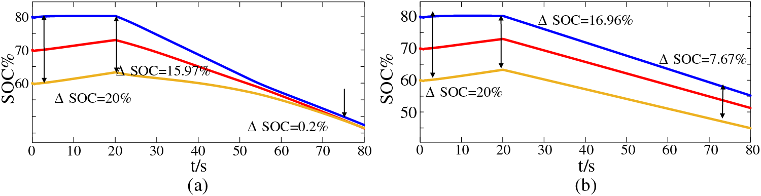
Figure 16: SOC waveform during load fluctuation: (a) Improved algorithm SOC waveform; (b) Unimproved algorithm SOC waveform
According to Fig. 16a, at 0 s, the SOC value of each ESU is the initial set value, and the ratio of ESU1 and ESU3 is 20%. At the 20 s, ΔSOC = 15.97%, and at this time, the load power fluctuates, the ESS starts to redistribute power, and the charging and discharging status of each ESU starts to change from charging balance to discharging balance. At 80 s = 0.2%, the SOC of each ESU has reached equilibrium.
According to Fig. 16b, at 0 s, the ΔSOC of ESU1 and ESU3 is 20%. At 20 s, ΔSOC = 16.96%; At 80 s, ΔSOC = 7.67%.
Compared with Figs. 16a and 16b, when the load power changes suddenly, the control strategy proposed in this paper can accelerate the convergence of droop coefficient Rd and shorten the duration of SOC equalization.
The comparison of DC bus voltage during fluctuation is shown in Fig. 17. When the load fluctuates, the ESS enters a stable discharge state of section I.

Figure 17: DC bus voltage during load fluctuation: (a) Bus voltage fluctuation; (b) Bus voltage deviation
The maximum voltage fluctuation of the bus is 4.0 V, which is 2.6 V compared with that of literature [22] under the same working condition, and the inhibition effect is improved by about 39.4%. When the system becomes stable, the secondary control begins to work. The capacitance discharge on the DC bus changes the characteristic sag curve of the ESS in the first stage of stable discharge. Finally, the steady-state bus voltage deviation = 0.05 V is significantly lower than the voltage deviation in the literature [22].
However, the simulation results of the control strategy in the literature [22] have no such effect. Fig. 17b shows that the bus voltage deviation is 2.5 V, and due to the defects of traditional sag control, the steady-state bus voltage deviation will continue to increase.
The comparison verifies that the control strategy proposed in this paper can effectively reduce the amplitude of bus voltage fluctuation and the steady-state bus voltage deviation.
The operation characteristics of photovoltaic power fluctuation are shown in Fig. 18.

Figure 18: Operation characteristics under PV fluctuation: (a) PV output power; (b) Load power; (c) Energy storage power
It can be seen from Fig. 18a that the load power is about 6 kW at the beginning, the photovoltaic output power is about 11 kW at the beginning, and the photovoltaic output is reduced to 1.1 kW at the 20 s. At this time, the photovoltaic power fluctuates, and the DC bus voltage fluctuates. At this time, the primary section I control begins to participate. According to the criterion, the ESU quickly changes the control strategy to rapidly stabilize the reduced bus voltage. At the same time, the secondary control starts to work to reduce the steady-state bus voltage deviation further.
Fig. 19 shows the comparison of SOC changes during fluctuations. It can be seen from Fig. 19a that at 0 s, the SOC value of each ESU is the initial set value, and the ΔSOC of ESU1 and ESU3 is 20%. At the 20 s, ΔSOC = 15.93%, and at this time, PV fluctuates, and the charging and discharging state of each ESU begins to change from charging balance to discharging balance. At 100 s, the balance of three groups of ESUs has been completed.
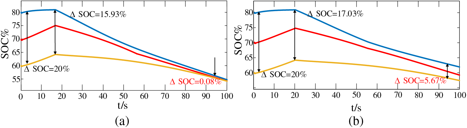
Figure 19: SOC waveform during photovoltaic fluctuation: (a) Improved algorithm SOC waveform; (b) Unimproved algorithm SOC waveform
Compared with Fig. 19b, the improved droop control algorithm is not used, and at 20 s, ΔSOC = 17.03%, at 100 s, ΔSOC = 5.67%. Through comparison, it can be seen that the improved droop control strategy can speed up the convergence of Rd and the speed of SOC equalization when the PV power fluctuates.
Fig. 20 compares DC bus voltage when the photovoltaic power fluctuates.

Figure 20: DC bus voltage waveform during photovoltaic fluctuation. Bus voltage: (a) Bus voltage fluctuation; (b) Bus voltage deviation
when the photovoltaic power fluctuates, the maximum voltage fluctuation of the bus reaches 2.9 V, and the suppression effect of voltage fluctuation amplitude of 5.1 V in the literature [22] is improved.
when the bus voltage fluctuation is stable, the secondary control starts to work, and the final voltage deviation ΔUdc = 0.1 V is significantly reduced compared with the literature [22] voltage deviation = 1.9 V.
By comparing PV power mutation, bus voltage fluctuation amplitude, and voltage deviation, the effect of reducing bus voltage fluctuation amplitude is increased by 43.1% by adopting an improved sag control strategy. The steady-state bus voltage deviation can be significantly reduced compared with the literature [22].
This paper investigates the SOC automatic compensation strategy of ESUs considering DC bus voltage support. The proposed strategy addresses the problem of excessive steady-state bus voltage deviation during voltage stability caused by virtual impedance in traditional droop control, accelerates SOC balancing and reduces bus voltage variations due to load and photovoltaic power variations. The main research elements are:
(1) To improve the convergence speed of the sag coefficient Rd and speed up SOC equalization. The primary section I controller quickly calculates Rd based on the SOC value of each ESU to achieve SOC compensation and reduce voltage fluctuation. Increases the voltage fluctuation suppression effect by approximately 39.4% for load power changes and 43.1% for photovoltaic power changes. When the ESU enters the deep charge/discharge region, it switches to primary segment II control to eliminate unbalanced power through PV voltage regulation and further suppress bus voltage disturbances.
(2) To overcome the limitations of traditional droop control, secondary control is introduced above the primary control to correct the P-U curve of ESU and PV and minimize the effect caused by virtual impedance. The proposed strategy can significantly reduce the voltage deviation when a power mutation occurs in the system, with ΔUdc only 0.01~0.1 V.
In summary, the proposed SOC auto-balancing strategy has viable applications in DC microgrids such as renewable energy systems, electric vehicle charging stations, and data centers. These systems require stable and efficient operation and the proposed strategy can help achieve this by reducing voltage deviations and improving SOC equalization. In addition, the secondary control introduced in the proposed strategy can minimize the impact of virtual impedance and improve the overall performance of the system. It is suggested that future research focus on further improving the existing strategies and investigating the effectiveness of these strategies for DC microgrid systems in grid-connected mode.
Acknowledgement: The authors acknowledge the support to “Tianyou Innovation Team” of Lanzhou Jiaotong University for their support.
Funding Statement: This research was supported by the National Natural Science Foundation of China (No. 52067013), the Natural Science Foundation of Gansu Province (No. 20JR5RA395) as well as the Tianyou Innovation Team of Lanzhou Jiaotong University (TY202010).
Author Contributions: The authors confirm their contribution to the paper as follows: Study conception and design: Jingjing Tian, Shenglin Mo, Feng Zhao, Xiaoqiang Chen. Data collection: Jingjing Tian, Feng Zhao, Xiaoqiang Chen. Analysis and interpretation of result: Jingjing Tian, Shenglin Mo, Feng Zhao. Draft manuscript preparation: Jingjing Tian, Shenglin Mo. All authors reviewed the results and approved the final version of the manuscript.
Availability of Data and Materials: Data supporting this study are included within the article.
Conflicts of Interest: The authors declare that they have no conflicts of interest to report regarding the present study.
References
1. Xu, X. N., Zhou, X. S. (2018). Control strategy for smooth transfer between grid-connected and island operation for the microgrid. High Voltage Engineering, 44(8), 2754–2760 (In Chinese). https://doi.org/10.13336/j.1003-6520.hve.20180731036 [Google Scholar] [CrossRef]
2. Lotel, H., Khodaei, A. (2017). AC versus DC microgrid planning. IEEE Transactions on Smart Grid, 8(1), 296–304. https://doi.org/10.1109/TSG.2015.2457910 [Google Scholar] [CrossRef]
3. Duan, J., Wang, C., Xu, H. (2019). Distributed control of inverter-interfaced microgrids based on consensus algorithm with improved transient performance. IEEE Transactions on Smart Grid, 10(3), 1301–1312. https://doi.org/10.1109/TSG.2017.2762601 [Google Scholar] [CrossRef]
4. Li, X. L., Guo, L., Wang, C. S. (2016). Key technologies of DC microgrids: An overview. Proceedings of the CSEE, 36(1), 2–17 (In Chinese). https://doi.org/10.13334/j.0258-8013.pcsee.2016.01.001 [Google Scholar] [CrossRef]
5. Wang, C. S., Li, W., Wang, Y. F. (2017). DC bus voltage fluctuation classification and restraint methods review for DC microgrid. Proceedings of the CSEE, 37(1), 84–98 (In Chinese). https://doi.org/10.13334/j.0258-8013.pcsee.160807 [Google Scholar] [CrossRef]
6. Wu, Q. F., Sun, X. F., Wang, Y. N. (2018). A distributed control strategy for SOC balancing of distributed energy storage systems in the microgrid. Transactions of China Electrotechnical Society, 33(6), 1247–1256 (In Chinese). https://doi.org/10.19595/j.cnki.1000-6753.tces.170436 [Google Scholar] [CrossRef]
7. Mi, Y., Ji, H. P., He, X. T. (2018). Adaptive hierarchical coordinated control of multi-energy storage in isolated DC microgrid. Proceedings of the CSEE, 38(7), 1980–1989 (In Chinese). https://doi.org/10.13334/j.0258-8013.pcsee.170948 [Google Scholar] [CrossRef]
8. Huang, W., Abu, Q. J. (2015). Energy sharing control scheme for state-of-charge balancing of distributed battery energy storage system. IEEE Transactions on Industrial Electronics, 62(5), 2764–2776. https://doi.org/10.1109/TIE.2014.2363817 [Google Scholar] [CrossRef]
9. Manandhar, U., Tummuru, N. R., Kollimalla, S. K. (2018). Validation of faster joint control strategy for battery-and super capacitor-based energy storage system. IEEE Transactions on Industrial Electronics, 65(4), 3286–3295. https://doi.org/10.1109/TIE.2017.2750622 [Google Scholar] [CrossRef]
10. Meng, M. C., Lu, S. C., Lu, Y. Z. (2017). Coordinated control based on power hierarchy for DC microgrid. Electric Power Automation Equipment, 37(4), 30–37 (In Chinese). https://doi.org/10.16081/j.issn.1006-6047.2017.04.005 [Google Scholar] [CrossRef]
11. Mi, Y., Cai, H. Y., Yuan, M. H. (2019). Dynamic distribution method of current load for distributed energy storage system in DC microgrid. Electric Power Automation Equipment, 39(10), 17–23 (In Chinese). https://doi.org/10.16081/j.epae.201909007 [Google Scholar] [CrossRef]
12. Lu, X. N., Sun, K., Huang, L. P. (2013). Dynamic load power sharing method with the elimination of bus voltage deviation for energy storage systems in DC microgrids. Proceedings of the CSEE, 33(16), 37–46+20 (In Chinese). https://doi.org/10.13334/j.0258-8013.pcsee.2013.16.013 [Google Scholar] [CrossRef]
13. Lu, X., Sun, K., Guerrero, J. M. (2012). SOC-based droop method for distributed energy storage in DC microgrid applications. IEEE International Symposium on Industrial Electronics, pp. 1640–1645. Hangzhou, China. https://doi.org/10.1109/ISIE.2012.6237336 [Google Scholar] [CrossRef]
14. Lu, X., Sun, K., Guerrero, J. M. (2014). State-of-charge balance using adaptive droop control for distributed energy storage systems in DC microgrid applications. IEEE Transactions on Industrial Electronics, 61(6), 2804–2815. https://doi.org/10.1109/TIE.2013.2279374 [Google Scholar] [CrossRef]
15. Dragicevic, T., Guerrero, J. M., Vasquez, J. C. (2014). Supervisory control of an adaptive-droop regulated DC microgrid with battery management capability. IEEE Transactions on Power Electronics, 29(2), 695–706. https://doi.org/10.1109/TPEL.2013.2257857 [Google Scholar] [CrossRef]
16. Yu, M., Wang, Y., Li, Y. G. (2017). Virtual inertia control of hybrid energy storage in DC microgrid based on the predictive method. Power System Technology, 41(5), 1526–1532 (In Chinese). https://doi.org/10.13335/j.1000-3673.pst.2016.1947 [Google Scholar] [CrossRef]
17. Li, P. C., Zhang, C. J., Yuan, R. R. (2017). Load current sharing method of distributed energy storage systems by improved SOC drooping control. Proceedings of the CSEE, 37(13), 3746–3754 (In Chinese). https://doi.org/10.13334/j.0258-8013.pcsee.161527 [Google Scholar] [CrossRef]
18. Lu, X., Sun, K., Guerrero, J. M. (2015). Double-quadrant state-of-charge-based droop control method for distributed energy storage systems in autonomous DC microgrids. IEEE Transactions on Smart Grid, 6(1), 147–157. https://doi.org/10.1109/TSG.2014.2352342 [Google Scholar] [CrossRef]
19. Lu, X., Guerrero, J. M., Sun, K. (2014). An improved droop control method for DC microgrids based on low bandwidth communication with DC bus voltage restoration and enhanced current sharing accuracy. IEEE Transactions on Power Electronics, 29(4), 1800–1812. https://doi.org/10.1109/TPEL.2013.2266419 [Google Scholar] [CrossRef]
20. Cao, S. K., Ma, X., Wang, G. Y., Lin, X. N., Li, Z. T. (2021). System friendly DC microgrid coordinated control strategy under grid side fault. Chinese Journal of Electrical Engineering, 41(23), 7950–7963 (In Chinese). https://doi.org/10.13334/j.0258-8013.pcsee.201613 [Google Scholar] [CrossRef]
21. Zhang, Y., Meng, R. Q., Wang, Z. (2021). An improved droop control strategy based on a consensus algorithm. Power System Protection and Control, 49(14), 104–111 (In Chinese). https://doi.org/10.19783/j.cnki.pspc.201180 [Google Scholar] [CrossRef]
22. Zhang, L., Yan, K. H., Leng, X. B. (2021). Study on coordinated control strategy of independent DC microgrid based on SOC sag control. Power System Protection and Control, 49(12), 87–97 (In Chinese). https://doi.org/10.19783/j.cnki.pspc.200734 [Google Scholar] [CrossRef]
Cite This Article
 Copyright © 2024 The Author(s). Published by Tech Science Press.
This work is licensed under a Creative Commons Attribution 4.0 International License , which permits unrestricted use, distribution, and reproduction in any medium, provided the original work is properly cited.
 Downloads
 Citation Tools