
 Submit a Paper
 Propose a Special lssue
 Open Access
ARTICLE

Factors Influencing Fracture Propagation in Collaborative Fracturing of Multiple Horizontal Wells
1 Shanxi Key Laboratory of Well Stability and Fluid & Rock Mechanics in Oil and Gas Reservoirs, Xi’an Shiyou University, Xi’an, 710065, China
2 The Second Oil Production Plant, Petro China Changqing Oilfield Company, Qingyang, 745100, China
* Corresponding Author: Yuanyuan Kou. Email:
(This article belongs to the Special Issue: Hydraulic Fracturing Theory and Application for Geo-energy Development)
Energy Engineering 2024, 121(2), 425-437. https://doi.org/10.32604/ee.2023.030196
Received 25 March 2023; Accepted 17 May 2023; Issue published 25 January 2024
 View Full Text
 Download PDF
Abstract
Horizontal well-stimulation is the key to unconventional resource exploration and development. The development mode of the well plant helps increase the stimulated reservoir volume. Nevertheless, fracture interference between wells reduces the fracturing effect. Here, a 2D hydro-mechanical coupling model describing hydraulic fracture (HF) propagation is established with the extended finite element method, and the effects of several factors on HF propagation during multiple wells fracturing are analyzed. The results show that with an increase in elastic modulus, horizontal principal stress difference and injection fluid displacement, the total fracture area and the reservoir stimulation efficiency are both improved in all three fracturing technologies. After a comparison of the three technologies, the method of improved zipper fracturing is proposed, which avoids mutual interference between HFs, and the reservoir stimulation effect is improved significantly. The study provides guidance for optimizing the fracturing technology of multiple horizontal wells.Keywords
Nomenclature
| u | The rate vector |
| NI(x) | The common nodal function |
| αI | The improved freedom degree of the node |
| Fα(x) | The progressive rate function of the tip |
| bIα | The improved freedom degree of the unit node |
| r | The vector |
| θ | The angle |
| f | Tolerance |
| σ | The stress value |
Unconventional resource development is mainly realized by horizontal well massive stimulation. The SRV of a well is increased by stress interference between multiple clusters of fractures. On this basis, multi-well collaborative fracturing is developed [1–3]. Compared with single-well fracturing, multi-well collaborative fracturing can maximize the fracturing operation efficiency. Moreover, the induced stress interference between wells and fractures can enhance the fracture complexity greatly and increase the SRV, and improve the stimulation effect. However, multi-well fracturing causes inter-well interference and fracture interference, which lead to variation in in-situ stress, and further affects the stimulation effect of shale reservoirs [4–7]. Therefore, research on how the interference between wells and clusters affects HF expansion in shale fracturing is needed.
Simultaneous fracturing facilitates increase significant improvement of the operation efficiency. Based on establishing an induced stress field model, Peirce et al. [8–10] proposed a mathematical model for calculating multiple fracture pattern. In view of this mathematical model, numerical simulation research on multi-cluster fracture initiation has been carried out by many domestic and foreign scholars. Sepehri et al. [11–13] studied the effect of interference between clusters on fracture pattern by considering fluid loss and fluid distribution among clusters and optimized the cluster spacing in multi fracture expansion. Li et al. [14,15] found that the less stress difference causes greater fracture deflection when considering the effect of stress difference on fracture expansion. Li et al. [16–18] studied the fracture pattern in synchronous fracturing and alternate fracturing by considering the fracturing fluid properties and engineering parameters, and concluded that stress interference is significant in synchronous fracturing. Li et al. [19,20] considered the effect of natural weak interfaces on fracture expansion and concluded that a low stress difference is favorable for communication of natural weak interface and generation of the complex fracture network. This was followed by the development of the “well factory” model, which resulted in multi-well collaborative fracturing. Zhou et al. [21,22] studied how stress difference, cluster spacing, and well spacing affect HF expansion, and found that improved zipper fracturing realizes a better stimulation effect.
In summary, a lot of effort has been put into study on the effect of inter-well interference on HF pattern, and fracture expansion characteristics in multi-well fracturing is still rarely reported. To understand the characteristics of fracture expansion during multi-well fracturing, a 2D hydro-mechanical coupling fracture expansion model is established with the extended finite element method (XFEM), and the effects of inter-well and inter-fracture interference in three fracturing patterns with various rock mechanics parameters and operation parameters are analyzed. This study provides a theoretical basis for optimization of multi-well fracturing.
To obtain the HF expansion law, the finite element (FE) equation is expressed with the enrichment term. The singularity on the crack tip is described with the progressive rate, and the fracturing surface rate is expressed with the equation of jump method. Thus, the rate vector expressed with the global enrichment is simplified as Eq. (1):
where NI(x) represents the common nodal function; uI represents the vector of the continuous rate in the FE solution;
The jump function is defined as Eq. (2):
The progressive rate
r and θ are the local coordinate system on the crack tip, see Fig. 1.
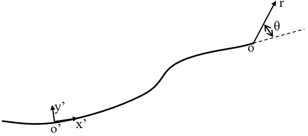
Figure 1: Crack local coordinate system
The fracture expansion criterion applied here is the criterion of maximum principal stress, which is expressed as Eq. (4):
when
That is no initial damage occurs in the enhancement unit under pure compression.
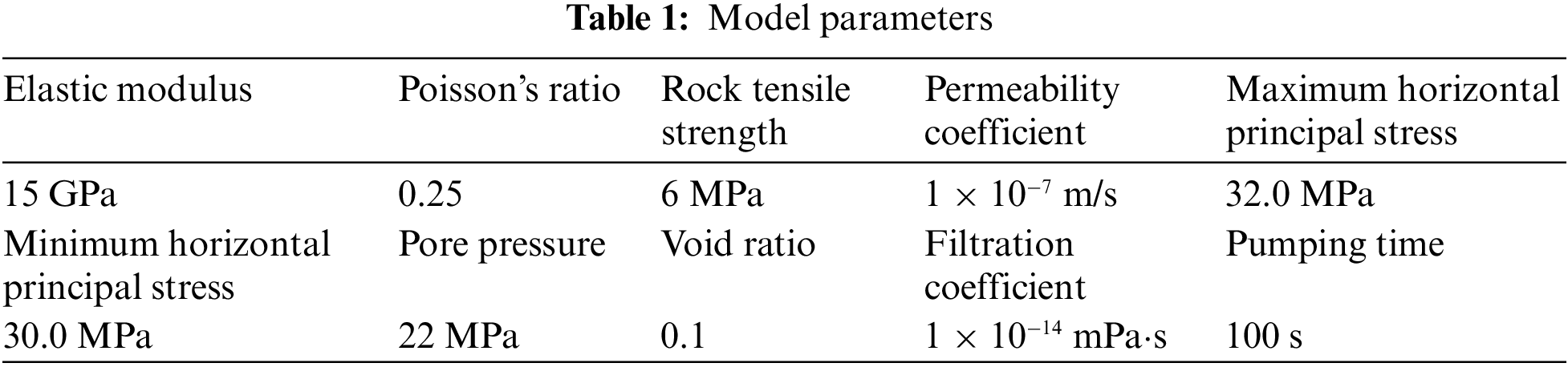
To understand the effect of interference between wells on fracture pattern, a fracture expansion physical model in two boreholes is built with the 2D hydro-mechanical coupling method, as shown in Table 1. The size of the model is 200 m × 200 m, the borehole spacing is 100 m, and the HF spacing is 20 m in a borehole. There are 4 preset fractures in No. 1 borehole, and 3 preset fractures in No. 2 borehole, and all preset fractures are 1 m long. The horizontal minimum principal stress is along the borehole direction, and the maximum horizontal principal stress is perpendicular to the borehole. Rock matrix is meshed with CPE4P method, and the HF is meshed with T2D2 method. The mesh size is 0.5 m, and there are 80,000 meshes. The parameters are listed in Table 1.
Here, the fracture patterns in conventional fracturing with the sequence of 1–3–5–7–2–4–6, zipper fracturing with the sequence of 1–2–3–4–4–5–7–7, and improved zipper fracturing with the sequence of 1–3–2–5–4–7–6 are compared.
Here is a description of the well-type design scheme in the paper. The physical HF expansion model borehole distribution trajectory of dual horizontal wells (improved zipper fracturing) is shown in Fig. 2.
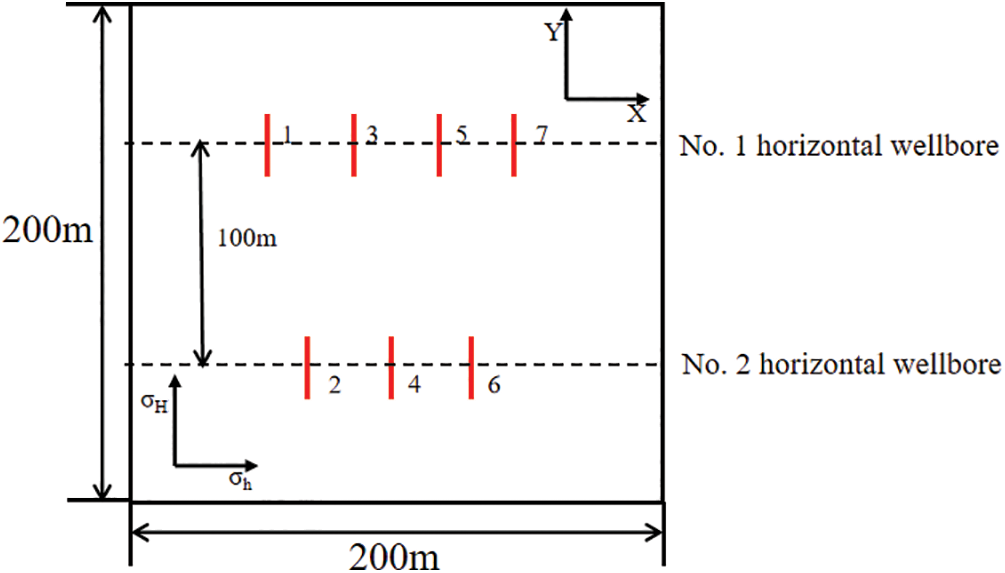
Figure 2: Physical HF expansion model of the borehole distribution trajectory of double horizontal wells
(1) Homogeneous and isotropic strata;
(2) Incompressible Newtonian fluid;
(3) Negligible fluid hysteresis effect;
(4) Negligible effect of the thermal field on rock and fluid properties.
Rock mechanics parameters play a significant role in controlling fracture geometry, especially in fracture expansion. Different rock mechanics parameters, especially elastic modulus and stress difference, have a significant effect on hydraulic fracturing results. At the same time, as a source of fracturing power, the fluid injection rate is a key factor affecting the HF pattern. Finally, the well type also has a direct interference effect on the fracture direction and path. Therefore, take the above two rock mechanics parameters and one fracturing process parameter and well type as research objects, to analyze the effects of different elastic modulus, horizontal principal stress difference, fluid injection rate, and well type on fracture length and reservoir stimulation are analyzed.
The elastic modulus of the rock matrix is set as 15, 20, 25, and 30 GPa, and other parameters are not changed. The total length and total fracture area obtained from three fracturing modes are calculated. The numerical simulation results are shown in Figs. 3–5. The specific parameters of fracturing results are shown in Table 2.
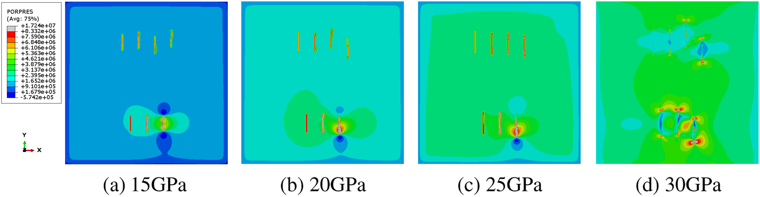
Figure 3: Cloud chart of conventional fracturing HF expansion
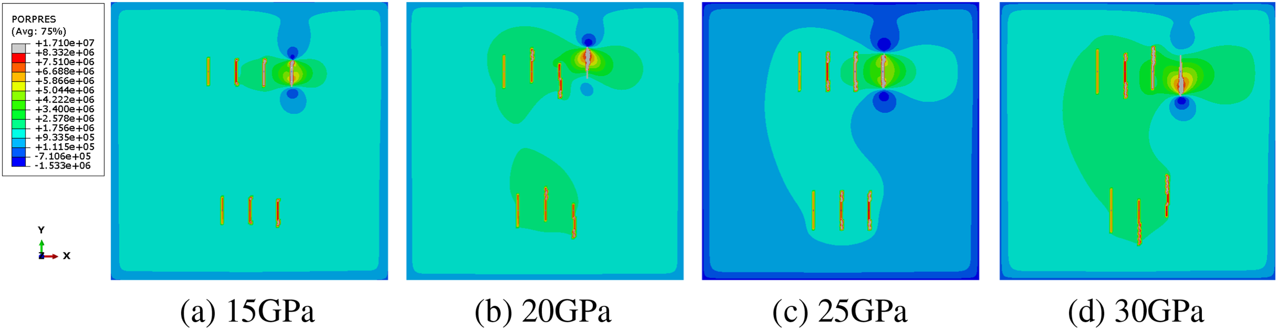
Figure 4: Cloud chart of zipper fracturing HF expansion
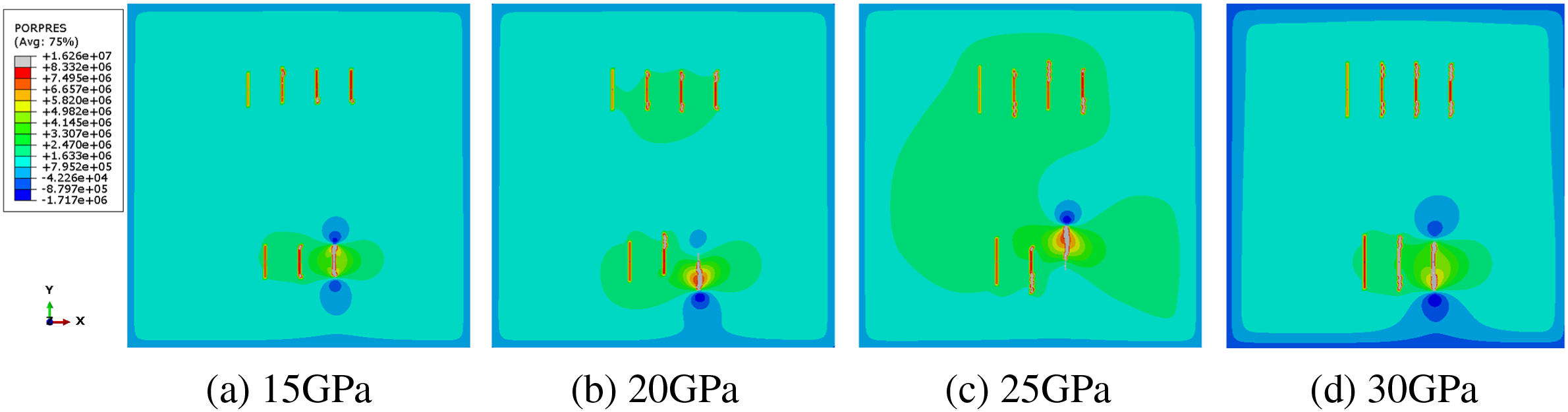
Figure 5: Cloud chart of improved zipper fracturing HF expansion
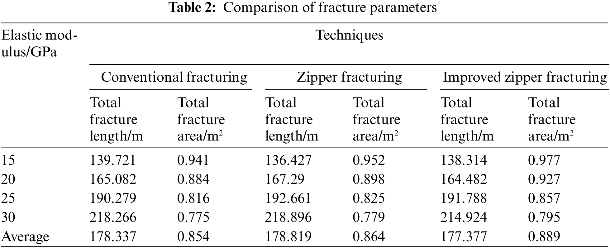
Under the same elastic modulus, the fracture length characteristics are complicated in three fracturing technologies. The main reason is that the length and width of fracture expansion are complicated due to stress interference by other fractures. Only fracture length is not enough to reflect the fracture expansion characteristics and stimulation effect. Based on many attempts and studies, the concept of total fracture area is proposed to characterize the stimulation effect. Total fracture area = fracture length × fracture width and the values of fracture length and fracture width can be obtained by post-processing module in numerical simulation. The total fracture areas calculated in three fracturing technologies are listed in Table 1. It can be seen by analysis of the calculation results that as the elastic modulus increases, the fracture lengths of the three technologies increase, and the fracture widths decrease significantly, which leads to a reduction of the total fracture area and a worse stimulation effect. Under the same elastic modulus, improved zipper fracturing creates the largest fracture total area, i.e., the optimal fracture length-width ratio, followed by the zipper fracturing method, and the stimulation effect of the conventional fracturing method is the poorest. The total fracture area in improved zipper fracturing is 0.889 m2, which is 1.03 times that in zipper fracturing and 1.04 times that in conventional fracturing.
4.2 Horizontal Principal Stress Difference
The horizontal maximum principal stress is kept unchanged, and the minimum horizontal principal stress is reduced. The horizontal principal stress difference is set as 0, 2, and 4 MPa. Other model parameters are not changed. The total fracture length and the total fracture area of three fracturing technologies are calculated, to analyze the effect degree of the horizontal principal stress difference on the fracturing efficiency. The numerical simulation results are shown in Figs. 6–8. The specific parameters of fracturing results are shown in Table 3.
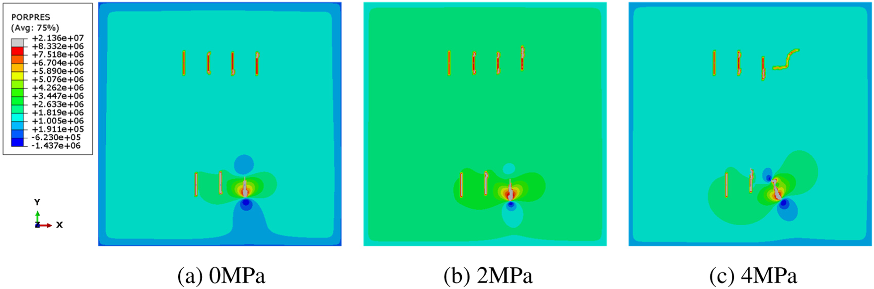
Figure 6: Cloud chart of conventional fracturing HF expansion
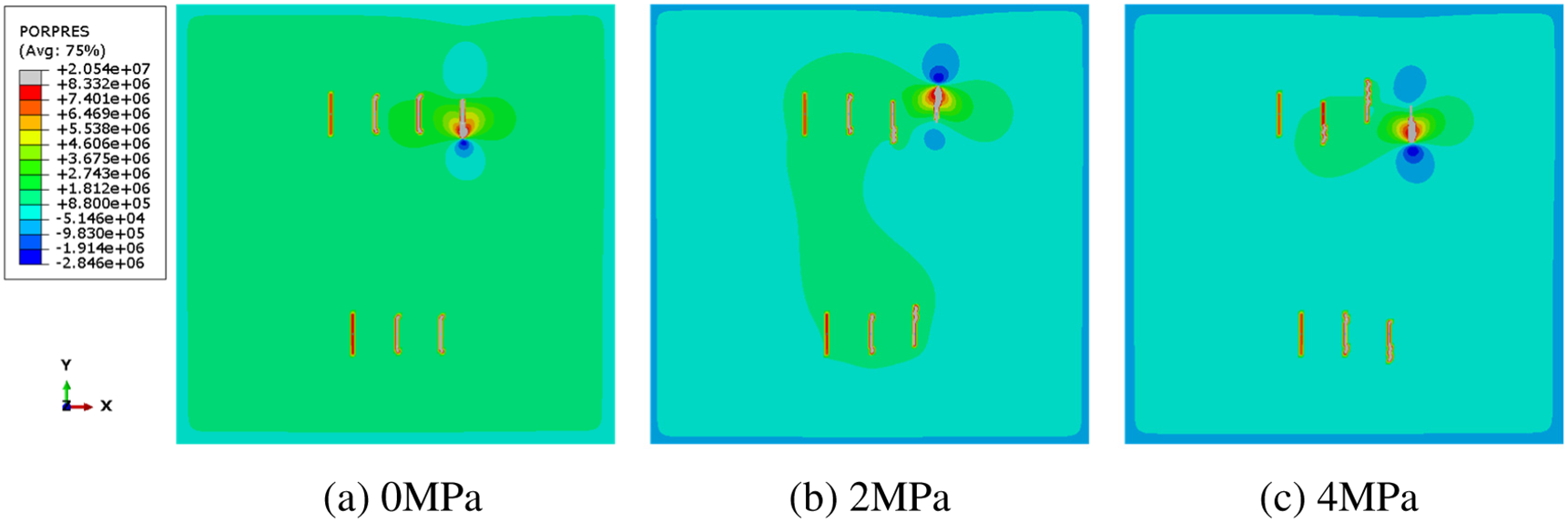
Figure 7: Cloud chart of zipper fracturing HF expansion
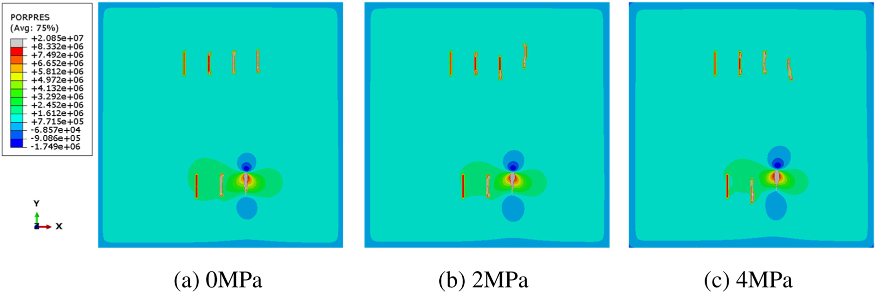
Figure 8: Cloud chart of improved zipper fracturing HF expansion
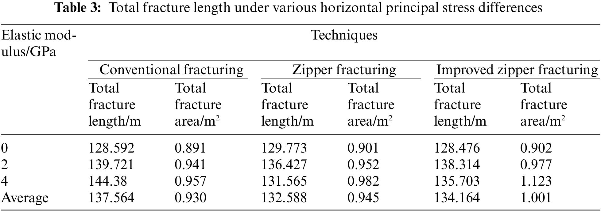
Analysis shows that as the horizontal principal stress difference increases, all three fracturing technologies show an increasing trend. The fracture length of conventional fracturing linearly increases with the increasing stress difference, and it is not observed in the other two methods. Under the same stress difference, the improved zipper fracturing method creates the largest total fracture area, i.e., the optimal fracture length-width ratio and the best reservoir stimulation effect. Under the influence of stress difference, the total fracture area increases alternately for the conventional fracturing method, and zipper fracturing method. When the stress differences are 0 and 2 MPa, the conventional fracturing method creates the largest fracture area. When the stress difference is 4 MPa, zipper fracturing creates the largest fracture area. The total fracture area in improved zipper fracturing is 1.001 m2, which is 1.05 times that in zipper fracturing and 1.08 times that in conventional fracturing. Analysis shows that there is no linear relationship between fracture width and fracture length due to the influence of in-situ stress and fracturing technological measures. And the stress interference between fractures is more complicated. However, the improved zipper fracturing method still shows the best reservoir stimulation effect.
Fluid injection rate has a significant effect on the HF pattern. Fluid injection rate is set as 0.12, 0.24 and 0.36 m3/min, and the other parameters are not changed. The total fracture length and area in three fracturing technologies are calculated. The increment of the total fracture length is calculated. The numerical simulation results are shown in Figs. 9–11. The specific parameters of fracturing results are shown in Table 4.
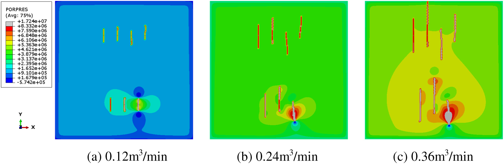
Figure 9: Cloud chart of conventional fracturing HF expansion
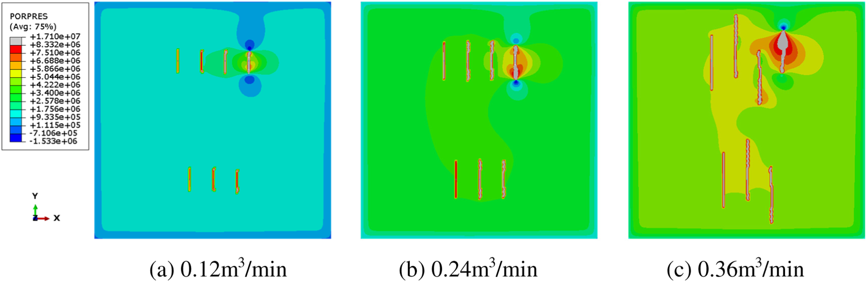
Figure 10: Cloud chart of zipper fracturing HF expansion
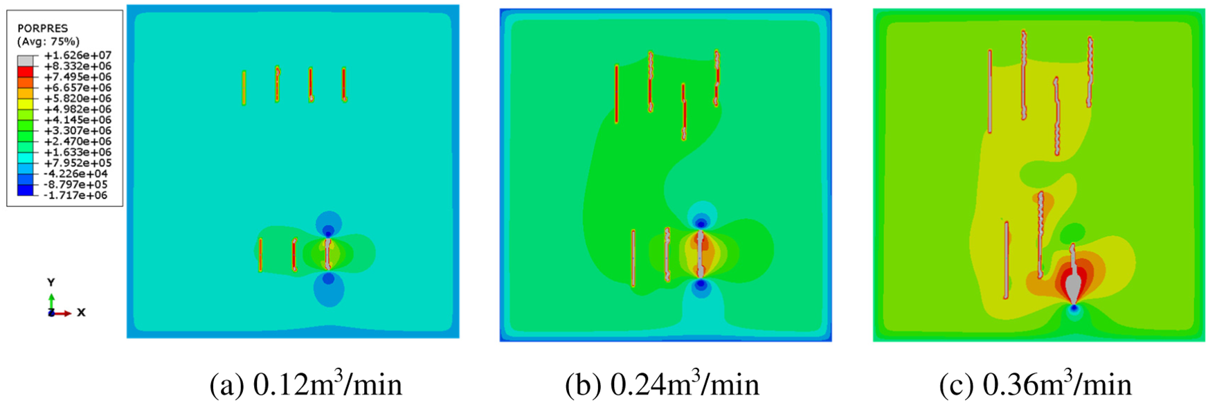
Figure 11: Cloud chart of improved zipper fracturing HF expansion
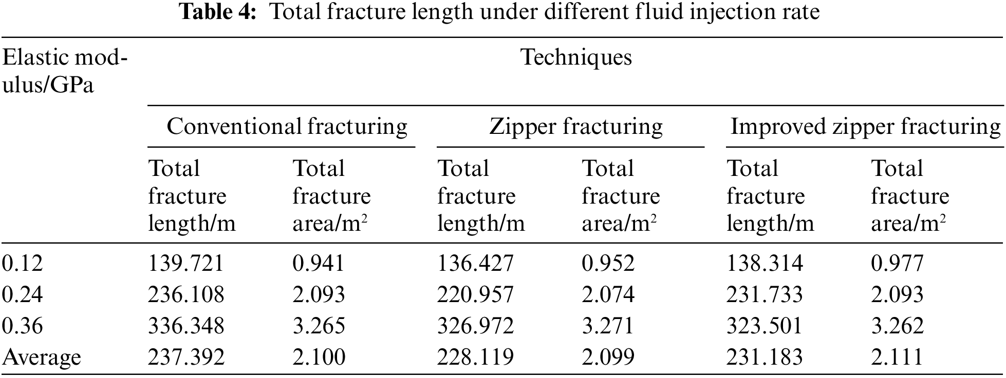
As the fluid injection rate increases, the fracture length and total fracture area in all three fracturing methods show an increasing trend. At the same rate, the conventional fracturing method creates the largest fracture length. When the rate is 0.12 m3/min, the improved zipper fracturing method creates the largest total fracture area, when the rate is 0.36 m3/min, the conventional fracturing method creates the largest total fracture area. The fracturing process sequence and fluid injection rate control the reservoir stimulation efficiency together. On average, the total fracturing area in conventional fracturing is 2.1010 m2, that in zipper fracturing method is 2.099 m2, and that in improved zipper fracturing is 2.100 m2. Under the complex nonlinear law, the reservoir stimulation effect of the three methods is the same.
well type has an important influence on HF expansion. The total fracture length and total area created in three well types were extracted by setting single branching well, double branching well, and triple branching well, with other parameters unchanged. The borehole trajectory design scheme of double branching well is shown in Fig. 2. The borehole trajectory design scheme of a single horizontal well and triple branching horizontal well (Multi-branch well) is shown in Figs. 12 and 13. The numerical simulation results are shown in Fig. 14. The fracturing results are listed in Table 5.
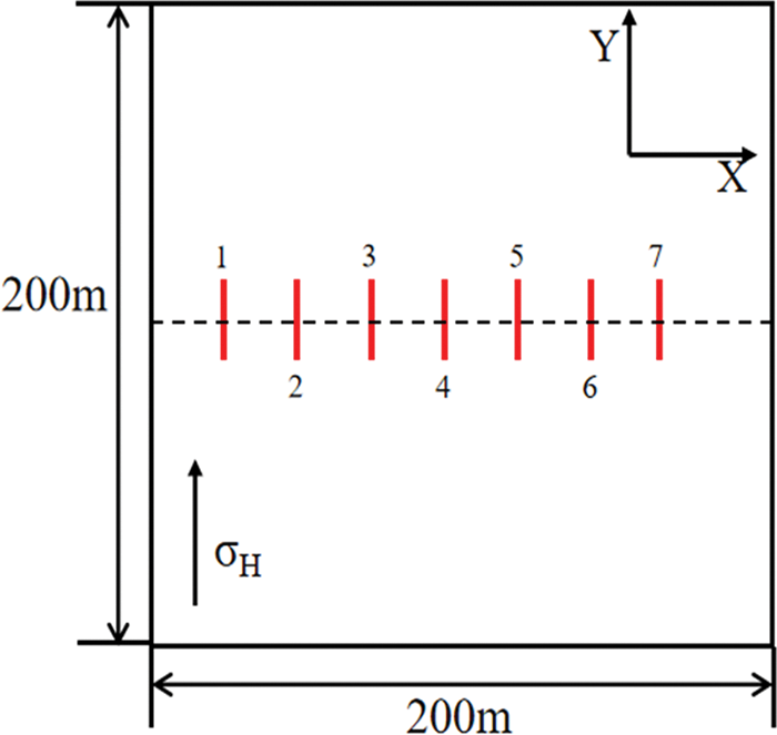
Figure 12: Physical HF expansion model of the borehole distribution trajectory of a single horizontal well
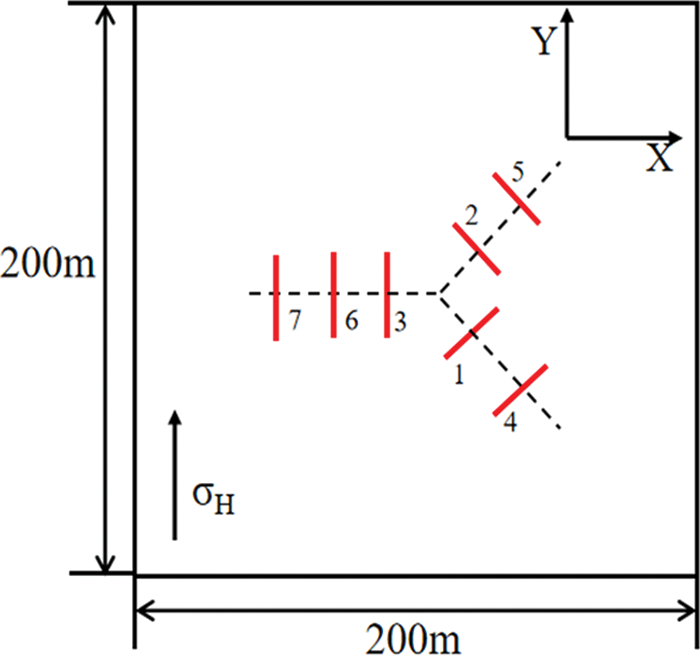
Figure 13: Physical HF expansion model of the borehole distribution trajectory of triple branching horizontal wells
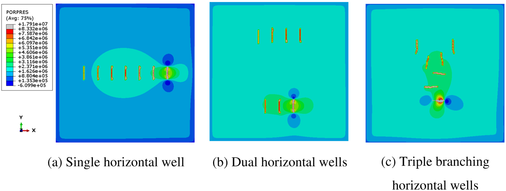
Figure 14: Cloud chart of HF expansion under different well types
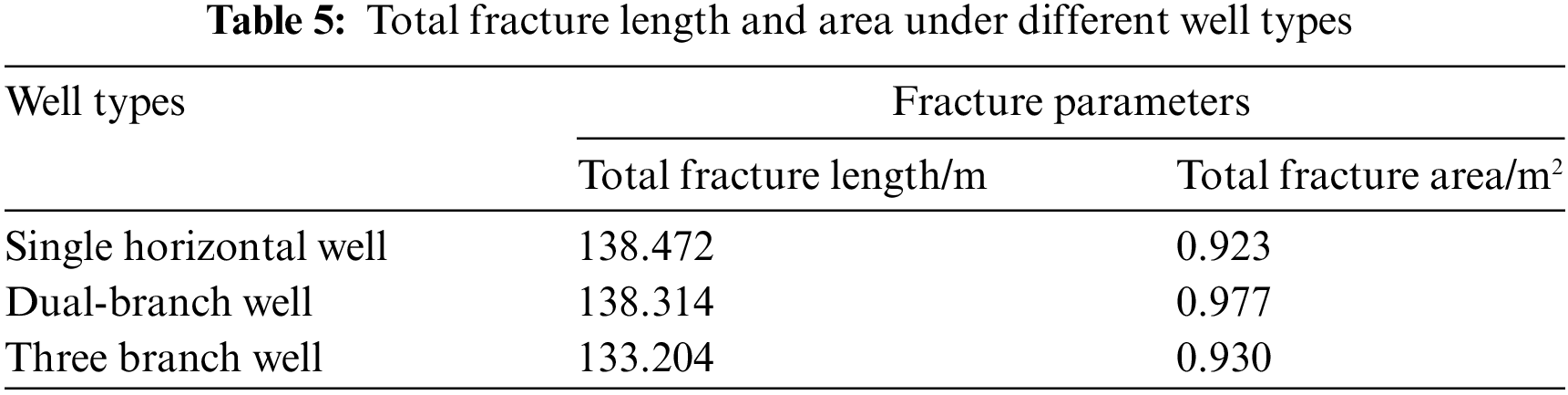
The results show that as the number of branch well increases, the fracture length decreases gradually. The total fracture length decreases by 3.8% from the single horizontal well to the three-branch well. The largest fracture area and the best reservoir stimulation effect are obtained from the dual-branch well. In general, there is no linear relationship between the branch number and the stimulation effect. Under the situation of a triple branching well, the HFs are close to each other, which causes serious stress interference. This clearly reveals the nature that the HF direction and stress interference will bring negative effects on the fracturing efficiency.
Based on the XFE method, a 2D hydro-mechanical coupling model of multi-well fracturing is established to analyze the effects of various factors on total fracture length and total fracture length increment. The understandings are obtained as follows:
(1) An increase in elastic modulus leads to an increase in fracture length and a significant decrease of fracture width in three fracturing technologies, and a decrease in total fracture area and the worse stimulation effect. Under the same elastic modulus, improved zipper fracturing creates the largest total fracture area and the best reservoir stimulation effect, followed by zipper fracturing, and the stimulation effect is worst in conventional fracturing.
(2) An increase in the horizontal principal stress difference leads to an increase in the total fracture area. The fracture length has a linear relationship with the horizontal principal stress difference in conventional fracturing and does not show this linear relationship in zipper fracturing and improved zipper fracturing. Under the same horizontal principal stress difference, improved zipper fracturing creates the largest total fracture area. The effects of the horizontal principal stress difference and stress interference between fractures cause the complex fracture expansion law in conventional fracturing and zipper fracturing.
(3) An increase in fluid injection rate causes a significant increase in the fracture length and total fracture area in three fracturing technologies. At the same rate, conventional fracturing creates the largest fracture length. The total fracture area is restricted by the fracturing sequence and fluid injection rate and does not show an obvious law. The effects of three fracturing technologies are different under different fluid injection rates. This indicates that both fluid injection rate and fracturing method play a key role in controlling the stimulation effect.
(4) An increase in the branch number causes a decrease in the fracture length. The largest fracture area and the best reservoir stimulation effect are obtained in the dual-branch well.
Acknowledgement: The authors wish to acknowledge the financial support received from the National Natural Science Foundation of China, Shaanxi Natural Science Basic Research Program Project, Xi’an Shiyou University Youth Scientific Research and Innovation Team Operation Funds in 2018. We would like to express our appreciation to the other members of the laboratory for the help provided in experiments and language editing.
Funding Statement: This study was funded by Shaanxi Natural Science Basic Research Program Project Study on Liquid Propellant High Energy Gas Fracturing Mechanism in Radial Well Based on Phase Field Method (No. 2019JQ-824). NSFC Projects Evolution Mechanism and Effectiveness Evaluation of Fracture Network Produced by Volume Fracturing with Tighter Clusters in Continental Shale Oil Reservoir (No. 52274040) and Study on Thermal Secondary Pore Evolution and Salt Precipitation Regulation Mechanism in Fire Flooding Reservoirs Based on Multi-field Coupling of Thermal-Flow-Solid-Chemical (No. 52274039); Xi’an Shiyou University Youth Scientific Research and Innovation Team Operation Funds in 2018 Flow Mechanism of Complex Reservoirs and High Efficiency Development and Oil Production Technology (No. 115080020).
Author Contributions: Methodology, G.D.G.; Software, Y.Y.K.; Formal analysis, C.C.; Investigation, G.D.G.; Data curation, B.J.C.; Writing—original draft, B.J.C. and Y.Y.K. All authors have read and agreed to the published version of the manuscript.
Availability of Data and Materials: The data presented in this study are available on request from the corresponding author.
Conflicts of Interest: The authors declare that they have no conflicts of interest to report regarding the present study.
References
1. Wang, Y., Li, X., Wang, J. B., Zheng, B., Zhang, B. et al. (2015). Numerical modeling of stress shadow effect on hydraulic fracturing. Natural Gas Geoscience, 26(10), 1941–1950. [Google Scholar]
2. Chen, P., Liu, Y., Ma, T. S. H. (2014). Status and prospect of multi-well pad drilling technology in shale gas. Petroleum Drilling Techniques, 42(3), 1–7. [Google Scholar]
3. Sobhaniaragh, B., Mansur, W. J., Peters, F. C. (2018). The role of stress interference in hydraulic fracturing of horizontal wells. International Journal of Rock Mechanics and Mining Sciences, 106, 153–164. [Google Scholar]
4. Zheng, H., Pu, C., Xu, E., Sun, C. (2020). Numerical investigation on the effect of well interference on hydraulic fracture propagation in shale formation. Engineering Fracture Mechanics, 228, 106932. [Google Scholar]
5. Simpson, M. D., Patterson, R., Wu, K. (2016). Study of stress shadow effects in Eagle Ford shale: Insight from field data analysis. The 50th US Rock Mechanics/Geomechanics Symposium, pp. 1874–1880. Houston, USA. [Google Scholar]
6. Roussel, N., Sharma, M. (2011). Strategies to minimize frac spacing and stimulate natural fractures in horizontal completions. 11st Annual Technical Conference and Exhibition, pp. 1189–1205. Denver, USA. [Google Scholar]
7. Li, J., Dong, S., Hua, W., Li, X. L., Guo, T. K. (2020). Numerical simulation of temporarily plugging staged fracturing (TPSF) based on cohesive zone method. Computers and Geotechnics, 121, 103453. [Google Scholar]
8. Peirce, A. P. P., Bunger, A. P. P. (2015). Interference fracturing: Nonuniform distributions of perforation clusters that promote simultaneous growth of multiple hydraulic fractures. SPE Journal, 20(2), 384–395. [Google Scholar]
9. Peirce, A. P., Bunger, A. P. (2014). Robustness of interference fractures that promote simultaneous growth of multiple hydraulic fractures. 8th US Rock Mechanics/Geomechanics Symposium, Minneapolis, Minnesota, OnePetro. [Google Scholar]
10. Zhao, J. Z., Chen, X. Y., Li, Y. M., Fu, B. (2016). Simulation of simultaneous propagation of multiple hydraulic fractures in horizontal wells. Journal of Petroleum Science and Engineering, 147, 788–800. [Google Scholar]
11. Sepehri, J., Soliman, M. Y., Morse, S. M. (2015). Application of extended finite element method (XFEM) to simulate hydraulic fracture propagation from oriented perforations. The SPE Hydraulic Fracturing Technology Conference, pp. 37–41. Woodlands, USA. [Google Scholar]
12. Chen, J. B., Wei, B., Xie, Q., Wang, H. Q., Li, T. T. et al. (2016). Simulation of multi-hydro fracture horizontal wells in shale based on the extended finite element method. Applied Mathematics and Mechanics, 37(1), 73–83. [Google Scholar]
13. Bao, J. Q., Liu, H., Zhang, G. M., Jin, J., Cheng, W. (2017). Fracture propagation laws in staged hydraulic fracturing and their effects on fracture conductivities. Petroleum Exploration and Development, 44(2), 281–288. [Google Scholar]
14. Li, J., Dong, S., Hua, W., Yang, Y., Li, X. L. (2019). Numerical simulation on deflecting hydraulic fracture with refracturing using extended finite element method. Energies, 12(11), 2044. [Google Scholar]
15. Xia, X., Cong, X. (2019). Analysis of initiation angle for fracture propagation considering stress interference. Energies, 12(10), 1841. [Google Scholar]
16. Li, J., Xiao, W., Hao, G., Dong, S. M., Hua, W. et al. (2019). Comparison of different hydraulic fracturing scenarios in horizontal wells using XFEM based on the cohesive zone method. Energies, 12(7), 1232. [Google Scholar]
17. Xie, J., Huang, H., Sang, Y., Yu, F., Chen, J. et al. (2019). Numerical study of simultaneous multiple fracture propagation in changning shale gas field. Energies, 12(7), 1335. [Google Scholar]
18. Beugelsdijk, L. J. L., de Pater, C. J., Sato, K. (2000). Experimental hydraulic fracture propagation in a multi-fractured medium. SPE Asia Pacific Conference on Integrated Modelling for Asset Management, Yokohama, Japan. [Google Scholar]
19. Li, J., Dong, S., Hua, W., Li, X. L., Pan, X. (2019). Numerical investigation of hydraulic fracture propagation based on cohesive zone model in naturally fractured formations. Processes, 7(1), 28. [Google Scholar]
20. Li, J., Hua, W., Tang, H., Huang, J. Z., Dong, S. M. et al. (2022). Stress intensity factors and T-stress for an edge fractureed Brazilian disk specimen under diametrically distributed load. Theoretical and Applied Fracture Mechanics, 120, 103402. [Google Scholar]
21. Zhou, D. S., Zheng, P., Yang, J. W., Li, M., Xia, Y. C. et al. (2019). Optimizing the construction parameters of modified zipper fracs in multiple horizontal wells. Journal of Natural Gas Science and Engineering, 71, 102966. [Google Scholar]
22. Tian, W., Li, P. C., Dong, Y., Lu, Z., Lu, D. et al. (2019). Numerical simulation of sequential, alternate and modified zipper hydraulic fracturing in horizontal wells using XFEM. Journal of Petroleum Science and Engineering, 183, 106251. [Google Scholar]
Cite This Article
 Copyright © 2024 The Author(s). Published by Tech Science Press.
This work is licensed under a Creative Commons Attribution 4.0 International License , which permits unrestricted use, distribution, and reproduction in any medium, provided the original work is properly cited.
 Downloads
 Citation Tools