
 Submit a Paper
 Propose a Special lssue
 Open Access
ARTICLE

An Adaptive Control Strategy for Energy Storage Interface Converter Based on Analogous Virtual Synchronous Generator
School of Automation and Electrical Engineering, Lanzhou Jiaotong University, Lanzhou, 730070, China
* Corresponding Author: Jinshuo Zhang. Email:
Energy Engineering 2024, 121(2), 339-358. https://doi.org/10.32604/ee.2023.043082
Received 26 June 2023; Accepted 14 September 2023; Issue published 25 January 2024
 View Full Text
 Download PDF
Abstract
In the DC microgrid, the lack of inertia and damping in power electronic converters results in poor stability of DC bus voltage and low inertia of the DC microgrid during fluctuations in load and photovoltaic power. To address this issue, the application of a virtual synchronous generator (VSG) in grid-connected inverters control is referenced and proposes a control strategy called the analogous virtual synchronous generator (AVSG) control strategy for the interface DC/DC converter of the battery in the microgrid. Besides, a flexible parameter adaptive control method is introduced to further enhance the inertial behavior of the AVSG control. Firstly, a theoretical analysis is conducted on the various components of the DC microgrid, the structure of analogous virtual synchronous generator, and the control structure’s main parameters related to the DC microgrid’s inertial behavior. Secondly, the voltage change rate tracking coefficient is introduced to adjust the change of the virtual capacitance and damping coefficient flexibility, which further strengthens the inertia trend of the DC microgrid. Additionally, a small-signal modeling approach is used to analyze the approximate range of the AVSG’s main parameters ensuring system stability. Finally, conduct a simulation analysis by building the model of the DC microgrid system with photovoltaic (PV) and battery energy storage (BES) in MATLAB/Simulink. Simulation results from different scenarios have verified that the AVSG control introduces fixed inertia and damping into the droop control of the battery, resulting in a certain level of inertia enhancement. Furthermore, the additional adaptive control strategy built upon the AVSG control provides better and flexible inertial support for the DC microgrid, further enhances the stability of the DC bus voltage, and has a more positive impact on the battery performance.Keywords
Nomenclature
| Moments of inertia | |
| Virtual capacitance (F) | |
| Damping coefficient | |
| Droop coefficient | |
| Electromagnetic power (W) | |
| Damping power (W) | |
| The | |
| Photovoltaic output power (W) | |
| Load output power (W) | |
| The angular velocity | |
| Rated angular velocity | |
| Output voltage of AVSG (V) | |
| The rated voltage of AVSG (V) | |
| DC bus voltage (V) | |
| Virtual capacitance current (A) | |
| The | |
| DC bus current (A) | |
| Damping current (A) | |
| Solar irradiance (W/m2) | |
| Inductive current of the battery (A) | |
| State of charge of the battery | |
| Voltage change rate tracking coefficient of | |
| Voltage change rate tracking coefficient of |
In recent years, the issues of energy scarcity and environmental pollution have driven a transition in the generation mode of the power system from traditional centralized power generation to distributed power generation [1,2]. As a type of power system, the DC microgrid has gained widespread attention due to its suitability for large-scale integration of distributed power sources. And compared with the AC microgrid, the DC microgrid does not need to consider factors such as frequency, reactive power, and phase, resulting in higher power supply quality [3].
In the DC microgrid, the power balance among distributed source, energy storage unit, and load ensures the stability of the DC bus voltage, which serves as a critical indicator for the secure and stable operation of the system. The DC microgrid form adopted in this paper is a photovoltaic (PV) and battery energy storage (BES)-integrated DC microgrid. In the microgrid, the PV unit in microgrid usually operates in the maximum power point tracking (MPPT) state [4]. And BES is connected to the DC bus through its interface DC/DC converter, which can smooth out the fluctuations generated by the PV unit and the load, thereby maintaining the power balance in the DC microgrid and the stability of the DC bus voltage. The control strategies of the DC/DC converter of the energy storage interface usually use constant voltage control or droop control. Both proportional-integral (PI)-based control strategies have a positive effect on maintaining the stability of the DC bus voltage. However, due to the lack of inertia and damping of the converter, the voltage stabilization effect of BES is limited and the DC microgrid is still a low-inertia network. Intermittent fluctuations from the PV unit and load switching can result in sudden changes in the DC bus voltage, which significantly impact the stability of the DC microgrid system and the voltage quality [5].
To address the aforementioned issues, experts both domestically and internationally have proposed various types of inertia control strategies, mainly including virtual element control [6–9], virtual DC generator (VDG) control [10–17], and analogous virtual generator (AVSG) control [18–22]. Virtual element control is often used in the form of electronic components for inertial enhancement. Adib et al. proposed an adaptive virtual impedance control strategy to improve system inertia by adjusting the load input impedance [6]. Li et al. [7] used virtual capacitance control to improve the performance of the system transient response, but this control still produced a certain degree of voltage fluctuation during the initial stages of disturbance. Similarly, the research of Ahmed et al. [8,9] also showed that the virtual element inertial control can improve system stability. As a single variable control strategy, virtual element control has a simple structure, but it has relatively poor robustness to system parameter changes or external interference. Therefore, with the evolution of inertia control strategies, multi-variable and higher-performing virtual motor control technologies, including the VDG and the AVSG, have been proposed.
The VDG control simulating the characteristics of the DC generator is used in the interface converter of the DC microgrid side to provide inertia and damping. The VDG control can be applied to the converter of the load side to reduce DC bus voltage fluctuation caused by disturbance of the load [10,11]. He et al. [12] proposed a control strategy applying the VDG control to the source-side converter of the DC microgrid to effectively reduce the influence caused by power fluctuation. Furthermore, as an inertia control strategy, the VDG control is commonly used in the energy storage side of the DC microgrid system. The VDG control not only adjusts the power support function of energy storage devices to fully utilize their performance but also stabilizes the DC bus voltage. Tan et al. [13,14] applied the VDG control to the energy storage interface converter to enhance the inertial support capability and power calming effect of the energy storage unit. However, as a multi-variable control strategy introducing inertia and damping, the VDG control lacks inherent droop characteristics [15–17]. The direct utilization of the VDG control only meets the requirements for maintaining constant voltage control of the energy storage interface converter, while it fails to address the demands of droop control. To impart droop characteristics to the DC bus voltage, which is better suited for accommodating multiple energy storage units in the DC microgrid in the future, the AVSG control strategy is introduced.
By drawing inspiration from the VSG control concept in the AC microgrid, the AVSG control incorporates inertia, damping, and droop characteristics, and has a simple structure. It is well-suited for DC microgrids and demonstrates significant effectiveness in stabilizing DC bus voltage. Cao et al. [18] proposed a variable-structure AVSG control strategy for DC microgrid multi-port converters. Zhu et al. [19,20] designed two AVSG control strategies for the power electronic converters and both control strategies have shown excellent voltage regulation performance. The converter controlled by the AVSG can smooth the voltage fluctuation in the DC microgrid to a certain extent. However, during instances of large external power disturbances, especially when random fluctuations arise within the microgrid, the fixed inertia and damping parameters limit the flexibility of the DC microgrid’s inertia. As a result, there may still be a large fluctuation of the DC bus voltage in the transient process, affecting the stability of the system. To tackle this issue, the parameter adaptive control method is introduced and has been proven effective in improving the flexibility of the DC microgrid’s inertia. At present, there have been some research results on the AVSG adaptive control. Cao et al. [21,22] employed two adaptive control approaches for inertia and damping based on distinct AVSG control structures, and both adaptive controls exhibited certain improvements in comparison to the original control. However, Cao et al. [21] solely focused on the impact of load fluctuation, and the effectiveness of the adaptive control is unsatisfactory. Zeng et al. [22] considered the impacts of the photovoltaic power and load power under the step conditions, but the designed adaptive control lacks universality and presents complexity. In reality, scenarios involving random power fluctuations more closely resemble the actual operating conditions of the DC microgrid. Examples include short-term random shifts in solar irradiance and frequent load switching, both of which require consideration.
Therefore, according to the above analysis, the study conducted encompasses the following:
(1) Through theoretical analysis and equation derivation, the AVSG control is introduced into the DC/DC converter of the BES interface in the DC microgrid.
(2) By analyzing the inertia effects of the AVSG control parameters that meet system stability, a universally applicable and simple adaptive parameter control method is designed.
(3) In the scenarios involving both step power fluctuation and random power fluctuation of the PV and load, the correctness and effectiveness of the AVSG adaptive control strategy are proved. Furthermore, the role of the voltage rate of change tracking coefficient in AVSG adaptive control is discussed.
2 Structure of DC Microgrid with PV and BES
The DC microgrid in this study comprises the photovoltaic (PV) unit, the battery energy storage (BES) unit, the load unit, and the corresponding interface converters, as illustrated in Fig. 1. The PV unit operates in the MPPT mode to output the photovoltaic power. The load units are connected to the DC bus and output the load power.
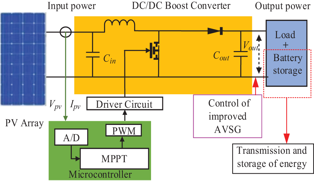
Figure 1: The overall framework of DC microgrid
When the step or random fluctuations occur in the photovoltaic output power and the load output power within the microgrid, the BES can stabilize the certain system power and stabilize the DC bus voltage through the energy storage interface DC/DC converter. However, the introduction of the BES does not fundamentally address the issue of low system inertia in the DC microgrid. Therefore, this paper adopts the AVSG control to tackle the problem of insufficient system inertia. Besides, introducing an adaptive and enhanced control strategy for the AVSG control aims to provide flexible and improved inertial support, enhancing the stability and robustness of the DC bus voltage in response to the power changes within the DC microgrid.
3 Adaptive Control Strategy for DC Microgrid Based on AVSG
In the AC microgrid, the VSG control is usually applied to the DC/AC converter to improve the inertia. The active power-frequency
where
where
Drawing inspiration from the concept of the VSG in the AC microgrid, the AVSG control is implemented in the DC microgrid. Analogous to the
where
The main variable in the AC microgrid is frequency, while in the DC microgrid, the DC bus voltage is the sole indicator to measure the power balance and the stability of the system. Inertia and damping represent the ability to suppress the sudden changes and oscillations in the DC bus voltage. The DC/DC converter lacking inertia features on the DC side is too sensitive to the response of the DC bus voltage, which can cause voltage sudden changes or system instability when responding to external power fluctuations. The introduction of a virtual capacitance with voltage-stabilizing properties slows down voltage changes by utilizing the stored energy. By analogy with the relationship between frequency and power in Eq. (2), the energy stored in
where
Based on the above analysis, the analogous relationships exist between the DC/AC converter with the VSG in the AC microgrid and the DC/DC converter with the AVSG in the DC microgrid. The corresponding analog parameters of the AC microgrid and the DC microgrid are illustrated in Table 1.
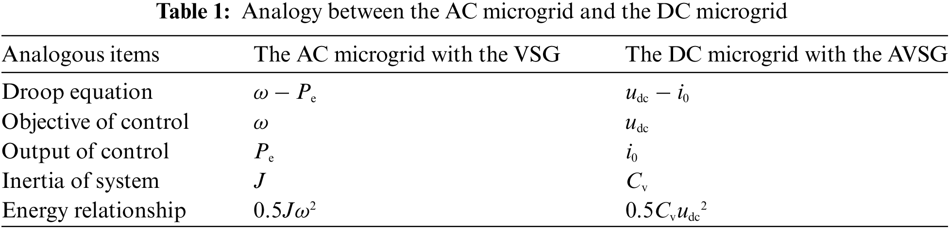
According to the correspondence between the variables between the DC microgrid and the AC microgrid in Table 1, and the analogy of Eqs. (2) and (5), and make adjustments to some variables, the AVSG control equation is shown in Eq. (6).
where
Fig. 2 shows the control block diagram of the energy storage system with the AVSG, which is composed of the BESS (Battery Energy Storage System), the current tracking module, and the AVSG control module. The output voltage
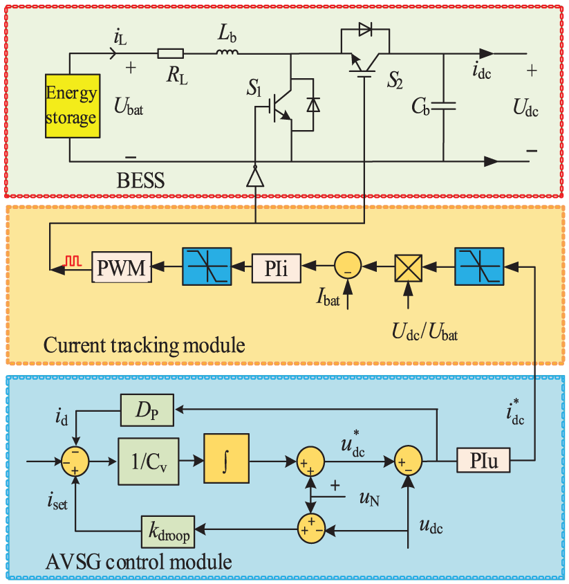
Figure 2: Control block diagram of energy storage system with AVSG
As shown in Fig. 3, the AVSG equivalent model is established on the basis of the droop control equivalent model, and the equivalent components of the AVSG control are introduced. The impedance
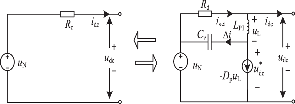
Figure 3: AVSG equivalent model
3.3 AVSG Small Signal Modeling and Inertial Trend Analysis
In order to analyze the specific control effect of the energy storage interface DC/DC converter after the introduction of the AVSG control, suppose the duty cycle of the DC/DC converter is
where
The small-signal linearization of the state average equation is carried out, and the disturbance is introduced near the steady-state operating point, and the instantaneous values of the corresponding DC/DC converter variables are shown in Eq. (9).
where
By sorting out the small signal equation of Eq. (10), the relevant transformation can be deduced. The main transfer function of the DC/DC converter is shown in Eq. (11).
where
Neglecting energy losses, the power balance on both sides of the energy storage interface DC-DC converter is depicted in Eq. (12).
Linearize the small-signal equation of Eq. (12) and neglect the quadratic disturbance, as shown in Eq. (13).
According to the superposition theorem, the small signal disturbance
Laplace transform and small-signal linearization are applied to Eq. (6), yielding the small-signal model controlled by the AVSG as shown in Eq. (15).
The AVSG small-signal model of the established energy storage DC/DC converter is shown in Fig. 4. The voltage outer loop and current inner loop adopt the PI control, as shown in Eq. (16).
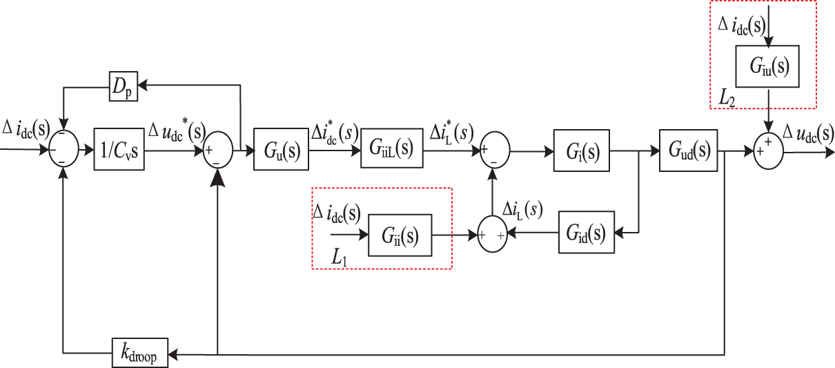
Figure 4: AVSG small signal modeling of energy storage DC/DC converter
where
The AVSG small signal model of the energy storage DC/DC converter is shown in Fig. 4, and the AVSG output current disturbance is shown in Eq. (17).
Combined with the operating characteristics of the PI controller,
According to Eq. (18), the droop coefficient
This article only requires a brief analysis of the relationship between the inertial parameters of the AVSG and the inertia of the DC microgrid, along with the design of the parameter adaptive equation. Fig. 4 reveals that, beyond the main pathway, the AVSG closed-loop system is also influenced by two additional secondary paths
where

Figure 5: Unit step response curve of AVSG control parameter changes
It can be seen from Fig. 5b that a suitable decrease in
3.4 AVSG Adaptive Control and System Stability Analysis
To enable the AVSG control to dynamically adjust
where
when performing parameter adaptive optimization, a high-pass filter (HPF) is used to mitigate the disturbance caused by introducing the differential link to obtain the voltage change rate within the system. This approach facilitates the acquisition of the voltage change rate. Simultaneously, to prevent output voltage oscillations resulting from sudden changes in

Figure 6: The block diagram of AVSG adaptive control
To simplify the analysis, ignoring the influence caused by two secondary paths
By analyzing the closed loop pole distribution trends of
As shown in Fig. 7a, in addition to the fixed poles that have satisfied stability, it is also necessary to analyze the influence of changing poles on the system stability. With the increase of

Figure 7: Closed loop pole distribution diagram of AVSG parameters
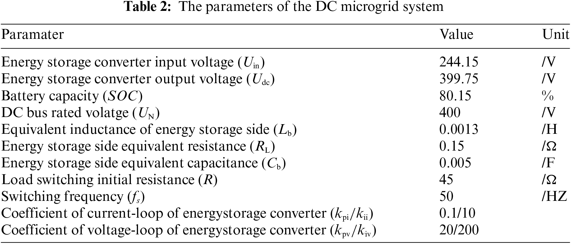
4.1 Simulation Model Construction
To validate the efficacy of the proposed control strategy, a simulation platform is constructed using MATLAB/Simulink, as depicted in Fig. 1. The PV unit operates at a rated temperature of 25°C, with an initial solar irradiance of 600 W/m2. The parameters of the DC microgrid system are provided in Table 2.
4.2 Simulation Waveform under AVSG Control Strategy
4.2.1 The Effect of AVSG Control Parameters on DC Bus Voltage
Scenario 1: in this scenario, the solar irradiance is changed, transitioning from the initial value of 600 to 1000 W/m2 at 1.5 s. Fig. 8 illustrates the simulated waveforms of the DC bus voltage under varying conditions of

Figure 8: Effect of AVSG control parameters on DC bus voltage
In this study, the degree of the fluctuation and dynamic change in the DC bus voltage are used as indicators to reflect the inertia strength of the DC microgrid, as demonstrated in Fig. 9c. When power step disturbances manifest within the microgrid, the inertia of the microgrid is predominantly revealed through the dynamic changes of the DC bus voltage. Moreover, the inertia can also be indirectly reflected by the dynamic response time of the DC bus voltage. The slower the dynamic change of the DC bus voltage, the longer the dynamic response time, and the stronger the inertia of the microgrid. As depicted in Fig. 8a, the dynamic change of the DC bus voltage differs based on different values of

Figure 9: Effect of different control strategies on DC bus voltage
4.2.2 The Effects of Different Control Strategies on DC Bus Voltage
Scenario 2: The initial solar irradiance is 600 W/m², which increases to 1000 W/m² at 1 s and further rises to 1100 W/m² at 2 s. The corresponding changes in photovoltaic output power are depicted in Fig. 9a. In Fig. 9b, the initial load power consumption is 3.5 kW. At 1 s, the load power consumption slightly increases to 3.6 kW. At 2 s, a 35 Ω load is introduced, causing the power to rise to 8 kW. To facilitate clear observation of the control effects, the following initial parameters are chosen for the AVSG:
As depicted in Fig. 9c, it is clear that the AVSG control can effectively mitigate the initial voltage fluctuations of the DC bus under droop control. When photovoltaic and load power shift at 1 and 2 s, the AVSG control augments droop control with fixed
Fig. 10 illustrates that when the rapid changes manifest in the photovoltaic power and load power, corresponding fluctuations arise in the DC bus voltage and its rate of change, and the parameter adjustments of

Figure 10: Parameter changes of AVSG adaptive control
4.2.3 The Effects of Different Control Strategies on the Main Variables of Battery
Analyzing the effects of different control strategies on the key parameters of the battery in Scenario 2.
Observing Figs. 11a and 11b, it becomes evident that changes in microgrid power demand lead to battery overshooting under traditional droop control, which is harmful to the battery’s lifespan. In contrast, both the AVSG control and the AVSG adaptive control eliminate this overshoot phenomenon. The AVSG adaptive control makes the transient change of battery power more apparent, and the battery power responds faster, thereby enhancing the battery’s power support capability. Fig. 11c shows the battery

Figure 11: Changes in key battery parameters under different control strategies
4.2.4 Simulation Waveforms of Different Control Strategies in a Simulated Natural Environment
Scenario 3: Simulating the fluctuation of short-term solar irradiance under natural conditions, with the ambient temperature held at 25°C, the values associated with the AVSG control parameters remain consistent with those in Scenario 2, and the effect of different control strategies on the DC bus voltage is depicted in Fig. 12a.
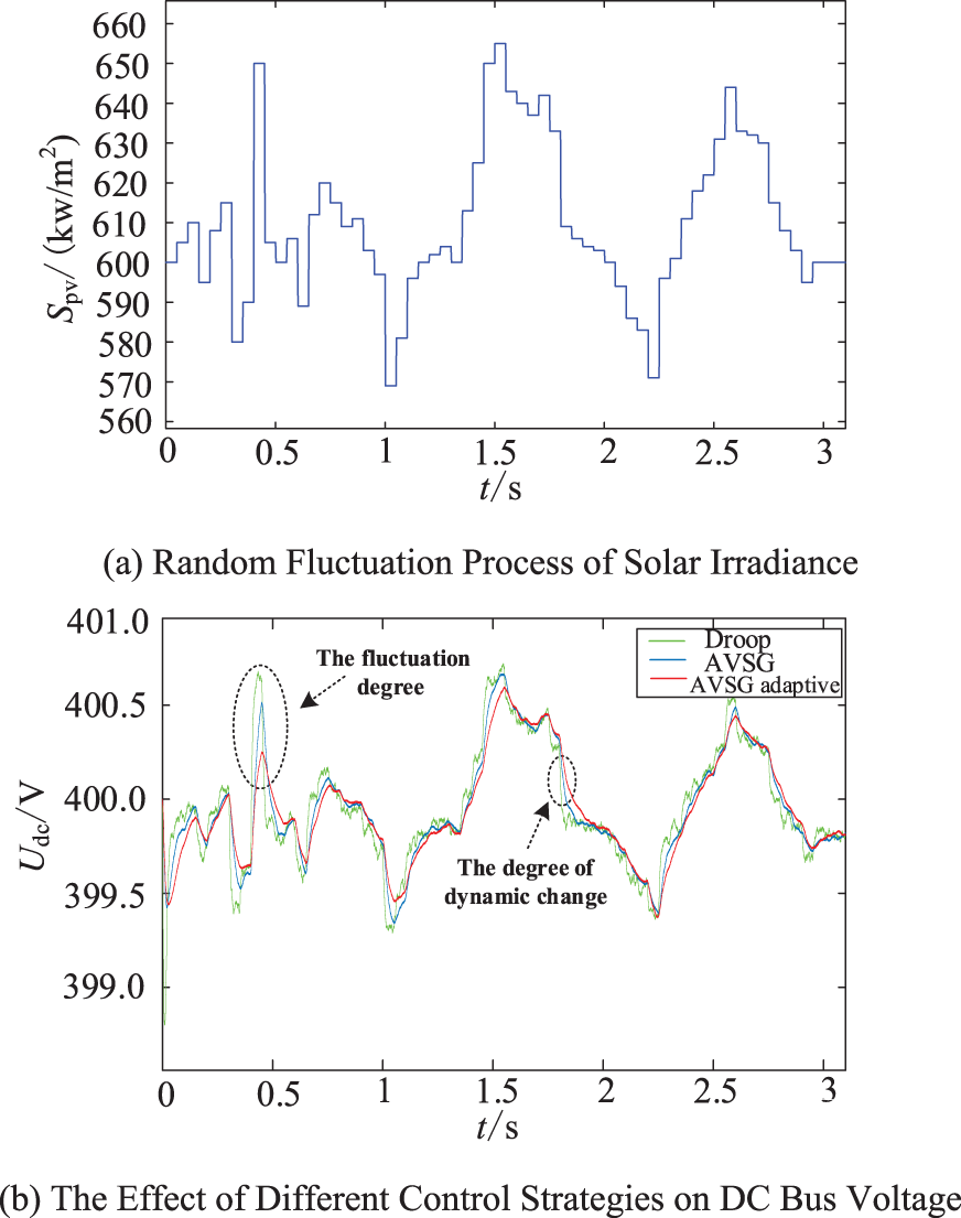
Figure 12: Simulation waveforms in a simulated natural environment
The random load fluctuations exhibit a similar behavior to the photovoltaic fluctuations, so this scenario will not be elaborated upon. In the case of power random fluctuations in the DC microgrid, besides using the dynamic variation of the DC bus voltage as an indicator, the inertia strength of the DC microgrid can be more clearly reflected through the degree of fluctuation in the DC bus voltage. Therefore, the fluctuation of the DC bus voltage is considered the primary indicator. The smaller the voltage fluctuation, the stronger the anti-interference ability of the bus voltage, the larger the inertia of the DC microgrid, the more stable the system. Fig. 12b reveals distinctions in the DC bus voltage waveform under the three control strategies. The degree of fluctuation is attenuated to some extent through the application of the AVSG control. However, there is still room for improvement in the fluctuation suppression effect of the AVSG control on the DC bus voltage. By applying the adaptive control to
In Fig. 13, the significant parameter changes in the AVSG adaptive control occur during periods of random short-term solar irradiance fluctuations, with the voltage change rate tracking coefficients

Figure 13: Parameter changes of AVSG adaptive control
4.3 The Effects of the Values of A and B on the AVSG
The effects of the voltage change rate tracking coefficients
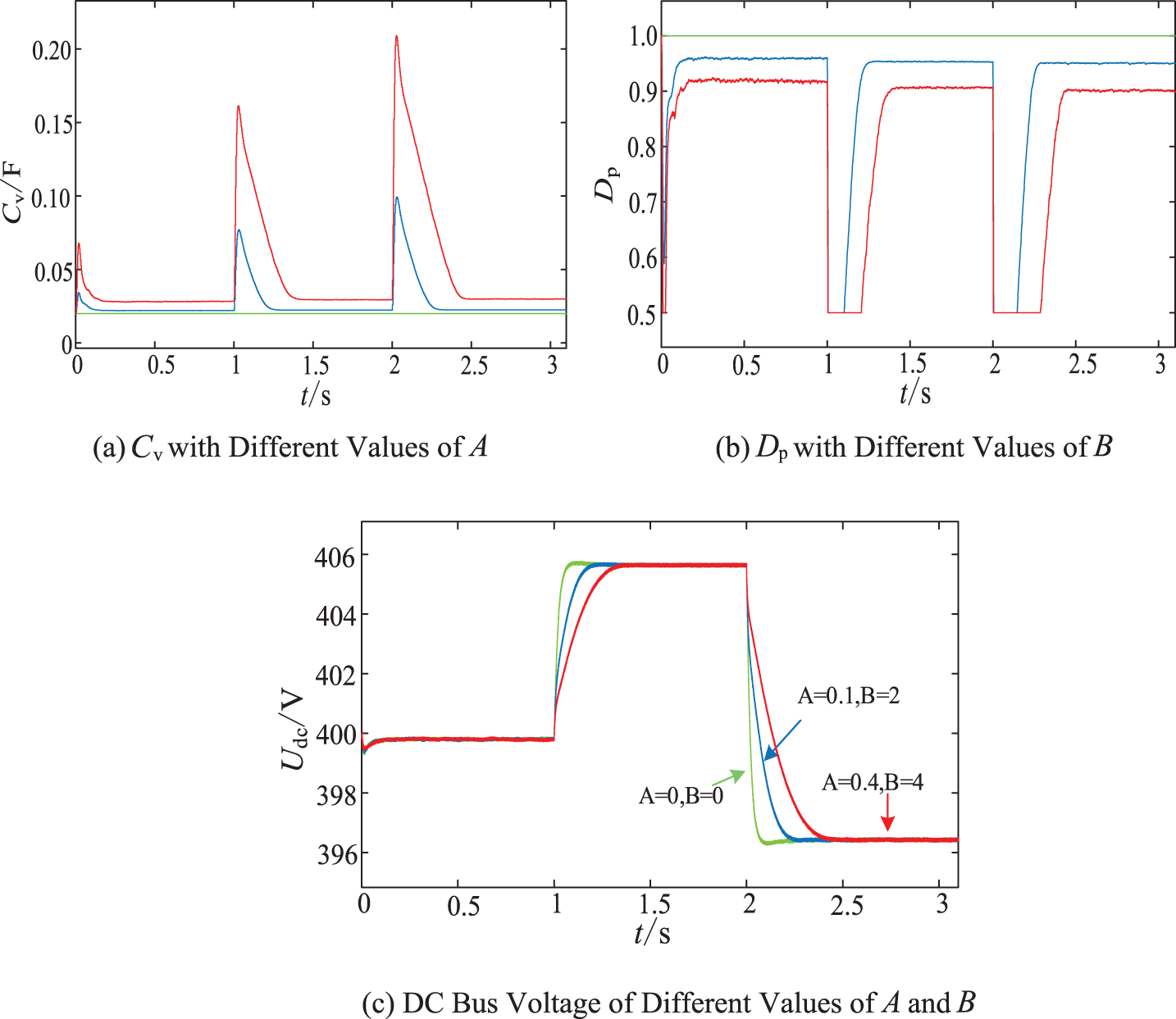
Figure 14: Simulation waveform of the effects produced by
In Fig. 14c, with the increase of
In view of the low inertia and poor anti-interference capability of the DC microgrid equipped with power electronic converters, the AVSG control with virtual capacitance
(1) By incorporating
(2) The implementation of the AVSG adaptive control with voltage change rate tracking coefficients
(3) When power step disturbances occur in the microgrid, the AVSG adaptive control can further slow down the dynamic changes in the DC bus voltage and restrain sudden changes in the DC bus voltage. During random power fluctuations, the fluctuation of the DC bus voltage decreases noticeably. In both scenarios, the stability of the DC bus voltage is optimal under adaptive control, and the DC microgrid connected to the DC bus exhibits the characteristics of “flexible inertia”.
(4) This study exclusively concentrates on the adaptive control of
Acknowledgement: None.
Funding Statement: This work was funded by the National Natural Science Foundation of China (52067013), and the Provincial Natural Science Foundation of Gansu (20JR5RA395).
Author Contributions: The authors confirm their contribution to the paper as follows: Study conception and design: Feng Zhao, Jinshuo Zhang, Xiaoqiang Chen and Ying Wang. Data collection: Feng Zhao, Jinshuo Zhang, Xiaoqiang Chen and Ying Wang. Analysis and interpretation of results: Feng Zhao and Jinshuo Zhang. Draft manuscript preparation: Feng Zhao, Jinshuo Zhang. All authors reviewed the results and approved the final version of the manuscript.
Availability of Data and Materials: Data supporting this study are included within the article.
Conflicts of Interest: The authors declare that they have no conflicts of interest to report regarding the present study.
References
1. Sun, E., Shi, J., Zhang, L., Ji, H., Zhang, Q. et al. (2023). An investigation of battery energy storage aided wind-coal integrated energy system. Energy Engineering, 120(7), 1583–1602. https://doi.org/10.32604/ee.2023.027790 [Google Scholar] [CrossRef]
2. Deng, X., Da, F., Shao, H., Wang, X. (2023). A survey of the researches on grid-connected solar power generation systems and power forecasting methods based on ground-based cloud Atlas. Energy Engineering, 120(2), 385–408. https://doi.org/10.32604/ee.2023.023480 [Google Scholar] [CrossRef]
3. Zhang, W. L., Zhang, H., Zhi, N. (2023). Energy management optimization strategy of DC microgrid based on consistency algorithm considering generation economy. Energy Reports, 9(2), 683–691. https://doi.org/10.1016/j.egyr.2023.03.060 [Google Scholar] [CrossRef]
4. Mansoor, M., Mirza, A. F., Ling, Q., Javed, M. Y. (2020). Novel grass hopper optimization based MPPT of PV systems for complex partial shading conditions. Solar Energy, 198, 499–518. https://doi.org/10.1016/j.solener.2020.01.070 [Google Scholar] [CrossRef]
5. Rahman, M. S., Hossain, M. J., Lu, J., Pota, H. R. (2018). A need-based distributed coordination strategy for EV storages in a commercial hybrid AC/DC microgrid with an improved interlinking converter control topology. IEEE Transactions on Energy Conversion, 33(3), 1372–1383. https://doi.org/10.1109/TEC.2017.2784831 [Google Scholar] [CrossRef]
6. Adib, A., Fateh, F., Mirafzal, B. (2021). Smart inverter stability enhancement in weak grids using adaptive virtual-inductance. IEEE Transactions on Industry Applications, 57(1), 814–823. https://doi.org/10.1109/TIA.2020.3034070 [Google Scholar] [CrossRef]
7. Li, C., Yang, Y., Cao, Y., Aleshina, A., Xu, J. et al. (2023). Grid inertia and damping support enabled by proposed virtual inductance control for grid-forming virtual synchronous generator. IEEE Transactions on Power Electronics, 38(1), 294–303. https://doi.org/10.1109/TPEL.2022.3203049 [Google Scholar] [CrossRef]
8. Ahmed, M., Meegahapola, L., Vahidnia, A., Datta, M. (2022). Adaptive virtual impedance controller for parallel and radial microgrid with varying X/R ratios. IEEE Transactions on Sustainable Energy, 13(2), 830–843. https://doi.org/10.1109/TSTE.2021.3133413 [Google Scholar] [CrossRef]
9. Babayomi, O., Li, Y., Zhang, Z. (2022). Distributed consensus-based reactive power sharing in microgrid: A predictive virtual capacitance control technique. International Journal of Electrical Power and Energy Systems, 141, 108–139. https://doi.org/10.1016/j.ijepes.2022.108139 [Google Scholar] [CrossRef]
10. Samanta, S., Mishra, J. P., Roy, B. K. (2018). Virtual DC machine: An inertia emulation and control technique for a bidirectional DC-DC converter in a DC microgrid. IET Electric Power Applications, 12(6), 874–884. https://doi.org/10.1049/iet-epa.2017.0770 [Google Scholar] [CrossRef]
11. Liu, Z., Liu, Y. (2022). Virtual DC machine control strategy for stability improvement in DC microgrid with constant power loads. 5th IEEE International Electrical and Energy Conference, pp. 2893–2899. Nanjing, China. https://doi.org/10.1109/CIEEC54735.2022.9846249 [Google Scholar] [CrossRef]
12. He, F. Q., Li, Z. Y., Yang, R. F., Wang, G. L. (2020). Active virtual DC generator technique for new-energy unit of offshore platform. Ship Engineering, 42(10), 90–96. https://doi.org/10.13788/j.cnki.cbgc.2020.10.16 [Google Scholar] [CrossRef]
13. Tan, S. C., Dong, G., Zhang, H., Zhi, N., Xiao, X. (2016). Virtual DC machine control strategy of energy storage converter in DC microgrid. 2016 IEEE Electrical Power and Energy Conference, Ottawa, ON, Canada. https://doi.org/10.1109/EPEC.2016.7771749 [Google Scholar] [CrossRef]
14. Zhao, F., Xiao, C. R., Chen, X. Q., Wang, Y. (2023). Research on virtual DC generator-based control strategy of DC microgrid with photovoltaic and energy storage. Energy Engineering, 120(6), 1353–1370. https://doi.org/10.32604/ee.2023.025976 [Google Scholar] [CrossRef]
15. Song, J., Gao, X., Sun, H., Guo, W. (2022). Improved virtual inertia damping adaptive VDG control strategy for DC microgrid hybrid energy storage converter. 4th International Conference on Electrical Engineering and Control Technologies, pp. 1188–1192. Shanghai, China. https://doi.org/10.1109/CEECT55960.2022.10030597 [Google Scholar] [CrossRef]
16. Zhi, N., Ming, X., Ding, Y., Du, L., Zhang, H. (2022). Power-loop-free virtual DC machine control with differential compensation. IEEE Transactions on Industry Applications, 58(1), 413–422. https://doi.org/10.1109/TIA.2021.3119512 [Google Scholar] [CrossRef]
17. Wang, P., Zhao, J., Liu, K. (2021). Parameter-adaptation-based virtual DC motor control method for energy storage converter. IEEE Access, 9, 90795–90804. https://doi.org/10.1109/ACCESS.2021.3091699 [Google Scholar] [CrossRef]
18. Cao, J. B., Wang, L., Huang, H., Wu, J. L., Gao, Y. L. et al. (2021). Virtual inertia control strategy of multi-port converter used in DC micro-grid. Power System Technology, 45(7), 2604–2615. https://doi.org/10.13335/j.1000-3673.pst.2020.0562 [Google Scholar] [CrossRef]
19. Zhu, X. R., Meng, F. Q., Xie, Z. Y. (2019). Control strategy for DC microgrid DC-DC converter based on virtual synchronous generator. Automation of Electric Power Systems, 43(21), 132–140. https://kns.cnki.net/kcms/detail/32.1180.TP.20190611.1745.002.html [Google Scholar]
20. Wu, W. H., Chen, Y. D., Luo, A., Zhou, L. M., Zhou, X. P. (2017). A virtual inertia control strategy for bidirectional grid-connected converters in DC micro-grids. Proceedings of the CSEE, 37(2), 360–370 (In Chinese). https://doi.org/10.13334/j.0258-8013.pcsee.161050 [Google Scholar] [CrossRef]
21. Cao, X. H., Liu, Y. L., Miao, S. H., Li, L., Liu, Z. W. et al. (2020). Research on virtual inertial control strategy of DC/DC converter in DC microgrid considering self-adaptive parameters. High Voltage Engineering, 46(4), 1281–1290. https://doi.org/10.13336/j.1003-6520.hve.20200430020 [Google Scholar] [CrossRef]
22. Zeng, G. H., Liao, H. F., Zhao, J. B., Zhu, X. C. (2022). A self-adaptive control strategy of virtual inertia and a damping coefficient for bidirectional DC-DC converters in a DC microgrid. Power System Protection and Control, 50(6), 65–73 (In Chinese). https://doi.org/10.19783/j.cnki.pspc.210815 [Google Scholar] [CrossRef]
Cite This Article
 Copyright © 2024 The Author(s). Published by Tech Science Press.
This work is licensed under a Creative Commons Attribution 4.0 International License , which permits unrestricted use, distribution, and reproduction in any medium, provided the original work is properly cited.
 Downloads
 Citation Tools