
 Submit a Paper
 Propose a Special lssue
 Open Access
ARTICLE

Hydrogen Permeation Characteristics of Pd-Cu Membrane in Plasma Membrane Reactor
Graduate School of Engineering, Gifu University, Gifu, 501-1193, Japan
* Corresponding Author: Muhd Hadi Iskandar Abd Razak. Email:
Energy Engineering 2024, 121(2), 259-272. https://doi.org/10.32604/ee.2023.043615
Received 07 July 2023; Accepted 25 September 2023; Issue published 25 January 2024
 View Full Text
 Download PDF
Abstract
Hydrogen is an alternative energy source that has the potential to replace fossil fuels. One of the hydrogen applications is as a material for Polymer Electrolyte Membrane Fuel Cells (PEMFC) in fuel cell vehicles. High-purity hydrogen can be obtained using a hydrogen separation membrane to prevent unwanted contaminants from potentially harming the PEMFC components. In this study, we fabricated a plasma membrane reactor and investigated the permeation performance of a hydrogen separation membrane in a plasma membrane reactor utilizing atmospheric pressure plasma. The result showed the hydrogen permeation rate increasing with time as reactor temperature is increased through joule heating. By decreasing the gap length of the reactor from 2 to 1 mm, the hydrogen permeation rate increases by up to 40%. The hydrogen permeation rate increases by 30% when pressure is applied to the plasma membrane reactor by up to 100 kPa.Keywords
Drastic climate change caused by greenhouse gases from the burning of fossil fuels for energy has called for a new alternative energy source [1,2]. With the continuous growth of the world’s population and economy, the energy demand has continued to rise over the years [3]. In addition, the majority of the energy demand is met heavily with the use of hydrocarbons in fossil fuels, which further causes concern on its limited supply as it is depleted upon use [4,5]. This, coupled with the increasing global warming and environmental pollution has made the development of renewable energy sources all the more essential [6,7]. Hydrogen is attracting much attention as a carbon-free and clean energy source as it does not emit greenhouse gases upon usage [8,9]. In terms of raw materials, hydrogen is highly substitutable and it can be produced in a variety of ways. These include gray hydrogen which is hydrogen produced using fossil fuels; blue hydrogen, hydrogen produced from fossil fuels but combined with carbon capture, utilization, and storage technologies to reduce environmental impacts [10]; green hydrogen which is hydrogen produced from renewable energies [11]; and other methods such as hydrogen produced from biomass, nuclear and by-products in various industries [12].
Hydrogen as a renewable energy has the advantage of having a high energy storage capacity, about 120 MJ or 33.33 kWh in just 1 kg of hydrogen, almost double in exceeding most conventional fuels [13,14]. As a result, various researches are being conducted in conjunction with the Hydrogen Grand Challenge ranging from increasing hydrogen production efficiency to minimizing loss during storage and transportation [15].
However, one disadvantage that hydrogen has is its low energy density per weight and volume, resulting in energy loss during transportation and storage [16,17]. To counter this, a hydrogen carrier is often used to store and transport compounds containing hydrogen, and on-site hydrogen generation technology is used to extract the hydrogen for direct utilization [18]. The current main hydrogen carriers include liquefied hydrogen, organic hydrates such as methylcyclohexane, and ammonia [19]. Among these, ammonia is a promising hydrogen carrier candidate due to its easy liquefaction under slight pressurization as well as the high hydrogen content per molecule, about 17.8 wt% or 120 g/L of ammonia [20]. In addition, using ammonia for hydrogen production does not emit greenhouse gases as there is no carbon in the molecule. Ammonia generation and distribution facilities have also already been established including ones that use renewable energy methods for hydrogen generation [21,22]. This is especially beneficial as high-purity hydrogen is being used as material for polymer electrolyte membrane fuel cells (PEMFC) in fuel cell vehicles. However, even though ammonia can be used directly in combustion engines, it cannot be used in low-temperature PEMFC [23]. Due to this, produced hydrogen would need to be separated and purified to remove unwanted contaminants which can potentially harm the PEMFC components [24].
In recent years, palladium-based membranes have attracted significant interest thanks to the advancement in fuel cell technologies [25]. Palladium has a face-centered-cubic (FCC) structure and is the most interesting element for hydrogen separation membranes because of its ability to absorb hydrogen in the interstitial gaps, allowing hydrogen to diffuse rapidly [26,27]. In addition, palladium-based membranes are also seen as viable candidates for use in membrane reactors towards hydrogen production, separation, and purification processes due to their high permeability and perm selectivity. However, pure Pd membranes have been reported to have several weaknesses. At low temperatures below 300°C, the hydrogen separation function may be lost due to hydrogen embrittlement [28,29]. In the above low-temperature region, when hydrogen pressure exceeds the limits, two layers with different hydrogen solubility known as the α-phase (hydrogen solid solution state) and β-phase (hydride state) coexists, causing rapid expansion and contraction of the metal crystal lattice which results in membrane degradation [30]. Pure Pd membranes are also susceptible to membrane poisoning effects, which resulted in the need for Pd membranes to be alloyed with other metallic elements [31]. There have been various researches done on palladium alloy membranes such as combinations of Pd-Ag, Pd-Au, and Pd-Cu [32–34].
In particular, Pd-Cu alloys are shown to stand out as they present low cost while showing more desirable properties including better resistance towards H2S and performing better in terms of hydrogen permeability than pure Pd [35]. Additionally, Pd-Cu alloy membranes also exhibit suppression of hydrogen embrittlement and good resistance to sulfur poisoning [36]. Among the many variables of alloy composition of Pd-Cu, the highest reported values of hydrogen permeability were found to be in the composition of 60 wt% Pd and 40 wt% Cu, operating in the temperature range of 350°C to 450°C [37]. This is thought to be attributed to the high mobility of hydrogen atoms within the body-centered-cubic (BCC) crystal structure compared to the face-centered-cubic (FCC) continuous solid solution structure of the Pd-Cu alloy [38]. In the case of metallic films such as palladium alloys, hydrogen molecules dissociate into hydrogen atoms on the metal surface. The atoms then permeate through diffusion (aqueous dissolution-diffusion mechanism) in the gaps between the lattice surfaces [39]. The atoms then recombine on the other side of the membrane to form hydrogen molecules again. Since only hydrogen that diffuses through the gaps between the crystal lattices can permeate the membrane, it is possible to use this advantageous process to purify ultra-pure hydrogen with a purity of 99.9999% or higher [40].
The purpose of this study is to investigate the hydrogen permeation performance of a Pd-Cu alloy membrane when combined with atmospheric pressure plasma in a plasma membrane reactor. This paper reports the characteristics of hydrogen permeation under different reactor gap lengths, temperature, and pressurized conditions.
Fig. 1 shows the experimental setup for the hydrogen permeation experiment with atmospheric pressure plasma. The experimental setup consists of a gas supply system, a high-voltage pulse power supply, a plasma membrane reactor, a vacuum pump, and a hydrogen gas sensor.
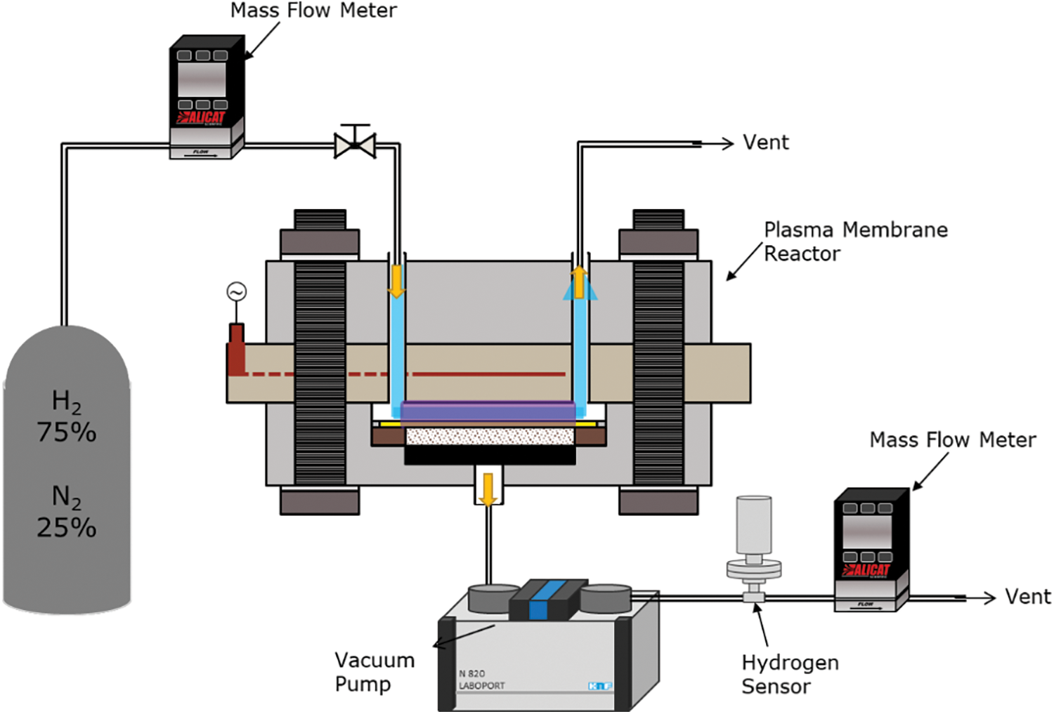
Figure 1: Experimental setup for hydrogen permeation experiment by plasma membrane reactor
A simulated gas of 75% H2 and 25% N2 was used in this study to simulate the complete decomposition of ammonia. The sample gas flow rate was controlled by a mass flow controller (Alicat Scientific, MC Series) and is supplied directly to the inlet port of the plasma reactor. After the decomposition process, a mixture of H radicals, N radicals, and undecomposed gas is vented out at the outlet port. A vacuum pump (Laboport, KNF N840) was used to depressurize the permeation outlet of the reactor to −100 kPa. Since only hydrogen is permitted to pass through the membrane, hydrogen is sucked out from the permeation outlet, and its concentration was measured using a hydrogen gas sensor and the flow rate was measured by a mass flow meter (Alicat Scientific, M Series). A thermocouple was attached to the bottom of the plasma reactor in order to measure the temperature closest to the reaction field.
The plasma membrane reactor (Fig. 2) consists of an upper and bottom flange made up of stainless steel, a ceramic plate with an internal electrode, a flow channel plate, a hydrogen separation membrane, a porous ceramic gas diffusion plate, and some elastic components. There is a gas inlet port and a gas outlet port at the top of the reactor and a permeation outlet port at the bottom of the reactor. The ceramic plate is used as the dielectric layer with a 5 μm thick internal electrode inside the plate. The hydrogen separation membrane was prepared by cutting a large sheet of the membrane into a circular shape to fit into the reactor. Each component is aligned and stacked on top of each other and is sandwiched between the upper and bottom flanges. The entire structure is held together using nuts and bolts surrounding the reactor. The nuts are secured and tightened using a torque wrench in stages up to 20 Nm as not to break the ceramic plate. An assembled reactor is shown in Fig. 3. The flow channel serves as the reaction zone and is a round shape with an outer diameter of 78 mm, with the depth of the flow channel being measured as the gap length of the reactor.
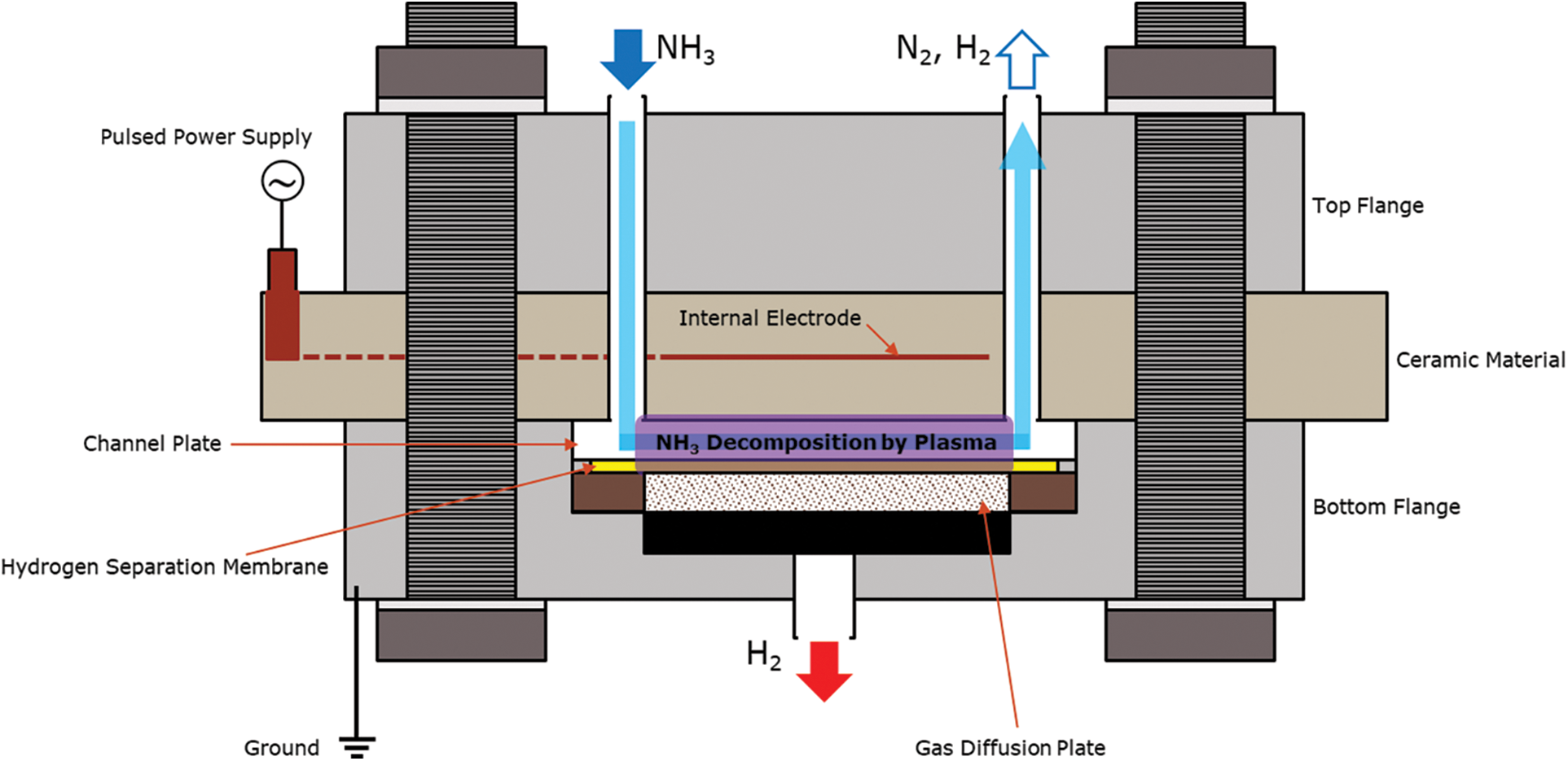
Figure 2: Schematic diagram of plasma membrane reactor
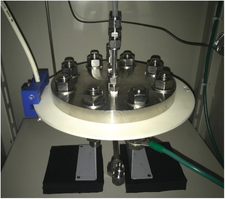
Figure 3: Picture of the assembled plasma membrane reactor
In this work, the reactor gap length used is measured as 1 and 2 mm. Atmospheric pressure plasma is generated within the reactor gap between the internal electrode, which acts as the high-voltage electrode and the main body of the reactor, which acts as the ground electrode. Within the reaction zone, plasma is generated using a high frequency and high voltage power supply (Haiden Laboratory, PHF-2K Type) with a waveform shown in Fig. 4. Atmospheric pressure plasma generated is a dielectric barrier discharge (DBD) plasma. The power supply has an output voltage of 0 to ± 15 kVpp, an output capacitance of 0.5 to 2 kW, and an output frequency of 1 to 100 kHz. A high-voltage probe (Tektronix, P6015A) and an oscilloscope (Tektronix, TDS3034B) were used to measure the waveform. The pulse frequency was kept constant at 10 kHz. The applied voltage (
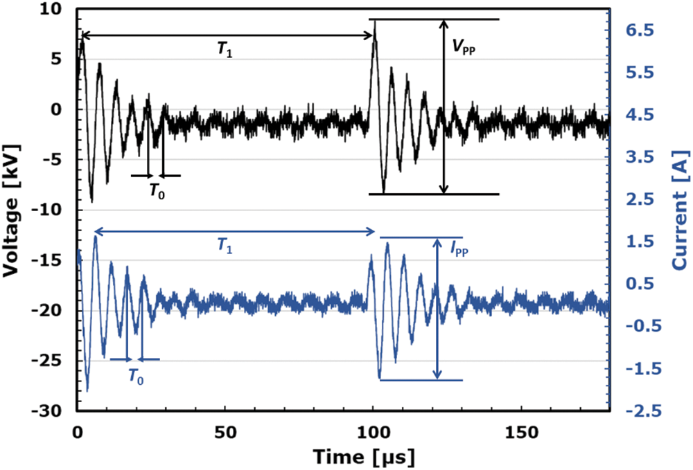
Figure 4: Voltage and current waveform from one sinusoidal power source
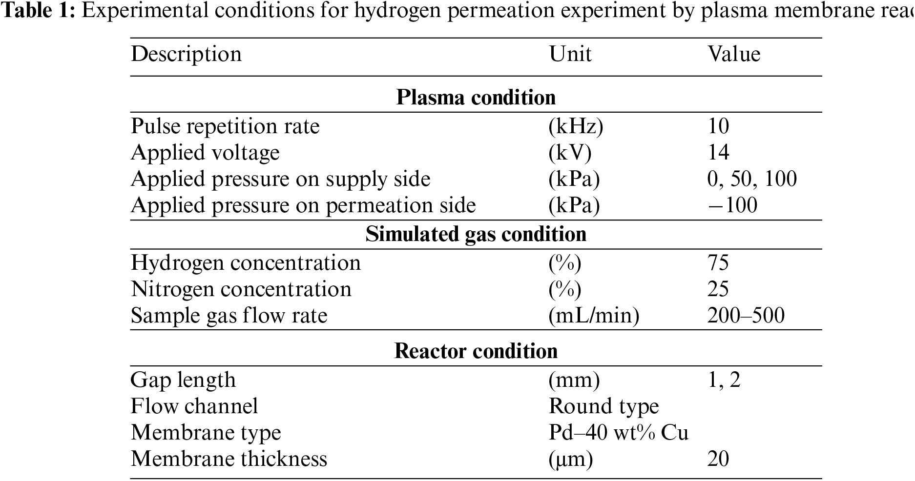
Table 1 lists the experimental conditions for the hydrogen permeation experiment using a plasma membrane reactor. The applied voltage was fixed at 14 kV while the applied pressure on the supplied side was varied from 0–100 kPa. Throughout the experiment, the pressure on the permeation side was set at −100 kPa. The hydrogen separation membrane used in this study is a Pd type membrane with 40 wt% Cu (Tanaka Kikinzoku) in its β-phase.
The plasma decomposition process used in this reactor has the ability to decompose hydrogen to H radicals at low temperatures. Combined with the hydrogen separation membrane, the hydrogen permeation process differs slightly than normal and is shown below (Fig. 5):
1. Hydrogen decomposition by atmospheric pressure plasma
2. Adsorption of H radicals onto the membrane surface
3. Diffusion of H radicals into the membrane
4. Desorption and recombination of H radicals into hydrogen
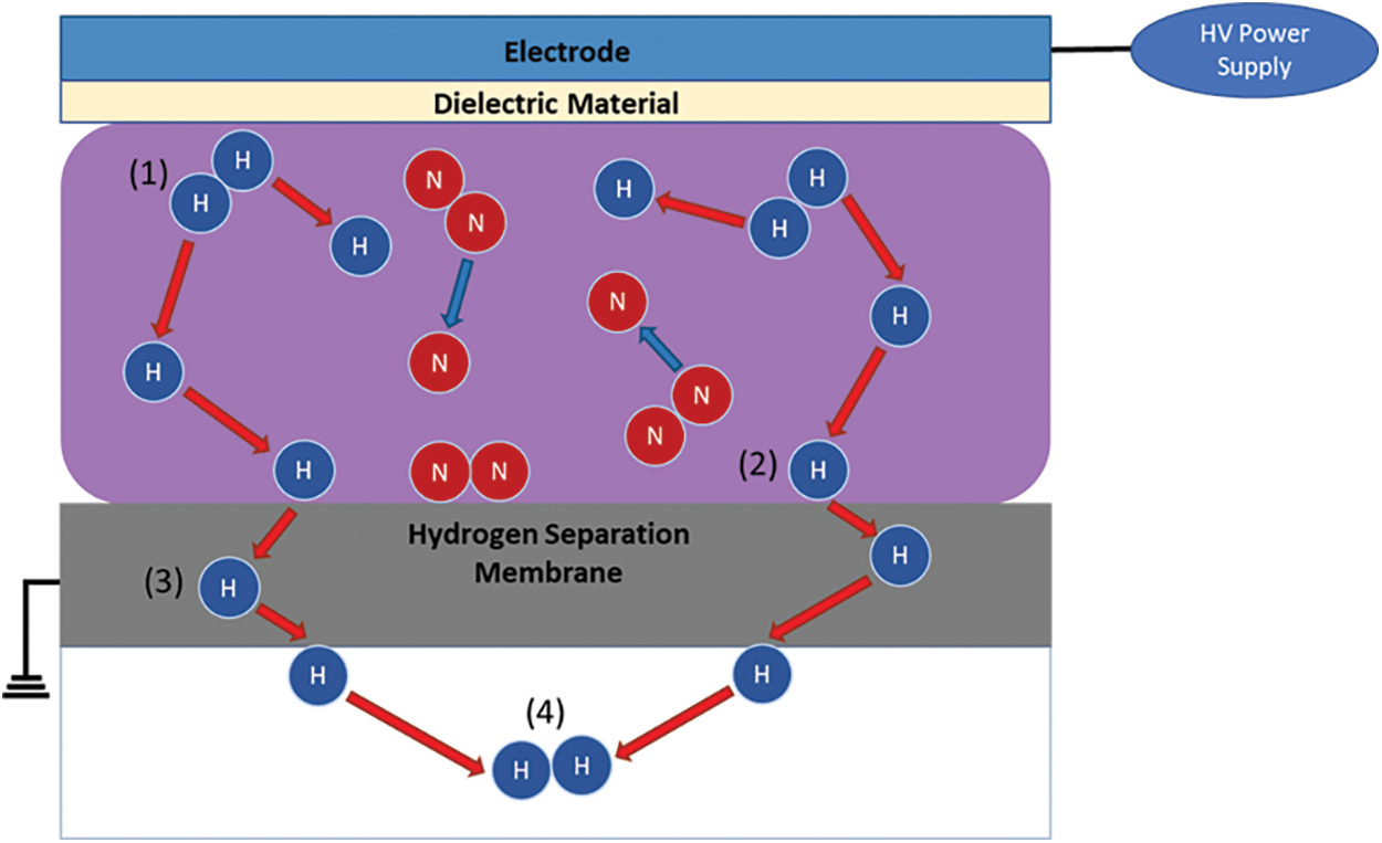
Figure 5: Illustration of hydrogen separation mechanism using atmospheric pressure plasma
3.1 Effect of Reactor Gap Length
First, the hydrogen permeation performance using a plasma membrane reactor was investigated for different sample gas flow rates.
Fig. 6 shows the graph of hydrogen permeation rate and permeated hydrogen flow rate against time for a gap length of 2 mm. The effect of plasma was studied with the applied voltage being kept constant at 14 kV and the sample gas flow rate being varied from 200 to 500 mL/min. The hydrogen permeation rate is defined by the following equation:
where
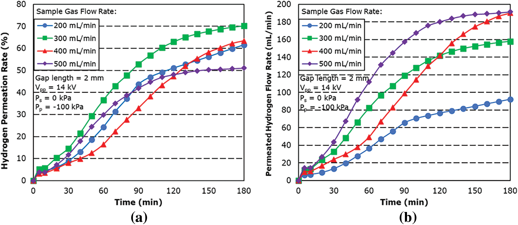
Figure 6: Effect of sample gas flow rate on (a) hydrogen permeation rate and (b) permeated hydrogen flow rate for 2 mm gap length
From the result, the hydrogen permeation rate is shown to increase with time. This is thought to be attributed to the joule heating phenomena which was generated from excess current flow. The temperature recorded from the thermocouple showed a steady increase in the temperature of the reactor across all sample gas flow rates. Since the thermocouple cannot be attached directly to the hydrogen separation membrane as the plasma will cause static interference, the actual temperature of the membrane is not certain. However, it is believed that the temperature inside of the reactor is higher than the one measured by the thermocouple. The results showed an average temperature increase of 0.55°C, 0.42°C, 0.53°C and 0.44°C per minute, with the highest temperature at the 180-min mark being 127°C, 95.7°C, 119.1°C and 96.3°C for supplied flow rates of 200, 300, 400 and 500 mL/min, respectively.
The increase in temperature improves the permeability performance of the hydrogen separation membrane, and the energy required to dissociate hydrogen into H radicals is also decreased due to the active movement of hydrogen molecules in the reaction field.
However, the hydrogen permeation rate is shown to decrease as the sample gas flow rate is increased, particularly from 300 to 500 mL/min. This is thought to be due to the decrease in residence time associated with the increase in sample gas flow rate, which resulted in a decrease in the number of collisions of electrons with hydrogen molecule in the reaction field. Shorter residence time also affects the adsorption rate of H radicals on the membrane surface as shorter contact time with the hydrogen separation membrane does not allow the radicals to be diffused in time.
The maximum hydrogen permeation rate was found to be 70.18% with a sample gas flow rate of 300 mL/min with a maximum hydrogen permeated flow rate of 157.9 mL/min.
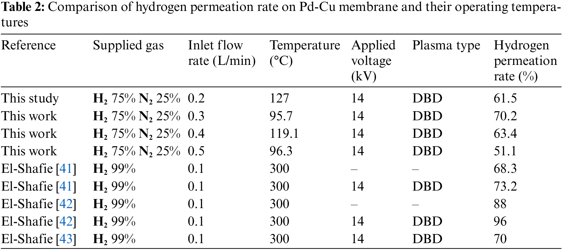
Table 2 summarizes the comparison of hydrogen permeation rate from other studies, showing that although some of the permeation rate from the previous result is lower when compared, it is worth noting that the operating temperature is significantly lower.
In order to further investigate the effect of the hydrogen permeation performance of the reactor, the gap length was changed from 2 to 1 mm while the flow rate was kept the same from 200 to 500 mL/min and the applied voltage was kept at 14 kV.
Fig. 7 shows the hydrogen permeation rate and flow rate for different sample gas flow rate for a 1 mm gap length. The results showed the hydrogen permeability at each sample gas flow rate increasing with time with the maximum hydrogen permeability decreasing with increasing the sample gas flow rates.
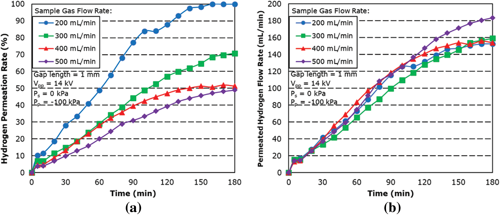
Figure 7: Effect of sample gas flow rate on (a) hydrogen permeation rate and (b) permeated hydrogen flow rate for 1 mm gap length
From the result, 99.9% permeation rate was achieved for 200 mL/min. At sample gas flow rates of 300 to 500 mL/min, it was found that the hydrogen permeation rate does not differ that much from 2 mm gap length result. This is attributed to the stronger plasma effect of the shorter gap length and shorter residence time, which resulted in no large difference in hydrogen permeation rate. However, as a result of a smaller reaction zone and lower residence time, it can be seen that there is a limit towards the amount permeable by the 1 mm gap length, as can be seen in Fig. 7b.
The result also showed a slow increase in the permeation rate for 200 mL/min between the 100-min mark and the 110-min mark before steadily increasing again. This is thought to be attributed to the limit of permeation performance for the hydrogen separation membrane for the temperature at the time. As the temperature continues to increase, the permeation rate then started to increase after the 110-min mark.
The maximum permeation rate was found to be 99.9% with a sample gas flow rate of 200 mL/min with a maximum hydrogen permeated flow rate of 152.7 mL/min, followed by 70.77% for sample gas flow rate of 300 mL/min.
Fig. 8 shows the comparison of hydrogen permeation performance between 1 and 2 mm gap length. Under the same experimental condition, the hydrogen permeation rate for 1 mm is shown to be 40% higher than that of a 2 mm gap length. Even though under a smaller reaction volume, the 1 mm gap length is shown to have better permeation performance due to the decreased spark voltage which allows plasma discharge to occur more easily. The dissociation into H radicals is also further promoted due to the improved lighting condition of the plasma.
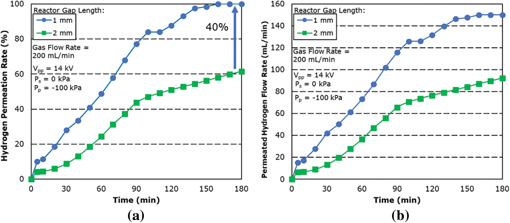
Figure 8: Effect of (a) hydrogen permeation rate and (b) permeated hydrogen flow rate for reactor of different gap length
Fig. 9 shows the graph of the hydrogen permeation rate against the residence time of the reactor. The residence time is calculated based on the amount of gas flowing into the reactor per unit of time and the total volume of the reaction zone and is summarized in the following equation:
where VR is the volume of the reaction field of the reactor and F0 is the sample gas flow rate.
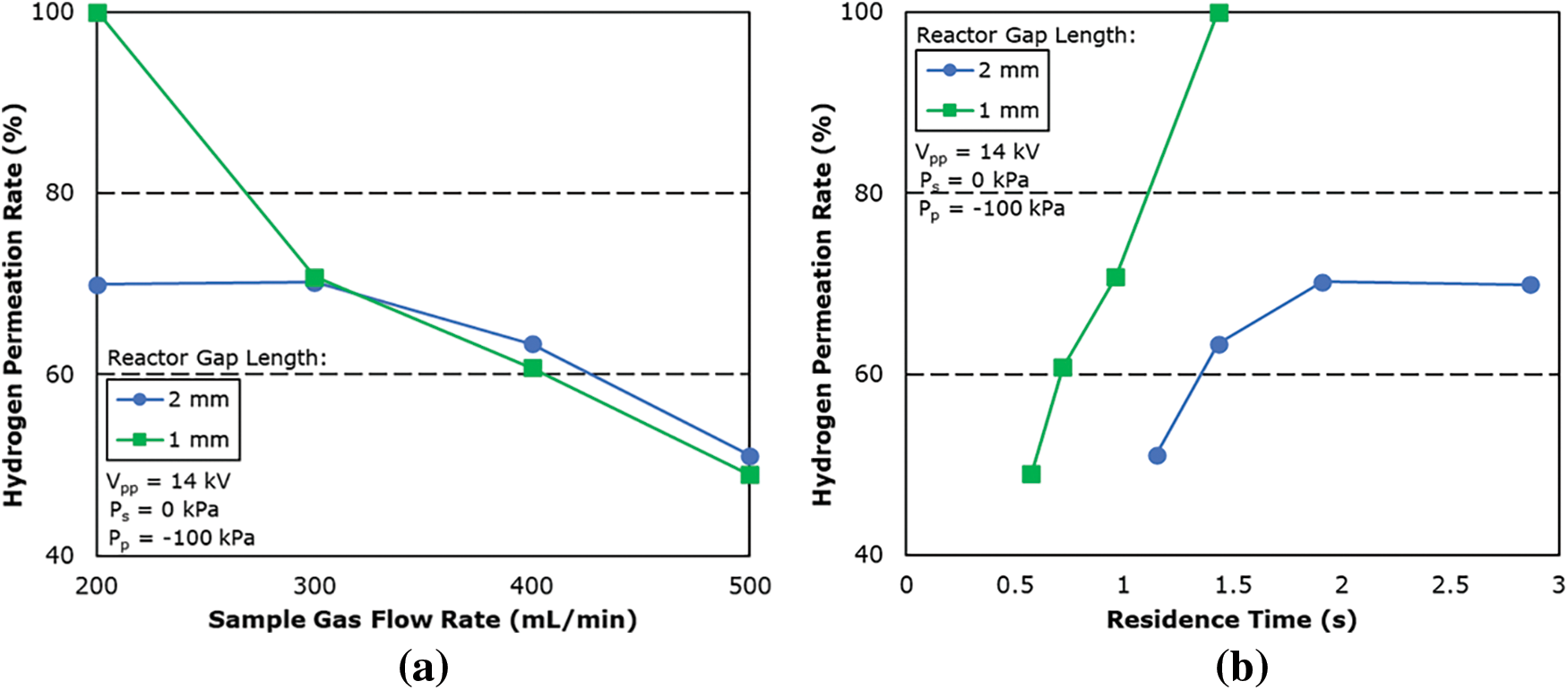
Figure 9: Effect of (a) sample gas flow rate and (b) residence time on hydrogen permeation rate for reactor of different gap length
The reaction field volume of the plasma membrane reactor was calculated as 4.78 and 9.56 mL for 1 and 2 mm gap length, respectively.
From the result, the hydrogen permeation rate is shown to be higher for 1 mm gap length when compared under the same residence time, this confirms that the plasma lighting condition is better for 1 mm gap length even at different sample gas flow rates.
In order to improve the hydrogen permeation rate, the plasma reactor was pressurized by increasing the pressure in the plasma membrane reactor from atmospheric pressure to 50 kPa. The original goal was to investigate the effects of pressurization conditions on both gap lengths. However, plasma firing was not possible for the 2 mm gap length as the electric field becomes smaller with increasing gap length. This causes electrons not being accelerated enough to dissociate the hydrogen molecules. As in the case with a 1 mm gap length, plasma firing was confirmed after the reactor was pressurized.
Fig. 10 shows the hydrogen permeation rate for different sample gas flow rates for applied pressure at 50 kPa and a gap length of 1 mm. The result showed an increase in the hydrogen permeation rate and flow rate when compared to 0 kPa. Under the same experimental condition, hydrogen permeation rate was found to increase by almost 30% across all gas flow rates. This is attributed to the increase in differential pressure from the high-pressure region of the supplying side towards the low-pressure region on the permeation side of the membrane.
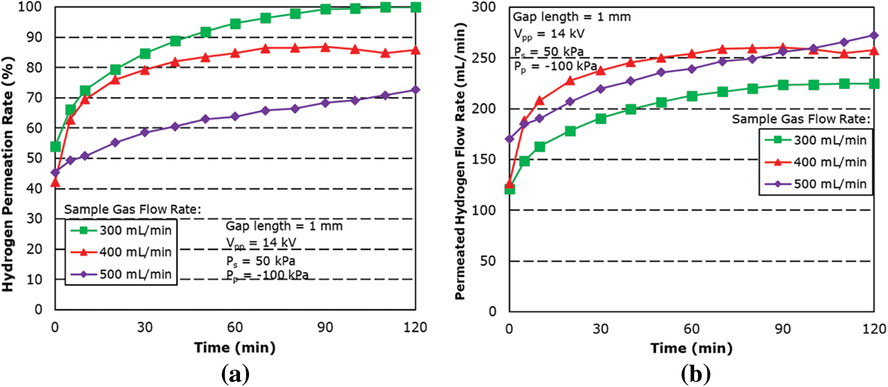
Figure 10: Effect of sample gas flow rate on (a) hydrogen permeation rate and (b) permeated hydrogen flow rate for 50 kPa applied pressure condition
The maximum hydrogen permeation rate was found to be 99.9% for the sample gas flow rate at 300 mL/min and with a permeated hydrogen flow rate at 225 mL/min, followed by 85.90% for the sample gas flow rate at 400 mL/min.
The next step of the experiment is to further increase the applied pressure to 100 kPa. Fig. 11 shows the graph of the hydrogen permeation rate against the applied pressure for different sample gas flow rates. As expected, the results showed that a further increase in applied pressure has also increased the hydrogen permeation rate. However, higher pressurization beyond 100 kPa was found to inhibit plasma firing, even for the 1 mm gap length, as increased pressure causes the density of gas molecules to also increase in the reaction field. This in turn also results in electrons not being accelerated enough to dissociate the gas molecules before and after every collision. From the result, at 100 kPa, the maximum hydrogen permeation rate was 99.9% for a sample gas flow rate of 300 mL/min and a hydrogen permeated flow rate of 225 mL/min, followed by 92.71% for sample gas flow rate of 400 mL/min.
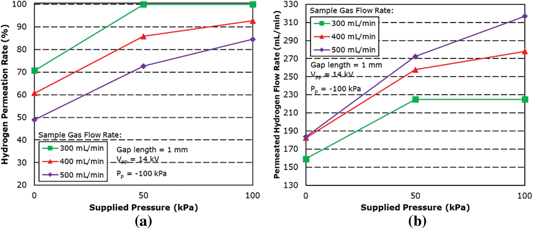
Figure 11: Effect of sample gas flow rate on (a) hydrogen permeation rate and (b) permeated hydrogen flow rate for different applied pressure condition
This research investigates the hydrogen permeation characteristics of a hydrogen separation membrane when used in conjunction with a plasma membrane reactor and atmospheric pressure plasma. This study investigated the hydrogen permeation rate and permeated hydrogen flow rate by varying the sample gas flow rate, reactor gap length, and the applied pressure to the reactor. The results of this study show enhanced hydrogen permeation performance by using atmospheric pressure plasma to dissociate hydrogen molecules before being permeated across the hydrogen separation membrane.
Firstly, we conducted the hydrogen permeation performance of a hydrogen separation membrane utilizing atmospheric pressure plasma. The hydrogen permeation rate increases with time as the reactor temperature is increased by joule heating generated by excess flowing current. The hydrogen permeation rate also decreases with an increase in sample gas flow rate as the residence time is shortened and the frequency of collisions of electrons with molecular hydrogen within the reaction field decreases. In addition, shorter residence time also shortens the contact time of hydrogen radicals with the hydrogen separation membrane, not allowing the hydrogen radicals to permeate in time. The maximum hydrogen permeated rate was 70.18% for a sample gas flow rate of 300 mL/min with a permeated hydrogen flow rate of 157.9 mL/min.
Secondly, the reactor gap length was shortened to 1 mm to investigate its effects on the hydrogen permeation rate. At a shorter gap length, the hydrogen permeation rate improves even though shortening the gap length resulted in a shorter residence time. This increase in permeation rate is due to the reduced spark voltage reducing the distance between the electrodes, which resulted in improved lighting conditions of the generated atmospheric pressure plasma. The maximum permeation rate was 99.9% with a sample gas flow rate of 200 mL/min with a maximum hydrogen permeated flow rate of 152.7 mL/min, followed by 70.77% for a sample gas flow rate of 300 mL/min.
Thirdly, the plasma membrane reactor was pressurized by increasing the pressure on the supply side of the reactor. The hydrogen permeation rate increased after increasing the pressure inside the reactor to 50 and 100 kPa. This is due to the increase in differential pressure between the sides of the hydrogen separation membrane. Higher applied pressure inhibits plasma firing as the density of gas molecules increases. The hydrogen permeation rate was increased by over 25% and 30% when pressure was applied from atmospheric pressure to 50 and 100 kPa, respectively.
Acknowledgement: The authors would like to thank Sato Hiroki for assisting during the preliminary stage of this study.
Funding Statement: The authors received no specific funding for this study.
Author Contributions: The authors confirm contributions to this paper as follows: Study conception and design: Shinji Kambara, Yukio Hayakawa. Data collection: Muhd Hadi Iskandar Abd Razak, Tsuda Motoki. Analysis and interpretation of results: Muhd Hadi Iskandar Abd Razak, Tsuda Motoki, Yukio Hayakawa. Draft manuscript preparation: Muhd Hadi Iskandar Abd Razak. All authors reviewed the results and approved the final version of the manuscript.
Availability of Data and Materials: Readers may contact the corresponding author regarding data used in the study.
Conflicts of Interest: The authors declare that they have no conflicts of interest to report regarding the present study.
References
1. Mikhaylov, A., Moiseev, N., Aleshin, K., Burkhardt, T. (2020). Global climate change and greenhouse effect. Entrepreneurship and Sustainability Issues, 7(4), 2897. [Google Scholar]
2. Wuebbles, D. J., Jain, A. K. (2001). Concerns about climate change and the role of fossil fuel use. Fuel Processing Technology, 71(1–3), 99–119. [Google Scholar]
3. van Ruijven, B. J., de Cian, E., Sue Wing, I. (2019). Amplification of future energy demand growth due to climate change. Nature Communications, 10(1), 2762. [Google Scholar] [PubMed]
4. Dawood, F., Anda, M., Shafiullah, G. M. (2020). Hydrogen production for energy: An overview. International Journal of Hydrogen Energy, 45(7), 3847–3869. [Google Scholar]
5. Bhagea, R., Bhoyroo, V., Puchooa, D. (2019). Microalgae: The next best alternative to fossil fuels after biomass. A review. Microbiology Research, 10(1), 7936. [Google Scholar]
6. Tarhan, C., Çil, M. A. (2021). A study on hydrogen, the clean energy of the future: Hydrogen storage methods. Journal of Energy Storage, 40, 102676. [Google Scholar]
7. Kumar, S. S., Himabindu, V. (2019). Hydrogen production by PEM water electrolysis–A review. Materials Science for Energy Technologies, 2(3), 442–454. [Google Scholar]
8. Lee, D. H. (2012). Toward the clean production of hydrogen: Competition among renewable energy sources and nuclear power. International Journal of Hydrogen Energy, 37(20), 15726–15735. [Google Scholar]
9. Jafari, M., Armaghan, D., Mahmoudi, S. S., Chitsaz, A. (2019). Thermoeconomic analysis of a standalone solar hydrogen system with hybrid energy storage. International Journal of Hydrogen Energy, 44(36), 19614–19627. [Google Scholar]
10. Yu, M., Wang, K., Vredenburg, H. (2021). Insights into low-carbon hydrogen production methods: Green, blue and aqua hydrogen. International Journal of Hydrogen Energy, 46(41), 21261–21273. [Google Scholar]
11. Oliveira, A. M., Beswick, R. R., Yan, Y. (2021). A green hydrogen economy for a renewable energy society. Current Opinion in Chemical Engineering, 33, 100701. [Google Scholar]
12. Javaid, R. (2021). Catalytic hydrogen production, storage and application. Catalysts, 11(7), 836. [Google Scholar]
13. Abe, J. O., Popoola, A. P. I., Ajenifuja, E., Popoola, O. M. (2019). Hydrogen energy, economy and storage: Review and recommendation. International Journal of Hydrogen Energy, 44(29), 15072–15086. [Google Scholar]
14. Balali, Y., Stegen, S. (2021). Review of energy storage systems for vehicles based on technology, environmental impacts, and costs. Renewable and Sustainable Energy Reviews, 135, 110185. [Google Scholar]
15. Borgschulte, A. (2016). The hydrogen grand challenge. Frontiers in Energy Research, 4, 11. [Google Scholar]
16. Elishav, O., Lewin, D. R., Shter, G. E., Grader, G. S. (2017). The nitrogen economy: Economic feasibility analysis of nitrogen-based fuels as energy carriers. Applied Energy, 185, 183–188. [Google Scholar]
17. Sun, S., Jiang, Q., Zhao, D., Cao, T., Sha, H. et al. (2022). Ammonia as hydrogen carrier: Advances in ammonia decomposition catalysts for promising hydrogen production. Renewable and Sustainable Energy Reviews, 169, 112918. [Google Scholar]
18. Rivard, E., Trudeau, M., Zaghib, K. (2019). Hydrogen storage for mobility: A review. Materials, 12(12), 1973. [Google Scholar] [PubMed]
19. Chatterjee, S., Parsapur, R. K., Huang, K. W. (2021). Limitations of ammonia as a hydrogen energy carrier for the transportation sector. ACS Energy Letters, 6(12), 4390–4394. [Google Scholar]
20. Akiyama, M., Aihara, K., Sawaguchi, T., Matsukata, M., Iwamoto, M. (2018). Ammonia decomposition to clean hydrogen using non-thermal atmospheric-pressure plasma. International Journal of Hydrogen Energy, 43(31), 14493–14497. [Google Scholar]
21. di Carlo, A., Dell’Era, A., Del Prete, Z. (2011). 3D simulation of hydrogen production by ammonia decomposition in a catalytic membrane reactor. International Journal of Hydrogen Energy, 36(18), 11815–11824. [Google Scholar]
22. Kojima, Y. (2015). Hydrogen storage and transportation using ammonia. Hydrogen Energy Systems Society of Japan, 36(11), 583–588. [Google Scholar]
23. Halseid, R., Vie, P. J., Tunold, R. (2006). Effect of ammonia on the performance of polymer electrolyte membrane fuel cells. Journal of Power Sources, 154(2), 343–350. [Google Scholar]
24. Lamb, K. E., Dolan, M. D., Kennedy, D. F. (2019). Ammonia for hydrogen storage; A review of catalytic ammonia decomposition and hydrogen separation and purification. International Journal of Hydrogen Energy, 44(7), 3580–3593. [Google Scholar]
25. Zhang, X., Wang, W., Liu, J., Sheng, S., Xiong, G. et al. (2008). Hydrogen transport through thin palladium-copper alloy composite membranes at low temperatures. Thin Solid Films, 516(8), 1849–1856. [Google Scholar]
26. Morozov, M. M., Potekaev, A. I., Klopotov, A. A., Markova, T. N., Klopotov, V. D. (2014). Phase stability in binary palladium alloys. Steel in Translation, 44(12), 890. [Google Scholar]
27. Nenoff, T. M., Spontak, R. J., Aberg, C. M. (2006). Membranes for hydrogen purification: An important step toward a hydrogen-based economy. MRS Bulletin, 31(10), 735–744. [Google Scholar]
28. Endo, N., Furukawa, Y., Goshome, K., Yaegashi, S., Mashiko, K. I. et al. (2019). Characterization of mechanical strength and hydrogen permeability of a PdCu alloy film prepared by one-step electroplating for hydrogen separation and membrane reactors. International Journal of Hydrogen Energy, 44(16), 8290–8297. [Google Scholar]
29. Kim, K. H., Park, H. C., Lee, J., Cho, E., Lee, S. M. (2013). Vanadium alloy membranes for high hydrogen permeability and suppressed hydrogen embrittlement. Scripta Materialia, 68(11), 905–908. [Google Scholar]
30. Howard, B. H., Killmeyer, R. P., Rothenberger, K. S., Cugini, A. V., Morreale, B. D. et al. (2004). Hydrogen permeance of palladium-copper alloy membranes over a wide range of temperatures and pressures. Journal of Membrane Science, 241(2), 207–218. [Google Scholar]
31. Conde, J. J., Maroño, M., Sánchez-Hervás, J. M. (2017). Pd-based membranes for hydrogen separation: Review of alloying elements and their influence on membrane properties. Separation & Purification Reviews, 46(2), 152–177. [Google Scholar]
32. Jokar, S. M., Farokhnia, A., Tavakolian, M., Pejman, M., Parvasi, P. et al. (2023). The recent areas of applicability of palladium based membrane technologies for hydrogen production from methane and natural gas: A review. International Journal of Hydrogen Energy, 48(16), 6451–6476. [Google Scholar]
33. Nayebossadri, S., Speight, J. D., Book, D. (2019). Hydrogen separation from blended natural gas and hydrogen by Pd-based membranes. International Journal of Hydrogen Energy, 44(55), 29092–29099. [Google Scholar]
34. Habib, M. A., Harale, A., Paglieri, S., Alrashed, F. S., Al-Sayoud, A. et al. (2021). Palladium-alloy membrane reactors for fuel reforming and hydrogen production: A review. Energy & Fuels, 35(7), 5558–5593. [Google Scholar]
35. Liguori, S., Kian, K., Buggy, N., Anzelmo, B. H., Wilcox, J. (2020). Opportunities and challenges of low-carbon hydrogen via metallic membranes. Progress in Energy and Combustion Science, 80, 100851. [Google Scholar]
36. Roa, F., Way, J. D., McCormick, R. L., Paglieri, S. N. (2003). Preparation and characterization of Pd-Cu composite membranes for hydrogen separation. Chemical Engineering Journal, 93(1), 11–22. [Google Scholar]
37. Tsuneki, T., Shirasaki, Y., Yasuda, I. (2006). Hydrogen permeability of palladium-copper alloy membranes. Journal of the Japan Institute of Metals, 70(8), 658–661. [Google Scholar]
38. Ma, Y. H., Mardilovich, I. P., Engwall, E. E. (2003). Thin composite palladium and palladium/alloy membranes for hydrogen separation. Annals of the New York Academy of Sciences, 984(1), 346–360. [Google Scholar] [PubMed]
39. Gallucci, F., Fernandez, E., Corengia, P., van Sint Annaland, M., (2013). Recent advances on membranes and membrane reactors for hydrogen production. Chemical Engineering Science, 92, 40–66. [Google Scholar]
40. Hayakawa, Y., Miura, T., Shizuya, K., Wakazono, S., Tokunaga, K. et al. (2019). Hydrogen production system combined with a catalytic reactor and a plasma membrane reactor from ammonia. International Journal of Hydrogen Energy, 44(20), 9987–9993. [Google Scholar]
41. El-Shafie, M., Kambara, S., Hayakawa, Y. (2020). Experimental analysis of plasma and heating effect on H2 permeation behavior through Pd-Cu40% membranes in 1mm gap length plate reactor. International Journal of Hydrogen Energy, 45(49), 26310–26320. [Google Scholar]
42. El-Shafie, M., Kambara, S., Hayakawa, Y. (2020). Study of the plasma and heating effect on hydrogen permeation through Pd0. 60-Cu0. 40 membrane in a micro-channel plate reactor. International Journal of Hydrogen Energy, 45(49), 26300–26309. [Google Scholar]
43. El-Shafie, M., Kambra, S., Hayakawa, Y. (2021). Performance evaluation of hydrogen permeation through pd/cu membrane at different plasma system conditions. South African Journal of Chemical Engineering, 35, 118–125. [Google Scholar]
Cite This Article
 Copyright © 2024 The Author(s). Published by Tech Science Press.
This work is licensed under a Creative Commons Attribution 4.0 International License , which permits unrestricted use, distribution, and reproduction in any medium, provided the original work is properly cited.
 Downloads
 Citation Tools