
 Submit a Paper
 Propose a Special lssue
 Open Access
ARTICLE

Resilience-Oriented Load Restoration Method and Repair Strategies for Regional Integrated Electricity-Natural Gas System
1 Baicheng Power Supply Company, State Grid Jilin Electric Power Co., Ltd., Baicheng, 137000, China
2 School of Electrical Engineering, Northeast Electric Power University, Jilin, 132012, China
* Corresponding Author: Zedong Yang. Email:
Energy Engineering 2024, 121(4), 1091-1108. https://doi.org/10.32604/ee.2023.044016
Received 18 July 2023; Accepted 22 November 2023; Issue published 26 March 2024
 View Full Text
 Download PDF
Abstract
The rising frequency of extreme disaster events seriously threatens the safe and secure operation of the regional integrated electricity-natural gas system (RIENGS). With the growing level of coupling between electric and natural gas systems, it is critical to enhance the load restoration capability of both systems. This paper proposes a coordinated optimization strategy for resilience-enhanced RIENGS load restoration and repair scheduling and transforms it into a mixed integer second-order cone programming (MISOCP) model. The proposed model considers the distribution network reconfiguration and the coordinated repair strategy between the two systems, minimizing the total system load loss cost and repair time. In addition, a bi-directional gas flow model is used to describe the natural gas system, which can provide the RIENGS with more flexibility for load restoration during natural gas system failure. Finally, the effectiveness of the proposed approach is verified by conducting case studies on the test systems RIENGS E13-G7 and RIENGS E123-G20.Keywords
Sets and Vectors
| a/b | Indices of damaged components and depots |
| i/ij | Index of nodes/branches in the distribution network |
| c | Index for crews |
| k | Index of distribution pole |
| θ | Index for the cluster |
| t | Index for time |
| K | Sets of poles in a branch in the distribution network |
| N | Sets of buses |
| G | Sets of nodes |
| L | Sets of branches |
| B | Natural gas pipelines |
| DG | Set of DG |
| GW | Gas wells |
| Dθ | Set of damaged components and depots |
| m/mn | Index of nodes and passive pipelines in the gas system |
| Variables | |
| Sa,θ | Binary variable for damaged component clustering |
| PDG,i,t | Active power output from DG |
| QDG,i,t | Reactive power output from DG |
| Psd,i,t | Active load shedding |
| Qsd,i,t | Reactive load shedding |
| Pki,t, Qki,t | Active/reactive power flow of branch ki |
| Pij,t, Qij,t | Active/reactive power flow of branch ij |
| Squared voltage magnitude at bus i | |
| Squared current magnitude of line ij | |
| Kij,t | Binary variable indicating the status of branch ij |
| yi,t | Binary variable indicating the status of node i |
| pgi,t | Binary variable indicating the status of DG at node i |
| FGW,m,t | Natural gas output from the gas well |
| Fsd,m,t | Natural gas load shedding |
| Fmn,t | Flow of gas from node m to node n |
| pim,t | Nodal gas pressure of node m |
| pe | Failure rate of the lines in the power system |
| pg | Failure rate of the pipelines in the natural gas system |
| Pfk | Failure probability of the pole k |
| Rateg | Earthquake damage rate of the pipelines in natural gas system |
| Cd | Influence coefficient of pipe diameter |
| Cg | Influence coefficient of site soil |
| IMM | Seismic intensity |
| Lg | Length of natural gas pipeline |
| λmn,t | Binary variables representing the gas flow direction |
| βij,t/βji,t | Auxiliary binary variables |
| Binary variable indicating whether crew c visited damaged component a | |
| Binary variable indicating whether crew c moves from components a to b | |
| ATa,c | Arrival time of crew c at damaged component a |
| Binary variable indicating the time step at which the component is repaired | |
| φa | Nodal potential for subtler elimination constraint |
| qa,t | Binary variable for the repair status of the component |
| Parameters | |
| Electricity /gas load shedding cost | |
| α | Fixed cost factor |
| Δt | Repair time step interval |
| Rki/Xki | Power line impedance |
| PD,i,t/QD,i,t | Active and reactive power loads at node i |
| Maximum/minimum squared voltage magnitude | |
| Maximum/minimum squared current magnitude | |
| Maximum/minimum active power output of DG | |
| Maximum/minimum reactive power output of DG | |
| FGW,m,max | The upper limit for gas well output |
| FGW,m,min | The lower limit for gas well output |
| pim,max/pim,min | Maximum/minimum pressure of node m |
| Cmn | Weymouth equation coefficient |
| Bi | Coefficients for DG gas consumption |
| Cz | Coefficient for compressor power consumption |
| ra,c | Crew c’s repair time of component a |
| tra,b,c | Crew c’s travel time between components a and b |
With the accelerating depletion of traditional fossil energy reserves, facilitating the development of renewable energy sources and improving energy utilization have become common global aims [1]. Due to its environmentally friendly features and abundant reserves, natural gas has received worldwide attention. As a result, the installed capacity of gas-fired power generation has been on the rise in recent years. As energy conversion components between the grid and the natural gas network, gas turbines have been subject to large-scale grid integration that has led to a tighter coupling between the grid and the natural gas network [2]. Energy efficiency can be greatly improved when natural gas energy is merged mainly with the electric power system, which is the regional integrated electricity-natural gas system (RIENGS) [3]. However, the occurrence of extreme disasters is more and more frequent, which threatens the safe and reliable operation of the remote sensing system. The coupled nature of integrated energy systems allows the transmission of faults among subsystems. Any interruption of energy supply in these subsystems may impact the operational status of their associated counterparts. When responding to disasters, load restoration strategies can effectively reduce system load loss, while repair scheduling strategies can restore damaged components and bring the system back to normal operation. Therefore, it is essential to explore the load restoration and repair strategies of RIENGS under extreme disasters to enhance the overall system resilience [4].
The grid lines, pipelines, and coupling components of RIENGS can fail during extreme disasters. At this point, critical loads in the system can lose power supply due to damage, resulting in significant economic losses and severe social consequences. Traditional methods to prevent such calamities usually focus on reinforcing the components and adding controllable switches to improve resistance to failures and general system resilience. Reference [5] proposed a scheme that can enhance the resilience of the distribution network by reinforcing towers, lines, and other components, as well as vegetation management. The proper regulation of contact switches can also enhance the load restoration capability of the system. Reference [6] investigated the distribution of network load restoration using a network reconfiguration strategy and considered the operating state and operating cost of contact switches. Reference [7] developed a coordinated load restoration model for network reconfiguration and distributed generation (DG) sources. The system load shedding could be effectively reduced in their model, and the resilience of the distribution network was improved. Reference [8] proposed an islanding strategy for multi-fault scenarios, where the system can be formed into an intentional islanding pattern by controlling DG sources to provide power support for critical loads. Reference [9] introduced an optimization model for distribution network load restoration and minimized the load shedding and switching operations of the system. The studies mentioned above are relatively mature in terms of investigating the distribution grid load restoration after disasters, whereas the exploration of integrated energy systems still needs to be enriched.
In recent years, the dependency between electric and natural gas systems has strengthened [10], which makes it necessary to utilize the recovery strategies of integrated energy systems when the subsystems experience extreme disasters. Reference [11] evaluated the reliability of electric and natural gas systems. Reference [12] introduced a heuristic two-stage strategy for system failure repair is proposed. Reference [13] argued that the load recovery of the grid can be improved by agents providing the natural gas system with information about failures in the electric system and enabling the natural gas system to take action (e.g., natural gas system load shedding operation) in conjunction with the electric system after taking into account the recovery benefits. These strategies can allow the system to maximize load recovery after an extreme disaster. However, if the recovery of damaged components after a disaster is not accomplished in a timely manner, the system can experience increased economic losses. Therefore, the issue of dispatching repair crew is critical to reducing outage time and load shedding. To maximize repair efficiency and restore the damaged components to normal operation as soon as possible, the system should optimize the dispatch of repair personnel after a failure. Reference [14] summarized the model of repair personnel dispatch and proposed a subloop elimination constraint. Reference [15] introduced an optimal dispatch strategy for removable emergency resources and provided energy distribution to achieve dynamic load restoration for distribution networks coupled with transportation networks under extreme disasters. References [16,17] investigated the recovery and repair strategy of the distribution system after a disaster and proposed a method for the collaborative optimization of repair crew and distributed energy sources, which could effectively improve the resilience of the distribution system. Reference [18] developed a repair scheduling optimization model for the joint electric-gas system.
Although the above studies have proposed many effective post-disaster repair strategies, they did not fully consider the coordinated and optimal operation of RIENGS. Based on this requirement and existing research, to fully coordinate the local energy sources in the electric and natural gas systems, this paper develops a load restoration and repair scheduling optimization model with the RIENGS as the target system. In this model, the power system repair crew and the natural gas system repair crew coordinate the repair tasks. The distribution network reconfiguration strategy is used throughout the process to ensure that the system is quickly restored to a safe and stable operating state while working according to a radial topology. A detailed mathematical model is developed based on the operational characteristics of RIENGS that need to be studied. After the system suffers an extreme disaster, the RIENGS faulty network reconfiguration model is established first, and subsequently, the RIENGS maintenance scheduling model is established so that the system coordinates the network reconfiguration strategy with the maintenance strategy for recovery. Finally, a solver is used to solve the optimization model to derive the optimization strategy.
In addition, this paper uses a bi-directional gas flow model in natural gas pipeline modeling, which allows for more accurate gas flow direction and gas network load recovery results in cases of gas network failure. The rest of this paper is organized as follows: Section 2 clusters and groups the damaged components. The RIENGS load restoration and repair scheduling optimization model is introduced in Section 3. In Section 4, an arithmetic case analysis is performed for the RIENGS E13-G7 and RIENGS E123-G20 systems to verify the validity and practicality of the proposed model. The conclusion is provided in Section 5.
2 Clustering of Damaged Components
Once the system has experienced an extreme disaster, the repair crew needs to repair the damaged components in the distribution network and the natural gas network. At the same time, the system reconfigures the network while repairing the damaged components to meet the radial topology operation requirements of the distribution network. Reference [14] claimed that the dispatching problem of the repair crew can be regarded as a vehicle path problem, i.e., a certain repair crew starts at a repair station, repairs the damaged components one by one according to the developed repair path, and returns to the repair station to which it belongs after all repair tasks have been completed. To reduce the computational complexity of the repair problem, a clustering method that assigns damaged components to depots is used in this paper. Before the repair crew is dispatched, the damaged components are clustered, and their repair tasks are assigned to each repair station. Subsequently, each repair station will send repair crew to repair the clustered components [19].
The value of the binary variable is 1 if the damaged component is assigned to repair station θ, otherwise it is 0. The damaged component clustering can be modeled as follows:
In Eq. (1), the objective function is to minimize the total distance from the damaged part to the warehouse. Eq. (2) guarantees that each component is aggregated into only one warehouse. A cluster of damaged components is shown in Fig. 1.
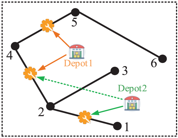
Figure 1: Illustration of the clustering method
3 Load Restoration and Repair Crew Dispatch Model for RIENGS
The purpose of RIENGS recovery and repair after a failure is to quickly repair damaged components after an energy supply interruption, to ensure a stable energy supply and reduce economic losses. Therefore, the objective function is to minimize the overall load reduction cost and the total repair time of damaged components. As a means to introduce the load loss cost factor to emphasize the difference of loads in the RIENGS, the objective function is shown in Eq. (3).
where the first item represents the distribution network load reduction cost, the second item denotes the natural gas grid load reduction cost, the third item represents the loss cost corresponding to the total repair time of all damaged components, and α is a fixed cost factor, so adding the third term to the objective function can make the repair crew fix all damaged components as soon as possible.
3.2 Power System Operational Constraints
In this paper, the DistFlow power flow model is utilized to model the power flow under fault conditions of the distribution network [20], and the binary state variables of lines are added to the Distflow power flow constraint to characterize the fault and normal operation state of lines. The following constraints are obtained:
1) Distribution network operation constraints:
2) Voltage drop equation constraint:
3) Node voltage and branch current constraints:
4) Load curtailment constraint:
5) DG running constraint:
6) The second-order cone form of the branch current constraint is as follows:
3.3 Natural Gas System Operational Constraints
The natural gas network consists of a natural gas source, a gas pipeline, a gas load, and a compressor. The compressor compresses the gas and delivers it through the pipeline to generate the natural gas load. The natural gas network operates with the following constraints:
1) Nodal gas flow balance:
2) Gas well capacity constraint:
3) Natural gas node pressure constraints:
4) Pipeline flow equation:
Under normal operating conditions of the natural gas system, the pipeline gas flow direction is fixed for a short period [19,21]. However, when a natural gas system fails, the direction of the gas flow may change, hence this paper considers the bidirectional flow model of the gas as shown in Eqs. (18)–(23), to ensure that the gas flows from the high-pressure node to the low-pressure node. By introducing the Boolean variable λmn,t, the direction of gas flow in a natural gas system is indicated [22]. When λmn,t = 0,
The second-order cone relaxation for Eq. (23) yields:
The Eqs. (18)–(22) guarantee that natural gas flows from the high-pressure node to the low-pressure node.
The above constraints can ensure that the gas in the natural gas pipeline model can flow from the high-pressure node to the low-pressure node, so that the gas flow direction of the pipeline will be more flexible and the model can adapt the model to the situation of the pipeline flow direction change under fault conditions [22].
3.4 Power-Gas Coupling Constraints
Compressors in the natural gas grid consume electricity, thus they can be thought of as grid loads. Distributed gas turbines in the distribution network consume natural gas, which can be used as a natural gas load.
The coupling components include a distributed gas turbine and an electrically driven compressor with the following energy conversion constraints:
The energy conversion of the electric drive compressor is expressed as follows:
Thus, Eq. (4) translates to:
Then, Eq. (14) translates to:
3.5 Topology Reconfiguration Constraints
The radial structure of the distribution network should be guaranteed during operation, and the reconstruction constraints are as follows:
Eqs. (29)–(32) are radial constraints that convert the network of the distribution network into a directed graph by assigning binary variables (
3.6 Repair Crew Dispatch Constraints
Taking the grouped repair station and the faulty component as the entire set, represented by DN, the repair crew scheduling has the following constraints:
1) Repair crew dispatch constraints:
Eq. (33) indicates the correspondence between
Assuming that the journey of the repair crew is from a to b, the relationship between the time of arrival to b and the repair time and travel time is as follows:
2) Damaged component repair constraints:
Eq. (40) indicates that the component must be repaired within the repair time; Eqs. (41) and (42) show the repair time constraint of the damaged component, where ε is a very small number.
3) Subtour elimination constraints:
Each repair crew group should look for a single repair path: start from the warehouse, repair the damaged components, and return to the warehouse. However, due to the repair model, sub-circuits appear in the repair route, that is, connections between damaged components that are not connected to the warehouse to form a loop [14].
In order to eliminate the above sub-circuits of the repair path, this paper introduces a dummy variable
4) Damaged component state constraints:
Eq. (44) represents the relationship between the state of damaged components and their repair variables; Eq. (45) represents the relationship between the state of distribution network branches and the state of damaged component repair; Eq. (46) represents the relationship between the state of distributed energy and the state of damaged component repair; Eq. (47) represents the relationship between the state of natural gas pipelines and the state of damaged component repair.
The occurrence of earthquake disaster can cause damage to the lines in the power system and the pipelines in the natural gas system. The failure rate models model for RIENGS under earthquake disaster is as follows:
1) Failure rate model for the lines in the power system:
2) Failure rate model for the pipelines in the natural gas system:
The earthquake damage rate of the pipelines in natural gas system is shown in Eq. (49).
The failure rate of the pipelines in the natural gas system under earthquake disaster can be expressed as follows:
The model proposed in this paper is transformed into a MISOCP model. An efficient solution can be achieved by using the existing solver CPLEX. RIENGS Load Recovery and Restoration Scheduling Methodology under Extreme Disaster Conditions The flowchart of the method is shown in Fig. 2. After the system encounters a fault, the optimal recovery strategy of the system is obtained by coordinating the fault recovery strategy and fault repair strategy and solving the optimization model.
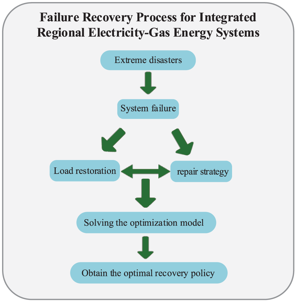
Figure 2: Flowchart of RIENGS load recovery and restoration scheduling methodology
In this paper, two RIENGSs are used as examples for analysis, and the system parameters are shown in reference [23]. We set one hour to represent the repair time step. The time it takes for the service crew to move between damaged components is proportional to their respective distances. The model is solved using the YALMIP toolbox CPLEX12.6 solver in Matlab simulation environment.
4.1 A 13-Node-Power System with a 7-Node Gas System
The improved topology of the system is shown in Fig. 3. Among them, G1 denotes a distributed photovoltaic power source; G2 and G3 represent distributed gas turbines. The compressor is electrically driven and powered by the power system node 4. The power system contains contact switches T1 and T2. There are three repair stations in the entire system, each with a repair group, and the power system repair crew and natural gas system repair crew cannot repair each other. Assuming that the repair time of the distribution line and natural gas pipeline is 1 h, and the repair time of DG and compressor is 2 h. The location coordinates of the repair station are shown in Fig. 3, and the coordinates of other system components are described in reference [23].
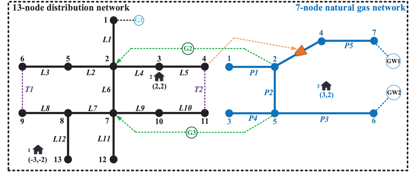
Figure 3: Topology for 13-node power system with 7-node gas system
1) Case 1. Optimization Result: In Case 1, the system suffers damage from an extreme event. In the distribution network, branches L3, L6, L8, L11, L12 and the gas turbines G2, G3 fail. In the natural gas network, pipelines P2, P3, P5 fail. Assuming that the time of failure is 12 h, the load curves are shown in Fig. 4.
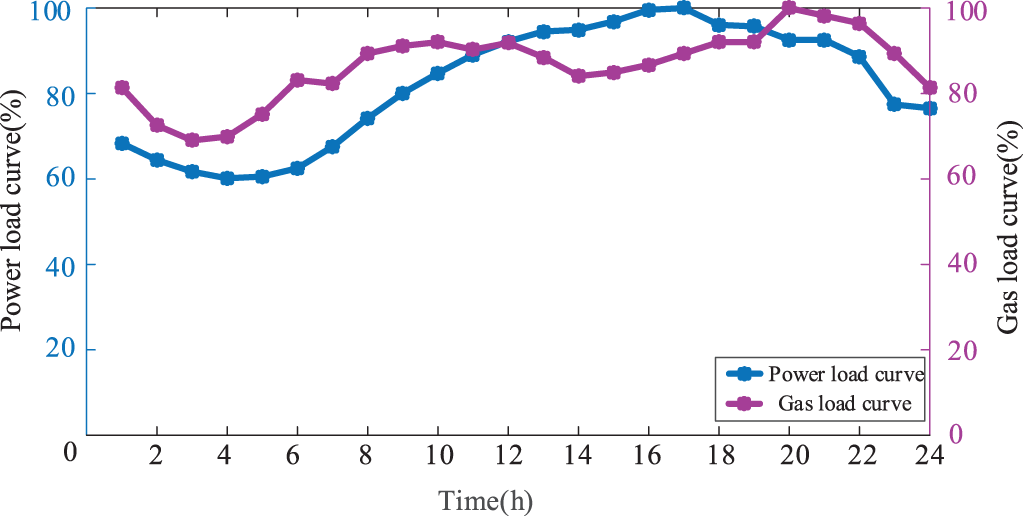
Figure 4: Load curve
According to the damage situation of the system, the dispatch center develops the optimal repair path while adjusting the contact switch action during the recovery process. This is to ensure that the whole system has been operating with the optimal topology, and its repair path is shown in Table 1.

The load shedding of the RIENGS during the repair process is shown in Fig. 5. From t = 1 h to t = 3 h, RIENGS loses most of its load due to the high number of damaged components while the repair crew are on the way to perform repair. In the distribution system, the load loss is minimized by closing the contact switch T2 to ensure the supply of important loads. In the distribution network, at t = 4 h, repair crew No. 2 repair G2 in the distribution network, and the effective output of G2 makes the load reduction in the distribution system begin at this time. At t = 6 h, repair group No. 1 repairs branch L12 and restores power to the critical load at node 13. At t = 8 h, repair group No. 2 repairs gas turbine G3, and the load shedding in the distribution network is further reduced. Meanwhile, in the natural gas system, pipeline P3 is repaired at t = 8 h, at which point the natural gas load is fully restored to normal.
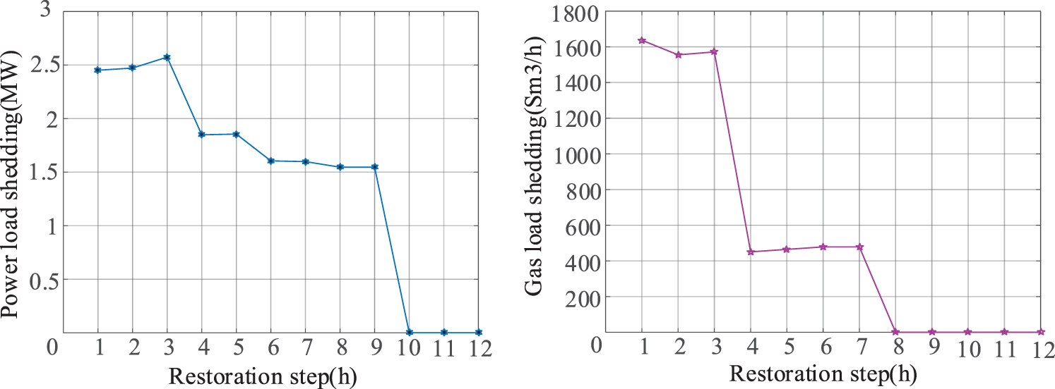
Figure 5: Result of load shedding during repair
The contact switch also plays a key role in the entire load restoration and repair process of the post-disaster system, keeping the system operating in a radially constrained manner and minimizing load shedding along with the repair strategy. At t = 3 h, repair group No. 1 finishes repairing L8 and restores power to the load at node 9, contact switch T1 is closed, allowing the load at node 6 to be restored through the contact switch. In addition, the coordinated repair of the RIENGS in the repair process is reflected in the fact that, at t = 4 h, the gas system restores the gas supply at node 2. At the same time, G2 in the distribution system is repaired and put into operation by repair group No. 2. This coordinated repair strategy can improve the repair efficiency. Finally, as a result of the repair work, at t = 10 h, the operation of branch L11 in the distribution network is fully restored. Although the distribution network branch L6 is still in the disconnection fault, the proper closure of the contact switch makes the whole RIENGS restore all loads, and the load loss is 0.
In summary, when the system suffers a disaster, the optimal repair path and network reconfiguration strategy are coordinated and optimized to allow the system to operate in an optimal topology and reduce load loss. The above results demonstrate the effectiveness of the RIENGS load restoration and repair strategy proposed in this paper in the reduction of load shedding.
2) Case 2. Optimization Result: The time spent by the repair crew on the road between damaged components affects the efficiency of the whole repair task and thus the recovery efficiency of the entire system, and the location of the repair station influences the way the damaged components are clustered. Thus, even under the same cluster grouping, different repair orders affect the whole repair process. Therefore, this study section sets the following scenarios for analysis:
Case 2-1: The failure situation in the system is the same as in Case 1 while changing the locations of the three repair stations in the system but using the same clustering results.
Case 2-2: The failure situation in the system is the same as in Case 1 while changing the locations of the three repair stations in the system, and the clustering results are different from Case 1 and Case 2-1.
The locations of the repair stations in Case 2-1 and Case 2-2 and their clustering results are shown in Figs. 6 and 7.
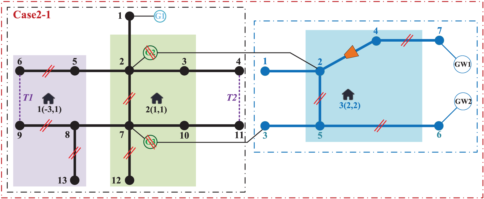
Figure 6: Location diagram of the repair station in Case 2-1
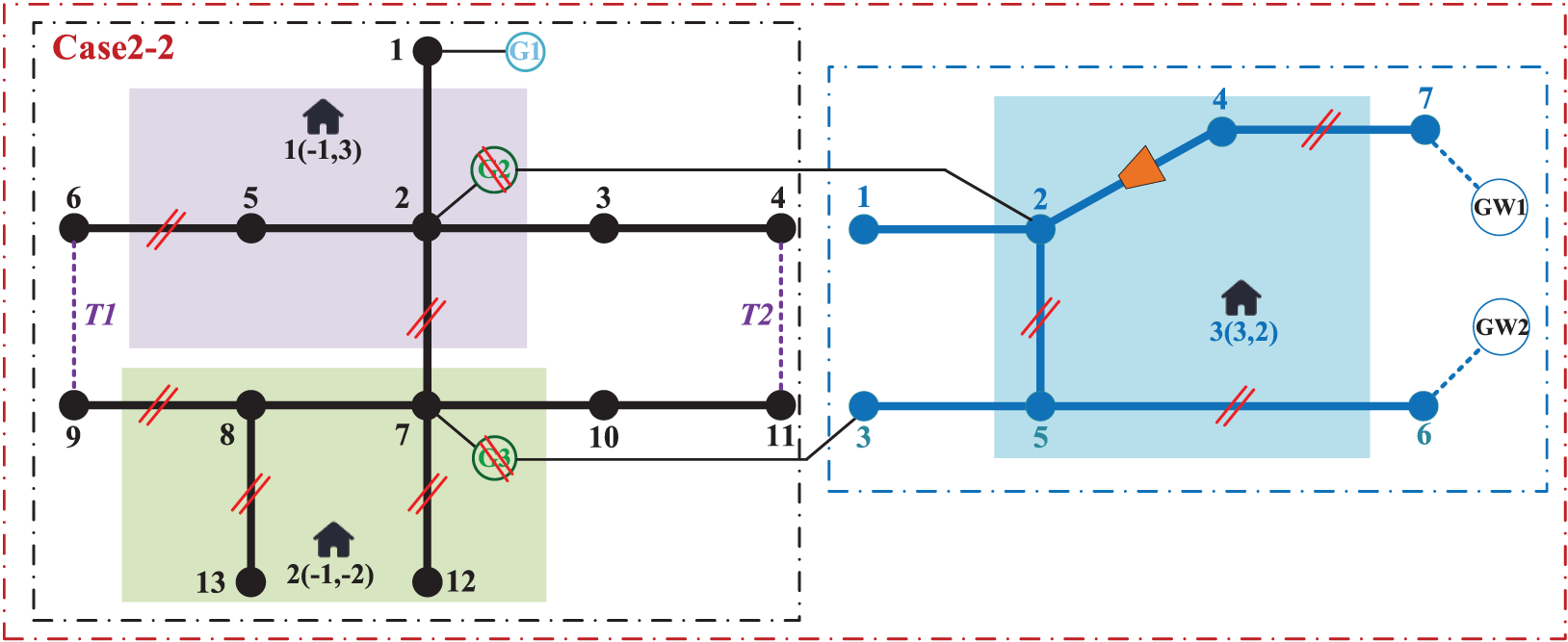
Figure 7: Location diagram of the repair station in Case 2-2
A comparison of the load reduction costs between Case 1, Case 2-1, and Case 2-2 are shown in Table 2. In Case 2-1, the repair station is closer to the damaged component, reducing the time consumed by repair personnel on the repair road, so the load recovery is more efficient and system load reduction costs are lower in Case 2-1 than Case 1.

Comparing Case 2-1 and Case 2-2, it can be found that different warehouse locations lead to different clustering results, which affect the overall repair efficiency. For example, in Case 1, G2 and G3 are grouped in the same repair cluster and are repaired separately by a group of repair crew, while in Case 2-2, G2 and G3 are in different clusters, reducing the recovery time for these turbines. Therefore, the distribution system load reduction cost in Case 2-2 is the lowest. In summary, the repair routes are sensitive to the geographic location of repair stations, and if they are scheduled near critical loads, they may have faster repair capabilities when disaster strikes. In addition, the correct grouping of repair tasks can also complete the entire system more quickly. In conclusion, the appropriate placement of repair stations in regional RIENGS can improve the overall repair efficiency when a disaster strikes.
4.2 123-Node-Power System with a 20-Node Gas System
In order to further validate the effectiveness of the RIENGS load restoration and repair strategy optimization model proposed in this paper, the IEEE-123 node system and 20-node natural gas system developed by the reference [23] are used for validation, and their topologies are shown in Fig. 8.
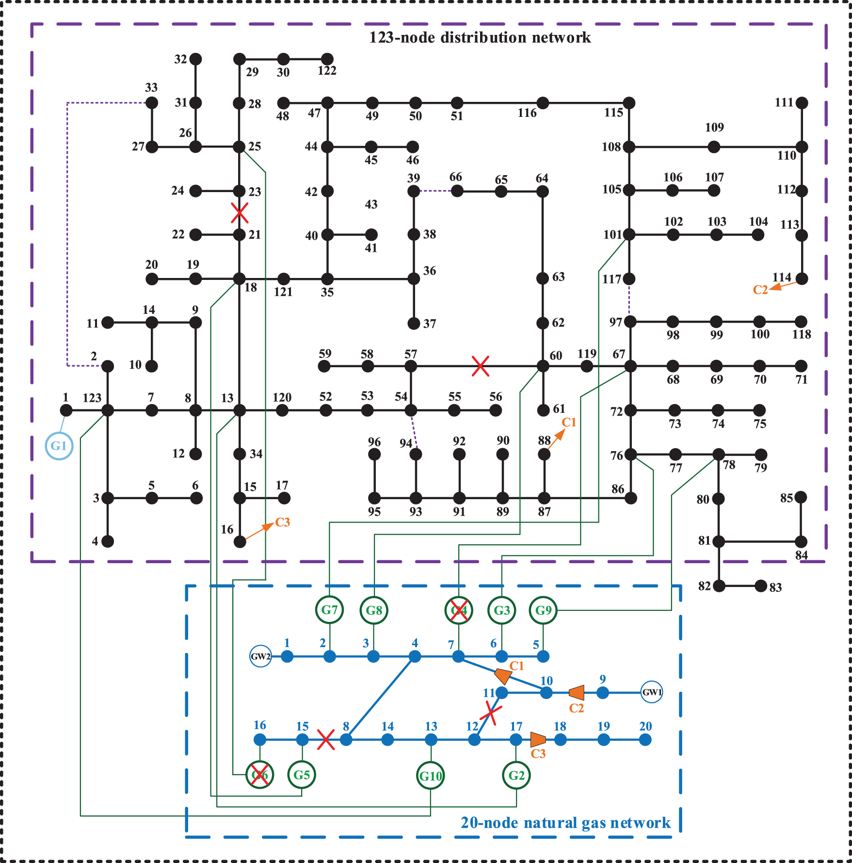
Figure 8: Topology of 123-node power system with 20-node natural gas system
1) Case 3. Optimization Result: In Fig. 8, there are nine gas turbines with one PV DG in the power system, there are four contact switches in the power system, and compressors C1, C2 and C3 exist in the natural gas system, powered by power system nodes 88, 114 and 16, respectively. The repair time of the distribution network branch and gas distribution network pipeline is 1 hour, the repair time of the DG supply and gas turbine is 2 h, and the repair time of the electric drive compressor is 4 h. There are two repair stations in the electric system and one repair station in the gas system.
In order to further analyze the effectiveness of the proposed load restoration and repair scheduling optimization model, this case assumes the following fault scenario:
In the distribution system, faults occur in branches 21–23 (l22), 57–60 (l58), and distributed gas turbines g4 and g6. In the natural gas system, faults occur in pipes 11–12 (p8) and 8–15 (p12), and the faults are shown in Fig. 7. The repair paths for each group of repair crews in Case 3 are shown in Table 3.

Table 3 shows the repair crew’s optimal route in Case 3. From Table 3, it can be seen that repair crew 1 prioritize the repair of the fault on line l22 over the priority repair of the distributed energy. This is because the contact switch reconfigures the system topology after a fault, allowing the faulted area to remain in normal operation through the contact switch. Therefore, the line has a higher repair priority. The load shedding of the RIENGS during the repair process is shown in Fig. 9. In Case 3, the overall load reduction cost is 12465 $, and the total repair time is 32 h.
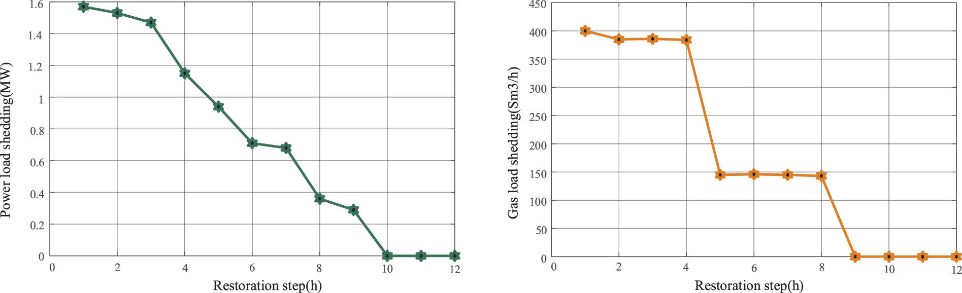
Figure 9: Result of load shedding during repair
Based on the RIENGS load restoration and repair scheduling model proposed in this paper, it is possible to quickly recover as much load as possible using network reconfiguration recovery, and simultaneous decisions are made to prioritize the repair of the more critical failed components. Through the coordinated optimization of the two recovery strategies, the load reduction cost of the entire system can be significantly reduced, thus improving the resilience of the system to cope with extreme scenarios.
For the post-disaster resilience enhancement strategy of the RIENGS under extreme disaster conditions, this paper proposes a coordinated optimization model for load restoration and repair scheduling. The optimal power supply from DG sources to the system is achieved by manipulating the contact switches in the distribution system after a disaster, and the critical loads are restored on a priority basis. At the same time, the damaged components are clustered before the optimal repair schedule is developed, and the network reconstruction method is used to synchronize the system topology during the repair process. The following conclusions are obtained: the proposed optimization model can effectively shorten the customer outage time and improve the system restoration efficiency. On this basis, the effects of the location of the repair station and different clustering repair cases on the repair efficiency are studied, and the data show that the proposed optimization strategy can effectively reduce the system load reduction cost.
Of note, this study was conducted in a centralized model that assumes that a single dispatch center can control the distribution and natural gas systems; however, this ignores the information exchange and management barriers between the electric and natural gas systems. In addition, this paper does not consider the impact of traffic and road conditions on the system restoration process. Future work will focus on system resilience enhancement strategies that take into account conditions such as roadway obstructions.
Acknowledgement: The authors would like to thank the support in part by the Science and Technology Project of State Grid Jilin Electric Power Co., Ltd. (Project Name: Research on Distribution Network Resilience Assessment and Improvement Technology for Natural Disaster Areas).
Funding Statement: This research is funded by the Science and Technology Project of State Grid Jilin Electric Power Co., Ltd. (Project Name: Research on Distribution Network Resilience Assessment and Improvement Technology for Natural Disaster Areas).
Author Contributions: The authors confirm contribution to the paper as follows: study conception and design: Keqiang Wang and Pengyang Zhao; data collection: Keqiang Wang, Changjian Wang, and Zimeng Zhang; analysis and interpretation of results: Yu Zhang, Jia Lu, and Zedong Yang; draft manuscript preparation: Keqiang Wang, Pengyang Zhao, and Zedong Yang. All authors reviewed the results and approved the final version of the manuscript.
Availability of Data and Materials: The authors promise that all data supporting the results of this paper are available.
Conflicts of Interest: The authors declare that they have no conflicts of interest to report regarding the present study.
References
1. van Beuzekom, I., Hodge, B. M., Slootweg, H. (2021). Framework for optimization of long-term, multi-period investment planning of integrated urban energy systems. Applied Energy, 292, 116880. [Google Scholar]
2. Li, S., Guo, L., Zhang, P., Wang, H., Cai, Z. et al. (2018). Modeling and optimization on energy efficiency of urban integrated energy system. 2018 2nd IEEE Conference on Energy Internet and Energy System Integration, pp. 1–6. Beijing, China. [Google Scholar]
3. Zheng, X. Y., Zhan, X. Y., Zhang, W. B., Li, N., Meng, C. et al. (2017). A modelling and optimization toolkit for integrated urban energy system. 2017 IEEE Conference on Energy Internet and Energy System Integration, pp. 1–6. Beijing, China. [Google Scholar]
4. Gazijahani, F. S., Salehi, J., Shafie-Khah, M. (2023). A parallel fast-track service restoration strategy relying on sectionalized interdependent power-gas distribution systems. IEEE Transactions on Industrial Informatics, 19(3), 2273–2283. [Google Scholar]
5. Wei, Y., Wang, J., Feng, Q., Chen, C., Kang, C. et al. (2016). Robust optimization-based resilient distribution network planning against natural disasters. IEEE Transactions on Smart Grid, 7(6), 2817–2826. [Google Scholar]
6. Vargas, R., Macedo, L. H., Home-Ortiz, J. M., Romero, R. (2021). Optimal restoration of distribution systems considering temporary closed-loop operation. IEEE Systems Journal, 15(4), 5483–5494. [Google Scholar]
7. Ding, T., Lin, Y., Li, G., Bie, Z. (2017). A new model for resilient distribution systems by microgrids formation. IEEE Transactions on Power Systems, 32(5), 4145–4147. [Google Scholar]
8. Bie, Z., Lin, Y., Li, G., Li, F. (2017). Battling the extreme: A study on the power system resilience. Proceedings of the IEEE, 105(7), 1253–1266. [Google Scholar]
9. Yong, L., Xiao, J., Chen, C., Tan, Y., Cao, Y. (2019). Service restoration model with mixed-integer second-order cone programming for distribution network with distributed generations. IEEE Transactions on Smart Grid, 10(4), 4138–4150. [Google Scholar]
10. Chen, R., Wang, J., Sun, H. (2018). Clearing and pricing for coordinated gas and electricity day-ahead markets considering wind power uncertainty. IEEE Transactions on Power Systems, 33(3), 2496–2508. [Google Scholar]
11. Li, G., Bie, Z., Kou, Y., Jiang, J., Bettinelli, M. (2016). Reliability evaluation of integrated energy systems based on smart agent communication. Applied Energy, 167, 397–406. [Google Scholar]
12. Asadi, Q., Ashoornezhad, A., Falaghi, H., Ramezani, M. (2023). Optimal repair crew and mobile power source scheduling for load restoration in distribution networks. 2023 International Conference on Protection and Automation of Power Systems (IPAPS), pp. 1–6. Tehran, Iran. [Google Scholar]
13. O’Malley, C., Delikaraoglou, S., Roald, L., Hug, G. (2020). Natural gas system dispatch accounting for electricity side flexibility. Electric Power Systems Research, 178, 106038. [Google Scholar]
14. Bektas, T. (2006). The multiple traveling salesman problems: An overview of formulations and solution procedures. Omega, 34(3), 209–219. [Google Scholar]
15. Wang, Y., Xu, Y., Li, J., Li, C., He, J. et al. (2020). Dynamic load restoration considering the interdependencies between power distribution systems and urban transportation systems. CSEE Journal of Power and Energy Systems, 6(4), 772–781. [Google Scholar]
16. Arif, A., Ma, S., Wang, Z., Wang, J., Ryan, S. M. et al. (2018). Optimizing service restoration in distribution systems with uncertain repair time and demand. IEEE Transaction on Power Systems, 33(6), 6828–6838. [Google Scholar]
17. Lei, S., Chen, C., Li, Y., Hou, Y. (2019). Resilient disaster recovery logistics of distribution systems: Co-optimize service restoration with repair crew and mobile power source dispatch. IEEE Transactions on Smart Grid, 10(6), 6187–6202. [Google Scholar]
18. Lin, Y., Chen, B., Wang, J., Bie, Z. (2019). A combined repair crew dispatch problem for resilient electric and natural gas system considering reconfiguration and DG islanding. IEEE Transaction on Power Systems, 34(4), 2755–2767. [Google Scholar]
19. Chen, S., Conejo, A. J., Sioshansi, R., Wei, Z. (2019). Unit commitment with an enhanced natural gas-flow model. IEEE Transactions on Power Systems, 34(5), 3729–3738. [Google Scholar]
20. Baran, M. E., Wu, F. F. (1989). Optimal sizing of capacitors placed on a radial distribution system. IEEE Transactions on Power Delivery, 4(1), 735–743. [Google Scholar]
21. Wang, C., Wei, W., Wang, J., Bai, L., Liang, Y. et al. (2018). Convex optimization based distributed optimal gas-power flow calculation. IEEE Transactions on Sustainable Energy, 9(3), 1145–1156. [Google Scholar]
22. Li, G., Yan, K., Zhang, R., Jiang, T., Li, X. et al. (2022). Resilience-oriented distributed load restoration method for integrated power distribution and natural gas systems. IEEE Transactions on Sustainable Energy, 13(1), 341–352. [Google Scholar]
23. Wang, S., Sarker, B. R., Mann, L., Triantaphyllou, E. (2004). Resource planing and a depot location model for electric power restoration. European Journal of Operational Research, 155(1), 22–43. [Google Scholar]
Cite This Article
 Copyright © 2024 The Author(s). Published by Tech Science Press.
This work is licensed under a Creative Commons Attribution 4.0 International License , which permits unrestricted use, distribution, and reproduction in any medium, provided the original work is properly cited.
 Downloads
 Citation Tools